

Page 1
Micropaq
®
Monitor
Directions for use
Model 406 and Model 408
Software version 1.7X
Page 2

ii Welch Allyn Micropaq Monitor
© 2010 Welch Allyn. All rights are reserved. No one is permitted to reproduce or duplicate, in any form, this manual or any
part thereof without permission from Welch Allyn.
Welch Allyn assumes no responsibility for injury or for any illegal or improper use of the product that may result from failure
to use this product in accordance with the instructions, cautions, warnings, or indications for use published in this manual.
Welch Allyn, Acuity, Micropaq, and FlexNet
Nellcor
is a registered trademark of Nellcor Puritan Bennett.
are registered trademarks of Welch Allyn.
Masimo and SET are registered trademarks of Masimo Corporation.
Software in this product is copyright by Welch Allyn or its vendors. All rights are reserved. The software is protected by
United States of America copyright laws and international treaty provisions applicable worldwide. Under such laws, the
licensee is entitled to use the copy of the software incorporated within this instrument as intended in the operation of the
product in which it is embedded. The software may not be copied, decompiled, reverse-engineered, disassembled or
otherwise reduced to human-perceivable form. This is not a sale of the software or any copy of the software; all right, title
and ownership of the software remain with Welch Allyn or its vendors.
For information about any Welch Allyn product, please call Welch Allyn Technical Support:
USA + 1 315 685 4560
Canada 800 561 8797 China + 86 216 327 9631
European Call
Center
Germany + 49 7477 92 71 86 Japan + 81 3 3219 0071
Latin America + 1 305 669 9003 Netherlands + 31 15 750 5000
Singapore + 65 6419 8100 South Africa + 27 11 777 7555
United Kingdom + 44 20 7365 6780 Sweden + 46 8 58 53 65 51
800 535 6663
+ 35 3 46 906 7790 France + 33 1 60 09 33 66
Australia + 61 2 9638 3000
800 074 793
REF 103512 (CD)
Manual Part Number 80015977 Ver A, 2010-04
Welch Allyn Protocol, Inc.
8500 SW Creekside Place
Beaverton, OR 97008-7107 USA
Welch Allyn Ltd
Navan Business Park
Dublin Road, Navan
County Meath, Republic of Ireland
www.welchallyn.com
Page 3

Contents
1 - General information . . . . . . . . . . . . . . . . . . . . . . . . . . . . . . . . . . . . . . 1
iii
Intended use. . . . . . . . . . . . . . . . . . . . . . . . . . . . . . . . . . . . . . . . . . . . . . . . . . . . . 1
General warnings and cautions. . . . . . . . . . . . . . . . . . . . . . . . . . . . . . . . . . . . . . . 4
Introducing the monitor . . . . . . . . . . . . . . . . . . . . . . . . . . . . . . . . . . . . . . . . . . . . 7
Understanding the monitor and the FlexNet Network . . . . . . . . . . . . . . . . . . . . . 8
Monitor features . . . . . . . . . . . . . . . . . . . . . . . . . . . . . . . . . . . . . . . . . . . . . . . . . . 9
Accessories . . . . . . . . . . . . . . . . . . . . . . . . . . . . . . . . . . . . . . . . . . . . . . . . . . . . 16
Operating settings . . . . . . . . . . . . . . . . . . . . . . . . . . . . . . . . . . . . . . . . . . . . . . . 16
Demonstration mode . . . . . . . . . . . . . . . . . . . . . . . . . . . . . . . . . . . . . . . . . . . . . 17
2 - Monitoring . . . . . . . . . . . . . . . . . . . . . . . . . . . . . . . . . . . . . . . . . . . . . 19
Connect a new patient . . . . . . . . . . . . . . . . . . . . . . . . . . . . . . . . . . . . . . . . . . . . 19
Monitor a patient out of range of Acuity. . . . . . . . . . . . . . . . . . . . . . . . . . . . . . . 29
Stop monitoring a patient . . . . . . . . . . . . . . . . . . . . . . . . . . . . . . . . . . . . . . . . . . 30
Reconnect a recently monitored patient. . . . . . . . . . . . . . . . . . . . . . . . . . . . . . . 31
Reassign a monitored patient to a new room in the same unit . . . . . . . . . . . . . 32
Transfer a monitored patient to a new room in a different unit. . . . . . . . . . . . . . 33
Reassign the monitor to a new patient. . . . . . . . . . . . . . . . . . . . . . . . . . . . . . . . 34
3 - Alarms & alerts . . . . . . . . . . . . . . . . . . . . . . . . . . . . . . . . . . . . . . . . . 35
About alarms and alerts . . . . . . . . . . . . . . . . . . . . . . . . . . . . . . . . . . . . . . . . . . . 35
Alarm holdoffs . . . . . . . . . . . . . . . . . . . . . . . . . . . . . . . . . . . . . . . . . . . . . . . . . . 35
Respond to a patient alarm at monitor . . . . . . . . . . . . . . . . . . . . . . . . . . . . . . . . 36
Customize patient alarm limits at the monitor . . . . . . . . . . . . . . . . . . . . . . . . . . 37
Respond to an equipment alert at the monitor. . . . . . . . . . . . . . . . . . . . . . . . . . 38
Alert messages and display information . . . . . . . . . . . . . . . . . . . . . . . . . . . . . . . 40
4 - Monitor patient at Acuity . . . . . . . . . . . . . . . . . . . . . . . . . . . . . . . . . 41
5 - Maintenance . . . . . . . . . . . . . . . . . . . . . . . . . . . . . . . . . . . . . . . . . . . 43
Change the battery . . . . . . . . . . . . . . . . . . . . . . . . . . . . . . . . . . . . . . . . . . . . . . . 43
Recharge a battery . . . . . . . . . . . . . . . . . . . . . . . . . . . . . . . . . . . . . . . . . . . . . . . 43
Inspect the monitor, batteries, battery charger, and accessories . . . . . . . . . . . . 45
Clean the monitor, batteries, and battery charger. . . . . . . . . . . . . . . . . . . . . . . . 45
Clean the accessories. . . . . . . . . . . . . . . . . . . . . . . . . . . . . . . . . . . . . . . . . . . . . 46
Recycling monitor components . . . . . . . . . . . . . . . . . . . . . . . . . . . . . . . . . . . . . 47
Change the network name . . . . . . . . . . . . . . . . . . . . . . . . . . . . . . . . . . . . . . . . . 48
Page 4

iv Contents Welch Allyn Micropaq Monitor
6 - Reference . . . . . . . . . . . . . . . . . . . . . . . . . . . . . . . . . . . . . . . . . . . . . . 51
Operating settings . . . . . . . . . . . . . . . . . . . . . . . . . . . . . . . . . . . . . . . . . . . . . . . 51
Specifications . . . . . . . . . . . . . . . . . . . . . . . . . . . . . . . . . . . . . . . . . . . . . . . . . . . 52
7 - Compliance . . . . . . . . . . . . . . . . . . . . . . . . . . . . . . . . . . . . . . . . . . . . 63
Index . . . . . . . . . . . . . . . . . . . . . . . . . . . . . . . . . . . . . . . . . . . . . . . . . . . . 75
Page 5

1
1
General information
Intended use
The Micropaq® monitor is intended to be used by clinicians for single or multiparameter
vital signs monitoring of ambulatory and nonambulatory pediatric and adult patients in
health care facilities. The monitor is able to withstand light rain exposure over short
periods of time (uniform distribution of approximately 1 mm of water per minute for 10
minutes or less).
The Micropaq monitor is intended to operate with an Acuity
through wireless communication over the Welch Allyn
connects multiple devices to the Acuity Central Monitoring System through hardwired
Ethernet networks and Wireless Local Area Networks (WLANs). If the Micropaq monitor
is moved out of range or loses communication with the FlexNet network, it continues to
monitor the patient, display patient data, and generate local patient alarms or alert
messages.
• The ECG channel is intended primarily for five-lead ECG monitoring, although
• The Pulse Oximetry channel is intended for continuous noninvasive monitoring of
The most likely locations for patients monitored by this device are step-down units,
telemetry departments, general medical/surgical floors, emergency departments, and inhospital transport.
®
®
three-lead ECG monitoring is supported.
functional oxygen saturation of arterial hemoglobin (SpO
(measured by an SpO
sensor).
2
Central Monitoring System
FlexNet® network. FlexNet
) and pulse rate
2
This guide was written for clinicians. Although this guide may describe some monitoring
techniques, Welch Allyn expects that the operator is a trained clinician who knows how to
take and interpret a patient’s vital signs.
Federal USA law restricts sale of the device identified in this manual to, or on the order of,
a licensed medical practitioner.
Page 6

2 Chapter 1 General information Welch Allyn Micropaq Monitor
IPX1
C
US
Li++
Li++
Symbols
Warning Warning statements in this manual identify conditions or practices that could result in personal
injury.
Caution Caution statements in this manual identify conditions or practices that could result in damage to the
equipment or other property.
Caution On the product, means “Consult the accompanying documentation.”
The following symbols appear on the monitor or accessories.
Symbol Definition Symbol Definition
Direct current Enclosure Protection Drip proof: Classification
IPX1 per EN60529: 1991
Alternating current (battery charger) Fuse
The CE Mark and Notified Body Registration
Number signify the device has met all essential
requirements of European Medical Device
Directive 93/42/EEC
Restrictions for use of wireless device in
Europe. European Communities Class 2 radio
equipment
This device has been tested and certified by
the Canadian Standards Association
International to comply with applicable U.S.
and Canadian medical safety standards.
Signifies the device has met all essential
requirements of European Medical Device
Directive 93/42/EEC for a Class 1 product
(battery charger)
Protective earth ground (battery charger) Separate batteries from other disposables for
recycling
Lithium Ion battery For indoor use only (battery charger)
Caution: Refer to Directions For Use and
Keep away from rain
accompanying documentation
See the accompanying manual Recycle the monitor and battery
separately from other waste. Refer to
www.welchallyn.com/weee for collection
point and additional information.
Alarm(s) off Patient connections are Type CF, isolated for
direct cardiac application, and protected
against defibrillation
This way up Stacking limit (by number)
Humidity limit Altitude limit
Fragile IATA/ICAO Hazard Class 9 Package
(International Air Transport Association/
9
International Civil Aviation Organization)
Temperature limits Single use only
Page 7
Directions for use Chapter 1 General information 3
This device complies with FCC and
Industry Canada requirements for
international radiators (802.11 wireless)
FCC ID:
PGUWA11AO7
IC:
4168a-WA11A07
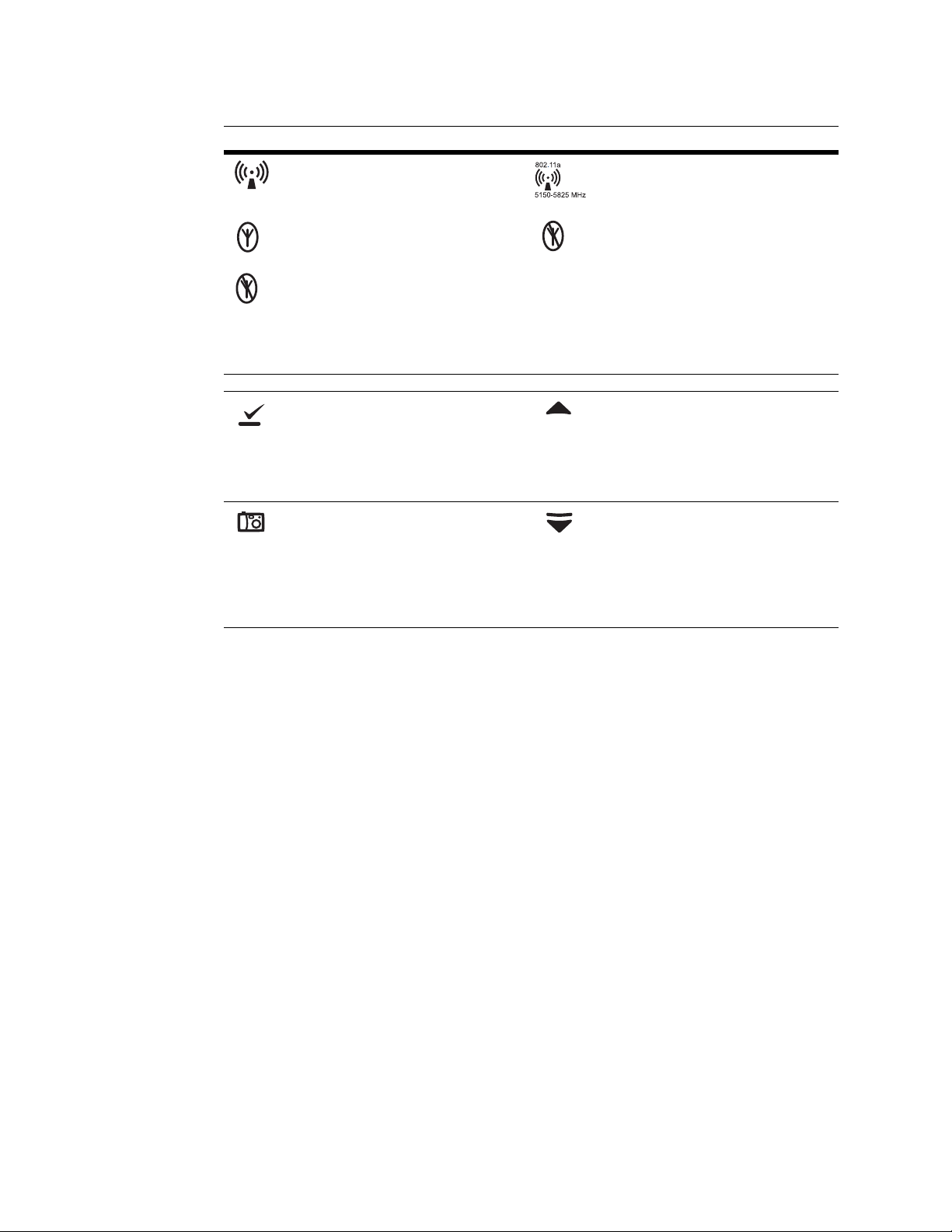
Symbol Definition Symbol Definition
Non-ionizing electromagnetic radiation. This
device contains an approved RLAN module
frequency 2402 to 2480 MHz
The monitor is connected to Acuity The monitor is not connected to Acuity
(Flashing) The monitor is searching for a
connection to Acuity
Monitor Front Panel Keys
Select Key and Silence Patient Alarm/
Equipment Alert Key- Selects the choice
highlighted on the menu. During patient alarms,
silences the tone at the monitor and at Acuity (if
connected) for 90 seconds. During equipment
alerts, silences or acknowledges (dismisses) the
alert.
Snapshot Key - When connected to Acuity,
pressing this key sends Acuity a snapshot print
to the Acuity central station printer. A total of
21 seconds of patient numeric and waveform
data (14 seconds of history, 7 seconds after the
key is pressed) will be sent to the printer. See
”Snapshot key” on page 10 for more
information.
Non-ionizing electromagnetic radiation. This
device contains an approved RLAN module
frequency 5150 to 5825 MHz
Scroll Up Key and Reset Alarm Tone KeyScrolls up menus on the display. During patient
alarms, resets the tone at the monitor and at
Acuity (if connected).
Scroll Down Key and Main Menu Key- Pressing
this key scrolls down menus on the display, or
causes the Main Menu to appear if no menu is
displayed.
Page 8
4 Chapter 1 General information Welch Allyn Micropaq Monitor
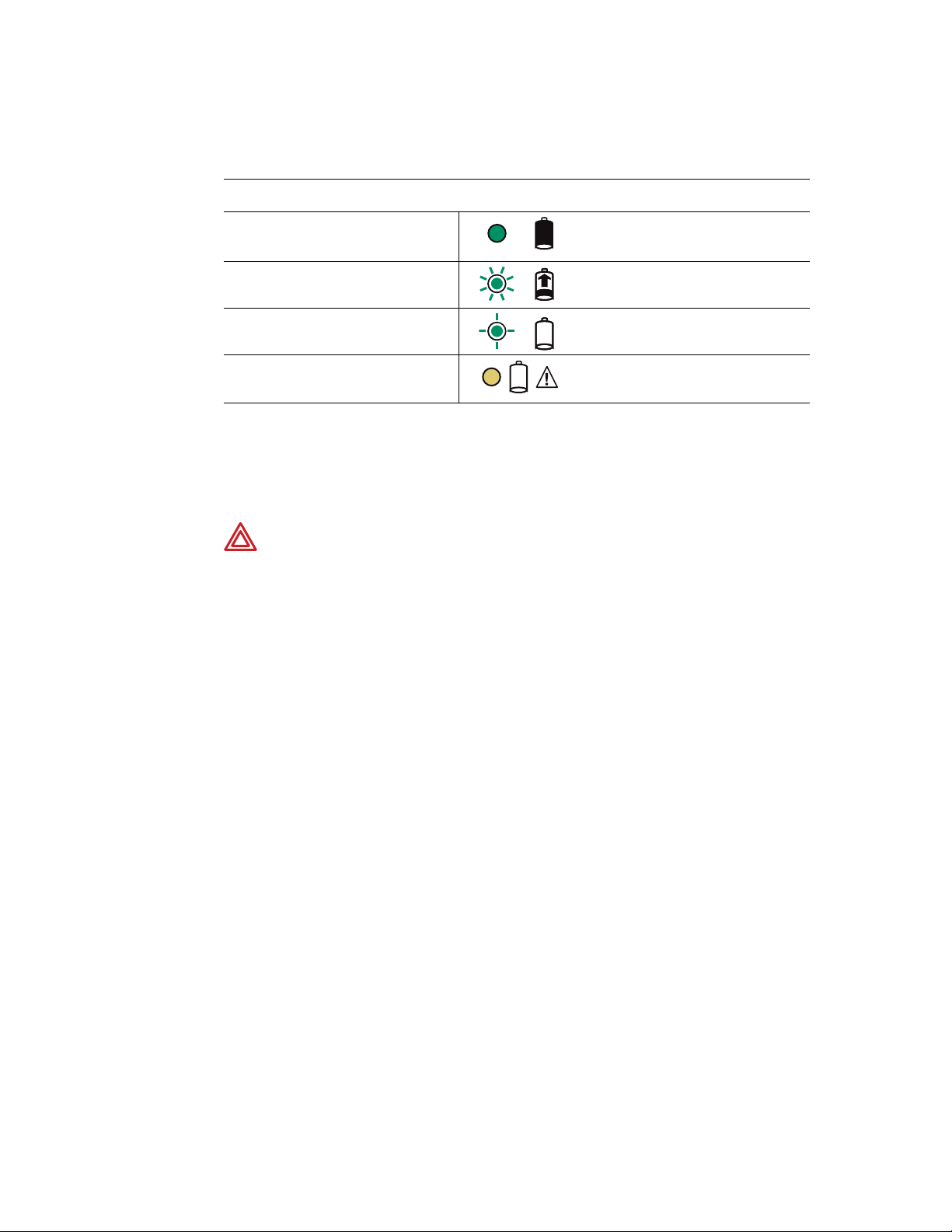
Battery charger labels and LEDs
Eight-bay battery charger
(008-0651-XX)
Green LED on continuously Battery is fully charged.
Green LED flashing
Green LED flashing very slowly Battery detected and waiting to be charged.
Yellow LED on continuously Something is wrong with the battery or the
kj
General warnings and cautions
Familiarize yourself with all warnings and cautions before using the monitor.
WARNING When considering a treatment protocol that involves wireless
communication of patient data, be sure to recognize some limitations inherent
in wireless communications. When the monitor is not connected to the
network:
• There are no patient alarms or alerts at the Acuity Central Station.
• Acuity does not perform arrhythmia and ST analysis on the patient data
and does not generate related alarms.
• Patient data is not saved.
WARNING Do not try to monitor neonatal patients with the monitor. The
monitor is intended for adult or pediatric patients. It is not intended for use with
pediatric patients (or infants) weighing less than 22 lbs (10 kg).
Battery is charging.
charger. (See ”Battery Status and Possible
Response” on page 44.)
WARNING Always check the patient mode at Acuity when monitoring a new
patient. The patient mode determines default alarm limits and internal algorithm
settings.
WARNING The monitor may not meet its performance specifications if stored
or used outside the specified temperature and humidity ranges.
WARNING Do not connect more than one patient to a monitor. Do not connect
more than one monitor to a patient.
WARNING During defibrillation, keep the discharge paddles away from ECG
and other electrodes, as well as other conductive parts in contact with the
patient.
WARNING Do not operate this product in the presence of flammable
anesthetics or other flammable substances in combination with air, oxygenenriched environments, or nitrous oxide; explosion can result.
WARNING Do not use the monitor in a Magnetic Resonance Imaging (MRI)
suite or a hyperbaric chamber. Such use can cause fire or explosion resulting in
patient injury and monitor damage.
Page 9

Directions for use Chapter 1 General information 5
WARNING Magnetic Resonance (MR) Safety. This monitor is designated Not
MR Safe, as defined in the ACR Guidance for Safe MR Practices, 2007. Do not
place this monitor in Zones 3 or 4, in MR environments for which Zones have
been established and marked in accordance with the Guidance. In MR
environments for which Zones have not been designated, do not place this
monitor into a magnetic field with field strength larger than the field strength
that your facility permits to exist in areas that are accessible by personnel,
patients, and guests without MR safety precautions. Failure to follow these
precautions creates a risk that the magnetic field will damage the monitor,
causing it to overheat and potentially burn patents and cause a fire. The damage
to the monitor caused by exposure to magnetic fields may be immediate or
latent. If the damage is latent, it can cause the monitor to overheat at some time
subsequent to its exposure to the magnetic field.
WARNING Electronic equipment that emits strong electromagnetic or radio
frequency signals can cause electrical interference with monitor operation. This
interference may distort the ECG signal, thereby preventing accurate rhythm
analysis. Avoid operating this device near equipment of this type.
WARNING Exposure to Radio Frequency (RF) radiation. To comply with Federal
Communications Commission (FCC) RF exposure requirements, this device
shall be used in accordance with the operating conditions and instructions
provided in this manual, including the section ”Install the carrying pouch” on
page 28.
WARNING Pacemaker signals can differ from one pacemaker to the next. The
Association for Advancement of Medical Instrumentation (AAMI) cautions that
“in some devices, rate meters may continue to count the pacemaker rate during
occurrences of cardiac arrest or some arrhythmias. Do not rely entirely upon rate
meter alarms. All pacemaker patients should be kept under close or constant
observation.” See ”ECG specifications” on page 53 for disclosure of the
pacemaker pulse rejection capability of this instrument.
WARNING This wireless medical device was tested and, when used with a
metal-free accessory between the monitor and the patient, complies with FCC
RF Exposure (SAR) guidelines. The use of accessories containing metal may not
ensure compliance with FCC RF exposure guidelines. Specific Absorption Rate
(SAR) is a measurement of radio frequency energy. The FCC permits a
maximum SAR value of 1.6 mW/g. The highest SAR value for this patient
monitor, when worn by a patient in accordance with the directions for use, is
0.560 mW/g.
WARNING Military radars are allocated as primary users in the bandwidths
between 5.25 - 5.35 GHz and 5.47 to 5.725 GHz. In the event a radar signature
is detected, the Access Point moves to a new channel, which can temporarily
interrupt patient monitoring. If the device is operated near a military radar, the
radar could cause damage to the device.
WARNING Changes or modifications not expressly approved by Welch Allyn
could void the purchaser’s authority to operate the equipment. This product
does not contain any user serviceable components. Any unauthorized product
changes or modifications will invalidate Welch Allyn’s warranty and all applicable
regulatory certifications and approvals.
WARNING Motion artifact can affect the accuracy of patient vital sign
measurements. Minimize patient motion whenever possible.
Page 10

6 Chapter 1 General information Welch Allyn Micropaq Monitor
WARNING For patients with a pacemaker, position the monitor to maintain a
minimum 6-inch distance between the monitor and pacemaker. Immediately
turn the monitor off and provide appropriate patient care if you have any reason
to suspect that the monitor is interfering with the pacemaker. The Health
Industry Manufacturers Association recommends this minimum 6-inch distance
between a hand-held wireless radio and a pacemaker, which is consistent with
the independent research by, and recommendations of, Wireless Technology
Research.
WARNING Make frequent electrical and visual checks on cables, sensors, and
electrode wires. All cables, sensors, and electrode wires must be inspected and
properly maintained and in proper working order to allow the equipment to
function properly and protect patient safety.
WARNING Avoid electrosurgery burns at monitoring sites by ensuring proper
connection of the electrosurgery return circuit so that the return paths cannot be
made through monitoring electrodes and probes.
WARNING Use of ECG and SpO
cables not specified by Welch Allyn may
2
negate defibrillator protection and risk patient injury.
WARNING Use of Masimo LNOP
®
sensors/cables will not provide protection
in accordance with IEC defibrillation standards when used with this device.
WARNING To ensure patient safety, the conductive parts of the ECG
electrodes (including associated connectors) and other patient-applied parts
should not contact other conductive parts, including earth ground, at any time.
WARNING Use only accessories supplied by Welch Allyn or recommended in
the Welch Allyn Products and Accessories booklet (810-0409-XX). The monitor
will only meet the listed specifications when using accessories listed by Welch
Allyn. Use accessories according to your facility’s standards and the
manufacturer’s recommendations. Always refer to the manufacturer’s Directions
for Use.
WARNING As with all medical equipment, carefully route the patient cabling to
reduce the possibility of patient entanglement or strangulation. Use the supplied
garment clips to secure the cable properly.
WARNING When positioning the monitor pouch on the patient, make sure the
straps do not entangle the patient’s neck or cause choking. Make sure the straps
do not restrict the movement of the patient’s limbs or create a hazard when
walking or moving.
WARNING If a product has been dropped or severely abused, send it to a
qualified service person to confirm proper operation.
WARNING Do not use the pulse oximeter as a replacement or substitute for
ECG-based arrhythmia analysis.
Caution Do not autoclave the monitor. Autoclave accessories only if the
manufacturer’s instructions clearly approve it. Many accessories can be severely
damaged by autoclaving.
It is possible for the monitor to detect a problem that prevents the monitor from operating
properly. If this occurs, the monitor displays an error message and error number. Report
such errors to Welch Allyn. The monitor should be serviced only by a Welch Allyn service
technician while under warranty. Contact Welch Allyn for information about post-warranty
period service.
Page 11
Directions for use Chapter 1 General information 7
Introducing the monitor
The monitor is a patient-worn vital signs monitor for use by adult or pediatric ambulatory
patients.
• One or two ECG channels displayed
• Up to 2 ECG leads displayed at the monitor:
I, II, III, V, aV
• Up to 7 ECG leads displayed at Acuity:
I, II, III, V, aV
• One ECG lead displayed at the monitor and
at Acuity: Fixed lead II with 3-lead cable, or
5-lead cable with only RA, LA and LL
electrodes attached.
• Pulse oximetry (SpO
408 only)
• Two-way wireless communication within
Welch Allyn’s FlexNet network
• LCD for display of ECG waveforms, SpO
and heart rate/pulse rate data, and
messages from Acuity
• Standalone operation with patient alarms
when out of range of the network
• Patient alarm limits that can be set at the
monitor or at Acuity
• Configurable formats for single- or dual-waveform ECG display
• Internal antenna
• Snapshot key
• Lightweight (less than two pounds with battery)
• Rugged and tolerant of brief water exposure
• Rechargeable battery
• Sleep mode to extend battery life
• Your model may be shipped with an attached identification number on the front of the
monitor.
, aVL, or aVF with 5-lead cable
R
, aVL, or aVF with 5-lead cable
R
) monitoring (Model
2
2
Model 406
Model 408
ECG monitoring
ECG monitoring and either one of two pulse oximetry (SpO2) monitoring options:
•SpO
•SpO
with Masimo® SET® technology, indicated by:
2
with NELLCOR® OxiMax® technology, indicated by:
2
Page 12
8 Chapter 1 General information Welch Allyn Micropaq Monitor
HR
SpO2
80
97
FlexNet Network
Micropaq monitors
Access Points
To Other
Access
Points
To Other Acuity
Central Stations
Acuity Central Station
HR
SpO2
80
97
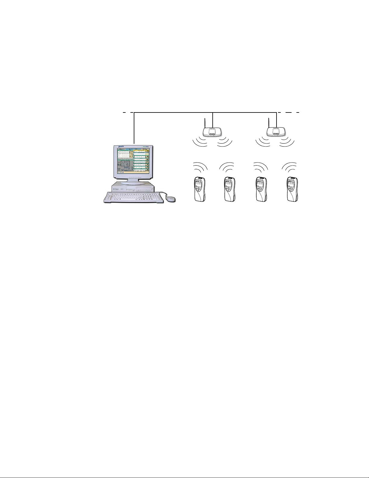
Understanding the monitor and the FlexNet Network
The monitor is intended to operate with an Acuity® Central Station as part of Welch Allyn’s
FlexNet network. FlexNet allows multiple devices to communicate through hardwired
Ethernet networks and Wireless Local Area Networks (WLANs). The Acuity Central
Station provides the primary display and entry of patient data for a patient connected to
the monitor.
HR
SpO2
80
97
HR
SpO2
80
97
Each patient-worn monitor supports two-way communication with an Acuity Central
Station through an access point in the FlexNet network. The access point is a digital radio
transceiver that connects to the FlexNet network. During monitoring, the monitor sends
the patient data to Acuity. Acuity and the monitor continuously analyze the data. Acuity
provides appropriate alarm or alert messages at the Central Station and other network
devices such as a hallway message panel and the monitor itself. Acuity also stores the
patient data for viewing or report printing.
If the monitor is moved out of range or loses communication with the FlexNet network
and Acuity, it continues to monitor the patient and display patient data. While not
communicating with Acuity, the monitor continues to generate local patient alarms or
alert messages. Patient data is not stored and Acuity does not perform waveform analysis
or generate arrhythmia messages while the monitor is not communicating with Acuity.
When the monitor is returned to within range of the FlexNet network, it automatically
reconnects to Acuity.
Page 13
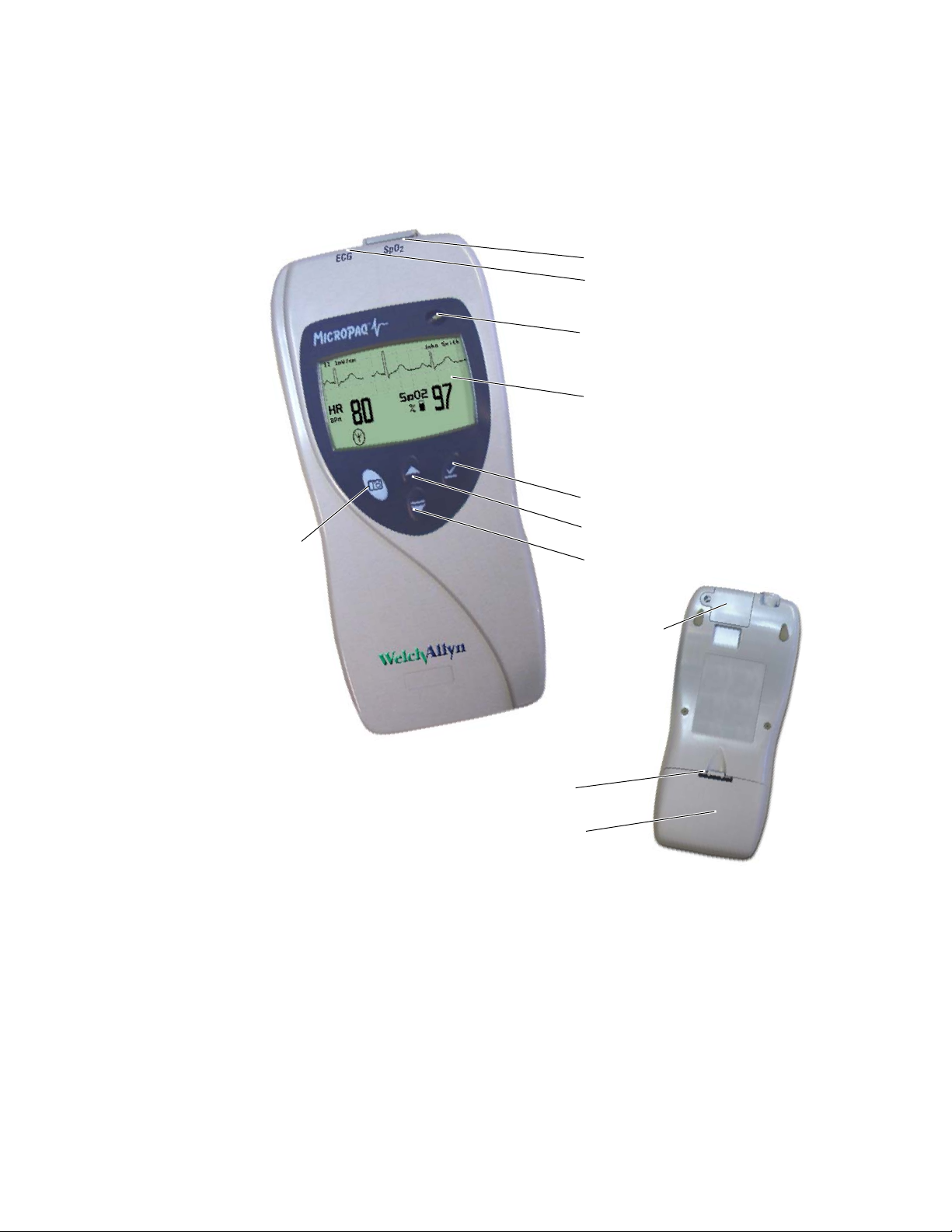
Directions for use Chapter 1 General information 9
SpO2 Connector
ECG Connector
Visual Alarm Indicator
Liquid Crystal Display
Snapshot key
Scroll Up Key and Reset Patient Alarm Tone Key
Scroll Down Key and Main Menu Key
Select Key and
Silence Patient Alarm/
Equipment Alert Key
Back
Battery pack latch
Battery
SpO
2
connector clip
(model 408) or
cover (model
406)
Monitor features
Controls and connectors
Page 14

10 Chapter 1 General information Welch Allyn Micropaq Monitor
Note
Note
Visual alarm indicator
Green Flashes slowly during normal operation.
Red Flashes during patient alarm, remains on continuously when alarms are
silenced or suspended.
Yellow Flashes during an equipment alert or while not connected to the network.
Remains on continuously if the operator suspends an alert at Acuity for 90
seconds or acknowledges (dismisses) a low battery alert from the monitor
or Acuity.
The flashing green LED indicates that the monitor is connected to the network
but not necessarily connected to a patient. If the monitor is actively monitoring a
patient, the green LED indicates no alarms or alerts are detected.
Audible alarm indicator
Beeps to indicate a patient alarm, and beeps faster for life-threatening arrhythmia
alarms (see ”Patient alarm and equipment alert specifications” on page 58).
Snapshot key
Beeps to indicate when the equipment needs attention. This beep tone is slower than
patient alarm tones (see ”Patient alarm and equipment alert specifications” on
page 58).
Volume can be configured as high, low, or off (configured at Acuity).
Volume can be configured differently for network connection or stand-alone operation
(configured at Acuity).
When connected to Acuity, pressing this key sends a snapshot of the patient’s
numeric and waveform data to the Acuity Central Monitoring System. Depending on
how Acuity is configured, this will cause Acuity to print a 21-second snapshot (14
seconds of history, 7 seconds of data after the button is pressed) to the Acuity central
station printer.
Snapshot is the default selection of the monitor. However, the connected
monitor will inherit the configuration previously defined by Acuity. For example,
if Acuity has defined the Snapshot key to respond with a Nurse Call function and
a new monitor is introduced to the system, the Snapshot key definition will
remain as Nurse Call.
For more information about using the Acuity Central Monitoring System, refer to
Acuity Directions For use.
Scroll Up key and Reset Patient Alarm Tone key
Scrolls up menus on the display.
Resets a silenced patient alarm tone.
Page 15

Directions for use Chapter 1 General information 11
Note
Scroll Down key and Main Menu key
Scrolls down menus on the display.
Displays the Main Menu.
Select key and Silence Patient Alarm/Equipment Alert key
Selects the choice highlighted on the menu.
During patient alarms, silences the tone at the monitor and Acuity (if connected) for
90 seconds. During equipment alerts, silences or acknowledges (dismisses) the alert
at the monitor and Acuity.
Battery
Insert the battery to turn on power. Remove the battery to turn off power. (While the
battery is removed, the monitor does not perform patient monitoring.)
If you do not use END TELE to disconnect from the network as described
above, the Acuity Central Station generates a DROPOUT equipment alert at
Acuity.
If you want to monitor this same patient at a later time, you will need to reselect
the patient name from the monitor or confirm the patient ID at Acuity.
Recharge the battery while it is removed from the monitor. (See ”Recharge a battery”
on page 43.)
To order a new battery, see ”Battery Status and Possible Response” on page 44.
Page 16

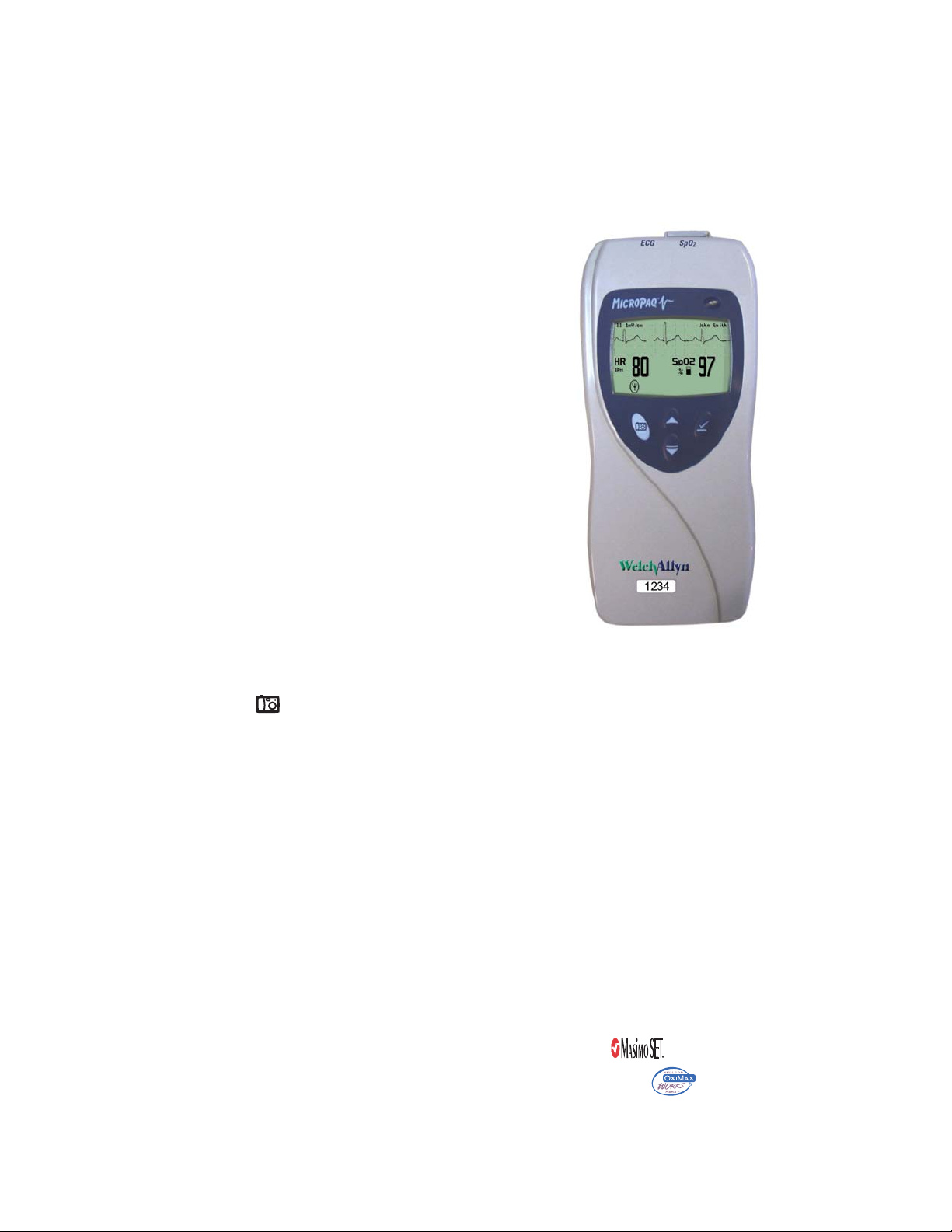
12 Chapter 1 General information Welch Allyn Micropaq Monitor
Patient name as entered at
Acuity.
If the patient name has not
been entered, the monitor
displays the last four digits of
the monitor serial number, such
as:
ID:6472
SpO2 numeric data is a
percentage value.
HR indicates the heart
rate is from ECG.
PR (pulse rate) is
displayed if SpO
2
is active
and ECG is not (pulse rate
is derived from SpO2).
If the monitor detects
a vital sign outside
the measurable range,
it displays:
- - - (below the range)
+ + + (above the range).
ECG lead is selectable
Low battery icon flashes to
indicate monitor will shut off in
30 minutes or less.
Indicates the monitor
is connected to
Acuity.
Waveform scale is
selectable
Indicates one or
more patient alarms
are disabled (off).
ECG waveform is displayed
when active.
Dashed lines indicate the
monitor detects a pacemaker
signal (display of pacer
detection can be enabled or
disabled at Acuity)
This symbol indicates the monitor is not
communicating with Acuity:
Flashing indicates the monitor is associated
with an access point, but not communicating
with Acuity.
Continuous on indicates the monitor is not
communicating with an access point or Acuity.
Symbol is displayed at the
monitor whenever the
Snapshot key is pressed.
SpO2 pulse amplitude indicator
(not proportional to pulse
volume)
Display
Although the Acuity Central Station is the primary location for viewing patient data, the
monitor provides information to support patient care.
Display sleep mode
In order to extend battery life, the display becomes blank after two minutes if no keys are
pressed. The display becomes active again if an alarm or alert occurs, a key is pressed,
the initial Acuity connection occurs, a cable is inserted, or an electrode is attached.
The display will not become blank if a patient alarm is occurring, an Acuity message is
displayed, or the monitor is in Demo mode or Service mode.
Page 17
Directions for use Chapter 1 General information 13
Press to select or change the highlighted choice.
Press to move through the menu.
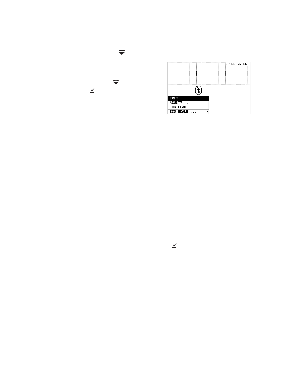
Main Menu
When you first press , the Main Menu appears:
EXIT Exit the Main Menu (the menu disappears).
ACUITY... Access the Acuity Menu with network options. The Acuity Menu
is only accessible while connected to Acuity.
EXIT Exit all menus and return to the monitoring
screen.
END TELE Discontinue monitoring a patient.
NEW ROOM Reassign a patient to a new room in the same
unit.
TRANSFER Transfer a patient to a new room in a new unit.
NEW PATIENT Assign the monitor to a new patient.
PATIENT INFO Display patient information such as ID, name,
unit and room.
Whenever the monitor is connected to Acuity and you select
ACUITY... from the Main Menu, the monitor displays the message
ACUITY CONTACTED to confirm that Acuity has been contacted.
The monitor continues to display this message until Acuity
responds, or you press to acknowledge the message and clear
the screen. If the monitor detects an alarm or alert, it clears the
screen to display the appropriate alarm or alert message. The
length of time required for Acuity to respond to your selection at
the monitor can vary widely depending on the amount of network
traffic and other conditions.
ECG LEAD... Access a menu to change the ECG 1 or ECG 2 lead selection (I, II,
III, aV
, aVL, aVF, or V). Available vectors depend on the connected
R
electrodes.
Page 18

14 Chapter 1 General information Welch Allyn Micropaq Monitor
Note
ECG SCALE... Change the scale of the ECG waveform. If two waveforms are
displayed, both have the same scale.
1 WAVEFORM There are four possible ECG waveform display selections:
1 WAVEFORM the default selection
2 WAVEFORMS
5 SECONDS
FULL SCREEN
Pressing changes to the next selection. This change does not
take effect until after you exit the Main Menu. See ”Display” on
page 12 for descriptions.
LIMITS... Enter the Alarm Limits Menu (”Customize patient alarm limits at
the monitor” on page 37) and change alarm limits.
SYSTEM
INFORMATION
Display information about the network connection and SpO
module.
SERVICE MENU Enter Service Mode for a demonstration mode (Demo, see
”Demonstration mode” on page 17) or service functions for
technicians. Service Mode is not available if any cables are
plugged in.
To restrict access to the Main Menu, a Menu Lock option can be configured for
the monitor at the Acuity Central Station. When the Menu Lock is enabled, the
operator must press and hold down and for two seconds to gain access
to the Main Menu. The Menu Lock is disabled if the monitor loses
communication with Acuity.
2
Page 19
Directions for use Chapter 1 General information 15
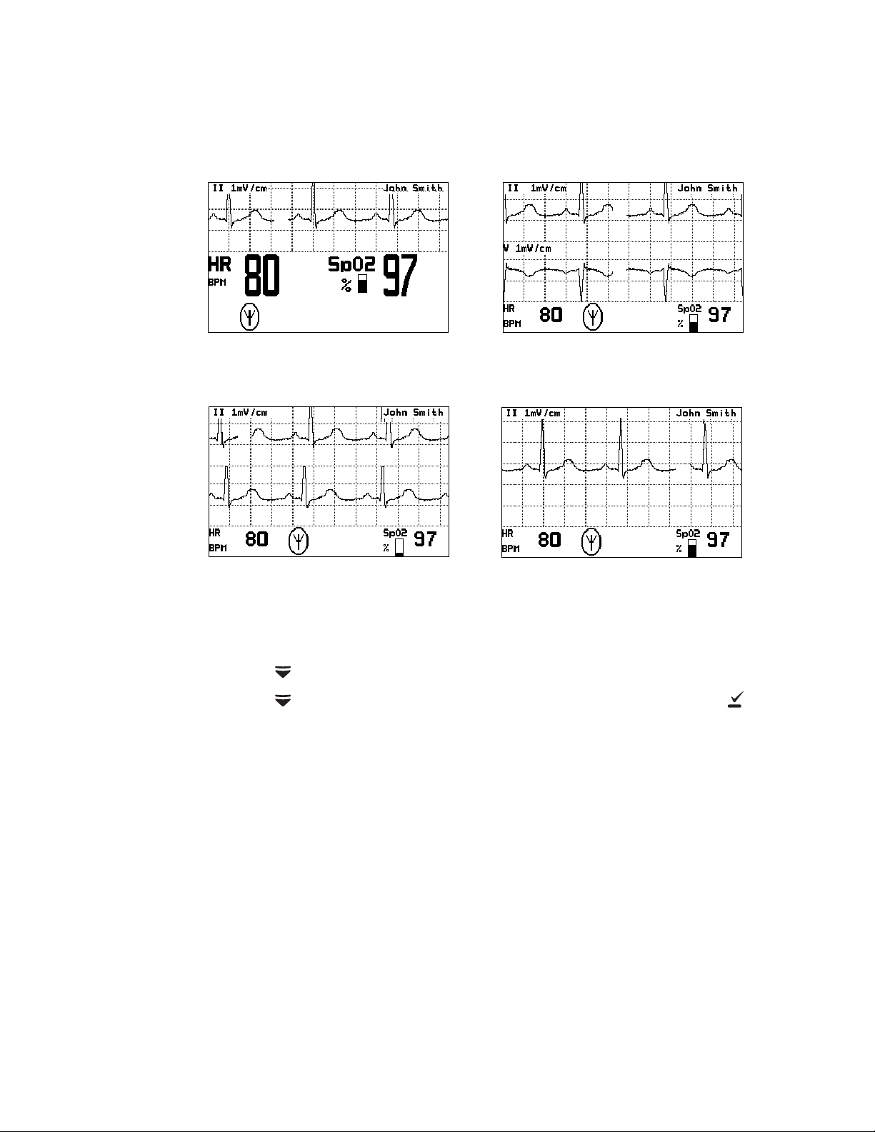
1 Waveform
The single ECG 1 (lead II)
waveform is displayed.
Full Screen
The single ECG 1 (lead II) waveform is
allowed to occupy most of the screen.
2 Waveforms
ECG 1 (lead II) and ECG 2
(lead V) are both displayed.
5 Seconds
ECG 1 (lead II) cascades from
one line to the other.
Waveform options
There are four ECG waveform options as shown:
To change the waveform selection during operation:
1. Press to display the Main Menu.
2. Press as needed to highlight the current waveform selection. Then press as
needed to select the desired display.
Page 20

16 Chapter 1 General information Welch Allyn Micropaq Monitor
Messages from Acuity
The monitor displays messages sent from Acuity as needed, including patient alarms and
equipment alerts. When Acuity messages are displayed, they temporarily override
information displayed on the lower half of the monitor screen.
Accessories
Battery charger (8-battery) Micropaq Directions For use
Battery ECG electrodes
3-lead ECG cable (optional) 5-lead ECG cable
ECG extension cable (optional) Carrying pouch
sensors (Masimo or Nellcor) SpO2 cable (Masimo or Nellcor)
SpO
2
WARNING Use only accessories supplied by Welch Allyn or recommended in
the Welch Allyn Products and Accessories booklet (810-0409-XX). The monitor
will only meet the listed specifications when using accessories listed by Welch
Allyn. Use accessories according to your facility’s standards and the
manufacturer’s recommendations. Always refer to the manufacturer’s Directions
for Use.
Operating settings
The following monitor operating settings can be set at the monitor or at the Acuity Central
Station:
• Patient alarm limit settings (ECG and SpO
• ECG lead and scale selection
• ECG display format
Many other monitor operating settings (such as patient mode and alarms volume) can
only be set at the Acuity Central Station. See ”Operating settings” on page 51 for a list of
all settings and where they are set.
Default settings
When the monitor connects to Acuity for a new patient, the Acuity Central Station
downloads the appropriate default settings stored at Acuity. While the monitor is
connected to Acuity, settings can be changed either at the monitor or at the Acuity Central
Station.
If the monitor is temporarily disconnected from Acuity and the operator changes settings
at the monitor, those settings are transmitted to and stored at Acuity when the monitor
reconnects.
).
2
Page 21
Directions for use Chapter 1 General information 17
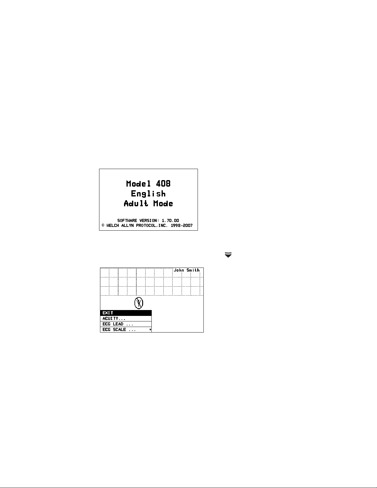
Power-Up Screen
Main Menu
Demonstration mode
You can practice using the monitor with the Demo mode of operation, including
connection to Acuity.
The Demo mode cannot be activated while you are monitoring a patient or if any cables
have been plugged into the monitor. During the Demo mode, the monitor and Acuity
display the message SIMULATION.
To practice with the monitor in Demo mode:
1. Disconnect all patient cables connected to the monitor.
2. Remove the battery (if installed).
3. Insert the battery and watch for the Power-Up screen.
4. After the Power-Up screen disappears, press to display the Main Menu.
Page 22
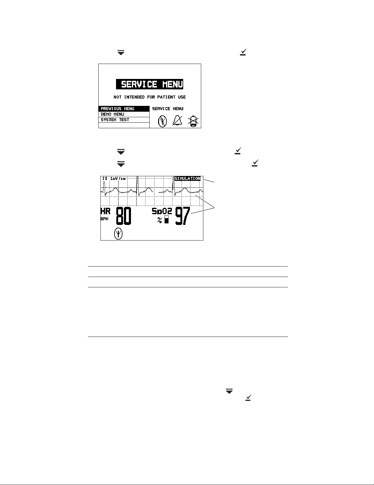
18 Chapter 1 General information Welch Allyn Micropaq Monitor
Service Menu
A simulated waveform and
numerics are displayed.
Demonstration Mode
SIMULATION indicates the
Demo mode is active.
5. Press to highlight SERVICE MENU, then press to display the Service Menu.
6. Press to highlight DEMO MENU, then press to display the Demo Menu.
7. Press to highlight DEMO 1 or DEMO 2, then press to start.
Demo Mode Display Values and Alarm Limits
Display Demo 1 Demo 2
ECG Waveform Normal sinus rhythm,
normal ST
ECG Heart Rate
SpO2 Pulse Rate
Saturation% 97 88 Lower 90
SpO
2
a. Demo 2 will cause patient alarms.
80 125 Lower 50
a
Normal sinus rhythm,
normal ST
Alarm Limits (On)
(not applicable)
Upper 120
Upper 100
8. While in Demo mode you can practice changing settings such as ECG lead selection
and alarm limit adjustment. (These changes only affect the Demo mode and are
erased when you exit the Demo mode.)
9. To change to the other Demo selection, press to display the menu, then scroll
down to highlight TOGGLE DEMO MODE and press .
10. To exit the Demo mode, either insert a patient cable or remove and insert the battery.
The monitor restarts and enters the normal monitoring mode.
Page 23
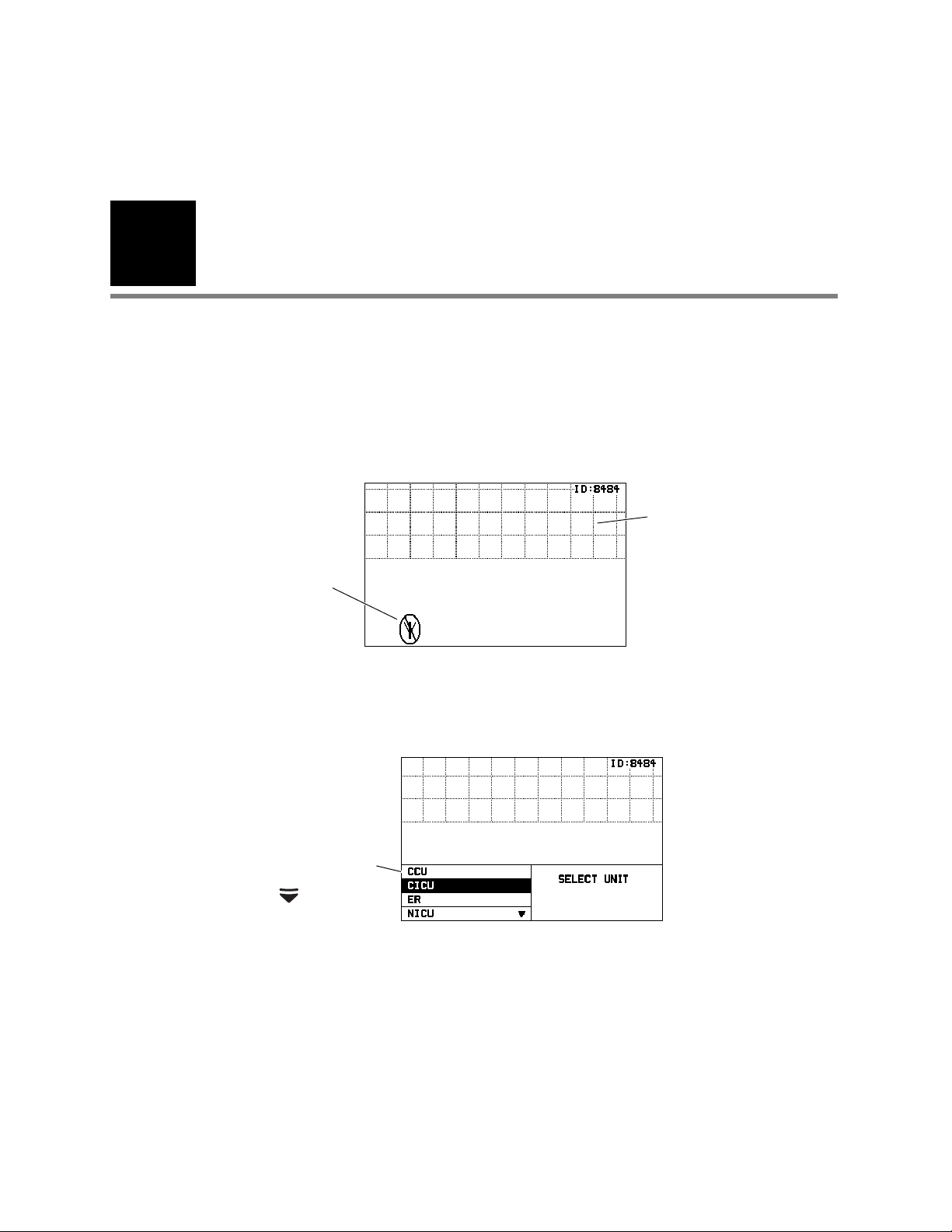
19
If any patient cables are
connected, there will be
some patient data displayed.
The format depends on the
monitor default settings.
Example of Initial Monitor Screen
The monitor is
searching for a
network
connection.
Possible Acuity Unit
selections.
Press to view more.
Example of Acuity Unit Selection
2
Monitoring
Connect a new patient
Connect to the network
1. Insert a battery into the monitor to turn it on. After a few seconds the monitor PowerUp Screen is replaced by an initial monitoring screen.
2. After the network connection is established, the monitor may prompt you to select an
Acuity Unit (if your facility has more than one Acuity unit):
Page 24
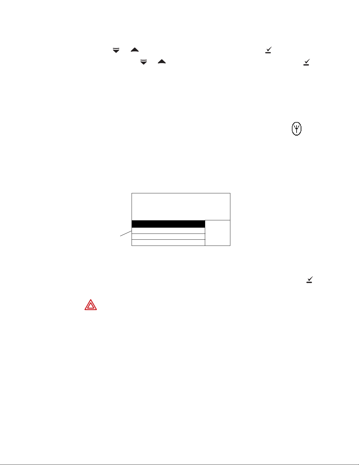
20 Chapter 2 Monitoring Welch Allyn Micropaq Monitor
Note
Network Connection
Symbol
Possible
patients to
select.
Example of Patient List
SELECT
PATIENT
428-02-2392, Hopkins, Bill J
520-29-0319, Phillips, Mary L
532-94-8372, Smith, Frank R
▼
Select Patient at Central
3. Press or to highlight the desired Acuity unit, then press .
When you press or to highlight the desired Acuity unit and then press ,
your selection will begin to flash between normal and reverse video to confirm that
the monitor is communicating your selection to Acuity. You cannot scroll to another
selection during this time. The selection continues to flash until Acuity responds back
to the monitor. Then the monitor displays the next appropriate screen (such as a list of
possible patients). The length of time required for Acuity to respond to your selection
at the monitor can vary widely depending on the amount of network traffic and other
conditions.
Be sure to select an Acuity unit. Even though the monitor is
connected to the network (as indicated by the green LED and
network connection symbol), the Acuity Central Station may not
display any indication of this monitor until after you have selected an
Acuity unit.
4. The monitor displays a list of possible patients.
If your patient has been pre-admitted to the selected Acuity unit, they will be included
in the list.
5. Scroll through the patient list to look for your patient’s name.
• If your patient is not in the list, highlight Select Patient at Central and press .
The patient name will need to be entered later at the Acuity Central Station.
WARNING If you do not select the patient name at the monitor at this time, do
not adjust any alarm limits until after the patient name and ID are confirmed at
Acuity. When the patient name and ID are confirmed at Acuity, Acuity
downloads the default settings and patient alarm limits for that Acuity unit to the
monitor, thereby overriding any previous settings and alarm limits.
At power-up, the monitor retains the most recent patient mode. The patient
mode can only be changed at Acuity. If the patient is being monitored when the
patient mode is changed, there is a brief interruption in the display and recording
of ECG and SpO
patient data.
2
Page 25
Directions for use Chapter 2 Monitoring 21
Possible
rooms to
select.
Example of Room List
SELECT
ROOM
1104A
1104B
1105A
Select Room at Central
▼
• If your patient is in the list, highlight the name and press . Within a few
seconds the monitor displays a list of unassigned rooms.
• If you want to assign the patient to a room, highlight the room and press .
• If you do not want to assign a room at this time, highlight Select Room at
Central and press . The patient room will need to be entered later at the
monitor (see “Reassign a monitored patient to a new room in the same unit” on
page 32) or at Acuity (see “Monitor patient at Acuity” on page 41).
6. If you need to customize alarm limits for your patient, see “Customize patient alarm
limits at the monitor” on page 37.
Perform ECG monitoring
WARNING Motion artifact can cause incorrect heart rate readings. Minimize
patient motion whenever possible.
WARNING If a disconnected lead is in too close proximity to other electrical
devices, it may cause false heart rate readings.
WARNING The monitor does not provide internal arrhythmia analysis.
Therefore, arrhythmias may cause the monitor to display inaccurate heart rates.
WARNING The monitor will show + + + for HR numerics between 301 and
350 beats per minute. Above 350 beats per minute, it may display incorrectly
low heart rates, due to intermittent picking of R-waves.
WARNING Do not use the monitor in a Magnetic Resonance Imaging (MRI)
suite or a hyperbaric chamber. Such use can cause fire or explosion resulting in
patient injury and monitor damage.
WARNING Pacemaker signals can differ from one pacemaker to the next. The
Association for Advancement of Medical Instrumentation (AAMI) cautions that
“in some devices, rate meters may continue to count the pacemaker rate during
occurrences of cardiac arrest or some arrhythmias. Do not rely entirely upon rate
meter alarms. All pacemaker patients should be kept under close or constant
observation.” See “ECG specifications” on page 53 for disclosure of the
pacemaker pulse rejection capability of this instrument.
Page 26

22 Chapter 2 Monitoring Welch Allyn Micropaq Monitor
WARNING For patients with a pacemaker, position the monitor to maintain a
minimum 6-inch distance between the monitor and pacemaker. Immediately
turn the monitor off and provide appropriate patient care if you have any reason
to suspect that the monitor is interfering with the pacemaker. The Health
Industry Manufacturers Association recommends this minimum 6-inch distance
between a hand-held wireless radio and a pacemaker, which is consistent with
the independent research by, and recommendations of, Wireless Technology
Research.
WARNING High-intensity radio frequency (RF) energy from external sources,
such as an improperly connected electrosurgical unit, can induce heat into
electrodes and cables which can cause burns on the patient. Reading errors and
damage to equipment may also result. This hazard can be reduced by (1)
avoiding the use of small ECG electrodes, (2) selecting ECG electrode
attachment points remote from the surgical site and from the electrosurgical
return electrode, (3) using electrosurgical return electrodes with the largest
practical contact area, and (4) assuring proper application of the electrosurgical
return electrode to the patient.
WARNING Verify patient mode at Acuity. Incorrect patient mode may result in
inaccurate heart rates and inappropriate alarm settings.
WARNING To help prevent injury, use the provided garment clips to route the
ECG cables away from the patient’s head.
WARNING Use of ECG cables with loose or faulty detachable lead wires may
cause erratic behavior of the ECG waveform due to intermittent ECG lead wire
connections.
WARNING To ensure patient safety, the conductive parts of the ECG
electrodes (including associated connectors) and other patient-applied parts
should not contact other conductive parts, including earth ground, at any time.
Caution To protect the monitor from damage during defibrillation, for accurate
ECG information, and for protection against noise and other interference, use
only ECG electrodes and cables specified or supplied by Welch Allyn (these
cables have the required current-limiting resistors). Follow recommended
application procedures.
Caution Do not use an ECG cable longer than 10 feet (3 meters). If the nominal
length of the ECG cable, including extensions, exceeds this length, the monitor
is not guaranteed to meet published electromagnetic compatibility (EMC)
performance specifications.
• Even though the monitor contains fully isolated patient-connected circuitry, it has not
been specially designed for direct application on a patient’s heart.
• Use only with accessories provided or recommended in the Welch Allyn Products and
Accessories booklet (810-0409-XX).
• Severe artifact and interference (such as defibrillation interference) can cause the
waveform to move off the display for a few seconds before it is restored.
Page 27

Directions for use Chapter 2 Monitoring 23
Flashing circle indicates the
lead is not connected.
Left ArmRight Arm
Left Leg
Right Leg
Perform 5-Lead ECG monitoring
1. Inspect the ECG cable and replace it if it shows any signs of wear, breakage, or
fraying. Plug the cable into the monitor.
2. Select electrode sites on the patient.
Choose flat areas; avoid fatty or bony areas and major muscles.
3. Shave or clip hair from electrode sites, thoroughly clean skin, and lightly rub dry.
You may use soap and water, isopropyl alcohol or special skin preparation pads. To
avoid allergic reactions to electrodes, refer to the electrode manufacturer’s directions.
4. If you are using pre-gelled electrodes, make sure the electrode date is not expired and
the gel is intact and not dried out. For best results, use only silver/silver chloride
electrodes.
If you are using ungelled electrodes, apply a 1/4- to 1/2-inch mound of gel over the
electrode contact area.
For best product performance and measurement accuracy, do not use stainless steel
needle electrodes, squeeze bulb electrodes, or electrodes with dissimilar metals. Due
to polarization, such electrodes can generate offsets beyond the monitor’s
capabilities. Do not use electrodes from more than one manufacturer on the same
patient.
5. Attach lead wires to the electrodes before applying them to the patient. Apply the
electrodes to the patient in the proper locations.
If the monitor detects that some lead wires are not properly connected, the monitor
displays a chest diagram and indicates which leads are disconnected.
The locations of the circles displayed on the monitor for each lead are fixed, and are
not affected by the exact placement of the electrodes on the patient. For example,
the C lead can be placed on the patient in any one of the V1-V6 locations desired, but
will only be displayed on the monitor in the location shown above.
6. After leads are properly connected, confirm that the monitor displays the ECG
waveform, heart rate, and other patient data.
To change the ECG lead selection, press to display the Main Menu. Then press
Scroll Down to highlight ECG LEAD . . . , then highlight ECG 1 or ECG 2 and press
to change the lead.
Page 28

24 Chapter 2 Monitoring Welch Allyn Micropaq Monitor
Note
3-Lead ECG application with the 5-Lead ECG cable
Be aware that there are some inherent limitations with this application,
especially when compared to 5-lead ECG monitoring. These limitations include
the restriction to only one displayed lead, ECG lead II. Because only one
displayed lead is available (ECG lead II), factors such as a poor electrode
connection at RA, LA, or LL can significantly affect performance. To overcome
these limitations, the 5-lead ECG monitoring is preferred.
The monitor’s 3-lead ECG monitoring is only available for use with Acuity
software versions 6.1 or later.
You can perform 3-lead ECG monitoring in a similar manner as 5-lead ECG monitoring. You
may use the 5-lead ECG cable with detachable electrode lead wires, and connect only the
lead wires and electrodes for RA, LA, and LL. Refer to the Welch Allyn Product and
Accessories booklet (810-0409-XX) for part numbers.
Follow these steps:
1. Pe r f o r m Step 1 through Step 4 on page 23 as described for 5-lead ECG monitoring.
2. Before attaching electrodes to the patient, attach only lead wires for RA, LA, and LL to
the 5-lead ECG trunk cable and to the electrodes. Make sure that lead wires for C and
RL are DETACHED from the 5-lead ECG trunk cable.
3. Apply the electrodes for RA, LA, and LL to the patient in the proper locations.
The monitor displays the chest diagram with two circles blinking confirming that the C
and RL electrodes are not connected.
4. Observe the monitor and visually confirm that within about 30 seconds, the two
circles disappear and the monitor displays the ECG waveform, heart rate, and other
patient data.
Be aware that if you connect the C or RL lead wires to the 5-lead ECG trunk cable and
apply the C or RL electrodes to the patient, the monitor defaults to 5-lead ECG
monitoring and does not enable 3-lead ECG monitoring. To enable 3-lead ECG
monitoring, you must disconnect the ECG cable from the monitor for a few seconds,
and then begin this procedure again.
Page 29

Directions for use Chapter 2 Monitoring 25
Note
Be aware that only ECG lead II is available for display with the monitor’s 3-lead ECG
monitoring. No other ECG lead selections are available.
WARNING Do not try to perform this 3-lead ECG monitoring with any 5-lead
ECG cable that does not have detachable electrode lead wires as described
above. Attempting to perform this procedure with a 5-lead ECG cable which has
lead wires cut off or hanging loose and not connected to the patient would
present a shock hazard to the patient or clinician.
3-Lead ECG application with the 3-Lead ECG cable
Be aware there are some inherent limitations with this application, especially
when compared to 5-lead ECG monitoring. These limitations include the
restriction to only one displayed lead, ECG II lead. Because only one displayed
lead is available (ECG lead II), factors such as poor electrode connection at RA,
LA, or LL can significantly affect performance. To overcome these limitations,
the 5-lead ECG monitoring is preferred.
The monitor’s 3-lead ECG monitoring is only available for use with Acuity
software versions 6.1 or later.
Refer to the Welch Allyn Product and Accessories booklet (810-0409-XX) for part numbers.
Follow these steps:
1. Pe r f o r m Step 1 through Step 4 on page 23 as described for 5-lead ECG monitoring.
2. Attach lead wires to the electrodes before applying them to a patient.
3. Apply the electrodes for RA, LA, and LL to the patient at the proper locations. If the
monitor detects one of the lead wires is not properly connected, it will display a chest
diagram indicating which lead is disconnected.
4. Observe the monitor and visually confirm it displays the ECG waveform, heart rate,
and other patient data.
Be aware that only ECG lead II is available for display with the monitor’s 3-lead
monitoring. No other ECG lead selections are available. The monitor will not detect
the presence of a 3-lead cable until two or more of its leads are connected to the
patient.
3-Lead ECG application with the 3-Lead ECG cable and cable extension
This combination functions the same way as the 3-lead ECG application with the 5-lead
cable. For electromagnetic compatibility (EMC) reasons, do not use an ECG cable and
extension cable length of more than approximately 10 feet total.
Page 30

26 Chapter 2 Monitoring Welch Allyn Micropaq Monitor
Perform SpO2 monitoring
WARNING Oxygen saturation measurements using pulse oximetry are highly
dependent on proper placement of the sensor and patient conditions. Patient
conditions such as shivering and smoke inhalation may result in erroneous
oxygen saturation readings. If pulse oximetry measurements are suspect, verify
the reading using another clinically accepted measurement method, such as
arterial blood gas measurements on a co-oximeter.
WARNING Use only accessories as listed in the Welch Allyn Products and
Accessories booklet (810-0409-XX). Use only Masimo accessories and sensors
with the Masimo SpO
the Nellcor SpO
2
when using accessories listed by Welch Allyn.
WARNING Use of Masimo LNOP
in accordance with IEC defibrillation standards when used with this device.
WARNING Tissue damage can be caused by incorrect application or use of a
sensor (e.g., wrapping the sensor too tightly, applying supplemental tape, failing
to periodically inspect the sensor site, leaving a sensor on too long in one place).
Refer to the Directions for Use provided with each sensor for specific
instructions on application and use, and for description, warnings, cautions, and
specifications.
option. Use only Nellcor accessories and sensors with
2
option. The monitor will only meet the listed specifications
®
sensors/cables will not provide protection
WARNING Sensors exposed to ambient light while not applied to a patient can
exhibit semi-normal saturation readings. Be sure the sensor is securely placed
on the patient and check its application often to ensure accurate readings.
WARNING Inaccurate measurements may be caused by venous pulsations.
WARNING The pulse oximeter can be used during defibrillation, but the
readings may be inaccurate for a short time.
WARNING The pulse oximeter should NOT be used as an apnea monitor.
WARNING A very sudden and substantial change in pulse rate can result in
erroneous pulse rate readings. Be sure to validate the patient data and patient
condition before intervention or change in patient care.
WARNING Interfering Substances: Carboxyhemoglobin may erroneously
increase readings; the level of increase is approximately equal to the amount of
carboxyhemoglobin present. Methemoglobin may also cause erroneous
readings. Dyes, or any substances containing dyes, that change usual arterial
pigmentation may cause erroneous readings.
Page 31

Directions for use Chapter 2 Monitoring 27
1. Attach the SpO2 sensor to the patient according to the manufacturer’s directions for
use, observing all warnings and cautions.
Each SpO
sensor is designed for application to a specific site on the patient within a
2
certain size range. To obtain optimal performance, use an appropriate sensor and
apply it as described in the sensor’s directions for use.
If excessive ambient light is present, cover the sensor site with opaque material to
block the light. Failure to do so may result in inaccurate measurements. Light sources
that can affect performance include surgical lights (especially those with a xenon light
source), bilirubin lamps, fluorescent lights, infrared heating lamps, and direct sunlight.
If NIBP will be monitored while using SpO
than the SpO
sensor to help reduce unnecessary SpO2 alarms. For optimal
2
measurements, avoid placing the SpO
, place the NIBP cuff on a different limb
2
sensor on the same limb as an arterial
2
catheter or intravascular line.
Loss of pulse signal can occur if the sensor is too tight, there is excessive ambient
light, an NIBP cuff is inflated on the same limb as the sensor, there is arterial
occlusion proximal to the sensor, the patient is in cardiac arrest or shock, or the
patient has hypotension, severe vasoconstriction, severe anemia, or hypothermia.
2. Inspect the SpO
cable. Replace it if it shows any signs of wear, breakage, or fraying.
2
Plug the cable into the sensor and the monitor.
3. After the cable is connected, confirm that the monitor displays SpO
data within a
2
few seconds.
4. If excessive patient movement interferes with measurements, consider the following
possible solutions:
• be sure the sensor is secure and properly applied
• use a new sensor with fresh adhesive backing
• select a different type of sensor
• move the sensor to a less active site
The SpO
system is designed to work satisfactorily during normal patient motion.
2
Page 32

28 Chapter 2 Monitoring Welch Allyn Micropaq Monitor
Install the carrying pouch
WARNING As with all medical equipment, carefully route the patient cabling to
reduce the possibility of patient entanglement or strangulation. Use the supplied
garment clips to secure the cable properly.
WARNING When positioning the monitor pouch on the patient, make sure the
straps do not entangle the patient’s neck or cause choking. Make sure the straps
do not restrict the movement of the patient’s limbs or create a hazard when
walking or moving.
Adult carrying pouch
The Adult Carrying Pouch is intended for ambulatory adult
patients. It is not intended for use while the patient is in bed.
1. Put the carrying pouch on the patient and insert the monitor.
2. Carefully arrange the pouch and monitor on the patient to
avoid bruising or other skin injuries.
To maximize the monitor’s wireless transmission range,
always make sure that the monitor display is facing out and
away from the patient’s body.
Pediatric carrying pouch
The Pediatric Carrying Pouch is intended for ambulatory pediatric
patients (40 to 80 lbs., 18 to 36 kg.). It is not intended for use
while the patient is in bed.
1. Insert the monitor into the pouch.
2. Carefully arrange the pouch and the monitor on the patient to
avoid bruising or other skin injuries.
To maximize the monitor’s wireless transmission range,
always make sure that the monitor display is facing out and
away from the patient’s body.
Page 33

Directions for use Chapter 2 Monitoring 29
Note
Monitor a patient out of range of Acuity
While out of range of Acuity, the monitor continues to monitor the patient and provide
local HR/PR and SpO2 alarms or alerts at the monitor as needed.
When the patient wearing the monitor goes out of range of Acuity, do the following:
1. A DROPOUT equipment alert occurs at the Acuity Central Station. Acknowledge the
alert at Acuity.
2. An equipment alert occurs at the monitor with this message:
ACUITY CONNECTION LOST
Depending on how the monitor is configured (as controlled by Acuity), this alert can
also cause the monitor to emit audible alert tones.
If tones are enabled, the authorized person should press on the monitor to
acknowledge (dismiss) the alert and silence this instance of the alert tone.
The person authorized to press to acknowledge the alert may vary,
depending on the local protocol. Follow the protocol established by your
institution.
When the patient returns within range of Acuity, the monitor automatically reconnects to
Acuity. No clinician intervention is required.
WARNING When the monitor moves out of range of the Acuity network,
communication with Acuity is broken immediately, stopping the communication
of patient vital-signs data. If the monitor is out of range of the Acuity network for
several minutes, the radio enters a low-power state. When the monitor is again
within range of the Acuity network, it can take as long as three minutes to
restore communication with Acuity and resume the communication of patient
vital-signs data.
Page 34

30 Chapter 2 Monitoring Welch Allyn Micropaq Monitor
Note
Acuity Menu
Stop monitoring a patient
If you want to discontinue monitoring the patient, follow these steps.
1. Press to display the Main Menu.
2. Press to highlight ACUITY, then press .
3. Press to highlight END TELE, then press .
4. When the monitor displays the message SAFE TO REMOVE BATTERY, remove the
battery.
If the battery is not removed within 30 seconds, the monitor will automatically try to
reconnect to the network.
5. Disconnect the leads and sensors from the patient.
If you do not use END TELE to disconnect from the network as described
above, the Acuity Central Station generates a DROPOUT equipment alert at
Acuity.
If you want to monitor this same patient at a later time, you will need to reselect
the patient name from the monitor or confirm the patient ID at Acuity.
Page 35

Directions for use Chapter 2 Monitoring 31
Note
Reconnect a recently monitored patient
1. Insert a battery into the monitor to turn on the monitor. Confirm that after a few
seconds the monitor Power-Up Screen is replaced by the initial monitoring screen.
2. The monitor will then present a series of menus and messages requesting you to
provide information about the connection and patient. The actual screens presented
depend on how long the patient has been disconnected. Provide the information as
requested. This may include:
• Select an Acuity unit.
• Select a patient from the patient list.
• Select a patient room from the room list.
If you do not select the patient name or room while connecting the patient, you
will need to do that later at the Acuity Central Station. See “Monitor patient at
Acuity” on page 41 for more information.
• To perform ECG monitoring, see “Perform ECG monitoring” on page 21.
• To perform SpO
monitoring, see “Perform SpO2 monitoring” on page 26.
2
Page 36

32 Chapter 2 Monitoring Welch Allyn Micropaq Monitor
New Room Selection
Reassign a monitored patient to a new room in the same unit
If a patient is being monitored and you want to assign them to a new room in the same
unit, follow these steps.
1. Press to display the Main Menu.
2. Press again to highlight ACUITY and press to display the Acuity Menu
screen.
3. Press to highlight NEW ROOM, then press .
.
Within a few seconds the monitor displays a list of all available rooms, including the
patient’s current room.
• If you decide not to change the patient’s current room assignment, press (the
patient’s current room is the default selection in the list).
• To assign the patient to a new room, highlight the room and press .
• If you want to cancel the patient’s current room assignment, but do not want to
assign a new room at this time, you can highlight Select Room at Central and
press . You can then assign the room later from the Acuity Central Station, or
you can repeat this procedure and assign a new room from the monitor.
Page 37

Directions for use Chapter 2 Monitoring 33
Transfer a Patient
Transfer a monitored patient to a new room in a different unit
If a patient is being monitored and you want to assign them to a new room in a different
unit, follow these steps.
1. Press to display the Main Menu.
2. Press again to highlight ACUITY and press to display the Acuity Menu
screen.
3. Press to highlight TRANSFER, then press .
Within a few seconds the monitor displays a list of units.
4. Press to highlight the new unit, then press .
The patient is not monitored at Acuity during the short time required by Acuity to
process the transfer to the new unit (typically less than one minute). However, the
patient continues to be monitored by the monitor.
(If the selected unit is currently not available, the monitor displays an appropriate
message; press to acknowledge the message and cancel the transfer.)
5. After the patient is assigned to the new unit, the monitor displays a list of unassigned
rooms. (The patient’s previous unit and room assignment is cancelled.)
• To assign the patient to a new room, highlight the room and press .
• If you decide not to assign the patient to a new room at this time, you can
highlight Select Room at Central and press . You can then assign the room
later from the Acuity Central Station, or you can assign a new room from the
monitor later using the procedure on “Reassign a monitored patient to a new
room in the same unit” on page 32.
Page 38

34 Chapter 2 Monitoring Welch Allyn Micropaq Monitor
Select a New Patient
Reassign the monitor to a new patient
If you want to discontinue monitoring a patient and reconnect the monitor to a new
patient, follow these steps.
1. Press to display the Main Menu.
2. Press again to highlight ACUITY and press to display the Acuity Menu
screen.
3. Press to highlight NEW PATIENT, then press .
The monitor then presents a series of menus and messages requesting you to
provide information about the connection and patient. The actual screens presented
depend on how the Acuity System is configured.
Provide the information as requested. This may include:
• Select an Acuity unit.
• Select a patient from the patient list. (After you select a new patient, all
monitor operating settings are reset to the Acuity System default power-up
settings.)
• Select a patient room from the room list.
If you do not select the patient name or room while connecting the patient, you will
need to do that later at the Acuity Central Station. See “Monitor patient at Acuity” on
page 41 for more information.
• To perform ECG monitoring, see “Perform ECG monitoring” on page 21.
• To perform SpO
monitoring, see “Perform SpO2 monitoring” on page 26.
2
Page 39

35
3
Alarms & alerts
About alarms and alerts
Alarms provide a warning about a patient condition (such as a vital sign limit violation).
Alerts provide a warning about an equipment condition that needs attention (such as a
low battery or detached ECG lead).
Alarms and alerts may be detected either by the monitor or by the network. While
connected to the network, alarms or alerts are displayed at the monitor and at the Acuity
Central Station. Alarms have a higher priority than alerts.
Alarm holdoffs
To help minimize false alarms, the monitor briefly delays or “holds off” triggering alarms
for limit violations for HR/PR or SpO
detects that the patient’s vital sign has returned to acceptable limits, the monitor cancels
the alarm holdoff. The next time a vital sign limit is violated, the monitor starts a new
holdoff period.
. After the alarm holdoff period begins, if the monitor
2
Vital Sign Alarm Holdoff Period
HR 3 seconds
% SpO2 or PR 10 seconds
Page 40

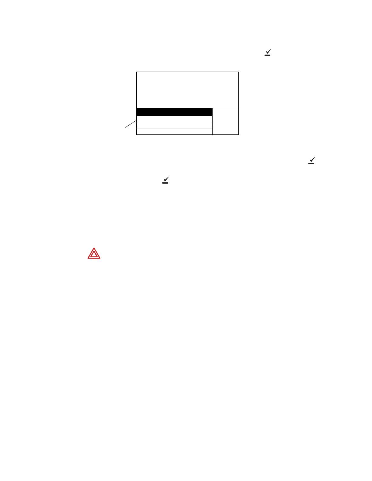
36 Chapter 3 Alarms & alerts Welch Allyn Micropaq Monitor
Press to silence the alarm tone.
Red LED flashes
during alarm.
After the alarm is
silenced (or
suspended at
Acuity), the red
LED is on
continuously.
Flashing numerics
indicate patient
alarm.
Note
Respond to a patient alarm at monitor
When a patient alarm occurs, the monitor produces an audible tone (if audible tones are
enabled). Life-threatening arrhythmia alarms beep at a faster pace than other vital sign
alarms (see “Patient alarm and equipment alert specifications” on page 58). The monitor
also displays a message similar to the following:
1. Check the patient and provide appropriate care.
2. To silence the alarm tone at the monitor and the Acuity Central Station for 90
seconds, press .
While the alarm tone is silenced, visual alarm indications continue, and the red
alarm indicator on the monitor changes from a flashing display to a continuous
display.
If the alarm condition still exists after 90 seconds, the alarm tone resumes.
If you silence an alarm at the monitor and another patient alarm or an equipment
alert occurs during the silence period, the tone resumes at the monitor. At
Acuity, only life-threatening arrhythmia alarms interrupt the silence period.
If you suspend an alarm at Acuity, only life-threatening arrhythmia alarms interrupt
the silence period at the monitor and Acuity.
To access the Main Menu during silencing, press .
Page 41

Directions for use Chapter 3 Alarms & alerts 37
Alarm limits can be adjusted
for HR/PR and SpO
2
.
Select + or - to change the limit.
3. To reset the alarm tone at the monitor and Acuity before the 90 seconds has elapsed,
press at the monitor, or press Resume at the Acuity Central Station.
4. After caring for the patient, make sure that the appropriate alarm limits are set and
that alarms are on.
Customize patient alarm limits at the monitor
WARNING If the patient’s name has not yet been assigned to the monitor, do
not adjust any alarm limits until after the patient name and ID are confirmed at
Acuity. When the patient name and ID are confirmed at Acuity, Acuity
downloads the default settings and patient alarm limits for that Acuity unit,
thereby overriding any custom alarm limits that were set at the monitor before
selecting the patient.
1. Press to display the Main Menu.
2. Press to highlight LIMITS, then press to display the Alarm Limits Adjust
Menu:
3. To change an alarm limit, press or to highlight the desired limit, then press
to display the Threshold Adjustment Menu:
• Scroll and select the + or - selections to change the limit as desired.
• To turn the highlighted limit on or off, scroll to ON/OFF and press .
Page 42

38 Chapter 3 Alarms & alerts Welch Allyn Micropaq Monitor
Note
The monitor has detected that
the ECG cable has been
disconnected from the
monitor.
WARNING If you turn off any alarm limits, be sure to restore the appropriate
alarm limits before you resume monitoring. Only life-threatening arrhythmias will
be indicated at the monitor and Acuity (if connected) when alarms are turned off.
4. To change other limits, scroll to PREVIOUS MENU, press , then select another
limit to change.
5. When you have completed all changes, scroll to PREVIOUS MENU, then EXIT on the
Alarm Limits Adjust Menu and press to return to the normal monitoring screen.
While the monitor is connected to Acuity, settings can be changed either at the
monitor or at Acuity.
Respond to an equipment alert at the monitor
When the network or the monitor detects an equipment problem, the monitor produces a
an audible alert tone (if audible tones are enabled). Equipment alerts beep at a slower
pace than patient vital sign alarms (see “Patient alarm and equipment alert specifications”
on page 58).
The monitor also displays a flashing yellow light (LED) and an equipment alert message
similar to the following:
1. In this instance, press to acknowledge (dismiss) the alert tone and clear the
message.
If the message says “PRESS TO SILENCE,” when you press , the tone is
silenced for 90 seconds instead of dismissed.
If the monitor displays a chest diagram with a missing lead flashing, you can press
to silence the tone.
Some alerts do not give you the option to acknowledge the alert or silence the tone.
For these alerts, to remove the message and tone, you must correct the problem.
Page 43

Directions for use Chapter 3 Alarms & alerts 39
Note
2. If possible, determine what caused the problem and correct it.
After you press to acknowledge or silence some types of alerts, the yellow
LED remains on (either flashing or steady yellow) until you correct the problem.
For low battery alerts and no Acuity connection alerts, specific icons also flash.
For a list of possible messages and suggested responses, see “Alert messages and
display information” on page 40.
Page 44

40 Chapter 3 Alarms & alerts Welch Allyn Micropaq Monitor
Alert messages and display information
Message and Display
Possible Cause(s) and Suggested Response
Information
LOW BATTERY The monitor will shut down within approximately 30 minutes or less due to a low
battery.
• Replace the battery as soon as possible.
VERY LOW BATTERY The monitor will shut down within approximately 5 minutes or less due to a low
battery.
• Replace the battery as soon as possible.
BATTERY TOO LOW
SHUT DOWN IN PROGRESS
The battery is so low the monitor has to shut down operation.
• Replace the battery immediately.
ACUITY CONNECTION LOST The monitor is not connected to the network.
• Press to acknowledge and silence the tone and cancel the message. While
disconnected from the network, the off-network icon and the yellow LED
continue to flash.
NOTE: The monitor will continue to attempt to reconnect until it is successful.
EXCESSIVE ECG OFFSET
REPLACE ELECTRODES
a
Chest icon is displayed with
flashing ECG electrode(s).
The monitor detects poor ECG electrode contact.
• Check and replace ECG electrodes as needed.
The monitor detects that one or more ECG electrodes are disconnected.
a
• Check and replace or reconnect electrodes as needed.
NO ECG CABLE DETECTED • If the ECG cable has been intentionally removed from the monitor, press to
cancel the alert tone.
• If the ECG cable has been unintentionally removed, plug it back into the monitor.
Check the patient and monitor to make sure ECG monitoring resumes properly.
• It is normal for this alert to appear with a 3-lead ECG cable when two or more of
its leads are disconnected from the patient. Reconnect the disconnected lead
wires.
NO SPO2 SENSOR DETECTED The SpO
• If disconnection is intentional, press to acknowledge and silence the tone.
sensor has been disconnected for more than 5 seconds.
2
• If disconnection is not intentional, reconnect the sensor or replace the sensor and
reconnect.
a
DEFECTIVE SPO2 SENSOR
or
UNRECOGNIZED SPO
SENSOR
2
<key name> KEY STUCK
a
The SpO2 sensor is either defective or not recognized.
• Replace the SpO
a
sensor with a new, compatible SpO2 sensor.
2
During the power-up self test, the monitor detected that a key is stuck ( , , ,
or ). This can happen if you accidentally press a key down before the Main Menu
is displayed during power-up.
• Remove and then reinsert the battery to power up again and see if the key is still
stuck. If it is, contact your biomedical engineering department.
System Error
Thread: <nnn>
Error ID: <nnn>
The monitor may have experienced difficulty connecting to the network, network
loading issues may be present, or a hardware component of the monitor may have
failed.
• Contact your biomedical engineering department to troubleshoot the problem.
a. This alert message can be acknowledged from Acuity, but not from the monitor.
Page 45

41
4
Monitor patient at Acuity
While the Micropaq is connected to the FlexNet network, patient data gathered by the
monitor is continuously stored at Acuity. You can access this patient information at the
Acuity Central Station and perform administrative functions, including:
• Admit (and discharge) a patient in the Acuity unit.
• Edit the patient description (name, physician, etc.).
• Review and print patient data such as trends and waveforms.
• Suspend patient alarm tones for 90 seconds and resume the alarm tones
WARNING When the monitor moves out of range of the Acuity network,
communication with Acuity is broken immediately, stopping the communication
of patient vital-signs data. If the monitor is out of range of the Acuity network for
several minutes, the radio enters a low-power state. When the monitor is again
within range of the Acuity network, it can take as long as three minutes to
restore communication with Acuity and resume the communication of patient
vital-signs data.
For more information about using the Acuity Central Workstation, refer to Acuity
Directions For Use.
Page 46

42 Chapter 4 Monitor patient at Acuity Welch Allyn Micropaq Monitor
Page 47

43
Note
5
Maintenance
This section provides information to help operators of the monitor and the battery charger
perform routine maintenance activities such as changing or recharging batteries,
inspection, and cleaning.
Change the battery
1. Remove the depleted battery.
2. Insert a fully-charged battery. Use only batteries supplied by Welch Allyn.
WARNING Before installing a battery, carefully inspect the battery case. If
there are any signs of damage, cracks, or leaks, discard the battery properly and
do not use it.
The Acuity unit can be configured to allow you a short time (typically 30 seconds
or more) to change the monitor battery while the monitor is connected to the
network without causing an Acuity equipment alert. If the monitor is connected
to the network and the battery is removed for longer than the allowable battery
changing time, Acuity generates a DROPOUT equipment alert at the Acuity
Central Station.
Recharge a battery
Eight-bay battery charger
1. On the monitor battery charger (008-0651-XX), choose an empty battery well where
the LED is off.
2. Insert the depleted battery into the battery well.
3. Confirm that the charger displays a flashing green LED by the battery to indicate the
battery is detected or is charging.
4. When the green LED is on continuously, the battery is fully charged. Remove the
battery.
Page 48

44 Chapter 5 Maintenance Welch Allyn Micropaq Monitor
If the yellow LED is on continuously, the battery may have reached the end of its
useful life. Refer to the table below for suggested responses.
Charger LED Battery Charger
Label—LEDs
Green LED on
continuously
Green LED
flashing
Green LED
flashing very
slowly
LED off No battery is detected.
Yellow LED on
continuously
Battery Status and Possible Response
Battery is fully charged.
Battery is charging.
Battery is detected and waiting to be charged.
Something is wrong with the battery or the charger. Remove the battery.
• If the LED goes off, it is probably a battery problem. Insert a new
battery into the same battery well. If the new battery charges correctly,
then the battery has a problem; discard the battery. The battery reorder
number is 008-0647-XX. If the same problem occurs with the new
battery, the charger may need repair. Contact biomedical engineering.
• If the LED does not go off when you remove the battery, it is probably a
charger problem. Unplug the charger power cord, wait at least 5
seconds, then plug in the charger power cord again. Insert a new
battery into the same battery well. If the new battery charges correctly,
then the battery has a problem; discard the battery. If the same problem
occurs with the new battery, the charger may need repair. Contact
biomedical engineering.
The charger can accommodate up to eight batteries. The charger charges a maximum of
four batteries at a time. After a battery begins recharging (as indicated by the green LED
that flashes on one second, off one second), it is typically fully recharged within four hours
at room temperature. After a battery is fully charged, the charger continues to maintain
the full charge on the battery until the battery is removed. Leaving a fully-charged battery
in the charger will not harm the battery.
Remove batteries from the battery charger if the battery charger will be disconnected
from ac power for more than a few days. Do not block the cooling vents at the rear of the
battery charger.
The monitor battery charger only charges four batteries at a time. A battery is not fully
charged until the green LED is on continuously. Do not remove a battery until it is fully
charged, or displays a battery fault.
WARNING The monitor battery is Lithium Ion. Do not incinerate, submerge,
crush, disassemble, or autoclave. If a battery has been submerged in liquid,
discard the battery properly; do not try to recharge or reuse the battery. Do not
short the battery terminals. Do not try to connect the battery to any device
except the monitor or the monitor battery charger. Do not expose to high
temperature (above 60° C or 140° F). Use only the specified monitor battery
charger.
Page 49

Directions for use Chapter 5 Maintenance 45
Note
Inspect the monitor, batteries, battery charger, and accessories
WARNING Be sure to unplug the monitor battery charger power cord from the
electrical power outlet before inspecting the battery charger.
Before cleaning, thoroughly inspect the monitor and all accessories for any signs of
damage, cracks, or improper mechanical function of the keys or connectors. While gently
bending and flexing the cables, inspect for damage, cracks, cuts, abrasions, extreme
wear, exposed wires, or bent connectors. Confirm that the connectors are securely
seated. Remove damaged items from use and report damage or improper function to
your service department. At least every 12 months, be sure to thoroughly inspect the
battery charger case and power cord for damage or extreme wear.
Clean the monitor, batteries, and battery charger
WARNING Unplug the monitor battery charger power cord from the electrical
power outlet before cleaning the battery charger. Exposing the battery charger
to liquids while connected to electrical power could result in electrical shock or
fire.
WARNING Do not autoclave the monitor, battery, or battery charger. Never
immerse the monitor, battery, or battery charger in liquid.
The monitor, battery, and battery charger may be disinfected to comply with
OSHA requirements for cleaning and decontaminating spills of blood and other
body fluids. For more information, refer to the Federal OSHA Standard on
bloodborne pathogens: 29 CFR 1910, 1030, 12/6/91.
1. Wipe the equipment with a nearly dry clean cloth moistened with one of the
approved cleaning solutions listed in “Approved cleaning solutions” on page 46. Do
not use any solution or solution with similar constituents listed in “Prohibited cleaning
solutions” on page 46.
a. Do not allow cleaning solution to accumulate anywhere on the device.
b. Inspect to ensure no cleaning liquid is present in connector openings, latches, or
crevices.
2. After cleaning, thoroughly remove residual cleaning solution by wiping all surfaces
with a clean soft cloth dampened with water.
3. Thoroughly dry all surfaces with warm air.
Page 50

46 Chapter 5 Maintenance Welch Allyn Micropaq Monitor
Clean the accessories
WARNING Do not autoclave the accessories. Never immerse the accessories
in liquid unless the accessory manufacturer explicitly instructs you to do so.
Clean accessories per manufacturer’s instructions.
Approved cleaning solutions
Brand names Generic
a
Wex-cide
Sani Cloth
a. Wex-cide (Wexford Labs, Inc. Kirkwood, MO) is a disinfectant that meets OSHA requirements, is EPA approved, and will not harm
b. Sani-Cloth Wipes are proven effective in 5 minutes or less. Sani-Cloth Wipes are EPA-registered and mee t CDC and OSHA guidelines.
®
b
®
Warm water
Liquid soap
Hydrogen peroxide solution
the outside of the monitor, battery, or battery charger. Wipe away disinfectant after the manufacturer’s recommended period.
They are an adequate substitution for Theracide™ Disinfectants.
Prohibited cleaning solutions
Caution Use only cleaning solutions that are recommended by Welch Allyn for
this equipment. Use of solutions that are not recommended or that have a high
acid content or are otherwise inappropriate can cause damage to the equipment,
including cracking and deterioration of the plastic case. Do not use these
solutions or similar products. If your cleaning solution is not on the approved or
prohibited cleaning solution lists, check the cleaning solution ingredients to
ensure that nothing listed in the prohibited cleaning solutions is a constituent
element. If you are unsure whether a cleaning solution should be used, defer to
the approved cleaning solutions list.
Brand names Generic
Coverage
®
Cidex Plus
™
Freon
Vesphene
®
Enviroquat
Staphene
Misty
Virex
®
®
®
Formula 409
®
Fantastik
®
Ovation
®
TBQ
®
Windex
®
®
®
Butyl alcohol
Denatured alcohol
Acetone
Chlorine bleach solution
70 percent isopropyl alcohol
Trichloroethane
Trichloroethylene
Glutaraldehyde
Page 51

Directions for use Chapter 5 Maintenance 47
Li++
Recycling monitor components
When the battery, monitor, or battery charger reaches the end of its life, recycle it locally
according to national, state, and local regulations. You can also return the battery, monitor,
or charger to Welch Allyn for recycling.
Within the European Union
Do not dispose of this product as “unsorted municipal waste.” Prepare it for
reuse or separate collection as specified by Directive 2002/96/EC, as amended,
of the European Parliament and the Council of the European Union on Waste
Electronic and Electrical Equipment (WEEE).
If the monitor or battery (Li++) is contaminated, this directive does not apply. For more
specific information, see www.welchallyn.com/weee, or contact Welch Allyn Customer
Service.
Recycle monitor batteries (Li++) according to the Directive 91/157/EEC
(Batteries and accumulators containing certain dangerous substances) and
Directive 93/86/EEC (Labelling of batteries and accumulators containing
certain dangerous substances).
Page 52

48 Chapter 5 Maintenance Welch Allyn Micropaq Monitor
Change the network name
This procedure allows you to change the network name assigned to the monitor (as long
as the current network name is one of the pre-set names available in the monitor Network
Name Menu).
WARNING Changing the monitor network name will cause the monitor to restart and seek to connect with the FlexNet network corresponding to the new
name. Do not attempt to change the network name unless you are a qualified
biomedical service engineer or a Welch Allyn employee.
WARNING Ensure that you only change the network name in a non-clinical
environment.
To change the network name:
1. Pr e s s to access the Main Menu, then repeatedly press until SERVICE MENU
is highlighted.
2. Press to display the Service Menu screen.
3. Press and hold and , then press to display the Network Name Menu.
If the current monitor network name is one of the following pre-set names:
com.protocol demo.protocol
com1.protocol com2.protocol
com3.protocol com4.protocol
com5.protocol com6.protocol
com7.protocol com8.protocol
then the monitor displays the following screen
Page 53

Directions for use Chapter 5 Maintenance 49
To change the network name, make sure YES is highlighted, then press to display
the following screen:
Press or to highlight the desired network name, then press . The
monitor automatically turns itself off, then turns on and seeks to connect to a FlexNet
network with the new network name.
If the current network name is a custom name, the monitor displays the following
screen:
You cannot change the network name using the Network Name Menu. Press to
return to the Service Menu. Contact Welch Allyn Technical Support for assistance.
Page 54

50 Chapter 5 Maintenance Welch Allyn Micropaq Monitor
Page 55

51
6
Reference
Operating settings
The following table lists all of the monitor settings and the default settings.
Parameter Set at
Patient Mode
Adult (age 13 years and older)
Pediatric (age greater than 28
days of age or more than 44
weeks gestation up to 12
years)
ECG screen mode (Single, Dual, 5
Sec, or Full Screen)
ECG 1 Lead Selection Yes Yes Yes Yes II
ECG 2 Lead Selection Yes Yes Yes Yes V (or III if no V lead)
ECG Size (Scale) Yes No No Yes 1 mV/cm
Language No No Yes Yes English
Mains Filter (off, 50, or 60 Hz) No No Yes Yes 60
Vital Signs Alarm Volume
(high, low, or off)
With Acuity Connection
Without Acuity ConnectionNoNo
Equipment Alert Volume
(high, low, or off)
With Acuity Connection
Without Acuity ConnectionNoNo
HR/PR Alarm Limits
(Lower, Upper)
SpO
Alarm Limits
2
(Lower, Upper)
Regulatory settings
(U.S., Europe, Japan)
Pacer Detection Enable No Yes No Yes On
Menu Lockout No No Yes No Off
Display Backlight Timeout No No Yes Yes 120 seconds
a. Set by clinician at Acuity Central Station.
b. Set by Acuity System Administrator during system installation.
c. SpO2 alarm limit range depends on the software version of the Acuity System to which the monitor is connected. (See “Heart rate and
arrhythmia analysis option” on page 55 and “Pulse oximetry (SpO
c
Set at Acuity Previous
Monitor
No Yes No Yes Adult
Yes No Yes Yes Single
Yes Yes Yes Yes Adult: 50, 120 bpm
Yes Yes Yes Yes Adult: 90, 100%
No No Yes Yes U.S.
For Each
Patient
No
No
No
No
For Entire
a
Acuity
Unit
Yes
Yes
Yes
Yes
) specifications - Nellcor” on page 57.)
2
b
Setting
Retained at
Monitor at
Power-Up
No
Yes
No
Yes
Monitor Default
Setting
off
high
off
low
Ped: 50, 150 bpm
Ped: 90, 100%
Page 56

52 Chapter 6 Reference Welch Allyn Micropaq Monitor
Specifications
Monitor radio specifications (5 GHz)
Characteristic Specification
FlexNet™ Network 5 GHz orthogonal frequency division multiplexing (OFDM) wireless local area network
(WLAN) and 10/100/1000 base
Modulation OFDM
Output power 40 mW maximum; country-dependent
IEEE standards 802.11a, 802.11e, 802.11h, 802.1X
Monitors per access point 20 (max.)
Caution Some countries restrict the use of 5-GHz bandwidths. The 802.11a radio
in the Micropaq monitor uses only the channels indicated by the access point
with which the radio associates. The hospital IT department must therefore
configure all associated access points to operate within approved domains.
Channel restrictions in the 5-GHz band, by country, are as follows:
-T Ethernet network
Restrictions for use in the 5 GHz bands
Allowed frequency bands
5.15 to 5.25 GHz 36, 40, 44, 48 Austria
5.15 to 5.35 GHz 36, 40, 44, 48, 52, 56, 60, 64 Cyprus, Czech Republic, France,
5.15 to 5.35 GHz
and 5.470 to 5.725 GHz
a. This device may be not be operated outdoors when using the bands 5150 to 5350 MHz (Channels 36, 40, 44, 48, 52, 56, 50, 64).
b. This device must be used with Access Points that have employed and activated a radar detection feature required for European
Community operation in the 5GHz bands. This device will operate under the control of the Access Point in order to avoid operating
on a channel occupied by any radar system in the area. The presence of nearby radar operation may result in temporary interruption
in communications of this device. The Access Point’s radar detection feature will automatically restart operation on a channel free
of radar. You may consult with the local technical support staff responsible for the wireless network to ensure the Access Point
device(s) are properly configured for European Community operation.
c. To remain in conformance with European spectrum usage laws for Wireless LAN operation, the above 5 GHz channel limitations
apply. The user should check the current channel of operation. If operation is occurring outside of the allowable frequencies as
listed above, the user must cease operating the device at that location and consult the local technical support staff responsible
for the wireless network.
d. In Italy the end-user must apply for a license from the national spectrum authority to operate this device outdoors.
a
b
Allowed channel numbers
36, 40, 44, 48, 52, 56, 60, 64, 100,
104, 108, 112, 116, 120, 124, 128,
132, 136, 140
c
Countries
Hungary, Slovakia
Belgium, Bulgaria, Denmark,
Estonia, Finland, Germany, Greece,
Iceland, Ireland, Italy
Liechtenstein, Lithuania,
Luxembourg, Malta, Netherlands,
Norway, Poland, Portugal, Slovenia,
Spain, Sweden, Switzerland, U.K.
d
, Latvia,
Page 57

Directions for use Chapter 6 Reference 53
Monitor radio specifications (2.4 GHz)
Characteristic Specification
FlexNet Network 2.4 GHz Wireless Local Area Network (WLAN) and 10/100 Base-T Ethernet
Frequency
Modulation Frequency Hopping Spread Spectrum (FHSS)
Output Power 100 mW
IEEE 802.11 compliant Yes
Monitors per Access Point 15 (maximum) in most countries. In countries where available frequencies
a. When used within certain countries, authorization for use is restricted as follows:
a
France: The equipment is internally restricted to the 2.448-2.482 GHz frequency range.
Spain: The equipment is internally restricted to the 2.447-2.473 GHz frequency range.
Japan: The equipment is internally restricted to the 2.473-2.495 GHz frequency range.
Italy: Operation requires a user license.
Note: The frequency ranges specified above are subject to geographic-specific regulatory authorities.
network
2.402 to 2.480 GHz
are limited, this number is reduced.
ECG specifications
The ECG channel meets all the requirements for Cardiac Monitors Heart Rate Meters and
Alarms specified ANSI/AAMI EC13-1992, except for Impulse response at the monitor
(section 3.2.9.8 part (c)), and Standardizing Voltage at the monitor and at Acuity (section
3.2.9.9). The channel also meets the American National Standard, Safe Current Limits for
Electromedical Apparatus (ANSI/AAMI ES1-1993).
Characteristic Specification
Connector Hypertronics D01 latching connector
Selectable Leads
5-Lead Cable
3-Lead Application (using 3-lead ECG
cable, or 5-lead ECG cable with
detachable lead wires; only RA, LA,
LL electrodes connected)
Lead Fault Indicator Displayed chest icon with flashing indicator for each electrode
ECG Size (sensitivity) 0.2, 0.5, 1, 2, 4, and 8 mV/cm
Display Sweep Speed 25 mm/sec
Bandwidth
Local display
To Acuity Central Station
Sample Rate 364 Hz (182 Hz with turning point decimation to Acuity Central Station)
Input Protection Electrosurgery and defibrillator protected when used with ECG cables
Electrosurgery interference suppression Included on all vectors.
Lead Fail Sense Current 70 nA dc typical for active leads.
Tall T-wave Rejection Meets AAMI (USA) EC13-1992, section 3.1.2.1.c, up through 1.2 mV
Monitored: II, III, V; Derived: I, aV
Monitored: II
0.5 to 94 Hz independent of patient mode
0.05 to 94 Hz independent of patient mode
specified in the Welch Allyn Products and Accessories booklet (810-0409XX).
140-280 nA dc typical for reference electrode, depending on number of
electrodes attached.
, aVL, aV
R
F
Page 58

54 Chapter 6 Reference Welch Allyn Micropaq Monitor
Characteristic Specification
Common Mode Rejection
FILTER function OFF
FILTER function ON
Input Impedance >2.5 M¾ differential @ 60 Hz
Input Range (ac) 10 mV peak to peak (local display)
Input Range (dc) Up to ±500 mV
System Noise ð30 µV peak-to-peak, RTI
QRS Detector Adult or Pediatric Amplitude Range: 0.22 to 5.0 mV (RTI)
Heart Rate Range
Alarm Limits
Heart Rate Meter Response Time Responds to change in heart rate within 5 to 9 seconds depending on
HR Display Update Interval at monitor 1 second
HR Accuracy ±3 beats per minute or 3%, whichever is greater
Heart Rate Response to ineffectively
paced QRS pattern
Heart Rate Averaging Method Heart rate = 60/ latest average interval in seconds.
Drift Tolerance (AAMI Specification EC131992, 3.2.6.3)
Pacer Pulse Display Pacer indicator shown on screen if PACER display turned ON; pacer spike
Pacer Pulse Rejection Pacer detection range (i.e., will show the dashed vertical marker) for ±3 mV
<1 mV p-p RTI for 10V rms, 50/60 Hz into unbalanced input
<30 µV p-p RTI for 10V rms, 50/60 Hz into unbalanced input
10 mV peak to peak (Acuity Central Station)
Adult Width Range (Duration): 70 to 120 msec
Pediatric Width Range (Duration): 40 to 120 msec
25 to 350 beats per minute (measurement)
25 to 300 beats per minute (display)
25 to 245 beats per minute (lower)
30 to 250 beats per minute (upper)
physiological waveform. (As measured per AAMI standard EC13-1992
clause 4.1.2.1 (f), including 3.1.2.1 parts f. and g. waveforms.) Includes 1
second readout update interval.
Indicates rate of 30 to 46 during AAMI EC13-1992 part 3.1.4.1 part (f) and (g)
tests.
NOTE: AAMI Test 4.1.4 part f and g: Accuracy is affected (i.e., rate
increases) when QRS and pacer spikes are nearly simultaneous as
occasionally is the case during this AAMI test.
For higher heart rates, latest average interval = 7/8 of previous average
interval + 1/8 of latest interval.
For lower heart rates, latest average interval = 3/4 of previous average
interval + 1/4 of latest interval.
Transition rates for choice of formula include hysteresis and are 70 and 80
beats per minute.
80 beats per minute indicated for 80 beats per minute ECG plus drift
waveform
always shown if of sufficient amplitude.
to ±700 mV @ 0.1 ms width, ±2 mV to ±700 mV @ 0.2 to 2 ms pulse width in
electrically quiet environment. Thresholds automatically adjust to reject
repetitive ambient noise. Operates even while pacer indication is disabled.
Will not count as heartbeats approximately 95% of pacemaker pulses
within pacer detection range, with or without AAMI (EC13-1992) tails of 4,
25, 50, 75, or 100 ms decay time constant, whose tail amplitudes are up to
25%, 2mV maximum, whether ventricular only, or A-V sequential pulses
(150 and 250 ms separation), all per AAMI tests 3.1.4.1 and 3.1.4.2
Response to Irregular Rhythm (AAMI Specification EC13-1992, 3.1.2.1. Part e.)
Ventricular Bigeminy (VB) 78 to 81 bpm (80 bpm expected)
Slow Alternating VB 57 to 65 bpm (60 bpm expected)
Rapid Alternating VB 118 to 123 bpm (120 bpm expected)
Bidirectional Systole 88 to 93 bpm (90 bpm expected)
Page 59

Directions for use Chapter 6 Reference 55
Heart rate and arrhythmia analysis option
Method for calculating heart rate
Monitor Determined by monitor (displayed at monitor)
Heart rate = 60 latest average interval in seconds.
For higher heart rates, latest average interval = 7/8 of previous average interval + 1/8 of latest
interval
For lower heart rates, latest average interval = 3/4 (previous average interval) + 1/4 latest interval.
Transition rates for choice of formula include hysteresis and are 70 and 80 beats per minute.
Acuity System with
Arrhythmia Option
Arrhythmia analysis option when connected to Acuity
ST Analysis ST Analysis can be performed for any or all of seven leads, depending on the operator selection.
Determined by Acuity Arrhythmia Option software (displayed at Acuity Central Station)
The beat-to-beat heart rate (HR) value is calculated as follows:
HR = 60000/actual RR (bpm).
Actual RR = time between last detected QRS complex and previously detected QRS complex
(ms).
Average HR is calculated on the basis of the mean RR interval in the last 6 seconds or 8 RR
intervals (whichever is shorter).
The operator can select a measurement offset.
ST segment shifts are recorded in continuous trend data every second. The operator can inspect
trend data to see the duration and elevation or depression for each episode for any time period
recorded. The operator can also inspect a summary of ST segment shift data within tabular trends.
Heart Rate Heart rate information is available in the trend data which can be viewed on the display or printed.
The operator can inspect the trend data to see the lowest, highest, and median (averaged) heart
rates. Trend data also includes the total beats per range of time.
Definition of Pause
Arrhythmia Event
A pause is defined as the R-R interval which is greater than or equal to two times the average R-R.
Page 60

56 Chapter 6 Reference Welch Allyn Micropaq Monitor
Pulse oximetry (SpO2) specifications - Masimo
SpO2 complies with EN ISO 9919:2005.
Characteristic Specification
Saturation (% SpO2)
Range
Resolution
Alarm Limits
Probe Accuracy (Adults, Pediatrics)
No Motion
During Motion
Pulse Rate
Range
Resolution
Alarm Limits
Pulse Rate Accuracy
No Motion
During Motion
Display Update Interval at monitor 1 second
Alarm Hold-Off Time Period 10 seconds; resets if the sensor reports levels within limits before 10
Circuitry Microprocessor controlled
Electrosurgery interference suppression Yes
Sensor Compatibility Compatible only with Masimo sensors listed in the Micropaq monitor
Sensor LEDs
RED Wavelength
INFRARED Wavelength
Sensor Energies (Radiant Power) 0.13 mW to 0.79 mW at 50 mA pulsed
a. SpO2 alarm limit range depends on the software version of the Acuity System to which the monitor is connected.
b. Motion is defined as rubbing and tapping motions at 2 to 4 Hz at an amplitude of 1 to 2 cm and a nonrepetitive motion between 1
to 5 Hz at an amplitude of 2 to 3 cm in induced hypoxia studies in the range of 70-100% SpO
ECG monitor. This variation equals ±1 standard deviation which encompasses 68% of the population.
a
With Acuity 6.0 or higher
With Acuity 5.4X or lower
b
2
1% to 100%
1%
50% to 99% (lower); 51% to 100% (upper)
80% to 99% (lower); 81% to 100% (upper)
70% to 100% ±2 counts
0% to 69% unspecified
70% to 100% ±3 counts
0% to 69% unspecified
26 to 239 beats per minute
1 beat per minute
25 to 245 beats per minute (lower)
30 to 250 beats per minute (upper)
±3 beats per minute
±5 beats per minute
seconds elapses
Automatic self-test of oximeter when powered on
Automatic setting of default parameters
Automatic alarm messages
section of the Welch Allyn Products and Accessories booklet (810-0409-XX).
For probe/sensor compliance to EN ISO 9919:2005, see the Masimo
directions for use.
660 nm (nominal)
905 nm (nominal)
against a laboratory co-oximeter and
2
WARNING Interfering Substances: Carboxyhemoglobin may erroneously
increase readings. The level of increase is approximately equal to the amount of
carboxyhemoglobin present. Dyes, or any substances containing dyes, that
change usual arterial pigmentation may cause erroneous readings.
WARNING Although the SpO
saturation (with Acuity 6.0 software or higher), the SpO
alarm limit range can be adjusted down to 50%
2
performance and
2
accuracy is not specified below 70%.
Page 61

Directions for use Chapter 6 Reference 57
Pulse oximetry (SpO2) specifications - Nellcor
SpO2 complies with EN ISO 9919:2005.
Characteristic Specification
Saturation (% SpO2)
Range
Resolution
Alarm Limits
Probe Accuracy
Pulse Rate
Range
Resolution
Alarm Limits
Pulse Rate Accuracy ±3 beats per minute
Display Update Interval at the monitor 1 second
Alarm Hold-Off Time Period 10 seconds; resets if the sensor reports levels within limits before 10
Circuitry Microprocessor controlled
Electrosurgery interference suppression Yes
Sensor Compatibility Compatible only with Nellcor sensors listed in the Micropaq monitor section
Sensor LED Wavelengths Within 500 to 1,000 nm
Sensor Energies (Radiant Power) Does not exceed 15 mW
a. SpO2 alarm limit range depends on the software version of the Acuity System to which the monitor is connected.
b. Although some of the listed Nellcor sensors can be used with neon ates with other pulse oximetry devices, the monitor is only intended
for use with adult and pediatric patients, not with neonates.
a
With Acuity 6.0 or higher
With Acuity 5.4X or lower
b
(Adults, Pediatrics)
1% to 100%
1%
50% to 99% (lower); 51% to 100% (upper)
80% to 99% (lower); 81% to 100% (upper)
70% to 100% (0% to 69% unspecified)
OxiMax Max-A, Max-AL ±2 counts
OxiCliq N ±2.5 counts
D-YS ±3 counts
DS-100A ±3.5 counts
26 to 239 beats per minute
1 beat per minute
25 to 245 beats per minute (lower)
30 to 250 beats per minute (upper)
seconds elapses
Automatic self-test of oximeter when powered on
Automatic setting of default parameters
Automatic alarm messages
of the Welch Allyn Products and Accessories booklet (810-0409-XX).
For probe/sensor compliance to EN ISO 9919:2005, see the Nellcor directions
for use.
WARNING Interfering Substances: Carboxyhemoglobin may erroneously
increase readings. The level of increase is approximately equal to the amount of
carboxyhemoglobin present. Dyes, or any substances containing dyes, that
change usual arterial pigmentation may cause erroneous readings.
WARNING Although the SpO
saturation (with Acuity 6.0 software or higher), the SpO
alarm limit range can be adjusted down to 50%
2
performance and
2
accuracy is not specified below 70%.
Page 62

58 Chapter 6 Reference Welch Allyn Micropaq Monitor
Patient alarm and equipment alert specifications
Characteristic Specification
Visual Alarm Indicator at the monitor
Flashing GREEN LED
Flashing RED LED
Continuously ON RED LED
Flashing YELLOW LED
Continuously ON YELLOW LED
Audio Tone Locations Monitor
Audio Tone Frequency 2900 Hz
Life-Threatening Arrhythmia Alarm
Tone Pattern
Patient Alarm Tone Pattern
Equipment Alert Tone Pattern
Audio Tone Volume The monitor audio tone volume is configured by the Acuity System to High,
Limits Setable on all parameters
Alarm Control Automatic preset or manual settings
Alarm Priority Highest priority: Patient alarms
Alarm on Tachycardias Most tachycardias will alarm in less than 8 seconds. These include AAMI
Alarm Holdoff Time Period
Acuity-Configurable Audio Alarm Delay
at the monitor
Patient Alarm Tone Silence from the
monitor or Suspend from Acuity
a
Normal operation
Patient alarm
Patient alarms are silenced
An equipment alert or not connected to the network
Equipment alert suspended for 90 seconds at Acuity or low battery alert
acknowledged (dismissed)
Acuity Central Station (when connected)
1 second on, 1 second off
1second on, 2 seconds off
1second on, 4 seconds off
Low, or Off. The monitor can be configured with separate audio tone volume
settings for when it is connected to an Acuity System and when it is not.
Lowest priority: Equipment alerts
3.1.2.1 part f. waveforms. Certain multifocal tachycardias may initially alarm
as "low rate."
HR = 3 seconds
, PR = 10 seconds
% SpO
2
When a monitor is connected to an Acuity System, the audio alarms at the
monitor can be delayed up to 4 minutes and 15 seconds. The delay time is
selected in Acuity software at the time of Acuity installation. Visual alarm
indications are not delayed.
The monitor LED is continuously ON RED and the audio tone is silenced for 90
seconds (non-adjustable).
If original alarm was silenced from the monitor, new patient alarms or
equipment alerts break the silence at the monitor, but only life-threatening
arrhythmia alarms break the silence at Acuity. If original alarm suspended at
Acuity, only life-threatening arrhythmia alarms break the silence at the
monitor and Acuity.
Equipment Alert Acknowledge from the
monitor
Equipment Alert Suspend from Acuity The LED is continuously ON YELLOW and the audio tone is silenced for 90
Patient Alarm Tone Reset from the
monitor or Resume from Acuity
Patient Out of Range; Transmitter
Failure
The LED returns to the pre-alert state (except Low Battery remains
continuously ON YELLOW) and the auditory tone is dismissed.
seconds (non-adjustable).
For a patient alarm tone that has been silenced, resets the tone.
An equipment alert is generated whenever the monitor fails to communicate
to an Acuity System after a connection has been successfully established. In
addition, the “No Acuity” icon is displayed on the monitor display.
Page 63

Directions for use Chapter 6 Reference 59
Characteristic Specification
Transmitter Battery Failure An equipment alert is generated before the monitor battery becomes
exhausted.
a. To help minimize false alarms, the monitor briefly delays or "holds off" triggering both audible and visual alarms for limit violations
for these vital signs. After the alarm hold-off period begins, if the monitor detects that the patient’s vital sign has returned to
acceptable limits, the monitor cancels the alarm hold-off. The next time a vital sign limit is violated, the monitor starts a new holdoff period.
Display specifications
Characteristic Specification
Type Monochrome passive matrix; LCD module
Resolution 320 x 200 pixels
Active Viewing Area 2.26 x 1.41 in. (57.5 x 35.9 mm)
Pixel Pitch 0.0071 in. (0.18 mm)
Pixel Size 0.0065 in. (0.165 mm)
Viewing Angle 6 o’clock position
Display Color black on white
Environmental specifications (with battery installed)
Characteristic Specification
Operating Temperature 0° to 40° C
Shipping and Storage Temperature -20° to 60° C
Operating Altitude -2,000 to 15,000 ft (-610 to 4,572 m)
Shipping and Storage Altitude -2,000 to 40,000 ft (-610 to 12,192 m)
Operating Relative Humidity 15% to 95%, noncondensing per MIL STD 810E, Procedure 1-natural
Shipping and Storage Relative Humidity 15% to 95%, noncondensing per MIL STD 810E, Procedure 1-natural
Drop 1 meter onto vinyl tile over concrete per EN60601-1
Shock 50 g
Vibration, Random 0.02g
Degree of Protection Against Ingress IPX1 Rating, Drip Proof per EN60529: 1991
Electromagnetic Compatibility (EMC) EN60601-1-2: 2001
2
/Hz from 10 to 500 Hz, ramping down to 0.002g2/Hz at 2000 Hz.
Operating 1 hour per axis, 3 hours per test. Designed to meet RTCA DO160D, Category C.
Caution The monitor may not meet performance specifications if it is not used
or stored within these environmental specifications.
Page 64

60 Chapter 6 Reference Welch Allyn Micropaq Monitor
Note
Physical specifications
Protection classifications, all configurations
Characteristic Specification
Type of Protection against Electric
Shock—Monitor Type: CF
Degree of Protection Against Electric
Shock, for Parts Applied to Patients
Recovery time following defibrillator
discharge
Method of Disinfection Not suitable for autoclaving (see cleaning instructions on “Inspect the
Flammable Anesthetics Not suitable for use with flammable anesthetics.
Height 7.80 in (19.8 cm)
Width 3.50 in (8.9 cm)
Depth 1.96 in (4.9 cm)
Weight (including battery)
Model 406
Model 408
Battery operation only
Battery must be recharged in separate battery charger.
IEC EN 60601-1, 2nd Edition
See monitor labels. CF defibrillator protected.
IEC EN 60601-1, 2nd Edition
Less than or equal to 10 seconds
monitor, batteries, battery charger, and accessories” on page 45).
17.0 oz (0.48 kg)
18.6 oz (0.53 kg)
Battery specifications
Characteristic Specifications
Reorder Number
Lithium Ion Battery
2EA Active A
Battery Type Rechargeable, Lithium Ion
Battery Capacity 2 cells, 7.4 V (nominal), 8.4 V (charging), 1800 mA-hr
Battery Weight 4.5 oz (0.13 kg)
Battery Charger External device
Battery Fuse Rating 5 A, 125 V (not user-accessible)
Operating Times on Battery
Battery Recharge Time 4 hours at 25° C (typical)
Battery Lifetime 300 charge/discharge cycles to 70% of original
a. Battery operating times based on these conditions: new fully-charged battery operating at 25° C,
the monitor connected to Acuity, eight patient alarms per hour, minimal motion artifact.
The following factors may reduce battery operating time:
• Amount of time not connected to Acuity.
• Frequency and duration of alarms and alerts.
• Amount of operator activity using monitor keys (activates display).
• Age of battery.
• Amount of motion artifact during SpO
008-0647-XX
Note: Internal electronic overload circuitry is used as
the primary method of protection.
a
Model 406: 25 hrs
Model 408: 10 hrs
capacity (typical)
monitoring.
2
WARNING The monitor battery is Lithium Ion. Do not incinerate, submerge,
crush, disassemble, or autoclave. If a battery has been submerged in liquid,
discard the battery properly; do not try to recharge or reuse the battery. Do not
short the battery terminals. Do not try to connect the battery to any device
except the monitor or the battery charger. Do not expose to high temperature
(above 60° C or 140° F). Use only the specified monitor battery charger.
Page 65

Directions for use Chapter 6 Reference 61
Eight-bay battery charger specifications
Characteristic Specification
Reorder Number
Universal Battery Charger
Active C
Functional Specifications
Capacity Eight charging bays; able to charge four (Lithium Ion) batteries
Protection Classifications
Duty Cycle Continuous
Type of Protection Against Electric
Shock
Degree of Protection Against Harmful
Ingress of Water
Method of Disinfection Not suitable for autoclaving. (See cleaning instructions on “Inspect the
Flammable Anesthetics Not suitable for use with flammable anesthetics.
Environmental Specifications
Operating Temperature 0° to 40° C
Shipping and Storage Temperature -20° to 60° C
Operating Altitude -2,000 to 15,000 feet (-610 to 4,572 m)
Shipping and Storage Altitude -2,000 to 40,000 feet (-610 to 12,192 m)
Operating Relative Humidity 15% to 95%, noncondensing
Shipping, Storage Relative Humidity 15% to 95%, noncondensing
Shock 30 g
Vibration 0.01g
Electromagnetic Compatibility (EMC) EN60601-1-2: 2001
Physical Specifications
Length 15.0 in (38.1 cm)
Width 9.0 in (22.9 cm)
Height 3.6 in (9.1 cm) including feet
Weight 3.5 lb (1.6 kg)
Electrical Specifications
Rated Input 100 V-240 V AC 600 mA, 50/60 ± 3 Hz, Electrical Class I
Rated Fuses T1.25 A/250V, Time-Delay 5x20mm
Rated Output per charging bay
(Continuous)
Charge Time 4 hours typical for fully discharged battery. Automatic charge termination
Output Over-Current Electronic overload protection
Additional Features Detachable power cord
LED Indicators
LED OFF No battery detected.
Flashing GREEN LED
1 sec ON, 3 sec OFF
1 sec ON, 1 sec OFF
Continuously ON GREEN LED Battery is charged.
Continuously ON YELLOW LED Battery or charging bay fault.
a. Per EN 60601-1 unless otherwise stated.
a
008-0651-XX
simultaneously.
Class I, (Protectively Earthed) with Double Insulation
For ordinary, indoor locations only.
monitor, batteries, battery charger, and accessories” on page 45.)
2
/Hz from 5 to 500 Hz, 30 minutes per axis
8.4 V ± 100 mV dc @1 A max.
when charge is completed, or fault detected.
Battery detected, waiting to be charged
Battery is charged
Page 66

62 Chapter 6 Reference Welch Allyn Micropaq Monitor
Page 67

63
7
Compliance
General
The 802.11a Wireless PC Card must be installed and used in strict accordance with the
manufacturer’s instructions as described in the user documentation that comes with the
product.
This product contains encryption. It is unlawful to export out of the U.S. without obtaining
a U.S. Export License.
Federal Communications Commission (FCC)
This device complies with part 15 of the FCC Rules. Operation is subject to the following
two conditions:
• This device may not cause harmful interference.
• This device must accept any interference received, including interference that
may cause undesired operation.
This equipment has been tested and found to comply with the limits for a Class B digital
device, pursuant to Part 15 of FCC Rules. These limits are designed to provide reasonable
protection against harmful interference in a residential installation. This equipment
generates, uses, and can radiate radio frequency energy. If not installed and used in
accordance with the instructions, it may cause harmful interference to radio
communications. However, there is no guarantee that interference will not occur in a
particular installation. If this equipment does cause harmful interference to radio or
television reception, which can be determined by tuning the equipment off and on, the
user is encouraged to try and correct the interference by one or more of the following
measures:
• Reorient or relocate the receiving antenna
• Increase the distance between the equipment and the receiver
• Connect the equipment to outlet on a circuit different from that to which the
receiver is connected
• Consult the dealer or an experienced radio/TV technician for help
The user may find the following booklet prepared by the Federal Communications
Commission helpful:
The Interference Handbook
This booklet is available from the U.S. Government Printing Office, Washington, D.C.
20402. Stock No. 004-000-0034504.
Welch Allyn is not responsible for any radio or television interference caused by
unauthorized modification of the devices included with this Welch Allyn product, or the
Page 68

64 Chapter 7 Compliance Welch Allyn Micropaq Monitor
substitution or attachment of connecting cables and equipment other than specified by
Welch Allyn.
The correction of interference caused by such unauthorized modification, substitution or
attachment will be the responsibility of the user.
Industry Canada (IC) emissions
This device complies with RSS 210 of Industry Canada.
Operation is subject to the following two conditions: (1) this device may not cause
interference, and (2) this device must accept any interference, including interference that
may cause undesired operation of this device.
L’utilisation de ce dispositif est autorisée seulement aux conditions suivantes: (1) il ne doit
pas produire de brouillage et (2) l’ utilisateur du dispositif doit étre prêt à accepter tout
brouillage radioélectrique reçu, même si ce brouillage est susceptible de compromettre le
fonctionnement du dispositif.
This Class B digital apparatus complies with Canadian ICES-003.
Cet appareil numérique de la classe B est conform à la norme NMB-003 du Canada.
European Union
Czech
Danish Undertegnede Welch Allyn erklærer herved, at følgende udstyr RLAN device overholder de
Dutch Bij deze verklaart Welch Allyn dat deze RLAN device voldoet aan de essentiële eisen en aan
English Hereby, Welch Allyn, declares that this RLAN device is in compliance with the essential
Estonian Käesolevaga kinnitab Welch Allyn seadme RLAN device vastavust direktiivi 1999/5/EÜ
Finnish Welch Allyn vakuuttaa täten että RLAN device tyyppinen laite on direktiivin 1999/5/EY
French Par la présente, Welch Allyn déclare que ce RLAN device est conforme aux exigences
German Hiermit erklärt Welch Allyn die Übereinstimmung des Gerätes RLAN device mit den
Greek
Hungarian Alulírott, Welch Allyn nyilatkozom, hogy a RLAN device megfelel a vonatkozó alapvetõ
Italian Con la presente Welch Allyn dichiara che questo RLAN device è conforme ai requisiti
Latvian
Lithuanian Šiuo Welch Allyn deklaruoja, kad šis RLAN device atitinka esminius reikalavimus ir kitas
Malti Hawnhekk, Welch Allyn, jiddikjara li dan RLAN device jikkonforma mal-htigijiet essenzjali u
Portuguese Welch Allyn declara que este RLAN device está conforme com os requisitos essenciais e
Slovak
Slovene Šiuo Welch Allyn deklaruoja, kad šis RLAN device atitinka esminius reikalavimus ir kitas
Welch Allyn tímto prohlašuje, ze tento RLAN device je ve shodě se základními po_adavky a
dalšími příslušnými ustanoveními směrnice 1999/5/ES.
væsentlige krav og øvrige relevante krav i direktiv 1999/5/EF
de overige relevante bepalingen van Richtlijn 1999/5/EC.
requirements and other relevant provisions of Directive 1999/5/EC.
põhinõuetele ja nimetatud direktiivist tulenevatele teistele asjakohastele sätetele.
oleellisten vaatimusten ja sitä koskevien direktiivin muiden ehtojen mukainen.
essentielles et aux autres dispositions de la directive 1999/5/CE qui lui sont applicables
grundlegenden Anforderungen und den anderen relevanten Festlegungen der Richtlinie 1999/
5/EG. (Wien)
ΜΕ ΤΗΝ ΠΑΡΟΥΣΑ Welch Allyn ΔΗΛΩΝΕΙ ΟΤΙ RLAN device ΣΥΜΜΟΡΦΩΝΕΤΑΙ ΠΡΟΣ ΤΙΣ
ΟΥΣΙΩ ΔΕΙΣ ΑΠΑΙΤΗΣΕΙΣ ΚΑΙ ΤΙΣ ΛΟΙΠΕ Σ ΣΧΕΤΙΚΕΣ ΔΙΑΤΑΞΕΙΣ ΤΗΣ ΟΔΗΓΙΑΣ 1999/5/ΕΚ
követelményeknek és az 1999/5/EC irányelv egyéb elõírásainak.
essenziali ed alle altre disposizioni pertinenti stabilite dalla direttiva 1999/5/CE.
Ar šo Welch Allyn deklarē, ka RLAN device atbilst Direktīvas 1999/5/EK būtiskajām prasībām un
citiem ar to saistītajiem noteikumiem.
1999/5/EB Direktyvos nuostatas.
ma provvedimenti ohrajn relevanti li hemm fid-Dirrettiva 1999/5/EC
outras disposições da Directiva 1999/5/CE.
Welch Allyn týmto vyhlasuje, ze RLAN device spĺňa základné po_iadavky a všetky príslušné
ustanovenia Smernice 1999/5/ES.
1999/5/EB Direktyvos nuostatas.
Page 69

Directions for use Chapter 7 Compliance 65
Spanish Por medio de la presente Welch Allyn declara que el RLAN device cumple con los requisitos
Swedish Härmed intygar Welch Allyn att denna RLAN device står I överensstämmelse med de
esenciales y cualesquiera otras disposiciones aplicables o exigibles de la Directiva 1999/5/CE
väsentliga egenskapskrav och övriga relevanta bestämmelser som framgår av direktiv 1999/
5/EG.
Electromagnetic compatibility
Special precautions concerning electromagnetic compatibility (EMC) must be taken for all
medical electrical equipment. This device complies with IEC EN 60601-1-2:2001.
• All medical electrical equipment must be installed and put into service in
accordance with the EMC information provided in this document and the
Micropaq Monitor Directions For Use.
• Portable and mobile RF communications equipment can affect the behavior of
medical electrical equipment.
The monitors and battery charger comply with all applicable and required standards for
electromagnetic interference.
• It does not normally affect nearby equipment and devices.
• It is not normally affected by nearby equipment and devices.
• It is safe to operate the monitor in the presence of high-frequency surgical
equipment.
• However, it is good practice to avoid using the monitor in extremely close
proximity to other equipment.
Page 70

66 Chapter 7 Compliance Welch Allyn Micropaq Monitor
Monitor
Monitor - Guidance and Manufacturer’s Declaration—Electromagnetic Emissions
The Model 4XX Series Monitor is intended for use in the electromagnetic environment specified below. The customer or
the user of the monitor should assure that it is used in such an environment.
Emissions test Compliance Electromagnetic Environment—Guidance
RF emissions
CISPR 11
Group 2
The Model 4XX Series Monitor must emit electromagnetic
energy in order to perform its intended
function. Nearby electronic equipment may be affected.
a
RF emissions
CISPR 11
Class B
The Model 4XX Series Monitor is suitable for use in all
establishments, including domestic establishments and those
directly connected to the public low-voltage power supply
Harmonic emissions
IEC 61000-3-2
Voltage fluctuations/flicker
emissions
No connection to mains
(battery-operated)
No connection to mains
(battery-operated)
network that supplies buildings used for domestic purposes.
IEC 61000-3-3
a. The Model 4XX Series Monitor contains a 5-GHz orthogonal frequency-division multiplexing transmitter or a 2.4-GHz frequency-
hopping spread-spectrum transmitter for the purpose of wireless communication. The radio is operated according to the requirements
of various agencies, including FCC 47 CFR 15.247 and R&TTE Directive (1995/5/EC). The transmitter is excluded from the EMC
requirements of 60601-1-2:2001, but should be considered when addressing possible interference issues between this and other
devices.
Page 71

Directions for use Chapter 7 Compliance 67
Monitor - Guidance and Manufacturer’s Declaration—Electromagnetic Immunity
The Model 4XX Series Monitor is intended for use in the electromagnetic environment specified below. The customer or
the user of the monitor should assure that it is used in such an environment.
Immunity Test IEC 60601 Test Level Compliance Level Electromagnetic
Environment—Guidance
Electrostatic discharge
(ESD)
IEC 61000-4-2
±6 kV contact
±8 kV air
±6 kV contact
±8 kV air
Floors should be wood, concrete,
or ceramic tile. If floors are
covered with synthetic material,
the relative humidity should be at
least 30%.
Electrical fast transient/
burst
IEC 61000-4-4
Surge
IEC 61000-4-5
Voltage dips, short
interruptions, and voltage
variations on powersupply input lines
IEC 61000-4-11
±2 kV for power supply
lines
±1 kV for input/output
lines
±1 kV differential mode
±2 kV common mode
<5% U
t
(>95% dip in Ut)
for 0.5 cycle
40% U
t
(60% dip in Ut)
No connection to mains
(battery-operated). No
other cables requiring
EFT/Burst testing.
No connection to mains
(battery-operated).
No connection to mains
(battery-operated).
Since there is no connection to the
mains, there is no requirement for
mains quality.
for 5 cycles
70% U
t
(30% dip in Ut)
for 25 cycles
<5% U
t
(>95% dip in Ut)
for 5 sec
Power frequency (50/60
Hz) magnetic field
IEC 61000-4-8
Note U
is the AC mains voltage prior to application of the test level.
t
3 A/m 3 A/m Power frequency magnetic fields
should be at levels characteristic
of a typical location in a typical
commercial or hospital
environment.
Page 72

68 Chapter 7 Compliance Welch Allyn Micropaq Monitor
P
P
P
Monitor - Guidance and Manufacturer’s Declaration—Electromagnetic Immunity
The Model 4XX Series Monitor is intended for use in the electromagnetic environment specified below. The customer or
the user of the monitor should assure that it is used in such an environment.
Immunity Test IEC 60601 Test
Level
Conducted RF
IEC 61000-4-6
3 V
rms
150 kHz to 80 MHz
2Hz AM
Radiated RF
IEC 61000-4-3
3 V/m
80 MHz to 2.5 GHz
2Hz AM
Compliance
Electromagnetic Environment—Guidance
Level
Portable and mobile RF communications equipment should
be used no closer to any part of the Model 4XX Series
Monitor, including cables, than the recommended separation
distance calculated from the equation applicable to the
frequency of the transmitter.
Recommended Separation Distance
3 V
rms
d = 1.2
3 V/m d = 1.2 80 MHz to 800 MHz
d = 2.3 800 MHz to 2.5 GHz
where P is the maximum output power rating of the
transmitter in watts according to the transmitter
manufacturer and d is the recommended separation distance
in meters.
Field strengths from fixed RF transmitters, as determined by
an electromagnetic site survey
a
, should be less than the
compliance level in each frequency range
Interference may occur in the vicinity of equipment marked
with the following symbol:
b
.
Note 1 At 80 MHz and 800 MHz, the higher frequency range applies.
Note 2 These guidelines may not apply in all situations. Electromagnetic propagation is affected by absorption and
reflection from structures, objects and people.
a Field strengths from fixed transmitters, such as base stations for radio (cellular/cordless) telephones and land mobile radios, amateur
radio, AM and FM radio broadcast and TV broadcast cannot be predicted theoretically with accuracy. To assess the electromagnetic
environment due to fixed RF transmitters, an electromagnetic site survey should be considered. If the measured field strength in the
location in which the Model 4XX Series Monitor is used exceeds the applicable RF compliance level above, the Model 4XX Series
Monitor should be observed to verify normal operation. If abnormal performance is observed, additional measures may be necessary,
such as reorienting or relocating the monitor.
b Over the frequency range 150 kHz to 80 MHz, field strengths should be less than 3 V/m.
Page 73

Directions for use Chapter 7 Compliance 69
PPP
Recommended Separation Distances Between Portable and Mobile RF Communications Equipment and the
Model 4XX Series Monitor
The Model 4XX Series Monitor is intended for use in an electromagnetic environment in which radiated RF disturbances
are controlled. The customer or the user of the monitor can help prevent electromagnetic interference by maintaining a
minimum distance between portable and mobile RF communications equipment (transmitters) and the monitor as
recommended below, according to the maximum output power of the communications equipment.
Rated Maximum Output Power of
Transmitter (W)
0.01 0.12 0.12 0.23
0.1 0.38 0.38 0.73
11.21.22.3
10 3.8 3.8 7.3
100 12 12 23
For transmitters rated at a maximum output power not listed above, the recommended separation distance d in meters
(m) can be estimated using the equation applicable to the frequency of the transmitter, where P is the maximum output
power rating of the transmitter in watts (w) according to the transmitter manufacturer.
Separation Distance (m) According to Frequency of Transmitter
150 kHz to 80 MHz
d = 1.2
80 MHz to 800 MHz
d = 1.2
800 MHz to 2.5 GHz
d = 2.3
NOTE 1 At 80 MHz and 800 MHz, the separation distance for the higher frequency range applies.
NOTE 2 These guidelines may not apply in all situations. Electromagnetic propagation is affected by absorption
and reflection from structures, objects and people.
Page 74

70 Chapter 7 Compliance Welch Allyn Micropaq Monitor
Battery charger for the monitor
Monitor Battery Charger Only- Guidance and Manufacturer’s Declaration—Electromagnetic Emissions
The Battery Charger for the Model 4XX Series Monitor is intended for use in the electromagnetic environment specified
below. The customer or the user of the battery charger should assure that it is used in such an environment.
Emissions test Compliance Electromagnetic Environment—Guidance
RF emissions
CISPR 11
Group 1
The Battery Charger uses RF energy only for its internal function.
Therefore, its RF emissions are very low and are not likely to cause
any interference in nearby electronic equipment.
RF emissions
CISPR 11
Harmonic emissions
IEC 61000-3-2
Voltage fluctuations/
flicker emissions
IEC 61000-3-3
Class B
Class A
Complies
The Battery Charger is suitable for use in all establishments,
including domestic establishments and those directly connected to
the public low-voltage power supply network that supplies buildings
used for domestic purposes.
Page 75

Directions for use Chapter 7 Compliance 71
Monitor Battery Charger Only- Guidance and Manufacturer’s Declaration—Electromagnetic Immunity
The Battery Charger for the Model 4XX Series Monitor is intended for use in the electromagnetic environment specified
below. The customer or the user of the monitor should assure that it is used in such an environment.
Immunity Test IEC 60601 Test level Compliance Level Electromagnetic Environment—
Guidance
Electrostatic discharge
(ESD)
IEC 61000-4-2
±6 kV contact
±8 kV air
±6 kV contact
±8 kV air
Floors should be wood, concrete, or ceramic
tile. If floors are covered with synthetic
material, the relative humidity should be at
least 30%.
Electrical fast
transient/burst
IEC 61000-4-4
Surge
IEC 61000-4-5
±2 kV for power supply
lines
±1 kV for input/output
lines
±1 kV differential mode
±2 kV common mode
±2 kV for power
supply lines
±1 kV for input/output
lines
±1 kV differential
mode
Mains power quality should be that of a
typical commercial or hospital environment.
Mains power quality should be that of a
typical commercial or hospital environment.
±2 kV common mode
Voltage dips, short
interruptions, and
voltage variations on
power-supply input
lines
IEC 61000-4-11
<5% U
t
(>95% dip in Ut)
for 0.5 cycle
40% U
t
(60% dip in Ut)
for 5 cycles
70% U
t
(30% dip in Ut)
for 25 cycles
<5% U
t
(>95% dip in Ut)
for 5 sec
<5% U
t
(>95% dip in Ut)
for 0.5 cycle
40% U
t
(60% dip in Ut)
for 5 cycles
70% U
t
(30% dip in Ut)
for 25 cycles
<5% U
t
(>95% dip in Ut)
for 5 sec
Mains power quality should be that of a
typical commercial or hospital environment.
If the user of the Battery Charger requires
continued operation during a power mains
interruption, it is recommended that the
Battery Charger be powered from an
uninterruptible power supply or battery.
Power frequency (50/
60 Hz) magnetic field
IEC 61000-4-8
Note U
is the AC mains voltage prior to application of the test level.
t
3 A/m 3 A/m Power frequency magnetic fields should be
at levels characteristic of a typical location in
a typical commercial or hospital
environment.
Page 76

72 Chapter 7 Compliance Welch Allyn Micropaq Monitor
PPP
Monitor Battery Charger Only- Guidance and Manufacturer’s Declaration—Electromagnetic Immunity
The Battery Charger for the Model 4XX Series Monitor is intended for use in the electromagnetic environment specified
below. The customer or the user of the battery charger should assure that it is used in such an environment.
Immunity test IEC 60601 Test
Level
Conducted RF
IEC 61000-4-6
3 V
rms
150 kHz to 80 MHz
2Hz AM
Radiated RF
IEC 61000-4-3
3 V/m
80 MHz to 2.5 GHz
2Hz AM
Compliance
Level
3 V
rms
3 V/m
Electromagnetic Environment—Guidance
Portable and mobile RF communications equipment should
be used no closer to any part of the Battery Charger,
including cables, than the recommended separation distance
calculated from the equation applicable to the frequency of
the transmitter.
Recommended Separation Distance
d = 1.2
d = 1.2 80 MHz to 800 MHz
d = 2.3 800 MHz to 2.5 GHz
where P is the maximum output power rating of the
transmitter in watts according to the transmitter
manufacturer and d is the recommended separation distance
in meters.
Field strengths from fixed RF transmitters, as determined by
an electromagnetic site survey
compliance level in each frequency range
a
, should be less than the
b
.
Interference may occur in the vicinity of equipment marked
with the following symbol:
Note 1 At 80 MHz and 800 MHz, the higher frequency range applies.
Note 2 These guidelines may not apply in all situations. Electromagnetic propagation is affected by absorption and
reflection from structures, objects and people.
a Field strengths from fixed transmitters, such as base stations for radio (cellular/cordless) telephones and land mobile radios, amateur
radio, AM and FM radio broadcast and TV broadcast cannot be predicted theoretically with accuracy. To assess the electromagnetic
environment due to fixed RF transmitters, an electromagnetic site survey should be considered. If the measured field strength in the
location in which the Battery Charger is used exceeds the applicable RF compliance level above, the Battery Charger should be
observed to verify normal operation. If abnormal performance is observed, additional measures may be necessary, such as reorienting
or relocating the Battery Charger.
b Over the frequency range 150 kHz to 80 MHz, field strengths should be less than 3 V/m.
Page 77

Directions for use Chapter 7 Compliance 73
PPP
Recommended Separation Distances between Portable and Mobile RF Communications Equipment and the
Battery Charger for the Model 4XX Series Monitor
The Battery Charger for the Model 4XX Series Monitor is intended for use in an electromagnetic environment in which
radiated RF disturbances are controlled. The customer or the user of the Battery Charger can help prevent
electromagnetic interference by maintaining a minimum distance between portable and mobile RF communications
equipment (transmitters) and the Battery Charger as recommended below, according to the maximum output power of
the communications equipment.
Rated Maximum Output
Power of Transmitter (W)
0.01 0.12 0.12 0.23
0.1 0.38 0.38 0.73
1 1.2 1.2 2.3
10 3.8 3.8 7.3
100 12 12 23
For transmitters rated at a maximum output power not listed above, the recommended separation distance d in meters
(m) can be estimated using the equation applicable to the frequency of the transmitter, where P is the maximum output
power rating of the transmitter in watts (w) according to the transmitter manufacturer.
Note 1 At 80 MHz and 800 MHz, the separation distance for the higher frequency range applies.
Note 2 These guidelines may not apply in all situations. Electromagnetic propagation is affected by absorption
and reflection from structures, objects and people.
Separation Distance (m) According to Frequency of Transmitter
150 kHz to 80 MHz
d = 1.2
80 MHz to 800 MHz
d = 1.2
800 MHz to 2.5 GHz
d = 2.3
Page 78

74 Chapter 7 Compliance Welch Allyn Micropaq Monitor
Page 79

Index
75
1-Waveform display, 15
2-Waveform display
5-Second waveform display
, 15
, 15
A
Accessories, 16
Inspection and cleaning
Use only recommended
Access points
Acuity
, 8
, 8
Acuity Central Station
Alarm holdoff at Acuity
Default settings for Micropaq
Download default settings
DROPOUT equipment alert
Messages displayed on Micropaq
Micropaq operating settings
Monitoring at Acuity
Silence Micropaq alarms
ACUITY CONNECTION LOST
Acuity Menu
END TELE
NEW PATIENT
NEW ROOM
TRANSFER
, 13
, 13
, 13
, 13
Adjust alarm limits at Micropaq
Alarm/Alert Silence Key
Alarm holdoff with Acuity
Alarms
Adjust alarm limits at Micropaq
Alarm holdoffs (delays)
Alarms off symbol
Download defaults from Acuity
, 58
Priority
Respond to patient alarms
Silence Alarms Key
Specifications
, 35
Alerts
Messages
Micropaq
, 58
, 40
, 38
Silence Alerts Key
Anemia and SpO2
, 27
Anesthetics
, 45
, 6, 16
, 1, 8
, 58
, 21
, 30
, 41
, 36
, 40
, 11
, 58
, 35
, 12
, 36
, 11
, 11
, 51
, 16
, 37
, 37
, 21
, 16
Warning
Arterial occlusion and SpO2
, 4
, 27
Artifact interference and waveform display
Audible indicator
Autoclave, caution about use
, 10
, 6, 45
B
Battery
Changing
Low battery icon
Recharge
Recycling
Specifications
, 43
, 12
, 43
, 47
, 60
Battery charger
Specifications
, 43
Use
, 61
Battery life
Sleep mode
BATTERY TOO LOW
, 10
Beeps
Bell symbol
Blank display during sleep
, 12
, 40
, 12
, 12
C
Cardiac arrest and SpO2, 27
Cautions, general
Change network name
Change the battery
Change waveform display
Charge a battery
, 6
, 48
, 43
, 15
, 43
Charger
Recharge a battery
Specifications
Cleaning
, 45
Connect a new patient
Connect to the network
Customize alarms
, 43
, 61
, 19, 21
, 19
, 21
D
Default
, 22
Page 80

76 Index Welch Allyn Micropaq Monitor
Acuity and settings, 16, 51
Operating settings
DEFECTIVE SPO2 SENSOR
, 16, 51
, 40
Defibrillation
During SpO2 monitoring
Warning
Delays for alarms
, 4
, 35
, 26
Demo Mode
Accessing
, 17
Display values, alarm limits
Toggling between modes
Demonstration Mode
Disconnection symbol
, 18
, 17
, 12
Discontinue monitoring a patient
Display
Alert messages
Artifact interference
Blank during sleep mode
Indicator symbols
Pacemaker signals
Sleep mode
Specifications
Waveform display options
DROPOUT alert at Acuity
, 40
, 22
, 12
, 12
, 12
, 12
, 59
, 15
, 30, 43
, 18
, 30
Automatic reconnection
, 8
Defined
Operation out of range
, 8
, 8
Full Screen waveform display
G
General cautions, 6
General Warnings
Green LED
, 4
, 10
H
Hazards
General cautions
General warnings
, 6
, 4
Holdoffs (delays) for alarms
Hyperbaric chamber
Warning, do not use
Hypotension and SpO2
Hypothermia and SpO2
, 4, 21
, 27
, 27
I
, 15
, 35
E
ECG
Alarm holdoff (delay)
Electrode application
Electrode lead off
Lead selection
Scale selection
Size (scale) selection
Electrode application
Electrosurgery warning
END TELE
, 13, 30
Environmental specifications
, 35
, 21
, 23
, 13
, 13
, 13
, 21
, 4
, 59
Equipment alert
Description
Messages
, 38
, 40
Errors
Error message
Error number
Ethernet
, 1
EXCESSIVE ECG OFFSET
, 6
, 6
, 40
F
FCC
Warning, RF
Federal Communications Commission
see FCC
FlexNet
Access points
, 5
, 1, 8
, 8
In-Service
see Demo Mode
Inspection
Intended Use
, 45
, 1
K
Keys
Alarm/Alert Silence
Scroll Up/Down
, 11
Select
KEY STUCK
, 40
, 11
, 10
L
Lead off indication, 23
Lead selection
LEDs defined
List of patients
List of rooms
Lithium ion battery
Lockout menu
Low battery icon
LOW BATTERY message
, 13
, 10
, 20
, 21
, 43
, 14, 51
, 12
, 40
M
Magnetic Resonance Imaging
see MRI
Page 81

Directions for use Index 77
Main Menu
, 13
EXIT
Menu Lock option
Restricting access
, 14, 51
, 14
Maintenance
Inspection and cleaning
Operator maintenance
, 45
, 43
Masimo
SET technology
Menu Lock option
Messages for alerts
Messages from Acuity
, 7
, 14, 51
, 40
, 16
Micropaq
Acuity messages
Adjust alarm limits
, 36
Alarms
Audible indicators
Automatic reconnection
Battery recharging
Communication with network
Connect to the network
Default operating settings
Default settings
Demo Mode
Equipment alert
Features
, 7
NEW PATIENT
Operating settings
Out of range operation
Reassign to new patient
Specifications
, 16
, 37
, 10
, 8
, 43
, 8
, 19
, 16
, 51
, 17
, 38
, 34
, 16
, 8
, 34
, 52
Monitor
Audible indicators
Features
, 7
Out of range
Recycling
, 47
Specifications
, 10
, 29
, 52
Monitoring
At Acuity
Connect a new patient
, 41
, 19
Reconnect a recently monitored patient
Stop monitoring a patient
Motion interference and SpO2
, 30
, 27
MRI
Warning, do not use monitor
, 4, 21
N
, 31
Connect the monitor
Disconnection symbol
Ethernet
FlexNet
, 1
, 8
Name change
Operation out of range
NEW PATIENT
NEW ROOM
, 13, 34
, 13, 32
, 19
, 12
, 48
, 8
NIBP
While monitoring SpO2
NO ECG CABLE DETECTED
NO SPO2 SENSOR DETECTED
, 27
, 40
, 40
O
Operation
Default settings
Settings
Operator maintenance
Out of range
Monitor a patient out of range
OxiMax technology, Nellcor
, 16
, 16
, 43
, 8
, 29
, 7
P
Pacemaker
Signal detection, display
Warning, rate meters
Warning, wireless radio
Pacer
see Pacemaker
Pacer detection
, 51
Patient
, 36
Alarms
Reassign to a new room
Reconnect a recently monitored patient
TRANSFER
, 33
Patient alarms
Download defaults from Acuity
Patient list
, 20
Patient preparation for ECG
Physical specifications
Power specifications
Prepare the patient
Pulse oximetry
see SpO2
, 12
, 4
, 6
, 32
, 21
, 21
, 60
, 60
, 21
, 31
Nellcor
OxiMax technology
Neonatal
Not intended for use
Network
Access points
, 8
Automatic reconnection
, 7
, 4
, 8
R
Radio Frequency
see RF
Reassign Micropaq to new patient
Reassign to a new room
Recharge a battery
, 32
, 43
, 34
Page 82

78 Index Welch Allyn Micropaq Monitor
Reconnect a recently monitored patient, 31
Reconnection to network
, 8
Recycling
Batteries
Monitor
Red LED
Replace the battery
Respond to equipment alert
Respond to patient alarms
RF warning, exposure
Room selection
Routine maintenance
, 47
, 47
, 10
, 43
, 38
, 36
, 5
, 21
, 43
S
Scroll Up/Down Keys, 10
Select
, 20
Patient
, 21
Room
Select Patient at Central
Select Room at Central
Select Key
, 11
Select Room at Central
Set patient alarms
, 37
SET technology, Masimo
Settings, operating
Shock and SpO2
, 51
, 27
Silence Alarm/Alert Key
Silence alarms
, 36
Simulation
see Demo Mode
Site preparation for ECG
Sleep mode, display
Snapshot Key
Specifications
Alarms
Battery
Battery charger
Display
Environmental
Physical
SpO2
, 10
, 52
, 58
, 60
, 61
, 59
, 59
, 60
, 56
SpO2
Alarm holdoff (delay)
, 27
Anemia
Arterial occlusion
Cardiac arrest or shock
Hypotension
Hypothermia
, 27
, 27
Light interference
Monitoring
, 26
Monitoring and defibrillation
Motion interference
Specifications
, 56
Vasoconstriction
, 20
, 21
, 32, 33
, 7
, 11
, 21
, 12
, 35
, 27
, 27
, 27
, 26
, 27
, 27
Warnings
While monitoring NIBP
Stop monitoring a patient
Symbols, display
System error
, 26
, 27
, 30
, 12
, 40
T
Training
see Demo Mode
TRANSFER
, 13, 33
Transfer a patient to new room
U
Unassigned rooms, 21
UNRECOGNIZED SPO2 SENSOR
V
Vasoconstriction and SpO2, 27
Venous pulsations and SpO2
, 26
VERY LOW BATTERY message
Volume of audible indicators
, 10
W
Warnings
, 4
General
, 26
SpO2
Warranty service
Waveform display options
, 6
, 15
Wireless
Warnings about limitations
Wireless Local Area Network
see WLAN
, 1, 8
WLAN
Y
Yellow LED, 10
, 33
, 40
, 40
, 4
 Loading...