

Page 1

Welch Allyn
Screener
®
OAE Hearing
Directions for use
Page 2
© 2018 Welch Allyn. All rights are reserved. To support the intended use of the product described in this publication, the
purchaser of the product is permitted to copy this publication, for internal distribution only, from the media provided by
Welch Allyn. No other use, reproduction, or distribution of this publication, or any part of it, is permitted without written
permission from Welch Allyn. Welch Allyn assumes no responsibility for any injury to anyone, or for any illegal or improper
use of the product, that may result from failure to use this product in accordance with the instructions, cautions, warnings,
or statement of intended use published in this manual.
For patent information, please visit www.welchallyn.com/patents.
For information about any Welch Allyn product, contact Welch Allyn Technical Support: www.welchallyn.com/about/
company/locations.htm.
GSI is an ISO 13485 certified corporation.
GSI 8108699
DIR 80022349 Ver. A
Revision date: 2018-01
This manual applies to 901031 OAE HEARING SCREENER.
Distributed by Welch Allyn, Inc.
4341 State Street Road
Skaneateles Falls, NY 13153-0220 USA
Grason-Stadler
10395 West 70th Street
Grason-Stadler
c/o DGS Diagnostics A/S
Audiometer Alle 1,
5500 Middelfart
Denmark
Eden Prairie, MN 55344 USA
www.welchallyn.com
Page 3

Contents
Symbols and indicators .......................................................................... 1
About warnings and cautions ................................................................ 3
Introduction ............................................................................................. 7
iii
Warnings and cautions ......................................................................................... 3
OAE functionality ................................................................................................. 8
Distortion product otoacoustic emissions ............................................................ 9
Transient evoked otoacoustic emissions ............................................................. 9
Frequency Range tested ...................................................................................... 9
Results storage and reporting .............................................................................. 9
Sensitivity and specificity ..................................................................................... 9
Setup ...................................................................................................... 11
Unpack the system ............................................................................................ 11
Cradle ................................................................................................................. 12
Charge the battery ............................................................................................. 12
Install the probe ................................................................................................. 13
Attach the probe tube ........................................................................................ 14
Eartips ................................................................................................................ 14
Probe holder ....................................................................................................... 15
Clock settings .................................................................................................... 16
Device overview .................................................................................... 19
Control panel ...................................................................................................... 19
Access menus ................................................................................................... 19
Device settings .................................................................................................. 20
Wireless device pairing ...................................................................................... 20
Clear test results ................................................................................................ 21
Minimum amplitude ........................................................................................... 22
Change the language ......................................................................................... 22
Reset to default ................................................................................................. 22
Operating instructions .......................................................................... 23
Turn on the screener .......................................................................................... 23
Automatic shutdown interval ............................................................................. 23
Main menu ......................................................................................................... 24
Select the test protocol ...................................................................................... 25
Prepare the patient for testing ........................................................................... 25
Start a test ......................................................................................................... 25
AutoStart probe check ....................................................................................... 25
Page 4

Contents Welch Allyn® OAE Hearing Screener
iv
Test results ............................................................................................. 27
Test phase ......................................................................................................... 27
Graph styles ....................................................................................................... 27
Test techniques ................................................................................................. 29
Noise sources .................................................................................................... 29
View results ....................................................................................................... 30
Manage results ...................................................................................... 31
Results storage and reporting ............................................................................ 31
Save/Store test results mode ............................................................................ 31
Delete test results ............................................................................................. 33
Connect the screener to a computer ................................................................. 33
Connect the screener cradle to a computer ...................................................... 34
Connect the screener to a computer using wireless ......................................... 34
Pair the screener and wireless device ............................................................... 34
Print to a thermal printer .................................................................................... 35
Understand printed results ................................................................... 37
DPOAE printout ................................................................................................. 37
TEOAE printout .................................................................................................. 37
Rounding results ................................................................................................ 38
Maintenance .......................................................................................... 39
General maintenance ......................................................................................... 39
Clean and disinfect ............................................................................................. 39
Calibrate the screener ........................................................................................ 40
Replace the probe tube ...................................................................................... 40
Repairs ............................................................................................................... 41
Troubleshooting .................................................................................... 43
Status/Error messages ....................................................................................... 46
Standards and compliance ................................................................... 47
General compliance and standards .................................................................... 47
EMC compliance ................................................................................................ 48
Warranty ................................................................................................ 53
Appendices ............................................................................................ 55
Appendix A: Specifications ................................................................................ 55
Appendix B: Flowchart – Measurement ............................................................ 58
Appendix C: Test sequence ............................................................................... 59
Appendix D: Pass/Refer criteria ......................................................................... 61
Appendix E: Configurations and test protocols .................................................. 63
Appendix F: Approved accessories .................................................................... 64
Appendix G: General radio compliance .............................................................. 64
Page 5
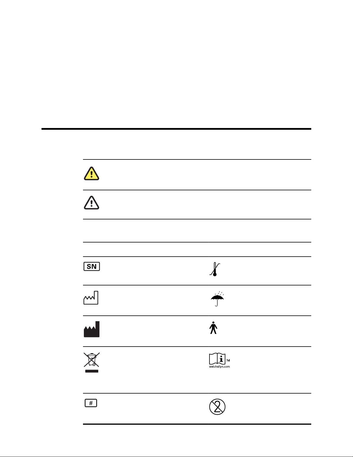
Symbols and indicators
Documentation symbols
WARNING The warning statements in this manual identify conditions or practices that could
lead to illness, injury, or death.
1
Regulatory symbols
Symbol
Caution The caution statements in this manual identify conditions or practices that could
result in damage to the equipment or other property, or loss of data. This definition applies to
both yellow and black and white symbols.
Description Symbol Description
Serial number Transport and storage
temperature range
Date of manufacture Keep dry
Manufacturer B Patient Applied Part According
to IEC60601-1
Return to Authorized
Representative, special disposal
required
Consult directions for use (DFU).
A copy of the DFU is available on
this website.
A printed copy of the DFU can be
ordered from Welch Allyn for
delivery within 7 calendar days.
Reorder number Single use, do not reuse
Page 6
2 Symbols and indicators Welch Allyn® OAE Hearing Screener
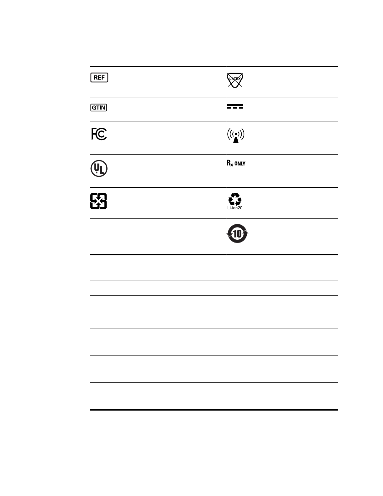
Symbol Description Symbol Description
2INRI9/66
Regulatory Product Identifier
(RPI) number
Global Trade Item Number Direct current (DC)
Federal Communications
Commission mark
UL Testing Services, Inc., with
respect to electri shock, fire, and
mechanical hazards only, in
accordance with UL 60601-1.
Recycle - Taiwan Recycle Lithium ion battery
Designates the battery type. 2 =
2 cells in series; I = Lithium ion;
N = Nickel; R = Cylinder; 19 =
19mm; 66 = 66mm
Not made with natural rubber
latex
Non-ionizing electromagnetic
radiation
For Use by or on the order of a
licensed medical professional
China RoHs
Indicator lights (LEDs)
Message
NOISE/Amber The indicator labeled ‘NOISE’ displays an amber light when the
TEST/Yellow The indicator labeled ‘TEST’ displays a yellow light when the
READY/Green The indicator labeled ‘READY’ displays a steady green light
CHARGE/Blue The indicator labeled ‘CHARGE’ displays a steady blue light
Definition
noise level measured during the test exceeds a nominal
threshold. It also is used to indicate some error conditions and
when the outcome of test is REFER, NOISY, or NO SEAL.
selected test is being performed. A steady yellow light
indicates that a test is in progress.
indicating that no test is being administer and that the screener
is ready to be used for testing.
when the battery is charging. The intensity of the blue light
indicates the progress of the battery charging.
Page 7

About warnings and cautions
Warning and caution statements can appear on the Welch Allyn OAE screener
(screener), on the packaging, on the shipping container, or in this directions for use.
The screener is safe for patients and clinicians when used in accordance with the
instructions and the warning and caution statements presented in this directions for use.
Before using the device, you must familiarize yourself with all warnings and cautions,
with the steps to power up the screener, and with the sections of this directions for use
that pertain to your use of the screener. In addition to reviewing the general warnings
and cautions presented in the next section, you must also review the more specific
warnings and cautions that appear throughout the manual in conjunction with setup/
startup, screener operation, patient monitoring, and maintenance tasks.
3
Warnings and cautions
WARNING Safety risk. Use only the provided power supply to charge the
screener. Injury to personnel or damage to the screener can result when a
three-prong to two-prong adaptor is connected between the screener
power supply and a mains outlet.
WARNING Safety risk. Only qualified Welch Allyn service representatives
should modify the screener. Improper modifications could be hazadous to
patients and personnel.
WARNING Safety risk. Any program aimed at obtaining reliable
measurements of otoacoustic emissions should be staffed and supervised
by appropriately trained individuals.
WARNING Electric shock hazard. This product should not be used in the
presence of fluid that can come into contact with any of the electronic
components or wiring. Should the user suspect fluids have contacted the
system components or accessories, the unit should not be used until
deemed safe by a Welch Allyn certified service technician.
WARNING Fire and explosion hazard. Do not use the screener in the
presence of flammable gaseous mixtures. There is the possibility of
explosions or fire when used in close proximity to flammable anesthetic
gases.
WARNING Fire and explosion hazard. Do not use the screener in a highly
oxygen-enriched environment, such as a hyperbaric chamber, oxygen tent,
and the like.
Page 8
4
About warnings and cautions Welch Allyn® OAE Hearing Screener
WARNING Electric shock hazard. Do not touch the contacts on the bottom
of the screener and the patient at the same time.
WARNING Safety hazard. This screener contains a rechargeable lithiumion battery. The battery is not user-replaceable and must be returned to an
authorized Welch Allyn service location for repair.
WARNING Fire and explosion hazard. Do not operate the screener in the
presence of a flammable anesthetic mixture with air, oxygen, or nitrous
oxide; in oxygen-enriched environments; or in any other potentially
explosive environment.
WARNING Safety risk. When handling and storing lithium-ion batteries,
avoid mechanical or electrical abuse. Batteries may explode or cause burns
if disassembled, crushed, or exposed to fire or high temperatures. Do not
short or install the battery with incorrect polarity.
WARNING Inaccurate measurement risk. Use only the disposable eartips
designed for use with the screener.
WARNING Patient injury risk. Never insert the probe tube into the ear
canal without a properly attached eartip.
WARNING Cross-contamination and nosocomial infection risk. The eartips
are disposable and for single patient use only. Do not clean and reuse
eartips.
CAUTION The screener has been verified by an independent laboratory to
conform to international standards for electromagnetic emissions and
immunity (EMC). The user is advised to avoid installation and use of this
screener in proximity to other products or equipment that may emit or be
susceptible to electromagnetic interference, including cellular phones. If
the screener is used adjacent to other products or equipment, you are
instructed to verify that no disturbance is found in the operation of this or
other equipment in proximity.
CAUTION The screener and its components will perform reliably only
when operated and maintained in accordance with the instructions
contained in this directions for use, accompanying labels, and inserts. A
defective product should not be used. Make sure all connections to
external accessories are tight and secured properly. Parts which may be
broken or missing or are visibly worn, distorted, or contaminated should be
replaced immediately with clean, genuine replacement parts manufactured
by or available from Welch Allyn.
CAUTION Equipment is not user repairable. Repairs and battery
replacement must be performed only by a qualified service representative.
CAUTION Use and store the screener indoors only. Operate the screener
within an ambient temperature range of 15°C / 59°F to 35°C / 95°F and in
relative humidity between 30% and 90% (non-condensing).
CAUTION Transport and store the screener in temperatures between
+5°C / 41° F to 40°C / 104° F.
CAUTION Annual calibration is recommended. Have an authorized Welch
Allyn service technician perform electrical safety checks on the unit in order
to maintain continued compliance with IEC and UL 60601-1.
Page 9

Directions for use About warnings and cautions 5
CAUTION Do not open the case of the screener. Only Welch Allyn service
personnel or an authorized repair center are authorized to perform warranty
service. Performing unauthorized service on a screener that is within
warranty may void the warranty.
CAUTION If the system is not functioning properly, do not operate it until
all necessary repairs are made. Test and calibrate the screener for proper
functionality in accordance with Welch Allyn published specifications
before using.
CAUTION Do not drop or otherwise cause undue impact to the screener.
If the screener is dropped or otherwise damaged, return it to Welch Allyn
for repair and calibration. Do not use the screener if any damage is
suspected.
CAUTION Recycle batteries whenever possible. In the United States call
1-800-8-BATTERY for information about recycling your lithium-ion battery or
go to the RBRC website at www.rbrc.org for additional information.
CAUTION For Use by or on the order of a licensed medical professional.
Page 10

6
About warnings and cautions Welch Allyn® OAE Hearing Screener
Page 11

Introduction
This directions for use describes the capabilities and operation of the Welch Allyn OAE
Screener.
The purpose of the screener is to provide rapid screening of Distortion Product
Otoacoustic Emissions (DPOAEs) or Transient Evoked Otoacoustic Emissions (TEOAEs)
at several frequencies.
7
Intended use
The Welch Allyn OAE Hearing Screener is a test instrument that measures otoacoustic
emissions in infants, children, and adults.
Indications for use
The Welch Allyn OAE Hearing Screener is indicated for testing of cochlear function in
infants, children, and adults by measuring otoacoustic emissions (OAEs). The OAEs are
generated by a series of clicks that are directed into the ear canal.
Otoacoustic emissions are low level audio-frequency sounds that are produced by the
cochlea as part of the normal-hearing process. Available evidence suggests that
otoacoustic emissions are generated by the cochlea’s outer hair cells and that the
presence of OAEs is an indication that the outer hair cells are viable. Clinical evidence
indicates that these emissions normally occur with normal hearing, or at most, mild
hearing loss (usually 30-40 dB HL). The majority of hearing-impaired individuals will be
identified by a simple OAE test.
Note Some product features described in this publication might not be available
in your country.
For information about any Welch Allyn product, contact Welch Allyn Technical Support:
www.welchallyn.com/about/company/locations.htm.
Page 12
Introduction Welch Allyn® OAE Hearing Screener
8
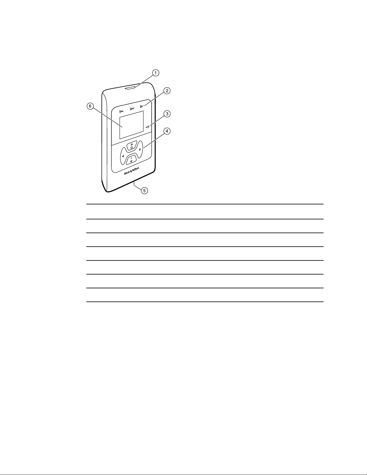
OAE functionality
Item number Description
1 Probe connector
2 Test status indicators
3 Charge status indicator
4 Control panel
5 Micro-USB Connector
6 Display
The system consists of the screener, probe, printer, single-use eartips, replaceable probe
tubes, and other accessories. The screener contains the hardware and software for
generating the test stimuli, measuring and displaying the OAEs, and storing the results
until they are printed. The plastic housing contains circuit boards that provide the signal
processing and display the test results.
The screener also contains a rechargeable lithium-ion battery. The screener displays the
test status using a liquid-crystal display (LCD) and three light-emitting diodes (LEDs). You
control testing, printing, and test protocol resets using four keypad push buttons.
The probe contains the speaker and microphone which produce test stimuli and measure
the sound pressure level (SPL) present in the sealed ear canal. Interface of the
instrument to the ear canal is accomplished through disposable eartips which fit onto the
probe tube. The disposable eartips are color coded by size for easy selection.
Page 13

Directions for use Introduction 9
Distortion product otoacoustic emissions
Distortion product otoacoustic emissions (DPOAEs) are acoustic signals that can be
detected in the ear canal of a person with normal outer hair cell function, subsequent to
stimulation of the auditory system with a pair of pure tones at frequencies f1 and f2. The
resulting emission of interest is the distortion product tone at the frequency 2f1-f2.
The screener generates a series of test tones, directs them into the ear canal, and then
measures the level of the DPOAE tone generated by the cochlea. By using different test
frequencies, the screener provides an estimate of outer hair cell function over a wide
range of frequencies.
Transient evoked otoacoustic emissions
Transient Evoked Otoacoustic Emissions (TEOAEs) are acoustic signals that can be
detected in the ear canal of a person with normal outer hair cell function, subsequent to
stimulation of the auditory system with a series of wideband clicks.
The screener generates a series of clicks, directs them into the ear canal, and then
analyzes the spectrum of the returning signal, separating the noise and emission. By
using band pass filters, the screener provides an estimate of outer hair cell function over
a wide range of frequencies.
Frequency Range tested
The frequency range tested is approximately 2 kHz to 5 kHz for DPOAEs. The frequency
range for TEOAEs is 1.5 kHz to 4 kHz.
Results storage and reporting
When the screener is set in its default settings, the instrument stores the results from
one patient (left and right ears) in its non-volatile memory for subsequent printing. The
screener is capable of storing up to 250 test results.
The results are displayed on the LCD on the front of the device and are stored in the
device’s internal memory. After testing is complete, results can be printed using the
printer or exported to a computer.
Sensitivity and specificity
Sensitivity and specificity in the screener are based on the test characteristics that you
define and may vary, depending on environmental and operating conditions. The
presence of otoacoustic emissions suggests normal outer hair cell function, which in
turn correlates to normal hearing. However, a passing result using the screener is not an
indication that the full auditory system is normal. Thus, a PASS result should not be
allowed to override other indications that hearing is not normal. A full audiologic
evaluation should be administered if concerns about hearing sensitivity persist. A REFER
test result should not be assumed to be an indicator of a lack of auditory function;
however, it should be followed with full audiologic diagnostic testing.
Page 14

10
Introduction Welch Allyn® OAE Hearing Screener
Page 15

Setup
Unpack the system
The following parts are shipped standard with each screener system:
Number of items Description
11
1 Welch Allyn OAE Screener Unit
1 Welch Allyn OAE Screener Probe
1 OAE Screener Cradle
1 Single Use Eartip Kit
1 Communications Cable, USB A/Micro-B
1 Communications Cable, USB A/B
1 Charging Cable, PSU 5V/Micro-B
1 Calibration Certificate
1 OAE Hearing Screen software CD includes: Quick Start Guide, Data Manager
software DFU, and Data Manager software
If any part is missing, contact Welch Allyn Technical Support: www.welchallyn.com/
about/company/locations.htm. We recommend that you save the shipping box and
packing materials in case you need to store or ship the system.
Page 16
12
Setup Welch Allyn® OAE Hearing Screener
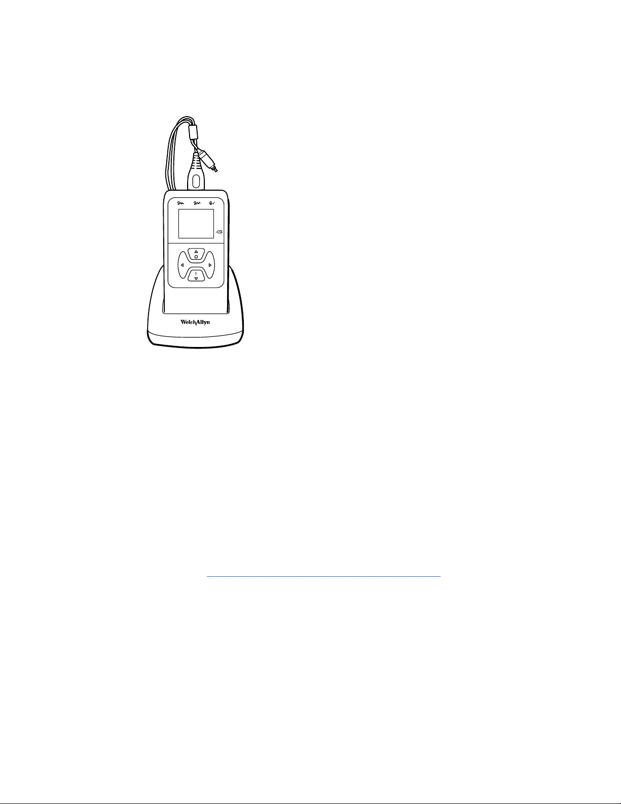
Cradle
You can place the screener in the cradle to charge the device or to connect to a
computer for communication with the Welch Allyn Data Manager (data manager). You
can also charge the device or connect to a computer directly from the screener. The
remainder of this directions for use assumes that you are charging the device or
communicating with a computer from the screener.
Charge the battery
The screener is powered by an integrated, rechargeable lithium-ion battery providing 15
hours of operation between full charging. The battery status is indicated by the battery
icon shown in the upper right corner of the Main Menu. Full battery charge is
represented by a full battery symbol on the display and reduces to an empty battery in
increments corresponding to the discharge of the battery.
Note Misalignment of the Micro-USB plug and socket can cause damage. The
plug and socket should be visually inspected prior to each installation of the
charging cable. If you see damage, contact Welch Allyn Technical Support:
www.welchallyn.com/about/company/locations.htm.
Battery status indicator
A blue battery status indicator light, located to the right of the screen, lights up when the
battery is charging and indicates the charging progress
The indicator light appears whenever the Micro-USB connector is engaged and powered.
The illumination behavior identifies the status of the charging function, and is defined as
follows:
• Steady: the battery is fully charged. This identifies that the charging cycle is
complete. If the indicator is steady when you plug in the screener, the battery is fully
charged.
• Slow blink: the battery is charging.
Page 17

Directions for use Setup 13
• Fast blink: a fault condition. Return the screener to Welch Allyn for service or repair.
For information about returning any device to Welch Allyn, see "Repairs" and
"Returning products."
When you use the screener, you are warned that the battery charge is low by two fast
blinks followed by a pause and then two fast blinks. This sequence is repeated until you
place the battery in the charge mode.
Charge the battery using the USB port
The screener is powered by an integrated, rechargeable lithium-ion battery providing 15
hours of operation between full charging. The battery status is indicated by the battery
icon shown in the upper right corner of the Main menu. A lighted battery icon indicates a
fully charged battery. The battery icon segments turn off as the battery charge
decreases.
1. Insert the Micro-USB plug into the Micro-USB port on the bottom of the screener
2. Insert the wall charger into the mains outlet.
Charge the battery using the cradle
Note The Micro-USB port on the cradle does not support data transfer.
1. Insert the Micro-USB plug into the Micro-USB port on the back of the cradle.
2. Insert the wall charger into the mains outlet.
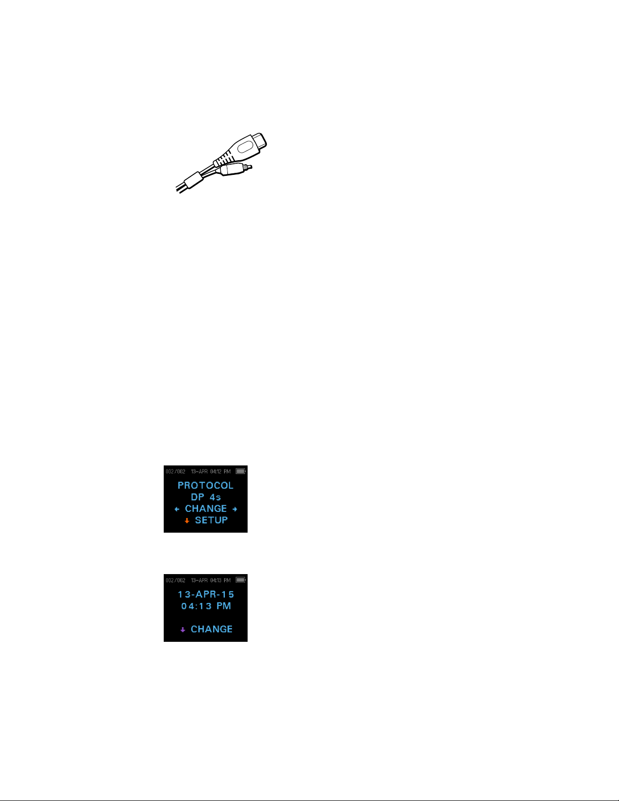
Install the probe
Insert the probe’s HDMI connector firmly into the socket on the top of the screener.
The plug fits only in one direction.
CAUTION Misalignment of the HDMI connector and socket
can cause damage. The plug and socket should be visually
inspected prior to each installation of the probe. If you see
damage, contact Welch Allyn Technical Support:
www.welchallyn.com/about/company/locations.htm.
Page 18
14
Setup Welch Allyn® OAE Hearing Screener
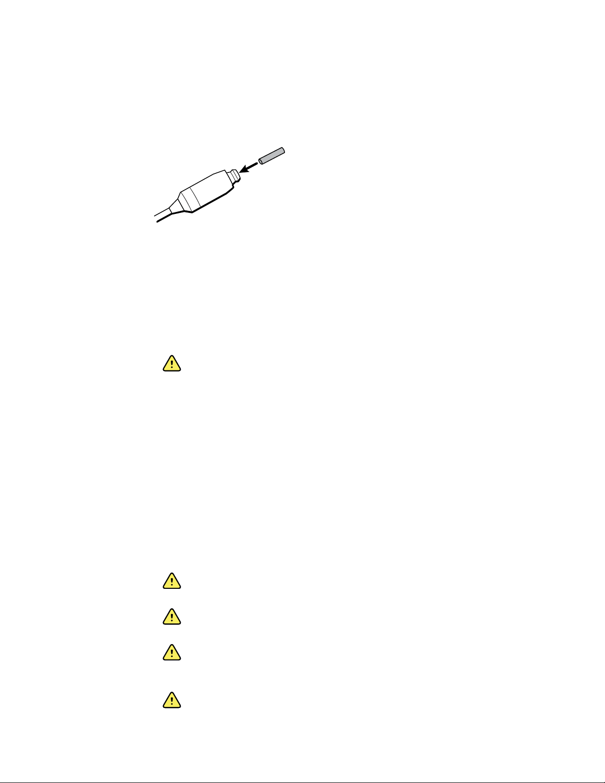
Attach the probe tube
A clear probe tube must be attached to the probe head before an eartip is applied.
1. Insert a new probe tube into the probe head until it is fully seated.
A properly inserted probe tube snaps securely into place when it is fully seated in the
probe head.
2. To remove a probe tube, grasp the tube and pull gently away from the probe head
with a slight twist.
It is not necessary to replace the probe tube with each eartip; the tube is reusable as
long as the probe tube is clear.
WARNING If the probe tube becomes dirty or clogged, it must be
replaced. A dirty probe tube may produce wrong results.
Eartips
The screener comes with a box of disposable, single-use eartips that fit a variety of ear
canal sizes. The determination of the appropriate eartip size should be made by persons
with proper training and experience. The probe must have a probe tube applied and an
eartip attached before inserting it into an ear canal. The eartip must seal the ear canal.
The best test results are obtained when the eartip is inserted deeply into the ear canal
instead of flush with the ear canal opening. Caution must be taken, however, to ensure
that the eartip does not extend too deeply into the ear canal. Use only the eartips
approved for use with the instrument. The eartips are disposable and must be replaced
after each patient.
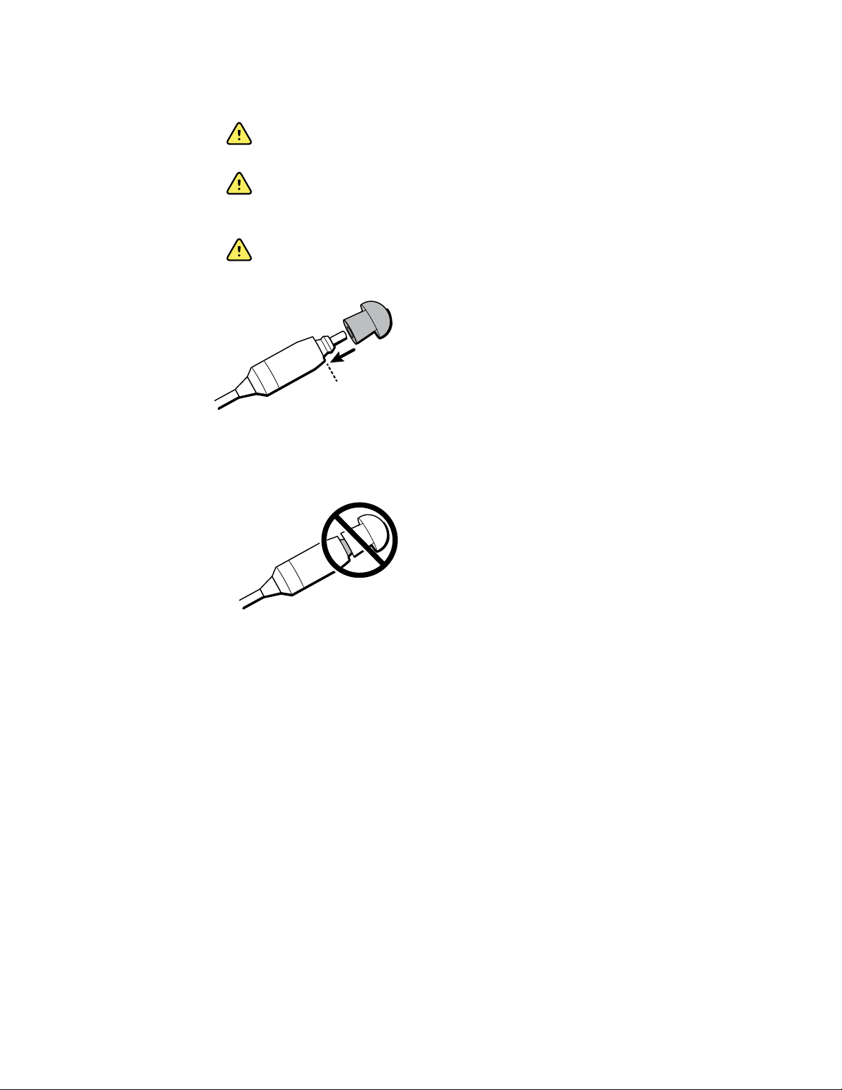
Attach and remove the eartips
WARNING A clear probe tube must be applied to the probe head before
an eartip is applied.
WARNING The eartips are disposable and must be replaced after each
patient. Failure to do so may cause infection.
WARNING The screener probe must have a probe tube and an eartip
attached before inserting the screener probe into the ear canal. Failure to
do so may cause infection.
WARNING A person with proper training and experience must determine
the appropriate eartip size. Failure to do so may cause infection.
Page 19
Directions for use Setup 15
WARNING Ensure that the eartip does not extend too deeply into the ear
canal. Failure to do so may cause infection.
WARNING If the probe tube becomes dirty or clogged, it must be
replaced. Failure to do so may cause injury to the ear canal or wrong results
or both.
WARNING Use only the eartips approved for use with the screener.
Failure to do so may cause injury to the ear canal.
1. Select the appropriate-sized eartip.
2. Push and slightly twist the eartip onto the probe tube.
Ensure that the eartip is fully seated on the probe. There should be no gaps between
the eartip and the collar of the probe head.
3. To remove the eartip, grasp the probe tube gently at the base and slightly twist it
while pulling the eartip off of the probe tube.
Grasping the base of the probe tube will prevent it from being inadvertently pulled
out of the probe head along with the eartip.
Probe holder
The probe holder is a receptacle attached to the HDMI cable that secures the probe
when you are not using the screener. Placing the probe into the probe holder protects
the probe head. Welch Allyn recommends that you insert the probe into the probe holder
when the screener is not in use, such as when it is on a counter top or table, or when
the screener is placed in the screener cradle.
Page 20
16
Setup Welch Allyn® OAE Hearing Screener
Attach the probe holder
1. Place the probe holder near the end of the probe cable at the HDMI connector end.
2. Gently press the probe cable into the probe holder close to the point of the probe
head.
Clock settings
Set the date and time before using the screener. The clock should be set prior to testing
because changing the date and time after tests are saved will not change the date on the
printout.
Seasonal time changes, such as Daylight Saving Time, also require resetting the clock.
Note If the screener is being powered on for the first time or if the battery is
completely discharged and is not charged within approximately one hour,
an Error! Reference source not found may appear. If this message
appears, reset the date and time.
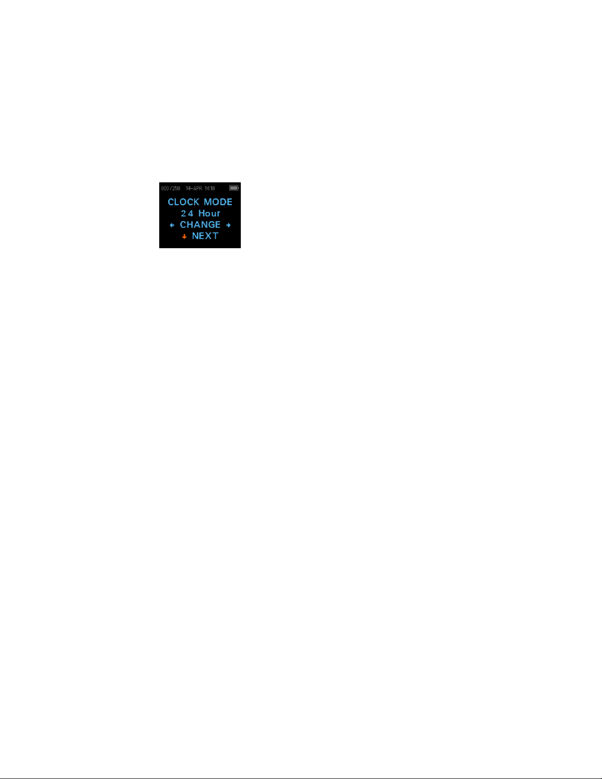
Access the clock menu
1. While viewing the MAIN menu, press the DOWN control panel button.
The PROTOCOL menu appears.
2. While viewing the PROTOCOL menu, press the DOWN control panel button.
The clock menu appears with the current date and time.
Page 21
Directions for use Setup 17
Change the clock mode
The Clock Mode menu enables you to change the clock from a 24 hour mode to a 12
hour mode.
1. See "Access menus" for how to access menus.
2. On the control panel, press the DOWN button to advance to the CLOCK MODE
menu.
3. Press either the LEFT or RIGHT control panel button to change from the 12 to 24
hour mode or from the 24 to 12 hour mode.
4. Press the UP control panel button repeatedly to return to the MAIN menu.
Change the date and time
1. If the date and time are correct, press the UP control panel button to return to the
main menu. If either the date or time are not correct, go to Step 2.
2. If the month is incorrect, from the Main menu press the DOWN control panel button
three (3) times to advance to the Month menu.
3. Press the LEFT or RIGHT control panel button to advance to the correct month.
4. Press the DOWN control panel button to advance to the Day menu
5. Press the LEFT or RIGHT control panel button to advance to the correct day.
6. Continue Steps 4–5 to correct the year, hour, and minute settings.
7. When the year and hour settings are correct, press the UP control panel button
repeatedly to return to the Main menu.
8. If you are at the Minute menu, press the DOWN control panel button to return to the
Main menu.
Page 22

18
Setup Welch Allyn® OAE Hearing Screener
Page 23

Device overview
Control panel
19
The screener uses four (4) buttons to control all functions. The arrows on the keypad
(LEFT, RIGHT, UP, and DOWN) correspond to the arrows on the screen. Push the button
that corresponds to the highlighted arrow on the screen in order to move through tasks.
Note The UP key always brings the screener back to either the previous menu or
Access menus
1. While viewing the MAIN menu, press the down control panel button on the control
panel.
The PROTOCOL menu appears. DPOAE screeners will show DP 4s in the MAIN
menu. TEOAE screeners will show TE 64s in the MAIN menu.
2. While viewing the PROTOCOL menu, press the down control panel button on the
control panel.
The Clock menu appears with the current date and time.
3. While viewing the CLOCK menu, press the down control panel button on the control
panel until the green LED READY light on the screener turns off.
the main menu. The UP key will also access the print command from the
Main menu.
4. Release the down control panel button.
Page 24

Device overview Welch Allyn® OAE Hearing Screener
20
When you release the down button, the WIRELESS DEVICE screen appears and the
menus are accessible.
5. Press the down control panel button to advance to other device settings.
Device settings
The screener menus enable you to change many of the screener settings or functions.
These settings include:
• Wireless device pairing
• Clear test results
• Automatic shutdown interval
• Save mode
• Minimum amplitude value
• Clock Mode
• Graph style
• Normative Data for DPOAE
• Language
• Reset to default settings
Wireless device pairing
The wireless pairing menu enables you to pair the screener with a wireless device, such
as a thermal printer or computer, for printing test results and data transfer. However, you
can only pair one device with the screener at any given time.
Pair the screener and wireless device
Note When pairing to a computer for use with the data manager, confirm the
computer has wireless availability or a wireless dongle will be required.
Confirm the wireless settings of the computer by selecting ‘Allow wireless
devices to find this PC‘.
1. Turn on the device to be paired with the screener.
2. On the screener, navigate to the WIRELESS DEVICE menu.
3. Press the LEFT or RIGHT control panel button to initiate discovery of available
wireless devices.
The screener searches for available wireless devices for approximately 15 seconds.
During this time the message "Please Wait" appears on the screen. The yellow LED
l
ight flashes.
4. When the correct computer appears on the screen, press the DOWN control panel
button to pair the screener and computer.
Page 25

Directions for use Device overview 21
The message "Add a device" appears on the computer.
5. Select this notice, and then enter PIN 1234.
6. The first time the data manager software is launched, select Detect Com Port to
finalize the screener and computer connection.
7. To cancel the pairing process, press the CANCEL control panel button.
The screener returns to the Main menu.
Select a wireless device
When discovery is complete, all discovered devices appear in the order in which they are
found. A compatible thermal printer appears as “ PRT-##-##” (for example, PRT-0a-de).
Other devices appear by their name. These name configurations vary depending on the
device.
1. See "Access menus" for how to access menus.
2. On the WIRELESS DEVICE menu, press either the LEFT or RIGHT control panel
button to select the desired device.
3. Press the PAIR control panel button to pair the screener with the selected device.
The screen confirms pairing with the message “WIRELESS DEVICE PAIRED” .
4. Press the MainMenu control panel button to exit the wireless pairing menu.
5. See “Troubleshooting” in the Maintenance section if wireless pairing is unsuccessful
or if any error messages appear.
Clear test results
The Test Results menu enables you to clear the test results stored in the screener
without printing them.
1. See "Access menus" for how to access menus.
2. Press the DOWN control panel button to advance to the TEST RESULTS menu.
3. Press the LEFT or RIGHT control panel button to clear the results.
4. Press the LEFT or RIGHT control panel button to select Yes or No to clear the
results.
5. Press the NEXT control panel button to advance to the next screen without clearing
the results.
After printing results or transferring data to your computer, all tests saved in memory
are marked for deletion and are permanently deleted when a new test is started. It is
not necessary to manually clear these results.
6. Press the UP control panel button repeatedly to return to the MAIN menu.
Page 26

Device overview Welch Allyn® OAE Hearing Screener
22
Minimum amplitude
The Minimum Amplitude setting enables you to set the screening device to include
minimum amplitude values in the PASS/REFER criterion. The minimum Distortion
Product (DP) OAE amplitude is –5 dB SPL. The minimum Transient Evoked (TE) OAE
amplitude selections are –5 dB or –10 dB SPL. If the MIN VALUE is set to ON, a result is
not considered a pass unless the amplitude at each frequency is equal to or greater than
the minimum value programmed into the screener. This is in addition to meeting the
other pass criteria including the minimum SNR and the number of passing frequencies
for an overall test PASS.
This feature is set to OFF when it is shipped from the factory.
Change the language
The LANGUAGE menu enables you to select the language used in the screener.
1. See "Access menus" for how to access menus.
2. Press the DOWN control panel button to advance to the LANGUAGE menu.
3. Press either the LEFT or RIGHT control panel button to scroll to the desired
anguage.
4. Press the UP control panel button repeatedly to return to the MAIN menu.
Reset to default
The RESET TO DEFAULT menu returns all screener settings to its original factory
defaults.
Reset to default settings
1. See "Access menus" for how to access menus.
2. Press the DOWN control panel button and advance to the RESET TO DEFAULT
menu.
3. Press the LEFT or RIGHT control panel button.
4. Press the LEFT or RIGHT control panel button to select Yes or No to verify the reset
or cancel your request.
Resetting to the factory default settings disconnects any wireless device, clears the
test results, and resets all system settings.
5. Press the UP control panel button to return to the Main menu.
Page 27

Operating instructions
Turn on the screener
Press the DOWN control panel button located below the display screen.
A yellow TEST light appears briefly above the display. The green READY light
remains constant, indicating that the screener is ready to use. A Flash Screen
appears briefly, displaying the software version, serial number, calibration date, and
type of instrument, such as SCR Screener with DP or TE.
23
Automatic shutdown interval
The screener has an automatic shutdown feature designed to prolong battery life. The
screener automatically shuts down after one (1) minute of inactivity, but the interval can
be adjusted.
The interval choices are:
• 30 seconds
• 1 minute
• 2 minutes
• 4 minutes
See “Change the automatic shutdown interval” for directions on how to select a
different interval.
Note To power on the screener, from the MAIN menu, press the DOWN control
panel button. To power off the screener manually, from the MAIN menu,
press the UP control panel button.
Change the automatic shutdown interval
The POWER OFF menu enables you to change the automatic shutdown interval.
1. See "Access menus" for how to access menus.
2. Press the DOWN control panel button to advance to the POWER OFF menu.
Page 28

24
Operating instructions Welch Allyn® OAE Hearing Screener
3. Press either the LEFT or RIGHT control panel button to change to the desired
interval.
4. Press the UP control panel button repeatedly to return to the MAIN menu.
Main menu
The main menu has seven regions. The following screen and table define these regions.
Number Item Definition
1 Number of stored tests Displays the number of saved tests over the maximum possible tests
2 Date and time The day/month, time, and AM/PM
3 Battery status Displays the amount of charge remaining or the charging status
when plugged into a mains outlet with the Micro-USB cable
4 Selected protocol Displays protocol options: DP 4s (default) and DP 2s on DPOAE
screeners, TE 64s (default) or TE 32s on TEOAE screeners
5 Start right ear test Press to start a right ear test
6 Change protocol and settings Press to change a protocol or screener settings (see Instrument
Settings for more information)
7 Start left ear test Press to start a left ear test
Page 29

Directions for use Operating instructions 25
Select the test protocol
The DPOAE screener provides two (2) protocol options: DP 4s testing at a maximum
time of 4 seconds per frequency and DP 2s testing at a maximum time of 2 seconds per
frequency. The TEOAE screener provides two (2) protocol options: TE 64s testing a
maximum time of 64 seconds and TE 32s testing a maximum 32 seconds. The last
protocol used appears on the Main menu.
1. Press the LEFT or RIGHT control panel button on the Main menu.
The Change Protocol menu appears.
2. Press the LEFT or RIGHT control panel button to select the desired protocol.
3. Press the UP control panel button repeatedly to return to the Main menu and begin
testing.
4. Press the Down control panel button to access the device menus.
See “Appendix E: Configurations and test protocols” for further information on protocol
settings.
Prepare the patient for testing
Otoscopic examination of the patient’s ear canals is recommended prior to testing.
Excessive cerumen or vernix in the ear canals may interfere with the test and give invalid
or incomplete results. Patients with excessive cerumen, vernix, debris, or foreign bodies
in the ear canals should be referred to a physician or other qualified health care
professional for removal of the blockage prior to testing.
1. Place the patient in a position that will allow easy access to the ear canal.
2. Instruct the patient to remain quiet and still during the test.
Start a test
1. Gently pull up and back on the outer ear during eartip insertion to straighten the ear
2. Gently insert the eartip into the ear canal. It should fit snuggly and comfortably.
3. Press either the LEFT or RIGHT control panel button for the TEST menu to select
4. Repeat steps 1–3 to test the opposite ear.
canal and ensure proper placement and seal.
Note The best test results are obtained when an eartip is inserted
into the ear canal instead of flush with the ear canal.
which ear is tested.
After the ear to be tested is selected, the AutoStart Probe Check begins
automatically.
AutoStart probe check
The Probe Check display shows a cone, larger at the left and tapering toward the right,
representing the ear canal volume—from left to right—from very large (blue area) to very
small (orange area).
Where the vertical white bar appears indicates the measured ear canal volume:
Page 30

Operating instructions Welch Allyn® OAE Hearing Screener
26
Ear canal volume Explanation
Blue The ear canal volume is too large for the test to begin. The probe is not in the ear or
there is a large leak.
Green The ear canal volume is in the target range for testing. The test will begin automatically
if the probe fit is stable.
Orange The ear canal volume is too small for the test begin. The eartip may be pressed against
the ear canal wall or the probe tube may be completely clogged.
Gray Ear seal indicator remains gray until a seal is obtained.
Troubleshoot the AutoStart probe check
Appropriate adjustments of the eartip position and size selection should be made until
the indicator falls within the green area and remains stable. If the test will not progress
past the AutoStart probe check stage:
1. Change the probe tube.
2. Confirm that the probe connector is fully seated in the socket.
3. Run the AutoStart probe check again.
Page 31

Test results
Test phase
The screener automatically performs a calibration at the start of each test. During
calibration a series of tones are sent to the ear canal to calibrate the levels of the
frequencies to be tested. Following calibration of the test tones, the test phase begins
automatically.
27
Note Press the UP control panel button to abort a test in progress. No record of
Graph styles
The results of a test are displayed as a graph. The graph is generated and shown during
the test and can be viewed after the test is complete.
There are two graph options for viewing the results:
• The default view is a signal-to-ratio (SNR) bar graph. It displays the SNR for each DP
test frequency or TE frequency band.
• The value graph view displays the absolute emission and noise levels for each DP
test frequency or TE frequency band.
SNR bar graph view
The default SNR bar graph view displays the emissions and noise floor (NF) as they are
measured. Each column represents one DP test frequency or one TE frequency band.
The height of each column represents the SNR being measured.
an aborted test is saved in memory.
The horizontal green line at the decibel level corresponding to the SNR indicates the level
required for a PASS. A green bar indicates a PASS and a yellow bar indicates a REFER.
See “Change graph style” for instructions on how to switch the graph views between
SNR bar graph and value graph.
Page 32

Test results Welch Allyn® OAE Hearing Screener
28
Value graph view
The value graph view uses different colors and symbols to differentiate the DP test
frequency or TE frequency band for the left and right ear tests:
• Left ear: Dark blue line with “x” symbols indicate the DP test frequencies or TE
frequency bands.
• Right ear: Red line with circles indicate the DP test frequencies or TE frequency
bands.
On both the left and right ear value graphs, inverted triangles on a light blue line
represent the NF at each DP test frequency or TE frequency band.
See “Change graph style” for instructions on how to switch the graph views between
SNR bar graph and value graph.
Change graph style
The Graph menu enables you to change between the SNR and value graph views.
1. See "Access menus" for how to access menus.
2. Press the DOWN control panel button to access the GRAPH menu.
3. Press the LEFT or RIGHT control panel button to change between the SNR and
value graph views.
Normative data display
The Norms setting allows the user to display the Expanded Boys Town Norms template
on the Value Graph for eligible DPOAE protocols. The normative data does not affect the
PASS/REFER criteria or the results of the DP screening test. Norms are for viewing
purposes only.
1
The values used to create the template are shown in Table A1 from Gorga, M.P., Neely, S.T., Ohlrich,
B., Hoover, B., Redner, J. and Peters, J. (1997). “From laboratory to clinic: a large scale study of
distortion product otoacoustic emissions in ears with normal hearing and ears with hearing loss.” Ear &
Hearing, 18, 440-455.
1
Page 33

Directions for use Test results 29
Test techniques
As with other OAE test instruments, there are techniques to learn when using the
screener, especially when screening infants. Experience with existing OAE systems
suggests that it may take up to three (3) months to become completely proficient in
screening infants.
Test an infant
Note The best test results are obtained when an eartip is inserted into the ear
canal instead of flush with the ear canal.
When testing an infant with the screener, the infant has to be relatively quiet and calm; it
is preferable that the infant be sleeping. If the infant is awake:
1. Use a pacifier to calm the infant; however, sucking adds noise to the test and
decreases the likelihood of a PASS result.
2. Press either the LEFT or RIGHT control panel button to select which ear is tested.
3. Pull gently down and back on the pinna to straighten the ear canal.
4. Gently insert the eartip into the ear canal. It should fit snuggly and comfortably.
5. Repeat steps 2–4 to test the opposite ear.
Test children with pressure equalizer tubes
Disable the AutoStart probe check when testing children with pressure equalizer (PE)
tubes.
1. Pull gently up and back on the outer ear to straighten the ear canal.
2. Insert the probe with the appropriate eartip into the ear canal and obtain a proper
seal.
3. Press and hold the arrow key that corresponds to the ear being tested until the
green READY light turns off.
4. Release the arrow key.
The screener calibrates and tests as before, applying the appropriate in-the-ear
stimulus intensity levels for patients with PE tubes.
5. Repeat steps 1-4 to test the opposite ear.
Noise sources
When the noise level exceeds the noise rejection limit of the screener, the red NOISE
light appears. It is common for the red NOISE light to appear while testing. The light
appears infrequently if the noise level in the ear canal is low, and it appear more
frequently if the noise level in the ear canal is high.
For TEOAE screening protocols (TE 64s, TE 32s), the test will pause when noise levels
exceed the noise rejection limit. Pause is indicated when the Noise, Test and Ready
lights turn on simultaneously. Testing will automatically resume when noise levels
decrease. Total pause time will not exceed 30 seconds.
OAEs are very low-level sounds. Any noise in the ear canal at the time of testing can
mask this emission. This noise can come from a variety of sources.
Page 34

Test results Welch Allyn® OAE Hearing Screener
30
The largest source of noise usually comes from the patient. This is biological noise, such
as movement, coughing, sucking, talking, and the like. The patient must be calm and not
move or talk. Ambient noise in the testing environment also can be a large source of
noise during the test. A properly sealed eartip blocks much of this noise but performing
the testing in a relatively quiet environment is recommended.
View results
When testing is complete, the green “READY” light is illuminated and the results for the
ear tested appear. The results screen indicates the test ear and gives the results of the
test.
The results are automatically saved in memory as soon as the test completes. The
results are saved even if the screener is turned off or the battery is depleted.
Note When the screener is operating in the Save L/R Mode, the screener saves
only the last test for each ear. Starting a new test for the same ear
overwrites the existing test.
The following screens represent the possible test results:
• PASS: The ear tested passed screening.
• REFER: The ear tested did not pass screening.
• NOISY: Excessive noise was present during the test.
• NO SEAL: A seal was not maintained throughout the test.
• FIT ERR: Inadequate probe placement in the ear canal to produce target stimulus
intensities.
See “Manage test results” for more information on managing results and how to print or
transfer those results to the Welch Allyn Data Manager.
See “Save results” for more information on the screener save mode options.
Repeat an inconclusive test
A conclusive test has a PASS or REFER result. Repeat the test if the test result is
NOISY, NO SEAL, or FIT ERR.
1. Reposition the probe, selecting a different size eartip if necessary.
2. Follow the directions that begin in “Select a protocol” to retest the patient.
3. To review the results, press the DOWN control panel button to return to the bar
graph.
4. After reviewing the results, press the DOWN control panel button to return to the
Results screen or the UP control panel button to return to the Main menu.
Page 35

Manage results
Results storage and reporting
When the screener is set in its default settings, the instrument stores the results from
one patient (left and right ears) in its non-volatile memory for subsequent printing. The
screener is capable of storing up to 250 test results.
The results are displayed on the LCD on the front of the device and are stored in the
device’s internal memory. After testing is complete, results can be printed using the
printer or exported to a computer.
31
Save/Store test results mode
The screener automatically saves the results of completed tests in the non-volatile
memory even if the battery is temporarily discharged. However, the screener is not
intended for long-term storage of test results.
Note You are strongly encouraged to print or transfer all test results at the
completion of testing to avoid potential loss of data.
The screener has two operating modes for saving and storing test results:
• SAVE L/R
• SAVE 250
SAVE/LR is the default operating mode.
SAVE L/R mode
When operating in the default SAVE L/R mode, the screener saves the most recent test
results for each ear and prints or transfers only these results. This allows you to retest a
patient after a REFER result and to print or transfer only the most recent test result for
each ear.
Welch Allyn recommends that you print the results after each patient when using the
default mode.
SAVE 250 mode
When operating in the SAVE 250 mode, the screener can save up to 250 tests. There are
two methods of using the SAVE 250 mode:
Page 36

Manage results Welch Allyn® OAE Hearing Screener
32
• When not used with the Welch Allyn Data Manager (data manager), the screener
automatically numbers each test from 1 to 250. When using the SAVE 250 test
mode for numbered tests, keep a record of the test number for each patient in order
to synchronize the numbered test with the correct patient.
• When used with the data manager, the data manager transfers patient names to the
screener and the screener displays the names.
When not used with the data manager, each test is automatically incremented, starting
with test number 001.
When the screener is used with the data manager, the patient names are displayed on
the screener in alphabetical order. See “View patient names” for directions on how to
scroll between patient names.
When the screener reaches 245 saved tests, you are warned that the memory is almost
full. When the screener reaches 250 saved tests, the memory is full and no further tests
can be done. Do one of the following:
• Print the results,
• Transfer the results to the PC software
• Clear the results from memory.
Change the SAVE mode between SAVE L/R and SAVE 250
Before changing the SAVE mode, print all tests stored in memory.
1. See "Access menus" for how to access menus.
2. Press the DOWN control panel button to advance to the SAVE L/R screen.
3. Press the LEFT OR RIGHT control panel button to change between the SAVE L/R
(single) setting and SAVE 250 (multiple) setting.
4. Press the UP control panel button repeatedly to return to the MAIN menu.
View patient names
When patient names are uploaded from the data manager to the screener, the patient
names are displayed on the screener in alphabetical order. The first name shown is
labeled "Unnamed" to allow tests to be conducted on patients whose names have not
been transferred.
To move to a different patient name than the one displayed on the screener, press
the LEFT or RIGHT control panel button to advance through the names until the
desired patient name appears.
Page 37

Directions for use Manage results 33
Delete test results
The screener holds data in non-volatile memory. The data stays in the memory even
after data is printed on the thermal printer or downloaded to the data manager. The save
mode determines how data is deleted.
Delete results in SAVE L/R mode
The most recent test for the left ear and the most recent test for the right ear are held in
memory. Data is deleted when a new test for the left or right ear is completed.
1. See "Access menus" for how to access menus.
2. Press the DOWN control panel button to advance to the X TEST RESULTS menu. "X"
represents the number of tests held in memory in the screener.
3. Press the LEFT or RIGHT control panel button.
4. Press the LEFT or RIGHT control panel button, and then press the appropriate LEFT
or RIGHT control panel button to select YES or NO to verify or cancel your choice.
If you select YES, the data is cleared from the screener. After printing results or
transferring data to your PC software, all tests saved in memory are marked for
deletion and are permanently deleted when a new test is started. It is not necessary
to manually clear these results.
Delete results in SAVE 250 mode
Data is deleted when new Patient Names are uploaded from the data manager to the
screener. A warning is provided that data will be deleted. Data can be deleted in the
screener from the data manager when the screener is connected to the data manager by
the USB cable or by wireless. When Names is selected, the window allows data to be
deleted using the Clear Instrument button.
To delete data using the TEST RESULTS menu:
1. See "Access menus" for how to access menus.
2. Press the DOWN control panel button to advance to the TEST RESULTS screen.
3. Press the LEFT or RIGHT control panel button.
4. Press the LEFT or RIGHT control panel button, and then press the appropriate LEFT
or RIGHT control panel button to select YES or NO to verify or cancel your choice.
If you select YES, the data is cleared from the screener. After printing results or
transferring data to your PC software, all tests saved in memory are marked for
deletion and are permanently deleted when a new test is started. It is not necessary
to manually clear these results.
Connect the screener to a computer
1. Power on the screener and ensure that the screener is charged.
2. Plug the micro-USB connector into the port on the bottom of the screener.
3. Plug the USB connector into a USB port on the computer.
4. Power on the computer, and then launch the data manager.
The message, “Waiting On PC” appears on the screener.
Page 38

34
Manage results Welch Allyn® OAE Hearing Screener
5. Begin data or name transfers.
Connect the screener cradle to a computer
Use a standard USB-A to USB-B cable to connect the screener cradle to a computer.
1. Power on the screener and ensure that the screener is charged.
2. Plug the USB-B connector into the port on the back of the screener cradle.
The cradle does not need to be connected to a mains outlet for data transfer.
3. Plug the USB-A connector into a USB port on the computer.
4. Place the screener in the cradle.
5. Power on the computer, and then launch the data manager.
The message, “Waiting On PC” appears on the screener.
6. Begin data or name transfers.
You must use a USB-A to USB-B cable between the cradle and the computer for data
transfer. The micro-USB port on the cradle does not support data transfer. Use the cradle
for recharging the screener when power is supplied to the either the micro-USB or the
USB-B port. Use the micro-USB port on the bottom of the screener for both data transfer
and recharging.
Connect the screener to a computer using wireless
1. Welch Allyn OAE ScreenerDFU1.0Power on the screener and ensure that the
screener is charged.
2. Power on the computer, and then launch the data manager.
The message, “Waiting On PC” appears on the screener.
3. If this is the first time the screener is being connected using wireless, then on the
Transfer section of the Home tab, click Detect Com Port.
4. Ensure that the screener is paired to your computer.
Pairing is only required upon initial data transfer.
5. On the Main menu of the screener, press the UP control panel button.
The wireless menu appears.
6. Press the LEFT or RIGHT control panel button to begin data or name transfers.
Pair the screener and wireless device
Note When pairing to a computer for use with the data manager, confirm the
computer has wireless availability or a dongle will be required. Confirm that
the computer is discoverable and that wireless devices can pair with it.
1. Turn on the device to be paired with the screener.
2. On the screener, navigate to the New Wireless Device menu.
3. Press the LEFT or RIGHT control panel button to initiate discovery of available
wireless devices.
The screener searches for available wireless devices for approximately 15 seconds.
During this time the message "Please Wait" appears on the screen. The yellow LED
light flashes.
Page 39

Directions for use Manage results 35
4. When the correct computer appears on the screen, press the DOWN control panel
button to pair the screener and computer.
The message "Add a device" appears on the computer.
5. Select this notice, and then enter PIN 1234.
6. The first time the data manager software is launched, select Detect Com Port to
finalize the screener and computer connection.
7. To cancel the pairing process, press the CANCEL control panel button.
The screener returns to the Main menu.
Print to a thermal printer
You must have an optional wireless thermal printer to print from the screener. See “Pair
the screener and wireless device” for directions. You can only pair one device with the
screener at any given time.
1. Confirm that the printer is on and ready for printing.
2. Confirm that the screener is paired with the printer.
3. From the main menu, press the UP control panel button.
The CONNECT TO PRT screen appears.
4. Press the LEFT or RIGHT control panel button to connect to the printer.
The screener searches for the paired printer; when the screener pairs with the
printer, all stored results print. All printed test results are marked for deletion, but are
stored in memory until a new test is started. This enables you to reprint the tests if
printing was unsuccessful due to the paper running out or other issue. This also
allows you to transfer test data to the data manager for long term storage before you
start a new test. When a new test is started, all tests in the screener memory are
erased. The screener turns off automatically when printing is complete.
Page 40

36
Manage results Welch Allyn® OAE Hearing Screener
Page 41

Understand printed results
DPOAE printout
The following information is provided for each test:
• The time and date of the test, based on the setting of the internal clock; if the clock
is set correctly, this time and date will be correct
• The test number (if operating in SAVE 250 mode)
• The protocol selected (for example, DP 2s)
• The averaging time used for this test (for example, 2 sec avg)
• Instrument and probe serial number (SN)
• The software version number (for example, V104.04)
• The ear selected (Right or Left)
• A PASS/REFER indication
• The f2 frequency in kHz (for example, 2.0, 3,0, 4.0, 5.0)
• The noise floor (NF) in dB SPL
• The emission level (DP) in dB SPL
• The signal-to-noise ratio (SNR)—DP level minus the NF—in dB
• The Value or SNR graph as selected on the screener
• "MIN*" if the Minimum Amplitude setting was enabled
37
TEOAE printout
The following information is provided for each test:
• The time and date of the test, based on the setting of the internal clock; if the clock
is set correctly, this time and date will be correct
• The test number (if operating in SAVE 250 mode)
• The protocol selected (for example, TE 64s)
• The averaging time used for this test (for example, 12 sec avg)
• Instrument and probe serial number (SN)
• The software version number (for example, V104.04)
• The ear selected (Right or Left)
• A PASS/REFER indication if there is a criterion set for the selected protocol
• The frequency band center (F)
Page 42

Understand printed results Welch Allyn® OAE Hearing Screener
38
• The noise floor (NF) in dB SPL
• The emission level (TE) in dB SPL
• The signal-to-noise ratio (SNR)—DP level minus the NF—in dB
• The Value or SNR graph as selected on the screener
• "MIN*" if the Minimum Amplitude setting was enabled
Rounding results
The SNR and single PASS criterion are calculated from the full internal precision of the
screener and not from the rounded values shown in the printout for the emission (DP or
TE) and NF estimates.
This approach is used to preserve the full precision of the test results but can result in
some apparent errors in the printout due to the effects of rounding. Assume that the
actual values at a given frequency were DP = 5.5 dB and NF = -0.4 dB, which results in a
SNR = 5.9 dB. The printout values are rounded up to the nearest integer and are shown
as DP = 6, NF = 0, and SNR = 6. This can result in what appears to be an error, based on
the PASS criterion. If the PASS criterion is 6 dB while the actual SNR is 5.9, the printed
value will be 6 but the frequency will not be judged as a PASS with a “P” printed.
Page 43

Maintenance
General maintenance
WARNING A defective screener should not be used. Confirm that all
connections to external accessories are seated and secured properly. Parts
which may be broken or missing or are visibly worn, distorted, or
contaminated should be replaced immediately with clean, genuine
replacement parts manufactured by or available from Welch Allyn. Failure
to do so may cause infection.
39
The screener requires no regular maintenance beyond routine cleaning and annual
calibration. Replace the probe tube if it becomes clogged.
The screener is not user repairable. Repairs and battery replacement must be performed
only by a qualified Welch Allyn service representative.
Annual calibration is recommended. An authorized service technician should perform
electrical safety checks in order to maintain continued compliance with IEC and UL
60601-1.
Clean and disinfect
WARNING Eartips are for single patient use only. Failure to do so may
cause infection.
WARNING Use a new eartip for each patient. Failure to do so may cause
infection.
CAUTION Do not insert any object into probe. Exposing the device to
these conditions may affect the stability of the device.
CAUTION Do not immerse the instrument or probe in fluids or attempt to
sterilize the instrument or any of its accessories. Exposing the device to
these condition may affect the stability of the device.
CAUTION Do not allow any fluid to enter the device. Exposing the device
to these conditions may affect the stability of the device.
CAUTION Do not use autoclave sterilization. Exposing the device to these
conditions may affect the stability of the device.
CAUTION Do not use alcohol-based disinfectants. Exposing the device to
these conditions may affect the stability of the device.
Page 44

40
Maintenance Welch Allyn® OAE Hearing Screener
CAUTION Do not put excessive pressure on the clear display window or
allow any utensil to puncture the display window or control panel. Putting
excessive pressure on the clear display window or puncturing the display
window or control panel with any utensil may affect the stability of the
device.
CAUTION Do not puncture the display window or control panel.
Puncturing the display window or control panel with any utensil may affect
the stability of the device.
CAUTION Long-term exposure to disinfecting agents has the potential to
alter the material properties of the plastic housing and labeling of the
device. Exposing the device to these condition may affect the stability of
the device.
CAUTION Always follow the safety and disposal guidelines for cleaning
and disinfectant chemicals provided by the manufacturer. Failure to do so
may affect the stability of the device.
Note The probe tube, which does not make direct contact with the patient,
should be replaced if there is any sign of contamination or if the test will
not progress past the AutoStart phase. You do not need to disinfect the
probe tube between patients.
Use a new eartip for each patient. Eartips are for single patient use only. The probe tube,
which does not make direct contact with the patient, should be replaced if there is any
sign of contamination or if the test will not progress past the AutoStart phase.
Disinfection of the probe tube between patients is not required.
External parts of the instrument/probe can be cleaned to remove visible particulate
contamination. Do not attempt to insert any object into probe.
This instrument is not designated as a "sterile" device. Wiping with a clean cloth or towel
provides suitable cleaning of the housing and probe exterior. Repeat this weekly, or as
often as conditions warrant, to prevent a build-up of grime from normal handling and use.
Low-level disinfection is appropriate for this type of instrument, but this standard might
not conform to the infection control guidelines of your facility. The disinfecting materials
and procedures applied in your facility might be more stringent for your circumstances
than the methods outlined above. The frequency of cleaning and disinfecting depends on
the facility’s risk assessment, usage, and test environment.
Calibrate the screener
Calibrate your screener every 12 months for measurement accuracy. Failure to do so
may affect the stability of the device.
Replace the probe tube
Probe tubes are disposable and should be replaced when they become clogged.
Replacement probe tubes are included with the screener.
1. Grasp the probe head with the fingertips of one hand.
2. Use the eartip to grasp the clear, plastic probe tube with the fingertips of your other
hand.
Page 45

Directions for use Maintenance 41
3. Twist the probe head slightly while pulling the eartip and probe tube straight out of
the probe head.
4. Dispose of the used probe tube immediately to avoid confusing used tubes and new
tubes.
5. Insert a new probe tube into the probe head until it is fully seated.
A properly inserted probe tube snaps securely into place when it is fully seated in the
probe head.
CAUTION Do not attempt to clean probe tubes. This may
cause damage to the probe head.
Repairs
A Welch Allyn Service Center must perform all repairs on products under warranty,
unless you have purchased a Welch Allyn Partners in Care Biomed agreement allowing
you to service the device while under warranty.
CAUTION Unauthorized repairs will void the product warranty.
Qualified service personnel or a Welch Allyn Service Center should repair products out of
warranty.
If you are advised to return a product to Welch Allyn for repair or routine maintenance,
schedule the repair with the service center nearest you.
Welch Allyn Technical Support
If you have a problem with the device that you cannot resolve, call the Welch Allyn
Technical Support Center nearest you for assistance. A representative will assist you in
troubleshooting the problem and will make every effort to solve the problem over the
phone, potentially avoiding an unnecessary return.
If your product requires warranty, extended warranty, or non-warranty repair service, a
Welch Allyn Technical Support representative will record all necessary information to
issue a RMA number. The support representative will provide you with the address of
the Welch Allyn Service Center to send your device to.
Technical support is available during local business hours.
Page 46

42
Maintenance Welch Allyn® OAE Hearing Screener
Page 47

Troubleshooting
Problem Solutions
43
Instrument does not turn on
The test will not start
The results will not print
•
Press the DOWN arrow until the Yellow LED light appears.
• Connect the charger. Confirm that blue "Charging" LED is illuminating in a slow
blink pattern. Wait at least 10 minutes and then attempt to turn on the screener
• If the problem persists, contact Welch Allyn Technical Support:
www.welchallyn.com/about/company/locations.htm.
•
Select a different sized eartip.
•
Reposition the probe.
•
Be sure the probe cable is secured with the shirt clip.
•
Change the probe tube.
•
Verify from the probe check during AUTOSTART that the eartip is sealed in the
ear canal.
•
Check that the instrument will start in your own ear using the proper eartip for
your ear. If the test will not start or if the AutoStart tones sound unusual, replace
the probe tube.
• If the problem persists across several patients, contact Welch Allyn Technical
Support: www.welchallyn.com/about/company/locations.htm.
•
Check the printer status. Turn the printer on or wake from sleep mode.
•
If the printer does not turn on, plug in the power supply to charge the battery.
•
Confirm that the printer has paper.
•
If paper comes out of the printer but there is no text on the paper, then the paper
is inserted backwards.
•
Rapidly press the large printer button twice to run a demonstration print.
• If the problem persists, contact Welch Allyn Technical Support:
www.welchallyn.com/about/company/locations.htm.
Page 48

44
Troubleshooting Welch Allyn® OAE Hearing Screener
Problem Solutions
Display is frozen and instrument
will not respond to button
presses
TE screening test is paused
• Press and hold the UP arrow for 10 seconds to force the instrument to power off.
• If the problem persists, contact Welch Allyn Technical Support:
• Re-insert probe tip into ear canal
• Reposition the probe tip
• Wait for noise levels to decrease; test will resume
Message Solutions
Attach Probe
Wireless Device Not
Found
• Probe not detected.
• Check that the probe connector is fully seated in the socket.
• Disconnect and reconnect the probe.
• Cycle instrument power.
• Paired to Printer:
○ Check that the printer is turned on.
○ Move closer to the printer.
○ Try again.
• Paired to PC Computer or wireless dongle:
○ Check that the serial port is open. Establishing the serial port is handled by the PC
Powering the instrument on should reset/restore normal function.
www.welchallyn.com/about/company/locations.htm.
and/or the software, not by the Welch Allyn OAE Screener.
Wireless Error #xxx
Wireless Not
Configured
Device Not Responding
Due for service
Fit Error Cannot Obtain
Fit Error Too High
• Check wireless device (printer or PC) status.
• Attempt to connect to wireless device again.
• If the problem persists, contact Welch Allyn Technical Support:
about/company/locations.htm.
• Printing has been attempted, but no wireless device is paired with the Welch Allyn OAE
Screener. Establish wireless pairing.
• The printer is not responding to queries from the instrument. Check printer status.
Verify Device date / time is set correctly.
Annual calibration is due. Reminder message will re-appear every 24-hour period until re-
calibrated. Contact Welch Allyn to schedule annual calibration.
• The desired intensity level (L1 or L2) cannot be obtained within allowable limits. User
should refit the probe and retry the test.
• Replace the probe tube.
• If the problem persists across several patients, contact Welch Allyn Technical Support:
www.welchallyn.com/about/company/locations.htm.
• The level of the calibration tone is too high. Refit the probe and retry the test.
• Replace the probe tube.
www.welchallyn.com/
Page 49

Directions for use Troubleshooting 45
Message Solutions
• If the problem persists across several patients, contact Welch Allyn Technical Support:
www.welchallyn.com/about/company/locations.htm.
Fit Error Too Low
Limit Error
Memory almost full
Memory Full!
Power Low!
Printer Error
• The level of the calibration tone is too low. User should refit the probe and retry the test.
• Replace the probe tube.
• If the problem persists across several patients, contact Welch Allyn Technical Support:
www.welchallyn.com/about/company/locations.htm.
• Overflow error during the calculation of the DFTs for a DP test. Repeat the test.
• Cycle instrument power.
• If the problem persists, contact Welch Allyn Technical Support: www.welchallyn.com/
about/company/locations.htm.
• Saved tests are within 5 tests of the maximum limit. Print or transfer test results to avoid
interruption in testing.
• The maximum number of saved tests has been reached. Clear the memory in order to
perform additional tests.
• The battery charge level is too low for operation. Charge the battery in order to perform
additional tests.
• Indicates a problem with the printer.
• Check the printer status.
• Reset the printer or cycle the printer power.
Printer Paper Out!
Time/Date Error
• Replace the paper roll.
• The clock is checked during power on to ensure it has not lost time and been reset. In the
case of clock reset, this message is shown. Set the correct date/time.
Page 50

46
Troubleshooting Welch Allyn® OAE Hearing Screener
Status/Error messages
Display messages
Message Definition
Attach Probe No probe is detected at the start of a test.
Device not Responding The printer is not responding to queries from the instrument.
Wireless Device Not Found
Wireless Error #xxx.
Wireless Not Configured
Fit Error Cannot Obtain P For a DP test, the desired intensity level (L1 or L2) cannot be
Fit Error Too High The level of the calibration tone is too high. Refit the eartip and
Fit Error Too Low The level of the calibration tone is too low. Refit the eartip and
Limit Error Overflow error during the calculation of the DFTs for a DP test.
Memory Almost Full Saved tests are within 5 tests of the 250 maximum limit.
Memory Full! The maximum saved test limit of 250 is reached. Clear the
The paired wireless device cannot be detected by the screener.
The screener may be turned off or too far away.
There is an error condition with the wireless device. Check the
status.
The screener is not paired with any wireless device.
obtained within allowable limits. Refit the eartip and probe and
attempt the test.
probe and retry the test.
probe and retry the test.
Repeat the test.
memory before any additional tests can be performed.
Power Low! The battery charge level is too low for operation. Charge the
battery in order to administer additional tests.
Printer Error There is a problem with the printer. Check the printer status.
Printer Paper Out! The printer paper has run out. Load printer paper.
Time/Date Error The clock is checked during power on to ensure it has not lost
time and been reset. In the case of clock reset, this message is
shown. Set the correct date/time.
Page 51

Standards and compliance
General compliance and standards
The Welch Allyn OAE screener complies with the following standards:
Standard Issue Date Title
47
ANSI/ASA 3.6 2010 Specification for Audiometers
IEC 60601-1 2005 Medical Electrical Equipment – General
Requirements for Basic Safety and
Essential Performance, Ed. 3
IEC 60645-1 2004 Electroacoustics - Audiological
equipment -- Part 1: Pure-tone
audiometers
IEC 60645-3 2007 Electroacoustics - Audiometric
equipment -- Part 3: Test signals of
short duration
IEC 60645-6 2010 Electroacoustics – Audiometric
Equipment – Part 6: Instruments for the
measurement of otoacoustic emissions
ISO 14971 2012 Application of Risk Management to
Medical Devices
ISO 10993 2009 Biological Evaluation of Medical
Devices
EN 60601-1-2 2014 Medical electrical equipment -- Part
1-2: General requirements for basic
safety and essential performance Collateral standard: Electromagnetic
compatibility - Requirements and Tests.
FCC Part 15 2015 FCC 47CFR, Part 15.247 & 15.249
Page 52

48
Standards and compliance Welch Allyn® OAE Hearing Screener
Directive 2002/96/EC-WEEE:
Disposal of noncontaminated electrical and electronic equipment
Many local laws and regulations require special procedures to recycle or dispose of
electrical equipment-related waste including batteries, printed circuit boards, electronic
components, wiring and other elements of electronic devices. Follow all of your
respective local laws and regulations for the proper disposal of batteries and any other
parts of this system. Do not dispose of this product as unsorted municipal waste.
Prepare this product for reuse or separate collection as specified by Directive 2002/96/
EC of the European Parliament and the Council of the European Union on Waste
Electronic and Electrical Equipment (WEEE). If this product is contaminated, this
directive does not apply.
For specific disposal or compliance information contact, contact Welch Allyn Technical
Support.
WARNING Batteries may explode or cause burns, if disassembled,
crushed or exposed to fire or high temperatures.
EMC compliance
Special precautions concerning electromagnetic compatibility (EMC) must be taken for all
medical electrical equipment. This device complies with IEC EN 60601-1-2:2007.
• All medical electrical equipment must be installed and put into service in accordance
with the EMC information provided in this document, the Welch Allyn® OAE Hearing
Screener Directions for use.
• Portable and mobile RF communications equipment can affect the behavior of
medical electrical equipment.
The device complies with all applicable and required standards for electromagnetic
interference.
• It does not normally affect nearby equipment and devices.
• It is not normally affected by nearby equipment and devices.
• It is not safe to operate the central station in the presence of high-frequency surgical
equipment.
• However, it is good practice to avoid using the device in extremely close proximity to
other equipment.
Emissions and immunity information
Electromagnetic emissions
The Welch Allyn® OAE Hearing Screeneris intended for use in the electromagnetic environment specified below. The
customer or user of the Welch Allyn® OAE Hearing Screenershould assure that it is used in such an environment.
Emissions test Compliance Electromagnetic environment - guidance
Page 53

Directions for use Standards and compliance 49
Electromagnetic emissions
RF emissions
CISPR 11
RF emissions
CISPR 11
Harmonic emissions
IEC 61000-3-2
Voltage fluctuations/
flicker emissions
IEC 61000-3-3
Group 1 The Welch Allyn® OAE Hearing Screeneruses RF energy only for its
internal function. Therefore, its RF emissions are very low and are not
likely to cause any interference in nearby electronic equipment.
Class A
Class A
Complies
The Welch Allyn® OAE Hearing Screeneris suitable for use in all
establishments other than domestic and those directly connected to the
public low-voltage power supply network that supplies buildings used
for domestic purposes.
Electromagnetic immunity
The Welch Allyn® OAE Hearing Screeneris intended for use in the electromagnetic environment specified below. The
customer or the user of the Welch Allyn® OAE Hearing Screenershould assure that it is used in such an environment.
Immunity test IEC 60601 test level Compliance level Electromagnetic environment - guidance
Electrostatic discharge
(ESD)
IEC 61000-4-2
±6 kV contact
± 8 kV air
± 6 kV contact
± 8 kV air
Floors should be wood, concrete or ceramic
tile. If floors are covered with synthetic
material, the relative humidity should be at
least 30%.
Electrical fast
transient/burst
IEC 61000-4-4
Surge
IEC 61000-4-5
Voltage dips, short
interruptions and
voltage variations on
power supply input
lines
IEC 61000-4-11
Power frequency
(50/60 Hz) magnetic
field IEC 61000-4-8
Note: UT is the a.c. mains voltage prior to application of the test level.
±2 kV for power supply
lines
±1 kV for input/output
lines
±1 kV differential mode
±2 kV common mode
<5 % UT (>95 % dip in
UT) for 0.5 cycle
40 % UT (60 % dip in
UT) for 5 cycles
70 % UT (30 % dip in
UT) for 25 cycles
<5 % UT (>95 % dip in
UT) for 5 s
3 A/m 3 A/m Power frequency magnetic fields should be at
±2 kV for power supply
lines
±1 kV for input/output
lines
±1 kV differential mode
±2 kV common mode
<5 % UT (>95 % dip in
UT) for 0.5 cycle
40 % UT (60 % dip in
UT) for 5 cycles
70 % UT (30 % dip in
UT) for 25 cycles
<5 % UT (>95 % dip in
UT) for 5 s
Mains power quality should be that of a typical
commercial or hospital environment.
Mains power quality should be that of a typical
commercial or hospital environment.
Mains power quality should be that of a typical
commercial or hospital environment. If the user
of the Welch Allyn® OAE Hearing
Screenerrequires continued operation during
power mains interruptions, it is recommended
that the Welch Allyn® OAE Hearing
Screenerbe powered from an uninterruptible
power supply or a battery.
levels characteristic of a typical location in a
typical commercial or hospital environment.
Page 54

50
Standards and compliance Welch Allyn® OAE Hearing Screener
Electromagnetic immunity
The Welch Allyn® OAE Hearing Screeneris intended for use in the electromagnetic environment specified below. The
customer or the user of the Welch Allyn® OAE Hearing Screenershould assure that it is used in such an environment.
Immunity test IEC 60601 test level Compliance level Electromagnetic environment - guidance
Portable and mobile RF communications
equipment should be used no closer to any part
of the Connex Central Station, including cables,
than the recommended separation distance
calculated from the equation applicable to the
frequency of the transmitter.
Recommended separation distance
Conducted RF
IEC 61000-4-6
Radiated RF
IEC 61000-4-3
3 Vrms
150 kHz to 80 MHz
3 V/m
80 MHz to 2.5 GHz
3 V
3 V/m
d= (1.17)
d= (1.17)
80 to 800 MHz
d= (2.33) 800 MHz to 2.5 GHz
where P is the maximum output power rating of
the transmitter in watts (W) according to the
transmitter manufacturer and d is the
recommended separation distance in meters
(m). Field strengths from fixed RF transmitters,
as determined by an electromagnetic site
surveya, should be less than the compliance
level in each frequency rangeb. Interference
may occur in the vicinity of equipment marked
with the following symbol:
Note 1: At 80 MHz and 800 MHz, the higher frequency range applies.
Note 2: These guidelines may not apply in all situations. Electromagnetic propagation is affected by absorption and
reflection from structures, objects, and people.
a
Field strengths from fixed transmitters, such as base stations for radio (cellular/cordless) telephones and land mobile
radios, amateur radio, AM and FM radio broadcast, and TV broadcast cannot be predicted theoretically with accuracy. To
assess the electromagnetic environment due to fixed RF transmitters, an electromagnetic site survey should be
considered. If the measured field strength in the location in which the Welch Allyn® OAE Hearing Screeneris used
exceeds the applicable RF compliance level above, the Welch Allyn® OAE Hearing Screenershould be observed to verify
normal operation. If abnormal performance is observed, additional measures may be necessary, such as reorienting or
relocating the Connex Central Station.
b
Over the frequency range 150 kHz to 80 MHz, field strengths should be less than 3 V/m.
Recommended separation distances between portable and mobile RF communications
equipment and the Welch Allyn® OAE Hearing Screener
The Welch Allyn® OAE Hearing Screeneris intended for use in an electromagnetic environment in which radiated RF
disturbances are controlled. The customer or user of the Welch Allyn® OAE Hearing Screenercan help prevent
electromagnetic interference by maintaining a minimum distance between portable and mobile RF communications
Page 55

Directions for use Standards and compliance 51
Recommended separation distances between portable and mobile RF communications
equipment and the Welch Allyn® OAE Hearing Screener
equipment (transmitters) and the Welch Allyn® OAE Hearing Screeneras recommended below, according to the
maximum output power of the communications equipment.
Separation distance according to frequency of transmitter (m)
Rated max. output
power of transmitter
(W)
0.01 0.12 0.12 0.23
0.1 0.37 0.37 0.74
1 1.20 1.20 2.30
10 3.70 3.70 7.40
100 12 12 23
For transmitters rated at a maximum output power not listed above, the recommended separation distance d in meters
(m) can be estimated using the equation applicable to the frequency of the transmitter, where P is the maximum output
power rating of the transmitter in watts (W) according to the transmitter manufacturer.
Note 1: At 80 MHz and 800 MHz, the separation distance for the higher frequency range applies.
Note 2: These guidelines may not apply in all situations. Electromagnetic propagation is affected by absorption and
reflection from structures, objects, and people.
150 kHz to 80 MHz
d= (1.17)
80 MHz to 800 MHz
d= (1.17)
800 MHz to 2.5 GHz
d= (2.33)
Page 56

52
Standards and compliance Welch Allyn® OAE Hearing Screener
Page 57

Warranty
Welch Allyn warrants that this product is free from defects in material and workmanship
and, when properly installed and used, will perform in accordance with applicable
specifications. If within one year after original shipment, it is found not to meet this
standard; it will be repaired, or at our option, replaced at no charge except for
transportation costs, when returned to an authorized Welch Allyn facility. If field service
is requested, there will be no charge for labor or material; however, there will be a
charge for travel expense at the service center’s current rate.
53
Note Changes in the product not approved in writing by Welch Allyn shall void
this warranty. Welch Allyn shall not be responsible for any indirect, special
or consequential damages, even if notice has been given in advance of the
possibility of such damages.
THIS WARRANTY IS IN LIEU OF ALL OTHER WARRANTIES, EXPRESSED OR IMPLIED,
INCLUDING BUT NOT LIMITED TO, ANY IMPLIED WARRANTY OF MERCHANTABILITY
OR FITNESS FOR A PARTICULAR PURPOSE.
Page 58

54
Warranty Welch Allyn® OAE Hearing Screener
Page 59

Appendices
Appendix A: Specifications
Probe specifications
Item Specification
55
Measurement type Distortion Product Otoacoustic Emissions (DPOAE)
Frequency range DPOAE: 2.0 to 5.0 kHz
Stimulus intensity DPOAE: 40 to 70 dB SPL
Microphone system noise
Dimensions and weight
Connector HDMI
Instrument specifications
Item
Power supply Lithium-Ion rechargeable battery
Transient Evoked Otoacoustic Emissions (TEOAE)
TEOAE: 1.5 to 4.0 kHz
TEOAE: 80 dB SPL peak equivalent (±3 dB)
• -20 dB SPL @ 2 kHz (1 Hz bandwidth)
• -13 dB SPL @ 1 kHz (1 Hz bandwidth)
• Length: 40 in. (1.0 meter)
• Weight: 1.00 oz. (28 gm)
Specification
Battery life 15 hours on-time
Dimensions and weight Instrument Weight: 6.4 oz. (180 gm)
Instrument Dimensions:7 in. x 2.75 in. x 1.25 in. (17.78 cm x 6.98 cm x 3.17 cm)
User interface
• OLED Display to provide user information and progress of measurement.
Page 60

56
Appendices Welch Allyn® OAE Hearing Screener
Item Specification
• 4-button keypad to control instrument functions
Connectors/Communications
Power supply specifications
CAUTION Use only approved power supply. Failure to use the proper
power supply may affect the stability of the device.
Item Specification
Model No. UE08WCP-050160SPA
Output 5.0V DC, 1.6A
Input 100-240V AC, 50-60Hz, 400 mA
Environmental requirements
• Integrated USB communication capability for battery charging and
communication with PC-based database programs or an optional PC
printer
• HDMI Connector for connection to the Probe
• Integrated Wireless Class 2 + EDR with SPP Protocol for communication
with printer
Item
Operating temperature 59°F to 95°F (15°C to 35°C)
Operating relative humidity 30% to 90% (non-condensing)
Maximum operating altitude 6000 feet (2000 meters)
Transport and storage
temperature
Wireless specifications
Category
Wireless specification Transmit power Class 2, +3dBm
Coexistence 802.11 IEEE 802.11
Specification
41°F to 104°F (5°C to 40°C)
Feature Implementation
Range 30 meters line-of-sight
Frequency 2.402 to 2.480 GHz
Page 61

Directions for use Appendices 57
Category Feature Implementation
Antenna Internal, chip antenna Max. gain 0.5dBi
Environmental Operating temperature -40 °C to +85 °C
Operating voltage 2.7V to 3.6V
Approvals FCC/IC/CE/MIC/KC/TRA Qualified
This device is a 2.4 GHz wideband transmission system (transceiver), intended for use in
all EU member states and EFTA countries, except in France and Italy where restrictive
use applies.
In Italy the end-user should apply for a license at the national spectrum authorities in
order to obtain authorization to use the device for setting up outdoor radio links and/or
for supplying public access to telecommunications and/or network services.
This device may not be used for setting up outdoor radio links in France and in some
areas the RF output power may be limited to 10 mW EIRP in the frequency range of
2454 – 2483.5 MHz.
For detailed information, the end-user should contact the national spectrum authority in
France.
Norway — Do not operate the OAE wireless function in the geographical area within a
radius of 20 km from the center of Ny-Ålesund
United Arab Emirates — TRA registered No.: ER56177/17
TRA dealer No.: DA44647/15
Page 62

58
Appendices Welch Allyn® OAE Hearing Screener
Appendix B: Flowchart – Measurement
Page 63

Directions for use Appendices 59
Appendix C: Test sequence
A complete test sequence consists of the following phases:
• AutoStart
• Calibration
• Test
AutoStart phase
The AutoStart phase determines when the calibration phase should proceed. Artifact
rejection is employed during the test phase to reduce the effect of transient noise
bursts.
Immediately after you press the test button, the AutoStart phase begins. AutoStart
checks both the quality and stability of the seal by measuring the response obtained
from a sequence of test tones. The stability of the seal is determined by comparing the
responses obtained over time. When the level of the response is within an acceptable
range and is stable over time, the unit proceeds to the calibration phase.
Calibration phase
DPOAE screener
The calibration phase calibrates the level of the tones that will be applied during the
actual test phase. The calibration phase automatically measures the response obtained
from a sequence of calibration tones and calculates the voltage needed to obtain the
desired intensity levels. If the desired peak pressure cannot be obtained, the unit will use
the maximum voltage. A successful calibration leads to the actual test phase.
TEOAE screener
The calibration phase automatically measures the peak pressure obtained from a
sequence of clicks and calculates the voltage required to obtain the target peak pressure.
If the desired peak pressure cannot be obtained, the unit will use the maximum voltage.
A successful calibration leads to the actual test phase.
Test phase
DPOAE screener
The test phase consists of measuring the response obtained from the pairs of test
frequencies (f1, f2) applied to the receivers. Two receivers are used, with each receiver
generating one frequency in order to reduce intermodulation distortion. Frequency
domain estimates of the actual L1, L2, distortion (DP) and noise floor (NF) are obtained
via the discrete Fourier Transform, with a bin resolution of approximately 31 Hz. The NF
estimate is obtained by averaging the power in the 4 closest (+/-2) bins to the DP bin.
TEOAE screener
The test phase consists of measuring the response obtained from repeated sequences
of clicks applied to the receivers. The click sequence is 3-1-1-1 repeated twice. Signal
and noise floor estimates are obtained by adding/subtracting the two response
sequences, respectively. The energy of the signal and noise floor estimates in various
Page 64

Appendices Welch Allyn® OAE Hearing Screener
60
frequency bands is obtained in real time and displayed once per second. The average
peak pressure of the stimulus is calculated after completion of the test.
Artifact rejection is employed during the test phase to reduce the effect of transient
noise bursts by the use of an adaptive rejection threshold. The unit attempts to accept
the quieter sections of the test, while rejecting the noisier portions of the test. When the
noise level is approximately constant during the test, the instrument will tend to accept
most of the data in the test. However, as the level of the noise becomes more variable
over time, the instrument will attempt to accept the quieter portions of the recording.
Noise estimates are obtained approximately 32 times per second and a suitable
threshold is estimated from the data. Data segments with a noise floor above this
threshold are rejected, which tends to lower the noise floor of the test. In order to
reduce the possibility of obtaining an artificially low noise floor, the minimum threshold
level is limited.
Variations in the SNR Estimate
Be aware that the SNR estimate has an inherent statistical variation due to the effects of
random noise, especially when no emission is actually present. If you perform a test with
the instrument’s probe placed in a test cavity, theoretically the SNR will be greater than
6 dB approximately 7 times out of 100. This is not a limitation of the instrument, but a
fundamental property of the method used to estimate the SNR in all emission testing. In
order to reduce the occurrence of this “false” emission, the instrument limits the
minimum value of NF, which has the effect of reducing the SNR for tests that have a low
noise floor. As the noise level of the test increases, the user will notice that more
“false” emissions will appear which is to be expected.
Page 65

Directions for use Appendices 61
Appendix D: Pass/Refer criteria
DPOAE screener
The decision that a DPOAE exists is based on detecting a signal whose level is
significantly above the background noise level. This requires a statistical decision, since
the random noise level in the DPOAE filter channel can be expected to exceed the
average of the random noise levels in the four adjacent filter channels — used as the
reference for comparison — roughly 50% of the time.
Extended measurements of the noise distributions in both the DPOAE filter channel “DP
level” and the rms average of the 4 adjacent channels “N level” indicate that the SNR
ratio (the difference between DP and N) has a standard deviation of 5.5 dB. This implies
a 10% probability of seeing a 7 dB SNR simply from the variability of the noise levels in
the 2 filter sets.
Requiring an SNR of 6 dB in three out of four frequencies drops the probability of
passing an ear with significant hearing loss to 1% or less.
Note By the binomial distribution, two of three frequencies at >8.4 dB or three of
six frequencies at >7 dB should also ensure less than 1% probability of
passing a moderately-severe hearing-impaired infant.
Preliminary trials with infants indicate that the tester’s technique is the single most
important variable in the pass rate on normal-hearing infants. Some testers pick up the
technique (see “Prepare patient for testing” ) with only a couple of days’ practice,
producing pass rates comparable to those for other DPOAE equipment they have used
for months; other testers take longer.
Occasional claims of extraordinarily low probabilities of not detecting an ear with hearing
loss appear to be based on poor statistics. As discussed by Gorga (Mayo Clinic
Teleconference, 1998), since the incidence of significant hearing loss is roughly 2 per
1,000, verifying 99.7% accuracy would require testing hundreds of thousands of babies
with a given system. To demonstrate that only 3 babies out of 1,000 with hearing loss
were not detected would require follow-up testing of 500,000 babies. To our knowledge,
no one has performed such tests to date.
TEOAE screener
The same basic principles that underlie DPOAE Pass/Fail criteria underlie TEOAE Pass/
Fail criteria. In the case of transients, requiring SNR of 4 dB at any three out of the six
test frequencies drops the probability of passing an ear with a significant hearing loss to
less than 1%.
Note The SNR limits for transients are lower than the corresponding limits for
distortion products primarily because the traditional noise calculation used
in TEOAE measurements (and in the screener) gives a 3 dB lower SNR
than the calculation used for DPOAEs. Without that difference, the
numerical SNR value for a PASS with the two methods would be quite
similar.
The Welch Allyn OAE screener uses a patented noise-rejection algorithm that permits
accurate DPOAE and TEOAE measurements in background noise and babble as high as
55 to 65 dB SPL (A-weighted). Briefly explained, use of available memory in the OAE
screener processor permits a post-hoc statistical analysis that identifies those samples
Page 66

Appendices Welch Allyn® OAE Hearing Screener
62
whose retention would improve the overall accuracy. Those samples are included in the
final analysis; the noisier samples are rejected.
The improved operation in noise with the new algorithm was so substantial that a
complete replica of the original validation tests in "fully impaired ear" cavities was
conducted and it was verified that no increase in false negatives (false passes) was
introduced. Under no test conditions was any such degradation uncovered.
The artifact rejection can only reject the noisiest samples in a measurement period. If the
ambient noise level rises too high (and/or the eartip seal is poor), then all samples will be
noisy and accurate measurements will be impossible, in which case the test result will
indicate “noisy.”
Page 67

Directions for use Appendices 63
Appendix E: Configurations and test protocols
DPOAE screener
Note The protocols included are DP 4s (default) and DP 2s.
Protocol
Name
DP 4s 4 2.0, 3.0, 4.0, 5.0
DP 2s 4 65/55 2 seconds 6 dB 3
Note The DPOAE protocols differ in the amount of averaging time per frequency.
TEOAE screener
Note The protocols included are TE 64s (default) and TE 32s.
Protocol
Name
# of
Frequencies
The DP 4s protocol is the default. This averaging time is the time the
screener uses to render a decision on that frequency. The DP 2s (2 second)
protocol uses 2 seconds per frequency and results in faster test times at a
minimum of 8 seconds. However, it may increase the false referral rate.
The DP 4s (4 second) protocol uses 4 seconds averaging time per
frequency and results in slower test time at a minimum of 16 seconds per
tes. However, it may reduce the false referral rate.
# of
Frequency
Bands
F2 Frequency L1/L2 Averaging Time
(max)
65/55 4 seconds 6 dB 3
kHz
Frequency Center
Bands
Averaging Time
(max)
Pass
SNR
Pass SNR # Passing
# Passing
Frequency for
Test Pass
Frequency for Test
Pass
DP 4s 6 1.5, 2.0, 2.5, 3.0, 3.5,
4.0 kHz
DP 2s 6 1.5, 2.0, 2.5, 3.0, 3.5,
4.0 kHz
Note The TEOAE protocols differ in the maximum amount of averaging time per
test. The TE 64s protocol is the default. The test will stop after 64 seconds
have elapsed if a pass or refer result is not obtained. The test may
complete in only a few seconds in cases where the OAE is robust and
noise levels are low. The TE 32s protocol will stop after 32 seconds have
elapsed if a pass or refer result is not obtained.
32 seconds 4 dB 3
64 seconds 4 dB 3
Page 68

Appendices Welch Allyn® OAE Hearing Screener
64
Appendix F: Approved accessories
The following table lists approved accessories for 39500, 39500-NP, 39500-TE and
35900-NP-TE.
Part Number Description
39402
39405
39410
39412 MPT-II Printer Paper, Single Roll 39413 OAE Hearing Screener Charging Cradle
39416
39407
39414
39415
39424
39420 EAR TIP STARTER KIT
39421 OAE PROBE TUBES; QTY: 100
OAE HEARING SCREENER PROBE ASSEMBLY
OAE HEARING SCREENER POWER SUPPLY
MPT-II PRINTER SET
OAE MPT-II PRINTER LI-ION BATTERY PACK
MPT-II PRINTER POWER SUPPLY
OAE REPLACEMENT USB CABLE
OAE HEARING SCREENER CARRYING CASE
OAE REPLACEMENT MICRO USB CABLE
Appendix G: General radio compliance
The wireless features of this device must be used in strict accordance with the
manufacturer’s instructions as described in the user documentation that comes with the
product.
This device complies with Part 15 of the FCC rules and with the rules of the Canadian
ICES-003 as described below.
Federal Communications Commission (FCC)
This device complies with part 15 of the FCC Rules. Operation is subject to the following
two conditions:
• This device may not cause harmful interference.
• This device must accept any interference received, including interference that may
cause undesired operation.
This equipment has been tested and found to comply with the limits for a Class B digital
device, pursuant to Part 15 of FCC Rules. These limits are designed to provide
reasonable protection against harmful interference in a residential installation. This
equipment generates, uses, and can radiate radio frequency energy. If not installed and
used in accordance with the instructions, it may cause harmful interference to radio
communications. However, there is no guarantee that interference will not occur in a
Page 69

Directions for use Appendices 65
particular installation. If this equipment does cause harmful interference to radio or
television reception, which can be determined by turning the equipment off and on, the
user is encouraged to try and correct the interference by one or more of the following
measures:
• Reorient or relocate the receiving antenna
• Increase the distance between the equipment and the receiver
• Consult the dealer or an experienced radio/TV technician for help
Any changes or modifications not expressly approved by the party responsible for
compliance could void the user's authority to operate this equipment.
Industry Canada (IC) emissions
This device complies with Industry Canada licence-exempt RSS standard(s). Operation is
subject to the following two conditions: (1) this device may not cause interference, and
(2) this device must accept any interference, including interference that may cause
undesired operation of the device.
Le présent appareil est conforme aux CNR d'Industrie Canada applicables aux appareils
radio exempts de licence. L'exploitation est autorisée aux deux conditions suivantes : (1)
l'appareil ne doit pas produire de brouillage, et (2) l'utilisateur de l'appareil doit accepter
tout brouillage radioélectrique subi, même si le brouillage est susceptible d'en
compromettre le fonctionnement.
This radio transmitter (IC ID: 5123A-BGTWT12A) has been approved by Industry Canada
to operate with the antenna listed in the specification table.
This Class B digital apparatus complies with Canadian ICES-003.
Cet appareil numérique de la classe B est conform à la norme NMB-003 du Canada
European Union
Czech Grason-Stadler tímto prohlašuje, že tento vysílač s nízkým výkonem je v souladu se základními
Danish Grason-Stadler erklærer herved, at denne lavt strøm transmitter er i overensstemmelse med de
Dutch Hierbij verklaart Grason-Stadler dat deze low power transmitter voldoet aan de essentiële eisen en
English Hereby, Grason-Stadler declares that this low power transmitter is in compliance with the essential
Estonian Käesolevaga Grason-Stadler teatab, et see väikese võimsusega saatja on vastavus olulistele
Finnish Näin ollen Grason-Stadler vakuuttaa, että tämä pienitehoinen lähetin on direktiivin 2014/53/EY
požadavky a dalšími příslušnými ustanoveními směrnice 2014/53/ ES
væsentlige krav og andre relevante bestemmelser i direktiv 2014/53/EF
andere relevante bepalingen van Richtlijn 2014/53/EG
requirements and other relevant provisions of Directive 2014/53/EC.
nõuetele ja teistele asjakohastele sätetele direktiivi 2014/53/ EÜ
olennaisten vaatimusten ja muiden asiaa koskevien säännösten mukainen
French Par conséquent, Grason-Stadler déclare que cet émetteur de faible puissance est conforme aux
exigences essentielles et autres dispositions pertinentes de la directive 2014/53/CE
Page 70

Appendices Welch Allyn® OAE Hearing Screener
66
German Hiermit erklärt Grason-Stadler, dass dieser Niedrigleistungssender den grundlegenden
Anforderungen und anderen relevanten Bestimmungen der Richtlinie 2014/53/EG entspricht
Greek Με αυτό τον τρόπο, η Grason-Stadler δηλώνει ότι αυτός ο πομπός χα
σύμφωνος με τις βασικές απαιτήσεις και άλλες σχετικές διατάξεις της οδηγίας 2014/53/ΕΚ
Hungarian A Grason-Stadler ezúton kijelenti, hogy ez az alacsony teljesítményű adó megfelel a 2014/53/EK
irányelv alapvető követelményeinek és egyéb vonatkozó rendelkezéseinek
Italian In questo modo, Grason-Stadler dichiara che questo trasmettitore di bassa potenza è conforme ai
requisiti essenziali e alle altre pertinenti disposizioni della direttiva 2014/53/CE.
Latvian Ar šo, Grason-Stadler paziņo, ka šis mazjaudas raidītājs atbilst būtiskajām prasībām un citiem
attiecīgiem noteikumiem Direktīvā 2014/53/EK
Lithuanian Šiuo dokumentu Grason-Stadler deklaruoja, kad šis mažas energijos siųstuvas atitinka esminius
reikalavimus ir kitas susijusias nuostatas Direktyva 2014/53/EB
Malti Hawnhekk, Grason-Stadler jiddikjara li din trasmettitur enerġija baxxa hija konformi mar-rekwiżiti
essenzjali u dispożizzjonijiet rilevanti oħra tad-Direttiva 2014/53/KE
Polish Niniejszym Grason-Stadler oświadcza, że ten nadajnik o małej mocy jest zgodny z zasadniczymi
wymaganiami i innymi istotnymi przepisami dyrektywy 2014/53/ WE
Portuguese Por este motivo, a Grason-Stadler declara que este transmissor de baixa potência está em
conformidade com os requisitos essenciais e outras disposições relevantes da Diretiva 2014/53/CE
Slovak Grason-Stadler týmto vyhlasuje, že tento vysielač s nízkym výkonom je v súlade so základnými
požiadavkami a ďalšími príslušnými ustanoveniami smernice 2014/53/ES
μηλής ισχύος είναι
Slovene S tem, Grason-Stadler izjavlja, da je ta nizka moč oddajnik v skladu z bistvenimi zahtevami in drugimi
ustreznimi določbami Direktive 2014/53/ES
Spanish Por este medio, Grason-Stadler declara que este transmisor de baja potencia cumple con los
requisitos esenciales y otras disposiciones pertinentes de la Directiva 2014/53/EC
Swedish Grason-Stadler förklarar härigenom att denna låg effekt sändare överensstämmer med de väsentliga
kraven och andra relevanta bestämmelser i direktiv 2014/53/EG
This product can be used with the following restriction(s):
France — Outdoor use is limited to 10mW EIRP within the band 2454 to 2483.5MHz.
Norway — Does not apply for the geographical area within a radius of 20km from the
center of Ny-Ålesund.
Effective Isotropic Radiated Power (EIRP)
Page 71

 Loading...