

Page 1
/PDF
Page 2

1998 Welch Allyn, Inc. All rights reserved.
Page 3
SCANTEAM 3000/PDF Programming Menu
The SCANTEAM 3000/PDF Programming Menu is used to program the 3000
Decoded Output PDF417 Capable CCD Reader.
The SAMPLE BAR CODES page (near the end of the programming menu) contains
bar code symbols that you may use to verify that you have programmed your
SCANTEAM 3000/PDF correctly.
NOTES
Input Power Voltage Requirements
Model Input Power Voltage
3000–X3
3000–X2
5 Volt or 12 Volt
5 Volt ONLY
!
3000–X4
Disclaimer
Welch Allyn reserves the right to make changes in specifications and
other information contained in this document without prior notice, and the
reader should in all cases consult Welch Allyn to determine whether any
such changes have been made. The information in this publication does
not represent a commitment on the part of Welch Allyn.
Welch Allyn shall not be liable for technical or editorial errors or
omissions contained herein; nor for incidental or consequential
damages resulting from the furnishing, performance, or use of this
material.
This document contains proprietary information which is protected by
copyright. All rights are reserved. No part of this document may be
photocopied, reproduced, or translated into another language without the
prior written consent of Welch Allyn, Incorporated.
Page 4
SCANTEAM 3000/PDF/PM Programming Menu
USE THIS PAGE
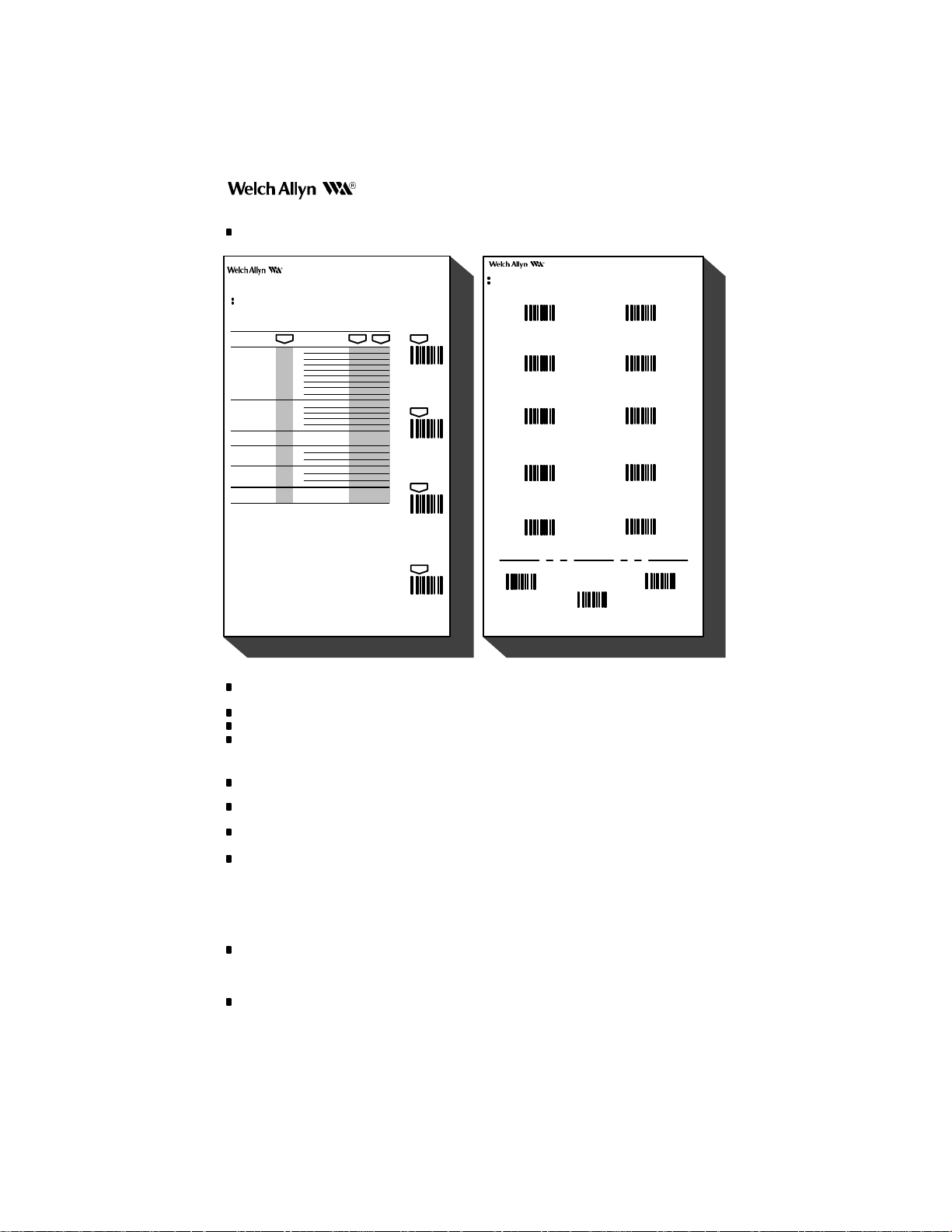
As a general overview of the programming menu. The programming menu consists of two basic components as
shown below.
Programming Menu
USE THIS PAGE
To select the pre–programmed asterisked (*) values by scanning DEFAULT symbol.
To enable or disable listed code selections.
scan scan
selections variables
UPC
ID = c
(HEX 63)
EAN
ID = d
(HEX 64)
UPC & EAN
Addenda Req’d.
MSI
ID = g
(HEX 67)
Plessey
ID = n
(HEX 6E)
DISABLE ALL
CODES (3)
Notes:
(1) * Designates DEFAULT selections.
(2) UPC Version D is not supported at this time.
(3) This option includes all industrial and stacked symbologies.
Version A
Version D(2)
Version E0
Version E1
Check Digit Xmit
Number System Xmit
Version E Expand
2–Digit Addenda
5–Digit Addenda
EAN/JAN 13
EAN/JAN 8
Check Digit Xmit
2–Digit Addenda
5–Digit Addenda
Enable Yes/No*
Enable
Minimum Length
Maximum Length
Enable
Minimum Length
Maximum Length
Are you sure?
scan
A
*Yes/No
No*
B
C
*Yes/No
*Yes/No
D
E
*Yes/No
F
*Yes/No
Yes/No*
G
H *Yes/No
*Yes/No
I
A
*Yes/No
B
*Yes/No
*Yes/No
C
DE*Yes/No
*Yes/No
Yes/No*
*04–Max
A
Min–48*
B
Yes/No*
*04–Max
A
Min–48*
B
Yes/No*
CODE
SELECTION II
(RETAIL)
scan
ENTER
scan
DEFAULT
scan
ESCAPE
USE THIS PAGE
In combination with the adjoining menu pages to program the unit.
The bar codes on this page correspond to symbols in shaded areas on adjoining menu pages. SCAN these bar codes in the sequence indicated on
menu page to program desired selections and variables.
Programming Menu
DIGITS
0 (YES)
1 (NO)
2
3
4
SYSTEM
BAR CODE CHART II
5
6
7
8
9
GUIDE
SAMPLE MENU PAGE
scan
EXIT
ESCAPE
BAR CODE CHART
OTHERS
EXIT
DEFAULT
MENU PAGE
Each menu page represents one section of the programming menu. Use individual menu pages in combination with
the bar code chart on the back page foldout to program the decoder.
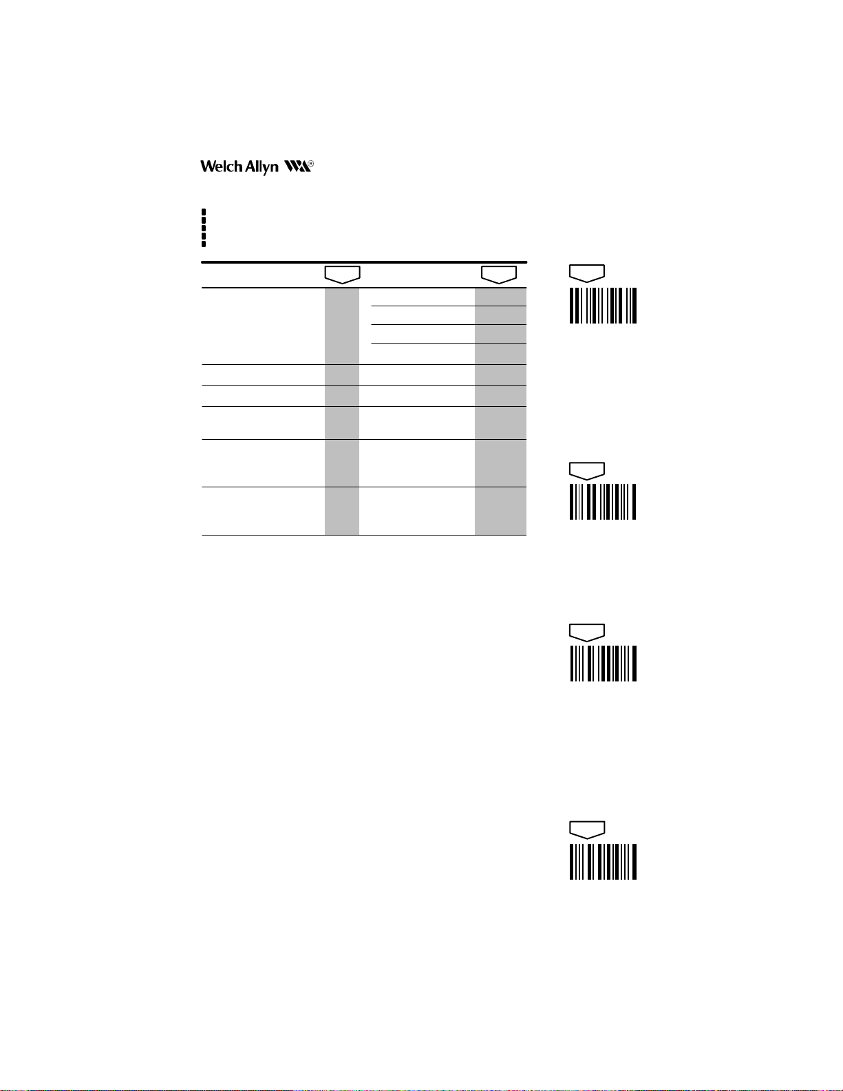
USE THIS PAGE – A summary of the programming options (parameters) of each menu page.
ENTER – Each menu page has its own unique ENTER bar code; scan this bar code to activate desired menu page.
DEFAULT – The DEFAULT bar code allows the user to independently default menu pages to asterisked (*) values
without affecting, in any way, the rest of the programming menu. Default values can be easily selected from the
desired menu pages by scanning the bar code sequence ENTER, DEFAULT, EXIT. Individual defaults for a specific
selection can be made by scanning ENTER, ROMAN NUMERAL, DEFAULT, EXIT.
ESCAPE – Use this bar code to cancel current programming sequence. All parameters remain as they were. Scan
ESCAPE to abort changes and exit from programming mode.
EXIT – Scanning this bar code ends programming selection. Go from one menu page to another by scanning a new
ENTER code (no need to scan EXIT between pages). Scan EXIT to save changes and end programming sequence.
SELECTIONS/VARIABLES – Lists all of the options available on each menu page. Following each option are
symbols in shaded areas. These symbols correspond to bar codes on the adjoining bar code chart.
NOTES – are provided to call out any unusual situations and/or refer you to necessary information or examples
elsewhere in the menu or manual.
Programming Note: Programming changes are in effect as soon as you make them! For example: changes to the
beeper volume can be heard instantly. Likewise, changes to the baud rate parameters occur as soon as the “ENTER
RS–232,” Roman Numeral “I,” and number (“0–6”) sequence has been scanned. EXIT will save the changes; ESCAPE
will restore the original settings. Take care that programming parameters match your terminal settings.
MENU PAGE FACING (Not Shown)
The page facing the menu is often used to supplement or clarify the material presented on the front of each menu
page. The information and examples found here are specific to the individual menu page and contain, in some cases,
charts and diagrams that must be used in order to determine the correct programming sequence.
BAR CODE DATA CHART
The bar codes on this chart are assigned to a ROMAN NUMERAL, LETTER, DIGIT, OR YES/NO symbol. These bar
codes correspond to the symbols in shaded areas on the menu pages and are scanned in various combinations to
enter programming sequences to the decoder. Bar codes on this page are meaningless unless an ENTER bar code
from one of the menu pages is first scanned. When an ENTER bar code is scanned, the bar code chart becomes
specific to that menu page and remains so until the EXIT bar code is scanned or another menu page is selected.
3
Page 5

BEEPER
SCANTEAM 3000/PDF Information/Examples
Volume
This programming selection provides control of the reader’s beeper volume. The beeper
volume may be set from low to high in four increments. Default = “2,” medium–high.
Beep on Power Up
When enabled, the reader will double beep each time the system is reset. When disabled,
the beeper will not sound whenever the system is reset. Default = enabled (“Yes”).
Beep on Good Read
When enabled, the reader will beep once following a successful decode. When disabled,
the beeper will not sound following the decode. Default = enabled (“Yes”).
Code 16K, Code 49: Click on Row Read
When enabled, the reader will click once after each row of a Code 16K or Code 49 stacked
bar code has been read. When disabled, the beeper will not sound after scanning rows of
Code 16K or Code 49 stacked bar code. Default = disabled (“No”).
PDF417: Ticking Indicates Scanning Progress
When enabled, the reader will emit a ticking sound as it scans a PDF417 symbol. The rate
of ticking is proportional to the rate of data collection. When disabled, the beeper will not
sound while scanning a PDF417 symbol. Default = disabled (“No”).
PDF417: Humming Indicates Decoder Is Busy
When enabled, the reader will emit a humming sound while it is decoding a PDF417
symbol. When disabled, the beeper will not sound while decoding a PDF417 symbol.
Default = enabled (“Yes”).
What the Beeper is Telling you:
As audible feedback, the PDF Capable reader provides six different beeps:
single beep, double beep, triple beep, click, tick, and hum.
Single Beep
Double Beep
Triple Beep
Click
Tick
Hum
One beep signals a successful barcode read.
Two beeps in succession indicate either:
• a hardware reset (as when the unit is first powered on)
• ENTER/EXIT/ESCAPE programming mode (when using the
Three quick beeps in succession indicate an error condition, as when an
illegal menu code is scanned, or when the serial input buffer overflows. Every
character sent to the PDF Capable reader is stored in a buffer. If the
characters arrive faster than the reader can process them, it is possible
(though rare) that the input buffer will completely fill up, and an overflow
occurs. See Technical Manual for more details.
A “Click” has the same pitch as a beep, but has a much shorter duration. The
click signals a successful row read for stacked codes 16K and 49. This
provides useful feedback when the codes are scanned using a wand. Such
feedback may not be as useful when using PDF Capable readers, since they
have been optimized to read stacked codes.
The “Tick” has the shortest duration, and no perceivable pitch. It is used to
indicate scanning progress while reading PDF417. A tick is initiated for every
32 PDF417 codewords read. A high rate of ticking corresponds to a high rate
of data collection, thus good printing and good scanning technique are
indicated by a high ticking rate.
Refer to the PDF Technical manual for printing/scanning suggestions. In general,
keep the scan line of the reader aligned with the rows of the symbol. Printing smaller
X–dimension and larger Y–dimension (row height) aids scanning ability.
The “Hum” is a steady tone with a lower pitch and volume than the beep, and a
variable duration. The PDF417 reader can’t scan while decoding PDF417.
When a great deal of error correction is required, the reader may appear to be
“locked up.” Humming indicates that the reader is busy decoding. Use the
ticking option for PDF417 to learn how to scan for optimum performance.
Careful scanning greatly decreases PDF417 decoding time.
programming menu pages).
4
Page 6
SCANTEAM 3000/PDF Programming Menu
USE THIS PAGE
To default this page to asterisked (*) values.
To set beeper volume.
To program beep on power up and/ or beep on good read.
To program click on row read for Code 16K and Code 49.
To program ticking or humming to indicate scanning/ decoding progress for PDF417.
BEEPER
selections variables
VOLUME
BEEP ON POWER UP
BEEP ON GOOD READ
CLICK ON ROW READ
(Code 16K, Code 49 only)
TICKING INDICATES
scan
Low
Medium–Low
Medium–High
High
Enable
Enable *Yes/No
Enable Yes/No*
Enable Yes/No*
SCANNING PROGRESS
(PDF417 only)
HUMMING INDICATES
Enable *Yes/No
DECODER IS BUSY
(PDF417 only)
Notes:
(1) * Denotes DEFAULT variables.
scan
0
1
2*
3
*Yes/No
scan
ENTER
scan
DEFAULT
scan
ESCAPE
scan
EXIT
5
Page 7

RS–232
SCANTEAM 3000/PDF Information/Examples
Baud Rate
This programming selection sets the baud rate from 600 bits per second to 38,400 bits per
second. Programming baud rate causes the data to be sent at the specified rate. Default =
9600 bits per second.
Character Format
This programming selection allows you to set the character format for number of data and
parity bits. PDF capable products support seven or eight bits of data and zero or one parity
bit per character. The number of start and stop bits is fixed at one each. If an application
requires only ASCII characters 0 through 127 decimal (text, digits, and punctuation), select
7 data bits. For applications requiring use of the full ASCII set, select 8 data bits per
character. Default = eight data bits, no parity, and one stop bit.
Note: PDF417 data is checked for accuracy before it is transmitted. This doesn’t
guarantee that errors won’t be introduced during data communication. A parity bit may be
added to each transmitted character as a means of character validation. A checksum
character may also added to the message as a postamble (suffix), for even stronger
security (see Preamble/Postamble menu page). The receiving device must be set up for
precisely the same character format as the reader, to ensure reliable communication.
Data Flow Control
Flow control may be necessary to handle the larger PDF417 messages. The PDF417
reader will normally transmit a message immediately following a successful decode. With
flow control selected, the receiver can enable/disable the reader’s transmitter. Default =
“None,” no data flow control option selected.
For example: suppose the receiver stores transmitted characters in a 512–byte buffer , yet
the PDF417 reader has a 1400–byte message to transmit. The receiver might take 510
characters into its buffer, then tell the reader to STOP transmitting. As the receiver
processes the message, space becomes available in the 512–byte buffer and the receiver
can tell the reader to STAR T transmitting again.
Two methods of flow control have been implemented in the PDF capable products:
RTS/CTS hardware handshaking, and an XON/XOFF protocol.
RTS/CTS Handshaking
This option will use two wires connected to both the reader and the receiver. The reader will
have control of the RTS line, the receiver controls the CTS line.
Whenever the reader has a message to send, it will raise (the voltage on) the Ready To
Send (RTS) line. (If the reader has no messages to send it will ground the RTS line.) When
the receiver wants to suspend transmission it should ground the CTS line. The reader
looks at the state of CTS prior to sending each character. When the receiver is willing to
accept a message from the reader it should raise (the voltage on) the Clear T o Send (CTS)
line. The reader will resume sending messages, continuing where it left off when the CTS
line was grounded.
XON/XOFF Protocol
This option uses only the transmit/receive lines between the reader and the receiver.
When the receiver wants to suspend transmission, it will send the XOFF character (ASCII
19 decimal) to the reader. When the receiver wants to resume transmission, it will send the
XON character (ASCII 17 decimal) to the reader. The reader will resume sending
messages, continuing where it left off when the XOFF character was sent.
6
Page 8
SCANTEAM 3000/PDF Programming Menu
USE THIS PAGE
To default this page to asterisked (*) values.
To set baud rate.
To program character format.
To program data flow control.
RS–232
selections variables
BAUD RATE
CHARACTER
FORMAT
DATA FLOW
CONTROL
Notes:
(1) * Denotes DEFAULT variables.
scan
600 bits/second
1200 bps
2400 bps
4800 bps
9600 bps 4*
19200 bps
38400 bps
7 Data, Space Parity, 1 Stop 0
7 Data, Mark Parity, 1 Stop 1
7 Data, Even Parity, 1 Stop 2
7 Data, Odd Parity, 1 Stop 3
8 Data, No Parity, 1 Stop 4*
8 Data, Mark Parity, 1 Stop 5
8 Data, Even Parity, 1 Stop 6
8 Data, Odd Parity, 1 Stop 7
None
RTS/CTS Handshaking
XON/XOFF Flow Control 2
scan
0
1
2
3
5
6
0*
1
scan
ENTER
scan
DEFAULT
scan
ESCAPE
scan
EXIT
7
Page 9

TRIGGER
Generally, a TRIGGER ON causes the reader to begin decoding, and a TRIGGER OFF
halts decoding. The meaning of TRIGGER ON and TRIGGER OFF depends on the trigger
mode.
SCANTEAM 3000/PDF Information/Examples
Autotrigger Enable
In autotrigger mode, the reader scans continuously. It does not, however , output decoded
messages continuously. Internal logic determines when to output a decoded message.
This decision is based on several factors, including the state of TRIGGER ON/OFF . In the
context of autotrigger mode, TRIGGER ON/OFF are defined as:
TRIGGER ON – The scanner senses the presence of several black/white elements
(does not yet know if pattern is decodable).
TRIGGER OFF – The scanner senses the lack of black/white elements.
The reader’s new autotrigger logic is aggressive, resulting in fast reads. It is
to TRIGGER OFF in order to read a
needs to TRIGGER OFF for about a quarter of a second.
new
code, but in order to reread the
not
same
necessary
code, one
Manual Trigger Enable
In manual trigger mode, a TRIGGER ON is required to activate scanning and decoding. In
the context of manual trigger mode, TRIGGER ON/OFF are defined as:
TRIGGER ON – (A) The trigger switch is pressed
command (ASCII 18 decimal) is sent to the reader.
TRIGGER OFF – (A) The trigger switch is released
command (ASCII 20 decimal) is sent to the reader.
In manual trigger mode it is necessary to TRIGGER OFF following a successful decode
before another code can be read. The scanning stops immediately following a successful
decode, but the reader is not TRIGGERED OFF until one of the conditions above has been
satisfied.
Note: If the scanner is triggered serially, it isn’t necessary to send the TRIGGER OFF
command.
A power–saving mode is available for hand–held readers having a hardware trigger in
manual trigger mode. All that is required is the proper cable. (Contact your sales
representative or refer to the IPWC Cable Matrix for hand–held CCD
constant/switched–power cable information.) On power–up, the reader senses if the
unit is using the switched–power cable, and goes immediately into a low–power mode.
Only the trigger–sensing circuitry is powered (current draw is 0.23 mA @ 5V for
3000–12C) until the trigger is pulled. Refer to the scanner’s T echnical Manual for specifics.
Note: Manual Trigger mode is not available in hand–held scanners having no trigger switch
(such as the 3000–0XC).
or
(B) The serial TRIGGER ON
or
(B) The serial TRIGGER OFF
8
Page 10

SCANTEAM 3000/PDF Programming Menu
USE THIS PAGE
To default this page to asterisked (*) values.
To set the trigger mode to autotrigger.
To set the trigger mode to manual trigger.
TRIGGER
selections
scan
AUTOTRIGGER ENABLE
MANUAL TRIGGER ENABLE
(For both hardware and serial triggering)
Notes:
(1) * Denotes DEFAULT selection.
scan
ENTER
scan
DEFAULT
scan
ESCAPE
scan
EXIT
9
Page 11

PREAMBLE/POSTAMBLE
SCANTEAM 3000/PDF Information/Examples
Preamble/Postamble
The scanner will transmit the decoded message after every successful bar code read. Y ou
have the option of adding characters before (preamble) and after (postamble) the bar code:
Transmitted data frame –>
Preamble PostambleBar Code Message
Characters for the preamble and postamble are selected by their hexadecimal ASCII
value, up to 8 characters each. In addition, special characters are available for code
identification and for error detection. Programming preamble/postambles is flexible,
allowing creative framing possibilities.
These preamble/postambles apply to all messages regardless of the symbology, and
cannot be assigned for a specific symbology. The special characters for Code ID
will
change to indicate the decoded symbology .
Note: HEX–ASCII and Symbology charts are shown below the Preamble/Postamble
Examples. Special Characters and their explanations are on following (menu) page.
Preamble/Postamble Examples:
1. The postamble defaults to a carriage return plus line feed:
<CR> <LF>Bar Code Message
If no postamble is desired, scan:
ENTER, , EXIT
Where:
ENTER (Preamble/Postamble) enters programming mode.
selects postamble programming and clears current postamble.
EXIT saves changes and exits programming mode.
2. T o frame a message with <STX> (start of transmission) and <ETX> (end of transmission):
<STX>
<ETX>Bar Code Message
First program the preamble, then the postamble, by scanning:
ENTER, , 0, 2, , 0, 3, EXIT
Where:
ENTER (Preamble/Postamble) enters programming mode.
selects preamble programming and clears current preamble.
02 represents the hexadecimal ASCII value for the <STX> character.
selects postamble programming and clears current postamble.
03 represents the hexadecimal ASCII value for the <ETX> character.
EXIT saves changes and exits programming mode.
HEX – ASCII CHART
NUL
00
SOH
STX
ETX
EOT
ENQ
ACK
BEL
BS
HT
LF
VT
FF
CR
SO
SI
DLE
01
DC1
02
DC2
03
DC3
04
DC4
05
NAK
06
SYN
07
ETB
08
CAN
09
EM
0A
SUB
0B
ESC
0C
FS
0D
GS
0E
RS
0F
US
SYMBOLOGY CHART
Symbology
Codabar
Code 39
UPC
EAN
Interleaved 2 of 5
Code ID
10
10
SP
20
0
11
!
ASCII
61
62
63
64
65
21
”
22
#
23
$
24
%
25
&
26
’
27
(
28
)
29
*
2A
+
2B
,
2C
–
2D
.
2E
/
2F
12
13
14
15
16
17
18
19
1A
1B
1C
1D
1E
1F
a
b
c
d
e
30
1
31
2
32
3
33
4
34
5
35
6
36
7
37
8
38
9
39
:
3A
;
3B
<
3C
=
3D
>
3E
?
3F
Symbology
Industrial 2 of 5
MSI code
Code 11
Code 93
Code 128
@
40
A
41
B
42
C
43
D
44
E
45
F
46
G
47
H
48
I
49
J
4A
K
4B
L
4C
M
4D
N
4E
O
4F
Code ID
f
g
h
i
j
ASCII
66
67
68
69
6A
P
50
Q
51
R
52
S
53
T
54
U
55
V
56
W
57
X
58
Y
59
Z
5A
[
5B
\
5C
]
5D
^
5E
_
5F
‘
a
b
c
d
e
f
g
h
i
j
k
l
m
n
o
Symbology
Code 49
Matrix 2 of 5
Plessey code
Code 16K
PDF417
60
61
62
63
64
65
66
67
68
69
6A
6B
6C
6D
6E
6F
Code ID
l
m
n
o
r
p
q
r
s
t
u
v
w
x
y
z
{
|
}
~
DEL
70
71
72
73
74
75
76
77
78
79
7A
7B
7C
7D
7E
7F
ASCII
6C
6D
6E
6F
72
Page 12

SCANTEAM 3000/PDF Programming Menu
USE THIS PAGE
To default this page to asterisked (*) values.
To program preamble/postamble variables.
PREAMBLE/POSTAMBLE
selections
PREAMBLE
(Prefix)
POSTAMBLE
(Suffix)
Notes:
(1) DEFAULT is NO preamble and <CR> <LF> postamble.
scan
variables
Up to EIGHT hexadecimal pairs,
00 through FF
Up to EIGHT hexadecimal pairs,
00 through FF
Special Characters
Hex
Character
80 Insert Code ID
81 Insert AIM Symbology ID and Modifier
85 Insert LRC Checksum as two printable hexadecimal
86 Insert LRC Checksum as a single byte
87 XX Set LRC Checksum = XX (hexadecimal)
Result
The 80 hex will be replaced by a single character
identifying the decoded barcode symbology .
See the Symbology Chart, facing page.
The 81 hex will be replaced by a three character string:
]CM
Where:
] is the symbology ID flag character
C is the symbology ID character
M is the modifier character
See AIM Guidelines on Symbology Identifiers for more
information.
characters plus a space
When placed at the end of a transmitted message, the
LRC checksum provides a modest amount of error
detection. The checksum is computed as the
Exclusive–Or of every transmitted character, after
being initialized to zero.
The LRC checksum can have any value 00 through FF
hexadecimal, but not all characters in this range are
printable. This option causes the LRC checksum to be
transmitted as three characters; two hexadecimal
numbers plus a space.
A single character is transmitted having a value 00
through FF hexadecimal.
For initializing the checksum to some value other than
zero, XX can be any value 00 through FF hexadecimal.
scan
ENTER
scan
DEFAULT
scan
ESCAPE
scan
EXIT
11
Page 13

CODE
SELECTION I
(INDUSTRIAL)
Symbology
Codabar
Code 39 S/S Xmit
Interleaved
2 of 5
Code 11 Check Digits The Code 11 specification recommends the use of two
12
Option Explanation
S/S Xmit
Check Char Req’d
Xmit Check Char
Concatenation
Concatenation Req’d
Check Char Req’d
Xmit Check Char
Full ASCII
Append Option
Check Digit Req’d
Xmit Check Digit
Note: Welch Allyn PDF Capable readers can autodiscriminate between
15 Symbologies. For maximum data security, disable the codes not used.
Data in a Codabar symbol is framed by a start and a stop
character. Since they are not considered part of the
message, they are not ordinarily transmitted.
For applications requiring enhanced security, a check
character may be used. When enabled, the reader will
assume that the last character is a check character, and
will use it to verify the accuracy of the scanned data. If no
error is detected, the data will be transmitted.
When required, the check character will be verified, but will
not normally be transmitted. Enable this option to transmit
the checksum, when planning to verify transmitted data.
Codabar provides an option for concatenating messages
of adjacent symbols. The reader can distinguish those
messages which are concatenated from those that are not.
Select “NO” to prevent concatenation.
With this option enabled the reader
concatenated symbols. If a particular application will
always use concatenation with Codabar, then this option is
recommended.
Data in a Code 39 Symbol is framed by a start and a stop
character. Since they are not considered part of the
message they are not ordinarily transmitted.
For applications requiring enhanced security, a check
character can be used. When enabled, the reader will
assume that the last character is a check character, and
will use it to verify the accuracy of the scanned data. If no
error is detected, the data will be transmitted.
When required, the check character will be verified, but will
not normally be transmitted. Enable this option to transmit
the checksum, when planning to verify transmitted data.
The code 39 specification provides a means of encoding
the full ASCII set of characters by using two–character
sequences made up of one of the four Code 39 characters
($ + % /) followed by one of the 26 letters as shown in the
Full ASCII Code 39 chart (on page 14). The reader cannot
distinguish Code 39 labels encoded in full ASCII mode
from those encoded in standard mode. Use this option to
direct the decoder which mode to assume.
The Code 39 specification provides a means of appending
data messages. If the first data character of a Code 39
symbol is a SPACE, then data following the SP ACE can be
appended to a storage buffer. PDF Capable readers don’t
have an append buffer; therefore this function isn’t
available. When append option is selected, any leading
SPACE is removed from the transmitted message.
For applications requiring enhanced data security, a check
character can be used. When enabled, the reader will
assume that the last digit is a check digit, and will use it to
verify the accuracy of the scanned data. If no errors are
detected the data will be transmitted.
When required, the check digit will be verified, but will not
normally be transmitted. Enable this option to transmit the
check digit, when planning to verify the transmitted data.
check digits. The PDF Capable reader may be
programmed to read Code 1 1 symbols with only one check
digit. The reader cannot autodiscriminate the number of
check digits encoded in a symbol.
SCANTEAM 3000/PDF Information/Examples
only
responds to
Page 14

SCANTEAM 3000/PDF Programming Menu
USE THIS PAGE
To select the pre–programmed asterisked (*) values by scanning DEFAULT symbol.
To enable or disable listed code selections.
CODE
SELECTION I
(INDUSTRIAL)
selections variables
CODABAR
ID = a (HEX 61)
CODE 39
ID = b (HEX 62)
2 OF 5
ID = e (HEX 65)
CODE 2 OF 5
ID = f (HEX 66)
MATRIX 2 OF 5
ID = m (HEX 6D)
CODE 11
ID = h (HEX 68)
CODE 93
ID = i (HEX 69)
CODE 128
ID = j (HEX 6A)
DISABLE ALL
scan scan
Enable
S/S Xmit
Check Char. Req’d
Xmit Check Char.
Concatenation D *Yes/No
Concatenation Req’d
Enable *Yes/No
S/S Xmit
Check Char. Req’d
Xmit Check Char.
Full ASCII
Append Option E Yes/No*
Enable *Yes/No
INTERLEAVED
Check Digit Req’d
Xmit Check Digit
Enable *Yes/No
Enable *Yes/No
Enable *Yes/No
# Check Digits A
2 Check Digits *Yes
1 Check Digit
Enable
Enable
Are you sure?
CODES (2)
scan
*Yes/No
A
Yes/No*
Yes/No*
B
C
Yes/No*
E
Yes/No*
A
Yes/No*
Yes/No*
B
C
Yes/No*
D
*Yes/No
A
Yes/No*
B Yes/No*
No
*Yes/No
*Yes/No
Yes/No*
scan
ENTER
scan
DEFAULT
scan
ESCAPE
scan
Notes:
(1) * Denotes DEFAULT variables.
(2) This option includes all retail and stacked symbologies.
EXIT
13
Page 15

CODE
SELECTION II
(RET AIL)
Symbology
UPC
EAN EAN/JAN 13
Option Explanation
Version A
Version D
Version E0
Version E1
Check Digit Xmit
Number System Xmit
Version E Expand
Addenda
EAN/JAN 8
Check Digit Xmit
Addenda
Note: Welch Allyn PDF Capable readers can autodiscriminate between
15 Symbologies. For maximum data security, disable the codes not used.
SCANTEAM 3000/PDF Information/Examples
Standard Version, used to encode a 12–digit number; the
first digit is the number system character, the next ten are
data characters, the last is a check character.
This Variable–length version is not supported by the PDF
Capable reader.
The zero–suppression version for number system 0
compacts UPC data into six digits.
No longer supported by the UPC specification because of
its similarity to EAN 13, this zero–suppression version
compacts UPC number system 1 data into six digits. The
PDF Capable readers can be programmed to read UPC
E1 as long as EAN 13 is disabled.
The check digit of a UPC symbol is normally transmitted,
though the reader can be programmed to suppress the
check digit.
The number system character of a UPC symbol is normally
transmitted, though the reader can be programmed to
suppress the check digit.
When this option is selected, the UPC E symbol is
expanded into the standard 12–digit format.
Two/ five digit addendas are supported; it is recommended
you leave them disabled unless they are specifically
required. If an addenda will
recommended you enable the UPC and EAN ADDENDA
REQUIRED Option. When enabled, symbols without the
addenda will not read.
A superset of UPC, EAN 13 encodes a 13–digit number;
12 data digits and a check digit.
EAN encodes an 8–digit number; 7 data digits and a check
digit.
The check digit of an EAN symbol is normally transmitted,
though the reader can be programmed to suppress the
check digit.
Two/ five digit addendas are supported; it is recommended
you leave them disabled unless they are specifically
required. If an addenda will
recommended you enable the UPC and EAN ADDENDA
REQUIRED Option. When enabled, symbols without the
addenda will not read.
always
always
be used it is
be used it is
FULL ASCII CODE 3 OF 9 CHART
NUL
%U
DLE
$P
SP
SOH
STX
ETX
EOT
ENQ
ACK
BEL
BS
HT
LF
VT
FF
CR
SO
SI
$A
$B
$C
$D
$E
$F
$G
$H
$I
$J
$K
$L
$M
$N
$O
DC1
DC2
DC3
DC4
NAK
SYN
ETB
CAN
EM
SUB
ESC
FS
GS
RS
US
$Q
$R
$S
$T
$U
$V
$W
$X
$Y
$Z
%A
%B
%C
%D
%E
SPACE
!
/A
”
/B
#
/C
$
/D
%
/E
&
/F
’
/G
(
/H
)
/I
*
/J
+
/K
,
/L
–
–
.
.
/
/O
14
P
P
‘
%W
p
0
0
@
%V
Q
Q
a
1
1
A
A
R
2
2
B
3
3
4
4
5
5
6
6
7
7
8
8
9
9
:
/Z
;
%F
<
%G
=
%H
>
%I
?
%J
B
C
C
D
D
E
E
F
F
G
G
H
H
I
I
J
J
K
K
L
L
M
M
N
N
O
O
R
S
S
T
T
U
U
V
V
W
W
X
X
Y
Y
Z
Z
[
%K
\
%L
]
%M
^
%N
_
%0
+A
b
+B
c
+C
d
+D
e
+E
f
+F
g
+G
h
+H
i
+I
j
+J
k
+K
l
+L
m
+M
n
+N
o
+O
q
r
s
t
u
v
w
x
y
z
{
|
}
~
DEL
+P
+Q
+R
+S
+T
+U
+V
+W
+X
+Y
+Z
%P
%Q
%R
%S
%T
Page 16

SCANTEAM 3000/PDF Programming Menu
USE THIS PAGE
To select the pre–programmed asterisked (*) values by scanning DEFAULT symbol.
To enable or disable listed code selections.
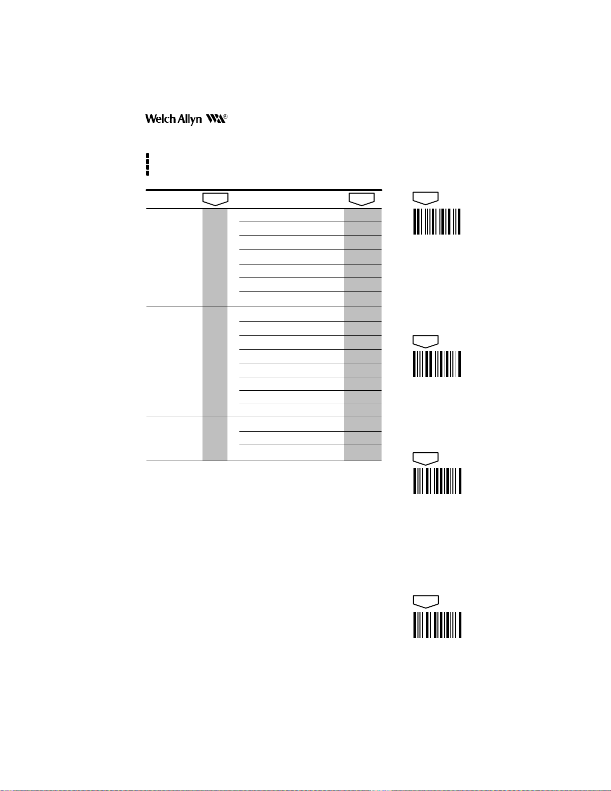
CODE
SELECTION II
(RET AIL)
selections variables
UPC
ID = c (HEX 63)
EAN
ID = d (HEX 64)
scan scan
Version A
Version D (2)
Version E0
Version E1 D *Yes/No
Check Digit Xmit
Number System Xmit F *Yes/No
Version E Expand G Yes/No*
2–Digit Addenda H Yes/No*
5–Digit Addenda I Y es/No*
EAN/JAN 13
EAN/JAN 8
Check Digit Xmit
2–Digit Addenda
5–Digit Addenda E Yes/No*
Enable Yes/No*
UPC & EAN
ADDENDA REQ’D.
MSI
ID = g (HEX 67)
PLESSEY
ID = n (HEX 6E)
DISABLE ALL
Enable Yes/No*
Enable *Yes/No
Are you sure?
CODES (3)
A
B
C
E
A
B
C
D
scan
*Yes/No
No*
*Yes/No
*Yes/No
*Yes/No
*Yes/No
*Yes/No
Yes/No*
Yes/No*
scan
ENTER
scan
DEFAULT
scan
ESCAPE
Notes:
(1) * Denotes DEFAULT variables.
(2) UPC Version D is not supported at this time.
(3) This option includes all industrial and stacked symbologies.
scan
EXIT
15
Page 17

CODE
SELECTION III
(ST ACKED)
Symbology
PDF417
Option Explanation
One–Pass
Notify–When–Certain
When–T o–Decode
SCANTEAM 3000/PDF Information/Examples
Note: Welch Allyn PDF Capable readers can autodiscriminate between
15 Symbologies. For maximum data security, disable the codes not used.
If this option is enabled, any partial PDF417 scan will be
cleared from memory upon a TRIGGER OFF. Normally
PDF scans are saved in memory until either a DECODE or
a new PDF417 label is scanned. It is not always possible
for the reader to know when a new label is introduced.
If this option is enabled, the reader sends out a message
(ASCII decimal 23) to notify the host system that a
successful PDF417 decode is certain; no more scanning is
required.
For Example: in a machine–mount system, a host
computer moves a PDF417 label back and forth in front of
the PDF Capable reader until the ASCII decimal 23 is
received. At that point scanning is completed, and the
decoded message will follow.
The PDF Capable reader must temporarily halt scanning
in order to perform PDF417 decoding. A refined algorithm
automatically predicts when enough information has been
scanned to insure a successful decode. If the scanned
data contains many errors, though, decoding cannot
succeed and more scanning is required.
In a machine–mount system with a predetermined scan
cycle, it may be an advantage to use
Decoding
attempt to decode PDF417 until a TRIGGER OFF . During
the predetermined scanning time, the reader is sure to be
collecting data.
. When this option is enabled the reader will not
Trigger–Off
Note: The PDF options were designed for machine–mount applications; however, they are
available, but not recommended, for the hand held reader.
16
Page 18

SCANTEAM 3000/PDF Programming Menu
USE THIS PAGE
To select the pre–programmed asterisked (*) values by scanning DEFAULT symbol.
To enable or disable listed code selections.
CODE
SELECTION III
(ST ACKED)
selections variables
PDF417
ID = r (HEX 72)
CODE 16K
ID = o (HEX 6F)
CODE 49
ID = l (HEX 6C)
DISABLE ALL
scan scan
Enable
One–Pass Option
Notify–When–Certain
When–To–Decode
Trigger–Off Decoding
Automatic
Enable *Yes/No
Enable *Yes/No
Are you sure?
A
B
C
CODES (2)
Notes:
(1) * Denotes DEFAULT variables.
(2) This option includes all industrial and retail symbologies.
scan
*Yes/No
Yes/No*
Yes/No*
0
1*
Yes/No*
scan
ENTER
scan
DEFAULT
scan
ESCAPE
scan
EXIT
17
Page 19

SERIAL MENU
SCANTEAM 3000/PDF Programming Menu
Using the Serial Menu
The serial menu may be used any time in place of the bar code menuing. The
serial menu is particularly useful for programming PDF capable machine–mount
readers that don’t have a hardware trigger.
Every programming menu code can be replaced by a two–character serial
command. A serial device programs the reader by sending the proper sequence
of serial commands. Use the menu pages to select the programming variables
your application requires.
For every menu code, the equivalent two–character serial command (and its
corresponding ASCII decimal value) are given in the SERIAL MENU CHARTS on
the following pages.
Example 1
For instance, if you want PDF417 enabled and all other bar code symbologies
disabled, use the CODES (STACKED) menu page. The correct sequence of
serial commands would be:
F <Ctrl–X> T <Ctrl–Y> 0 <Ctrl–Y> K <Ctrl–Y> 0 <Ctrl–Y> <SPC> <Ctrl–Y>
The above serial commands correspond to the selections and variables on the
programming menu page:
• ENTER code for that menu page
• “Disable All Codes” selection (Roman Numeral X)
• “Yes” (Digit 0) to disable all codes
• PDF417 selection (Roman Numeral I)
• “Y es” (Digit 0) to enable PDF417 decoding
• “EXIT” code for that menu page.
Example 2
If you wish to enable ticking to show PDF417 scanning progress, use the
BEEPER menu page. The correct sequence of serial commands would be:
A <Ctrl–X> O <Ctrl–Y> 0 <Ctrl–Y> <SPC> <Ctrl–Y>
The above serial commands correspond to the selections and variables on the
programming menu page:
• ENTER code for that menu page
• “Ticking Indicates Scanning Progress
• “Y es” (Digit 0) to enable this selection
• “EXIT” code for that menu page.
(PDF417)
” selection (Roman Numeral V)
Special Notes:
T ake care not to confuse the letter O and the number 0. Note also that the DEFAUL T code is
represented by a period (.) followed by <Ctrl–Y>. ASCII (decimal) values are included on the
SERIAL MENU CHARTS (below the corresponding serial command).
RS–232 parameter changes are immediately effected. The connected host serial device
must also change to the programmed selections accordingly. After changing baud rate it
may be necessary to wait a short amount of time for the serial port to stabilize. For this
reason bar code menuing is suggested for changing RS–232 parameters.
In manual trigger mode, two serial commands may be used to turn the trigger
on/off. The commands are:
ASCII 18 (decimal) Ctrl–R Trigger ON
ASCII 20 (decimal) Ctrl–T Trigger OFF
For PDF417, the notify–when–certain character is:
ASCII 23 (decimal) Ctrl–W Notify–When–Certain
18
Page 20

3000/PDF Programming Menu
USE THIS PAGE
In combination with the adjoining menu pages to program the 3000/PDF by sending serial commands from the host.
The serial command sequences on this page correspond to the bar code symbols on the BAR CODE CHARTS.
SERIAL MENU CHART I
ROMAN NUMERALS
K <Ctrl–Y>
75 25
I
L <Ctrl–Y>
76 25
II
M <Ctrl–Y>
77 25
III
N <Ctrl–Y>
78 25
IV
<– Serial Command –>
<– ASCII (decimal) –>
<– Serial Command –>
<– ASCII (decimal) –>
<– Serial Command –>
<– ASCII (decimal) –>
<– Serial Command –>
<– ASCII (decimal) –>
P <Ctrl–Y>
80 25
VI
Q <Ctrl–Y>
81 25
VII
R <Ctrl–Y>
82 25
VIII
S <Ctrl–Y>
83 25
IX
O <Ctrl–Y>
79 25
V
<– Serial Command –>
<– ASCII (decimal) –>
T <Ctrl–Y>
84 25
X
ENTER CODES: MENU PAGES
A <Ctrl–X> B <Ctrl–X>
65 24 66 24
BEEPER
G <Ctrl–X> C <Ctrl–X>
71 24 67 24
TRIGGER
<– Serial Command –>
<– ASCII (decimal) –>
RS–232
<– Serial Command –>
<– ASCII (decimal) –>
PREAMBLE/POSTAMBLE
19
Page 21

3000/PDF Programming Menu
USE THIS PAGE
In combination with the adjoining menu pages to program the 3000/PDF by sending serial commands from the host.
The serial command sequences on this page correspond to the bar code symbols on the BAR CODE CHARTS.
SERIAL MENU CHART II
LETTERS
A <Ctrl–Y>
65 25
A
B <Ctrl–Y>
66 25
B
C <Ctrl–Y>
67 25
C
D <Ctrl–Y>
68 25
D
<– Serial Command –>
<– ASCII (decimal) –>
<– Serial Command –>
<– ASCII (decimal) –>
<– Serial Command –>
<– ASCII (decimal) –>
<– Serial Command –>
<– ASCII (decimal) –>
F <Ctrl–Y>
70 25
F
G <Ctrl–Y>
71 25
G
H <Ctrl–Y>
72 25
H
I <Ctrl–Y>
73 25
I
20
E <Ctrl–Y>
69 25
E
<– Serial Command –>
<– ASCII (decimal) –>
J <Ctrl–Y>
ENTER CODES: MENU PAGES
D <Ctrl–X> E <Ctrl–X>
68 24 69 24
INDUSTRIAL CODES
STACKED CODES
<– Serial Command –>
<– ASCII (decimal) –>
F <Ctrl–X>
70 24
RETAIL CODES
<– Serial Command
<– ASCII (decimal)
74 25
J
Page 22

3000/PDF Programming Menu
USE THIS PAGE
In combination with the adjoining menu pages to program the 3000/PDF by sending serial commands from the host.
The serial command sequences on this page correspond to the bar code symbols on the BAR CODE CHARTS.
SERIAL MENU CHART III
DIGITS
0 <Ctrl–Y>
48 25
0 (YES)
1 <Ctrl–Y>
49 25
1 (NO)
2 <Ctrl–Y>
50 25
2
3 <Ctrl–Y>
51 25
3
<– Serial Command –>
<– ASCII (decimal) –>
<– Serial Command –>
<– ASCII (decimal) –>
<– Serial Command –>
<– ASCII (decimal) –>
<– Serial Command –>
<– ASCII (decimal) –>
5 <Ctrl–Y>
53 25
5
6 <Ctrl–Y>
54 25
6
7 <Ctrl–Y>
55 25
7
8 <Ctrl–Y>
56 25
8
4 <Ctrl–Y>
52 25
4
<– Serial Command –>
<– ASCII (decimal) –>
9 <Ctrl–Y>
57 25
9
OTHERS
* <Ctrl–Y> <SPC> <Ctrl–Y>
42 25 32 25
ESCAPE
<– Serial Command –>
<– ASCII (decimal) –>
. <Ctrl–Y>
46 25
DEFAULT
EXIT
<– Serial Command
<– ASCII (decimal)
21
Page 23

SAMPLE BAR CODES
This page contains bar code symbols in some of the most commonly used symbologies. You may use these codes
to test that your system is properly programmed for a particular symbology.
Code 39
SCANTEAM 3000 PDF Programming Menu
TEST–SHEET
Code 2 of 5
123456
Plessey
9876
Code 11
11223344
MSI
Interleaved 2 of 5
1234567890
Matrix 2 of 5
6543210
Codabar
0013557900
Code 128
CODE 128<BEL>
44332211
EAN–13
9780330290951
UPC–A
031323120786
PDF417
WELCH ALLYN IS PDF CAPABLE!
5 add on
56098
Page 24

3000/PDF Programming Menu
USE THIS PAGE
In combination with the adjoining menu pages to program the 3000/PDF.
The bar codes on this page correspond to symbols in shaded areas on adjoining menu pages. SCAN these bar
codes in the sequence indicated on menu page to program desired selections and variables.
BAR CODE CHART I
ROMAN NUMERALS
I
II
III
IV
VI
VII
VIII
IX
23
BEEPER
V
ENTER CODES: MENU PAGES
TRIGGER
X
RS–232
PREAMBLE/POSTAMBLE
Page 25

3000/PDF Programming Menu
USE THIS PAGE
In combination with the adjoining menu pages to program the 3000/PDF.
The bar codes on this page correspond to symbols in shaded areas on adjoining menu pages. SCAN these bar
codes in the sequence indicated on menu page to program desired selections and variables.
BAR CODE CHART II
LETTERS
A
B
C
D
F
G
H
I
E
INDUSTRIAL CODES
J
ENTER CODES: MENU PAGES
RETAIL CODES
STACKED CODES
Page 26

3000/PDF Programming Menu
USE THIS PAGE
In combination with the adjoining menu pages to program the 3000/PDF.
The bar codes on this page correspond to symbols in shaded areas on adjoining menu pages. SCAN these bar
codes in the sequence indicated on menu page to program desired selections and variables.
BAR CODE CHART III
DIGITS
0 (YES)
1 (NO)
2
3
5
6
7
8
ESCAPE
4
9
OTHERS
EXIT
DEFAULT
Page 27

3000/PDF/PM
Rev B
4619 Jordan Road
P.O. Box 187
Skaneateles Falls, New York 13153–0187
 Loading...