

Page 1
Vital Signs Monitor
300 Series
Directions for Use
Software version 1.2X
Page 2

ii Welch Allyn Vital Signs Monitor 300 Series
Copyright 2005 Welch Allyn. All rights are reserved. No one is permitted to reproduce or duplicate, in any
form, this manual or any part thereof without permission from Welch Allyn.
Welch Allyn assumes no responsibility for any injury to anyone, or for any illegal or improper use of the
product, that may result from failure to use this product in accordance with the instructions, cautions,
warnings, or statement of intended use published in this manual.
®
Welch Allyn
and Flexible Monitoring® are registered trademarks of Welch Allyn. FlexNet™ is a trademark
of Welch Allyn.
®
, LNOP®, and Masimo® are registered trademarks of Masimo Corporation. Possession or purchase of
SET
a Masimo SpO
-equipped monitor does not convey any express or implied license to use the device with
2
unauthorized sensors or cables which would, alone or in combination with this device, fall within the
scope of one or more of the patents relating to this device.
Software in this product is Copyright 2005 Welch Allyn or its vendors. All rights are reserved. The software
is protected by United States of America copyright laws and international treaty provisions applicable
worldwide. Under such laws, the licensee is entitled to use the copy of the software incorporated with
this instrument as intended in the operation of the product in which it is embedded. The software may not
be copied, decompiled, reverse-engineered, disassembled or otherwise reduced to human-perceivable
form. This is not a sale of the software or any copy of the software; all right, title and ownership of the
software remains with Welch Allyn or its vendors.
For information about any Welch Allyn product, please call Welch Allyn Technical Support:
USA + 1 315 685 4560
800 535 6663
Canada 800 561 8797 China + 86 216 327 9631
European Call Center + 353 46 906 7790 France + 33 15 569 5849
Germany + 49 747 792 7186 Japan + 81 33 219 0071
Latin America + 1 305 669 9003 Netherlands + 31 15 750 5000
Singapore + 65 6419 8100 South Africa + 27 11 777 7555
United Kingdom + 44 207 365 6780 Sweden + 46 85 853 6551
Reorder Part Number 810-22
50-XX
Manual Part Number 810-2222-0
1 Rev A, 02/2006
Australia + 61 29 638 3000
800 074 793
Welch Allyn
8500 SW Creekside Place
Beaverton, Oregon 97008-7107
www.monitoring.welchallyn.com
Printed in USA
Page 3

Contents
1 - General Information . . . . . . . . . . . . . . . . . . . . . . . . . . . . . . . . . . . . . . 1
iii
About This Manual . . . . . . . . . . . . . . . . . . . . . . . . . . . . . . . . . . . . . . . . . . . . . . . . 1
Intended Use . . . . . . . . . . . . . . . . . . . . . . . . . . . . . . . . . . . . . . . . . . . . . . . . . . . . 1
Symbols . . . . . . . . . . . . . . . . . . . . . . . . . . . . . . . . . . . . . . . . . . . . . . . . . . . . . . . . 2
Product Overview . . . . . . . . . . . . . . . . . . . . . . . . . . . . . . . . . . . . . . . . . . . . . . . . . 4
Warnings and Cautions. . . . . . . . . . . . . . . . . . . . . . . . . . . . . . . . . . . . . . . . . . . . . 5
General Warnings. . . . . . . . . . . . . . . . . . . . . . . . . . . . . . . . . . . . . . . . . . . . . . 5
General Cautions . . . . . . . . . . . . . . . . . . . . . . . . . . . . . . . . . . . . . . . . . . . . . . 6
Displays, Indicators, Controls, and Connections. . . . . . . . . . . . . . . . . . . . . . . . . . 7
Numeric Measurement and Message Displays . . . . . . . . . . . . . . . . . . . . . . . 7
Status Indicators . . . . . . . . . . . . . . . . . . . . . . . . . . . . . . . . . . . . . . . . . . . . . . 8
Function Controls . . . . . . . . . . . . . . . . . . . . . . . . . . . . . . . . . . . . . . . . . . . . . . 9
Connections . . . . . . . . . . . . . . . . . . . . . . . . . . . . . . . . . . . . . . . . . . . . . . . . . 10
2 - Setup . . . . . . . . . . . . . . . . . . . . . . . . . . . . . . . . . . . . . . . . . . . . . . . . . 11
Connections . . . . . . . . . . . . . . . . . . . . . . . . . . . . . . . . . . . . . . . . . . . . . . . . . . . . 11
Connecting AC Power . . . . . . . . . . . . . . . . . . . . . . . . . . . . . . . . . . . . . . . . . 11
Connecting the NIBP Cuff Hose. . . . . . . . . . . . . . . . . . . . . . . . . . . . . . . . . . 13
Connecting the Temperature Probe Cable . . . . . . . . . . . . . . . . . . . . . . . . . . 14
Connecting and Disconnecting the SpO
Power On, Power-on Self-Test, and Power Off . . . . . . . . . . . . . . . . . . . . . . . . . . 17
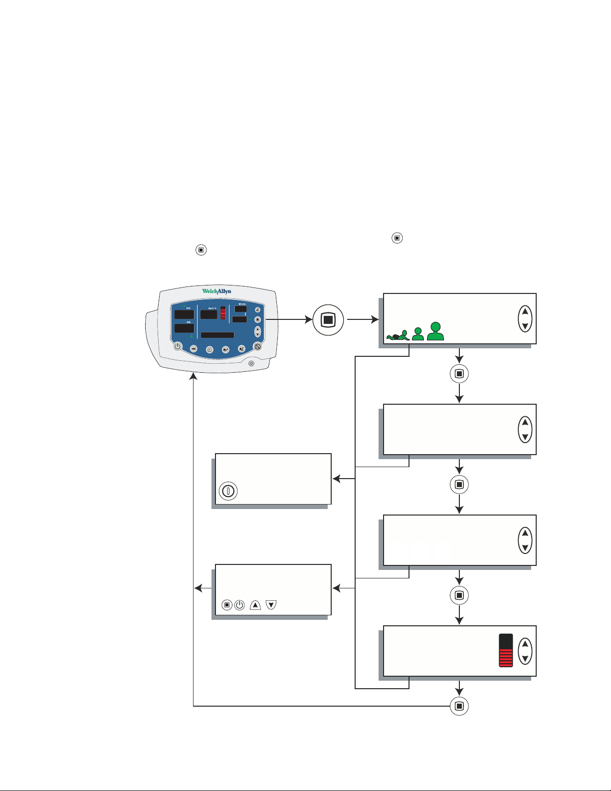
Configuring Operating Parameters . . . . . . . . . . . . . . . . . . . . . . . . . . . . . . . . . . . 18
How to Use the Menu System . . . . . . . . . . . . . . . . . . . . . . . . . . . . . . . . . . 18
Changing the Time and Date . . . . . . . . . . . . . . . . . . . . . . . . . . . . . . . . . . . . 22
Changing the Patient Type . . . . . . . . . . . . . . . . . . . . . . . . . . . . . . . . . . . . . . 24
MAP Measurement Enable and Disable . . . . . . . . . . . . . . . . . . . . . . . . . . . 25
Changing the NIBP Measurement Units . . . . . . . . . . . . . . . . . . . . . . . . . . . 26
Changing Temperature Type and Measurement Units . . . . . . . . . . . . . . . . . 27
Changing the Volume of the Pulse Tone . . . . . . . . . . . . . . . . . . . . . . . . . . . 28
Selecting Stream or Batch Printing. . . . . . . . . . . . . . . . . . . . . . . . . . . . . . . . 29
Sensor Cable . . . . . . . . . . . . . . . 15
2
3 - Patient Monitoring . . . . . . . . . . . . . . . . . . . . . . . . . . . . . . . . . . . . . . 31
Monitoring Blood Pressure . . . . . . . . . . . . . . . . . . . . . . . . . . . . . . . . . . . . . . . . . 31
NIBP Preparation . . . . . . . . . . . . . . . . . . . . . . . . . . . . . . . . . . . . . . . . . . . . . 32
Manual NIBP Measurement. . . . . . . . . . . . . . . . . . . . . . . . . . . . . . . . . . . . . 34
Automatic NIBP Measurement . . . . . . . . . . . . . . . . . . . . . . . . . . . . . . . . . . 35
Monitoring Pulse Rate . . . . . . . . . . . . . . . . . . . . . . . . . . . . . . . . . . . . . . . . . . . . 38
Monitoring SpO
Warnings and Cautions — SpO
. . . . . . . . . . . . . . . . . . . . . . . . . . . . . . . . . . . . . . . . . . . . . . . . . 39
2
. . . . . . . . . . . . . . . . . . . . . . . . . . . . . . . . . 39
2
Page 4

iv Contents Welch Allyn Vital Signs Monitor 300 Series
SpO2 Monitoring Procedure . . . . . . . . . . . . . . . . . . . . . . . . . . . . . . . . . . . . . 40
Monitoring Temperature . . . . . . . . . . . . . . . . . . . . . . . . . . . . . . . . . . . . . . . . . . . 42
Warnings and Cautions — Temperature. . . . . . . . . . . . . . . . . . . . . . . . . . . . 42
Setting the Temperature Measurement Type. . . . . . . . . . . . . . . . . . . . . . . . 43
Loading a Probe Cover . . . . . . . . . . . . . . . . . . . . . . . . . . . . . . . . . . . . . . . . . 44
Ejecting a Used Probe Cover . . . . . . . . . . . . . . . . . . . . . . . . . . . . . . . . . . . . 44
Predictive Temperature Measurement . . . . . . . . . . . . . . . . . . . . . . . . . . . . . 44
Monitored Temperature Measurement . . . . . . . . . . . . . . . . . . . . . . . . . . . . 50
Thermometer and Probe Cleaning Procedure . . . . . . . . . . . . . . . . . . . . . . . 51
Removable Probe Well Cleaning Procedure . . . . . . . . . . . . . . . . . . . . . . . . . 51
4 - Alarms and Alerts . . . . . . . . . . . . . . . . . . . . . . . . . . . . . . . . . . . . . . . 53
Responding to a Patient Alarm . . . . . . . . . . . . . . . . . . . . . . . . . . . . . . . . . . . . . . 53
Responding to an Equipment Alert . . . . . . . . . . . . . . . . . . . . . . . . . . . . . . . . . . . 54
Recoverable Temperature, NIBP, or SpO
Recoverable SpO
Recoverable NIBP Alert—Escalated. . . . . . . . . . . . . . . . . . . . . . . . . . . . . . . 54
Nonrecoverable Alerts . . . . . . . . . . . . . . . . . . . . . . . . . . . . . . . . . . . . . . . . . 55
Alarm Indicators . . . . . . . . . . . . . . . . . . . . . . . . . . . . . . . . . . . . . . . . . . . . . . . . . 56
Setting Alarms . . . . . . . . . . . . . . . . . . . . . . . . . . . . . . . . . . . . . . . . . . . . . . . . . . 56
Nurse Call . . . . . . . . . . . . . . . . . . . . . . . . . . . . . . . . . . . . . . . . . . . . . . . . . . . . . . 59
Error Codes. . . . . . . . . . . . . . . . . . . . . . . . . . . . . . . . . . . . . . . . . . . . . . . . . . . . . 60
Alert—Escalated . . . . . . . . . . . . . . . . . . . . . . . . . . . . . . 54
2
Alert—Not Escalated . . . . . . . . . 54
2
5 - Reviewing Patient Data. . . . . . . . . . . . . . . . . . . . . . . . . . . . . . . . . . . 61
Displaying Stored Patient Data . . . . . . . . . . . . . . . . . . . . . . . . . . . . . . . . . . . . . . 61
Printing Patient Data . . . . . . . . . . . . . . . . . . . . . . . . . . . . . . . . . . . . . . . . . . . . . . 61
To Start and Stop Printing. . . . . . . . . . . . . . . . . . . . . . . . . . . . . . . . . . . . . . . 62
Batch Printing . . . . . . . . . . . . . . . . . . . . . . . . . . . . . . . . . . . . . . . . . . . . . . . . 62
Stream Printing. . . . . . . . . . . . . . . . . . . . . . . . . . . . . . . . . . . . . . . . . . . . . . . 62
Printer Output. . . . . . . . . . . . . . . . . . . . . . . . . . . . . . . . . . . . . . . . . . . . . . . . 63
Erasing Patient Data . . . . . . . . . . . . . . . . . . . . . . . . . . . . . . . . . . . . . . . . . . . . . . 67
Erasing Data Before Changing the Date and Time. . . . . . . . . . . . . . . . . . . . 67
Erasing Data During Normal Operation . . . . . . . . . . . . . . . . . . . . . . . . . . . . 67
Replacing the Printer Paper Supply. . . . . . . . . . . . . . . . . . . . . . . . . . . . . . . . . . . 68
6 - Operator Maintenance . . . . . . . . . . . . . . . . . . . . . . . . . . . . . . . . . . . 69
Cleaning . . . . . . . . . . . . . . . . . . . . . . . . . . . . . . . . . . . . . . . . . . . . . . . . . . . . . . . 69
Storage . . . . . . . . . . . . . . . . . . . . . . . . . . . . . . . . . . . . . . . . . . . . . . . . . . . . . . . . 69
Recycling Monitor Components . . . . . . . . . . . . . . . . . . . . . . . . . . . . . . . . . . . . . 70
Within the EU . . . . . . . . . . . . . . . . . . . . . . . . . . . . . . . . . . . . . . . . . . . . . . . . 70
Outside the EU. . . . . . . . . . . . . . . . . . . . . . . . . . . . . . . . . . . . . . . . . . . . . . . 70
7 - Reference . . . . . . . . . . . . . . . . . . . . . . . . . . . . . . . . . . . . . . . . . . . . . . 71
Battery Operation . . . . . . . . . . . . . . . . . . . . . . . . . . . . . . . . . . . . . . . . . . . . . . . . 71
Battery Low Warning . . . . . . . . . . . . . . . . . . . . . . . . . . . . . . . . . . . . . . . . . . 71
Battery Failure . . . . . . . . . . . . . . . . . . . . . . . . . . . . . . . . . . . . . . . . . . . . . . . 71
Battery Replacement . . . . . . . . . . . . . . . . . . . . . . . . . . . . . . . . . . . . . . . . . . 72
Monitor Specifications . . . . . . . . . . . . . . . . . . . . . . . . . . . . . . . . . . . . . . . . . . . . 73
Page 5

Directions for Use Contents v
Performance. . . . . . . . . . . . . . . . . . . . . . . . . . . . . . . . . . . . . . . . . . . . . . . . . 73
Physical . . . . . . . . . . . . . . . . . . . . . . . . . . . . . . . . . . . . . . . . . . . . . . . . . . . . 75
Electrical. . . . . . . . . . . . . . . . . . . . . . . . . . . . . . . . . . . . . . . . . . . . . . . . . . . . 76
Environmental . . . . . . . . . . . . . . . . . . . . . . . . . . . . . . . . . . . . . . . . . . . . . . . 77
Nurse Call. . . . . . . . . . . . . . . . . . . . . . . . . . . . . . . . . . . . . . . . . . . . . . . . . . . 81
Factory Default Settings . . . . . . . . . . . . . . . . . . . . . . . . . . . . . . . . . . . . . . . . . . . 82
Limited Warranty . . . . . . . . . . . . . . . . . . . . . . . . . . . . . . . . . . . . . . . . . . 83
Index . . . . . . . . . . . . . . . . . . . . . . . . . . . . . . . . . . . . . . . . . . . . . . . . . . . . 85
Page 6

vi Contents Welch Allyn Vital Signs Monitor 300 Series
Page 7

1
1
General Information
About This Manual
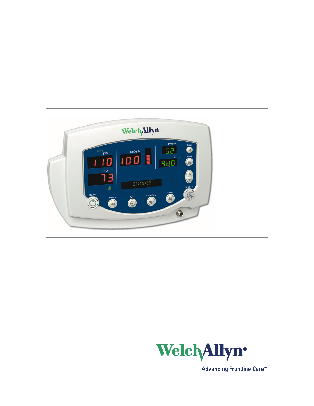
This manual contains information about the Welch Allyn Vital Signs Monitor 300 Series
monitor. The series includes the following models:
Model Features Model Features
53000 Standard (NIBP, Pulse Rate, and MAP) 53S00 Standard + Masimo SpO
5300P Standard + Printer 53ST0 Standard + Masimo SpO
530T0 Standard + Temperature 53S0P Standard + Masimo SpO
530TP Standard + Temperature + Printer 53STP Standard + Masimo SpO
All operators must read and understand this manual before using the monitor.
All technicians and other service personnel must read and understand this manual before
attempting to set up, configure, troubleshoot, or service the monitor.
All information in this manual, including the illustrations, is based on a monitor configured
with the Temperature, SpO
of these options, then some information in this manual does not apply.
2
+ Temperature
2
+ Printer
2
+ Temperature + Printer
2
, and Printer options. If your monitor configuration lacks any
2
Intended Use
The VSM series of monitors are intended to be used by clinicians and medically qualified
personnel for monitoring of noninvasive blood pressure, pulse rate, body temperature,
noninvasive functional oxygen saturation of arteriolar hemoglobin (SpO
temperature in normal and axillary modes of neonatal, pediatric and adult patients.
The most likely locations for patients to be monitored are general med/surg. floors,
general hospital and alternate care environments. This device is available for sale only
upon the order of a physician or licensed health care professional.
), and body
2
Page 8
2 Chapter 1 General Information Welch Allyn Vital Signs Monitor 300 Series
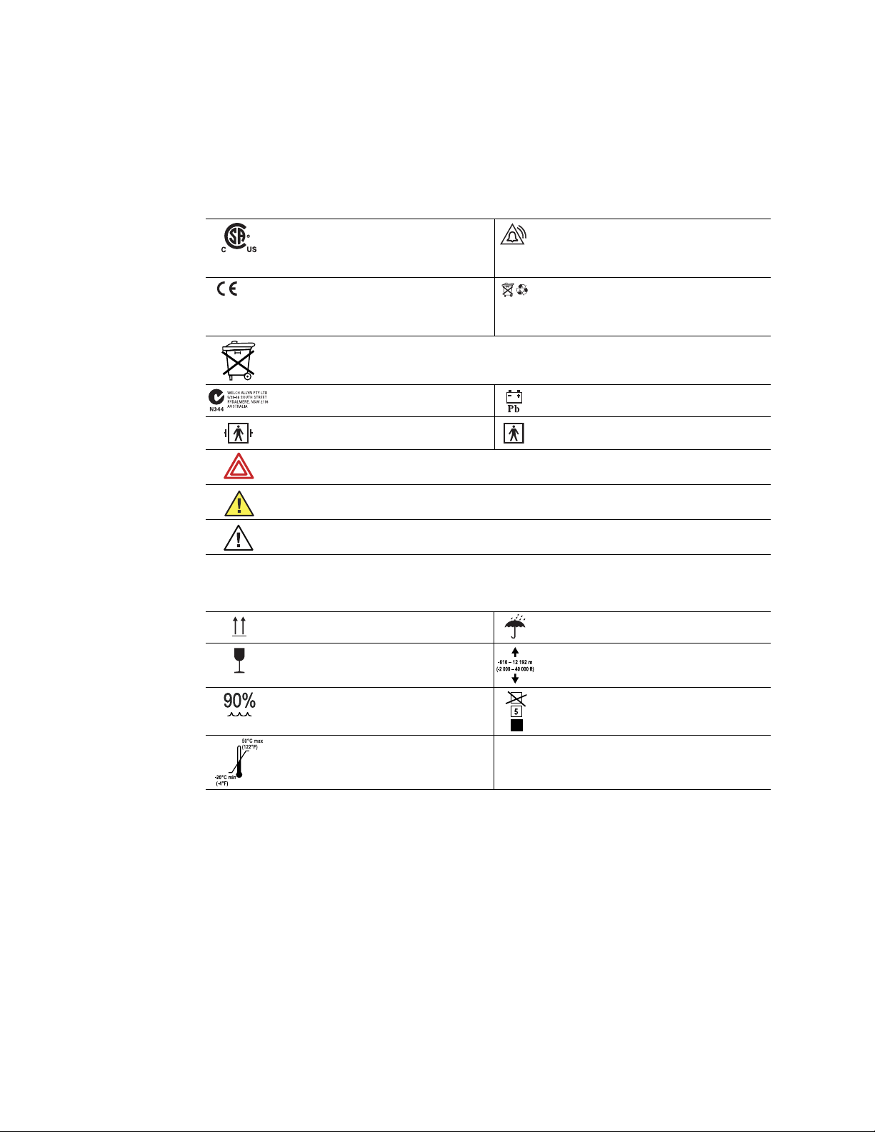
Symbols
The symbols illustrated on the following pages appear on the monitor or in this document.
Table 1. Symbols: Certification and Operation
This device has been tested and certified by
the Canadian Standards Association
International to comply with applicable U.S.
and Canadian medical safety standards.
The CE Mark and Notified Body Registration
0123
Number signify that the device meets all
essential requirements of the European
Medical Device Directive 93/42/EEC.
Recycle the monitor and battery separately from other disposables. (See “Recycling Monitor Components”
on page 70.)
Australian Registered Importer Sealed lead-acid battery, 6V 4 Ah
Patient connections (NIBP/Temp) are Type BF,
and protected against defibrillation.
WARNING Indicates conditions that could lead to illness, injury, or death.
Caution In this manual, indicates conditions that could damage equipment or other property.
Caution On the product, means “Consult accompanying documentation.”
Table 2. Symbols: Shipping, Storing, and Environment
Keep this end of the package or shipping
crate up.
Fragile contents—handle with care. Do not subject the monitor to altitudes outside
Urgent alarm notification (output to Nurse Call
system)
Recycle used batteries properly and in
accordance with local regulations.
Do not dispose of batteries in refuse containers.
Patient connections (SpO2) are Type BF.
Protect the monitor from exposure to rain.
these limits.
Do not expose the monitor to relative
humidity above this limit.
Do not expose the monitor to temperatures
outside these limits.
Limit stacking to this number of units.
Page 9

Directions for Use Chapter 1 General Information 3
Table 3. Symbols: Connectors
Temperature Probe Cable Connector SpO2 SpO2 Sensor Cable Connector
RS232 Cable Connector AC Power Adapter Cable Connector
Nurse Call Cable Connector NIBP Hose Connector
Table 4. Symbols: Printer Door
Press to open the printer door Load paper this direction
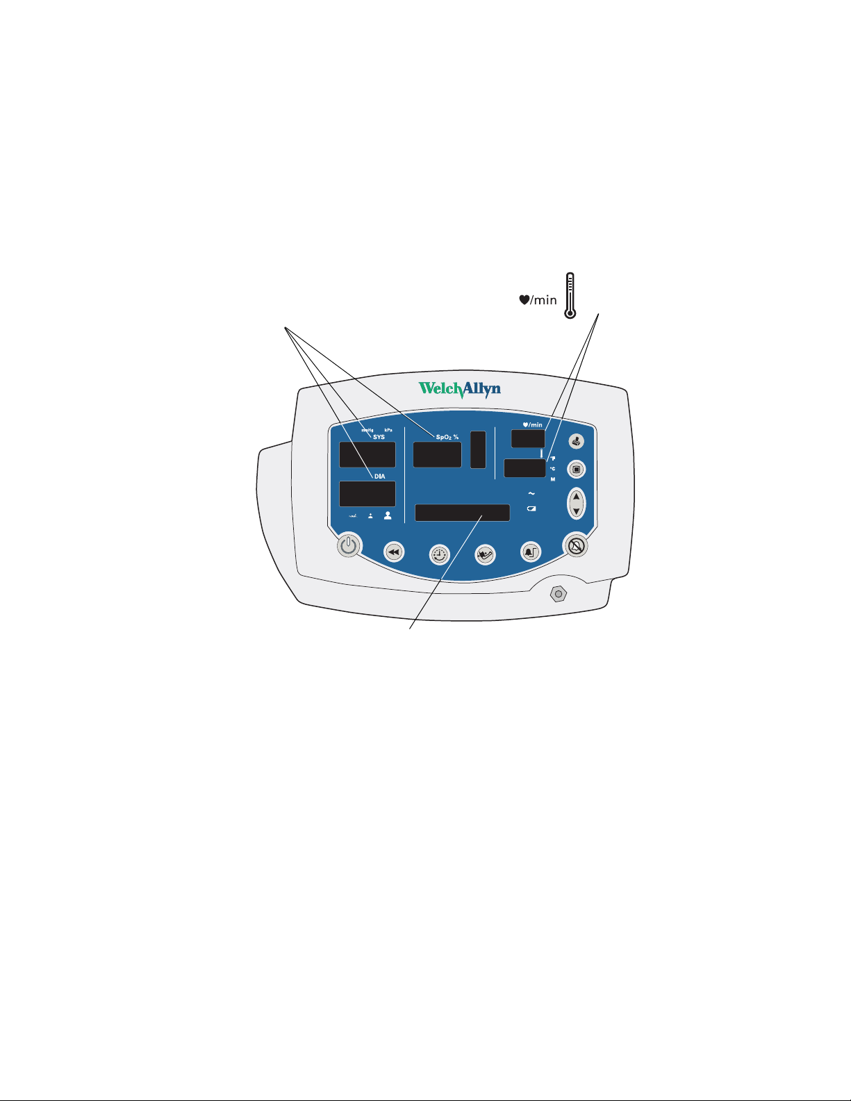
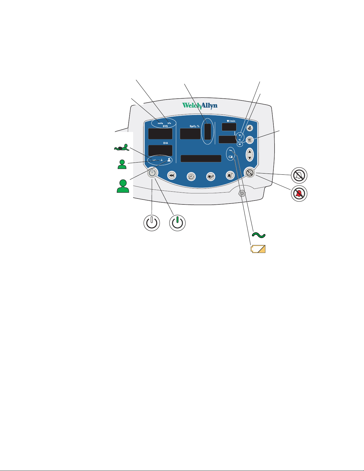
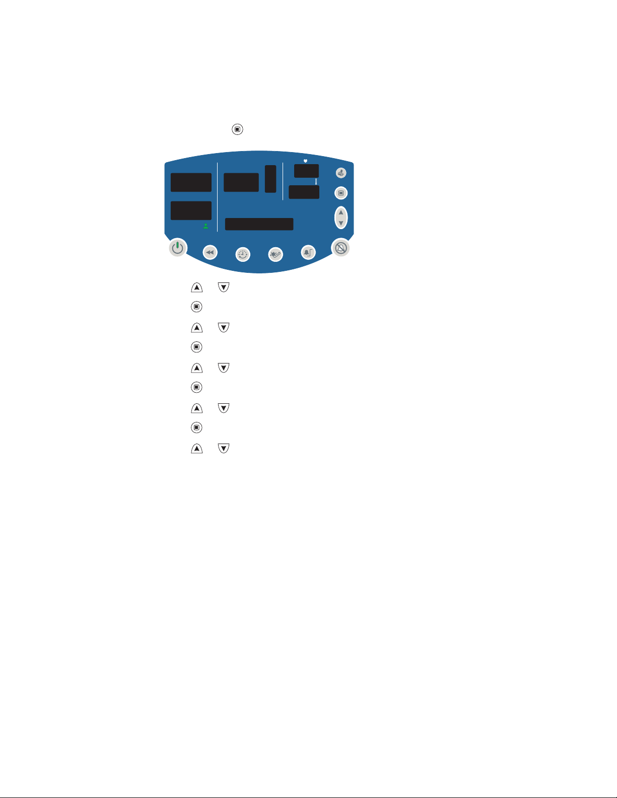
The functions of the monitor front panel controls illustrated here are described in detail
elsewhere in this document.
Table 5. Front Panel Controls
Set alarm limits Power on/off
Silence alarms Print patient data
Scroll up/down
Scroll forward/back
Increase/decrease value
(The scroll icon appears as these two arrows
in the documentation.)
Set an NIBP automatic measurement interval Start/stop an NIBP cycle (AUTO button)
Cycle to the next menu selections
Review patient data
Page 10
4 Chapter 1 General Information Welch Allyn Vital Signs Monitor 300 Series
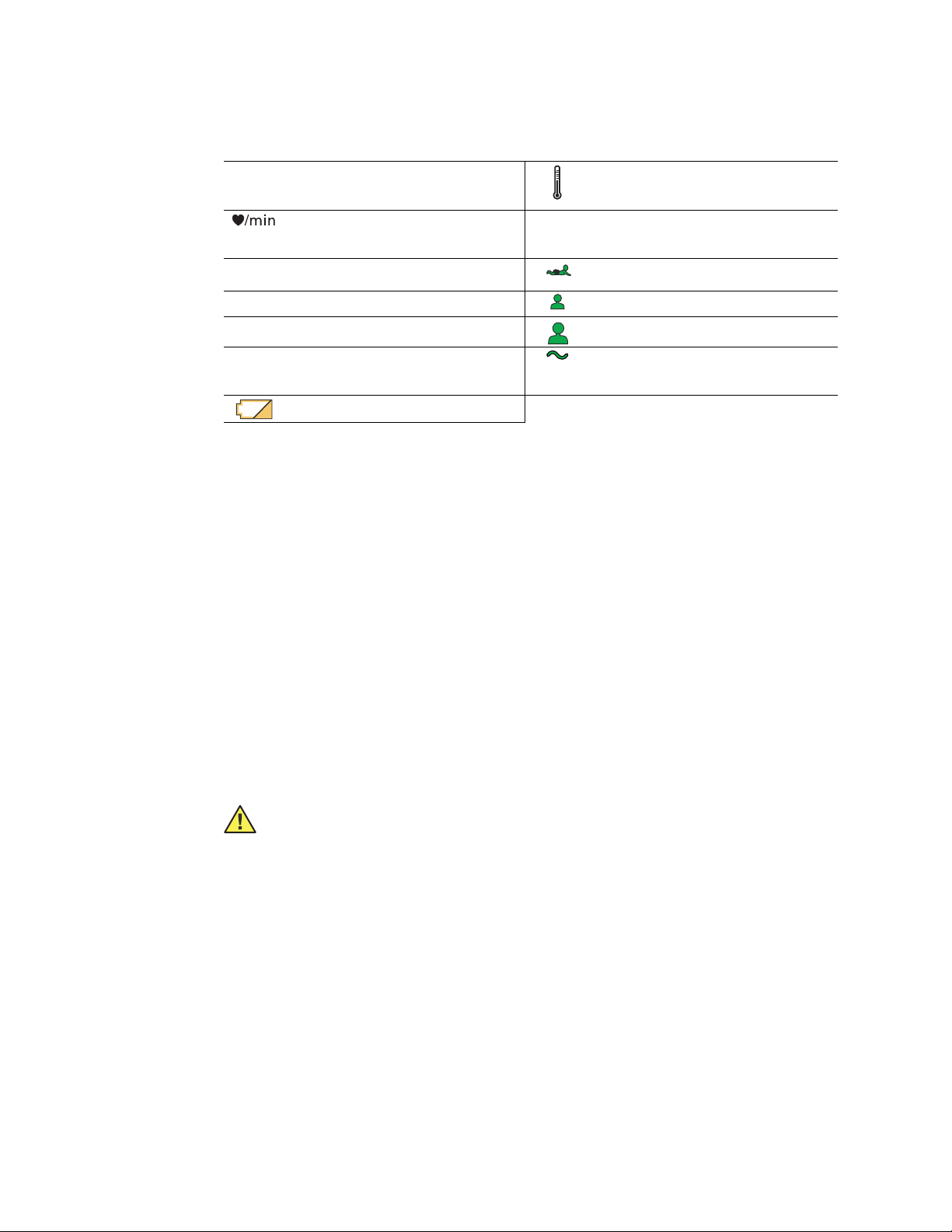
ºC
ºF
M
Table 6. Front Panel Displays and Indicators
SYS
DIA
SpO2
message
window
ºC
ºF
M
Systolic pressure
Diastolic pressure
Arterial hemoglobin oxygen saturation
Pulse rate pulse
amplitude
indicator
MAP (mean arterial pressure) Neonatal
Degrees Celsius Pediatric
Degrees Fahrenheit Adult
Monitored temperature AC power
Battery discharged
Temperature
Pulse strength
Battery charging (flashing)
Battery charged (steady)
Product Overview
The monitor can monitor systolic and diastolic noninvasive blood pressure (NIBP), pulse
rate, and MAP (mean arterial pressure). Units configured with the appropriate options can
also simultaneously monitor temperature and SpO
rate.
, and can continuously monitor pulse
2
All vital-sign measurements are displayed on the front panel of the monitor. These
measurements can also be printed, using the optional integrated thermal printer.
The monitor provides programmable audible and visual alarms and automatic NIBP
measurements at selectable intervals. It can also be configured to provide an alarmactivated Nurse Call function.
Accessory equipment connected to the analog and digital interfaces must be certified to
the respective IEC standards (IEC 60950 for data-processing equipment, IEC 60601-1 for
medical equipment). All such configurations must comply with system standard
IEC 60601-1-1.
Caution Anyone connecting additional equipment to the signal input part or
signal output part of this monitor configures a medical system and is
responsible for verifying that the system complies with the requirements of the
system standard IEC 60601-1-1.
Page 11

Directions for Use Chapter 1 General Information 5
Warnings and Cautions
All operating and service personnel must be familiar with the information presented here,
and with other warnings and cautions which appear throughout this document.
Warning and caution labels can appear on the monitor, the packaging, the shipping
container, or in this document.
General Warnings
WARNING Many environmental variables, including patient physiology and
clinical application, can affect the accuracy and performance of the device. The
clinician must verify all vital signs information prior to patient intervention.
WARNING The monitor is for use only by medical clinicians. Although this
document might illustrate medical monitoring techniques, the monitor must be
used only by trained clinicians who know how to take and interpret a patient’s
vital signs.
WARNING Disconnect the SpO
patient.
WARNING During defibrillation, keep the defibrillation discharge paddles away
from any conductive parts that might already be in contact with the patient.
WARNING For the safety of patients, and to ensure the best product
performance and accuracy, use only accessories and supplies recommended or
supplied by Welch Allyn for the monitor, as listed
(810-0409-XX). Always use accessories with strict adherence to the
manufacturer’s directions for use.
WARNING Do not operate the monitor in the presence of magnetic resonance
imaging (MRI) or hyperbaric chambers.
WARNING Do not operate the monitor in the presence of a flammable
anesthetic mixture with air, oxygen, or nitrous oxide, or in oxygen-enriched
environments, or in any other potentially explosive environment.
WARNING It is the clinician’s responsibility to set or verify alarm limits
appropriate to each patient.
WARNING Never allow any liquid to enter any monitor connector. If a connector
does come in contact with liquid:
1. Remove the monitor from service.
cable from the monitor before defibrillating the
2
in Products and Accessories
2. Use warm, dry air to dry the connector.
3. Thoroughly test and verify operation before returning the monitor to service.
Page 12

6 Chapter 1 General Information Welch Allyn Vital Signs Monitor 300 Series
WARNING Do not connect more than one patient to a monitor.
WARNING If the monitor is dropped or damaged, it must be thoroughly tested
by a qualified service person before it is returned to service.
WARNING Periodically check all cords and cables for damage, wear, or fraying;
replace as needed.
WARNING The monitor contains no operator-serviceable parts, other than the
replaceable paper roll.
WARNING If the battery shows any signs of damage, leakage, or cracking, it
must be replaced immediately, by a qualified service person, and only with a
battery approved by Welch Allyn.
WARNING Always recycle batteries according to local regulations. Never
dispose of batteries in refuse containers.
WARNING Do not use the monitor on patients who are linked to a heart
machine or a lung machine.
WARNING Do not use the monitor on patients who are experiencing
convulsions or tremors.
General Cautions
Caution If the accuracy of any measurement is in doubt, verify the patient’s vital
sign by another method. If the monitor is not measuring accurately, have it
inspected by a qualified service person.
Caution Be sure that the monitor is securely located on a flat surface or properly
suspended by means of appropriate mounting equipment.
Caution Do not autoclave the monitor.
Caution Do not place cups, glasses, or other fluid containers or vessels on the
monitor.
Page 13
Directions for Use Chapter 1 General Information 7
Displays, Indicators, Controls, and Connections
This section describes the measurement displays, status indicators, function controls, and
connections of the monitor.
Numeric Measurement and Message Displays
SYS, DIA, and SpO2.
Displays systolic and diastolic
blood pressure and SpO
related alarm thresholds and
error codes. (See “Error Codes”
on page 60.)
2
, or
Displays pulse rate and
temperature, or related alarm
thresholds and error codes.
(Message window)
Displays the current date and time, MAP measurements, and alarm
thresholds. Displays configuration settings, error codes, software version
numbers, and printer status.
Page 14
8 Chapter 1 General Information Welch Allyn Vital Signs Monitor 300 Series
ºF
M
ºC
Status Indicators
NIBP Measurement Units
kilopascals
millimeters of
mercury
Patient type
neonate
pediatric
adult
kPa
mmHg
Amplitude Indicator
power
is off
Pulse
power
is on
Temperature Units
degrees Fahrenheit
ºF
degrees Celsius
ºC
Temperature Type
monitored
M
alarms not silenced
alarms silenced
Battery Status
charged ———
charging - - - - -
discharged
Page 15
Directions for Use Chapter 1 General Information 9
Function Controls
Print
Menu
Up/Down
Power On/Off
Power
is on
Power
is off
Review
Data
Set NIBP
Interval
Start/Stop NIBP
(AUTO button)
Set Alarm
Limits
Silence
Alarms
Alarms
Silenced
Page 16
10 Chapter 1 General Information Welch Allyn Vital Signs Monitor 300 Series
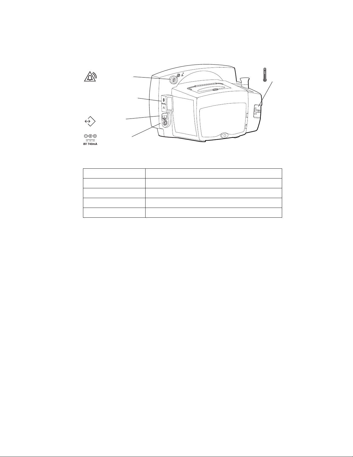
Connections
ax.
Nurse Call Cable
30V , 1A M
Connector
SpO
SpO2 Sensor Cable
2
Connector
RS232 Cable
Connector
DC Power Cable
Connector
For information on the connections, refer to the following:
AC Power Adapter “Connecting AC Power” on page 11
Temperature Probe “Connecting the Temperature Probe Cable” on page 14
Sensor “Connecting and Disconnecting the SpO2 Sensor Cable” on page 15
SpO
2
NIBP Cuff Hose “Connecting the NIBP Cuff Hose” on page 13
Nurse Call Cable “Nurse Call” on page 81
Temperature Probe
Cable Connector
Page 17

11
2
Setup
This chapter describes the set-up procedures for patient monitoring.
Connections
Use the procedures described below to connect components to the monitor.
Connecting AC Power
The monitor operates on DC power, supplied by either the internal battery or the AC
power adapter. (For information on the battery, refer to “Battery Operation” on page 71
and “Electrical” on page 76.)
When the AC power adapter is connected, it simultaneously powers the monitor and
charges the internal battery. When the AC power adapter is not connected, the monitor
operates on the internal battery.
Caution Use only the medical-grade AC power adapter approved by Welch Allyn.
(Refer to the Welch Allyn Parts and Accessories Guide (810-0409-XX) for ordering
information.) Using an unqualified power adapter can have the following results:
• violation of isolation requirements
• hazard to the patient
• damage to the monitor
• nullification of the product warranty
Page 18
12 Chapter 2 Setup Welch Allyn Vital Signs Monitor 300 Series
To use the AC power adapter:
1. Plug the power adapter into the AC power source.
2. Plug the power adapter connector into the monitor DC port.
AC Power
Adapter Port
Use the AC power adapter to fully charge the battery before using the monitor. (This can
take up to 12 hours.)
Caution Fully charge the battery before using the monitor for the first time.
Failure to do so will result in poor battery performance and reduced battery life.
• While the monitor is charging, the AC/charging indicator flashes.
• When the monitor is 90% charged, the AC/charging indicator is steady. To fully
charge the battery, leave the AC power adapter connected for a few more hours.
• After the monitor is fully charged for the first time, the monitor can be powered by the
AC power adapter or by the internal battery.
Page 19
Directions for Use Chapter 2 Setup 13
Connecting the NIBP Cuff Hose
Attach the hose to the monitor and the cuff as follows, referring to the illustration below:
1. Screw the hose connector onto the NIBP connector on the monitor.
2. Connect the monitor hose connector to the mating connector on the cuff.
Threaded NIBP
Hose Connector
For information on NIBP measurements, see “Patient Monitoring” on page 31.
Page 20
14 Chapter 2 Setup Welch Allyn Vital Signs Monitor 300 Series
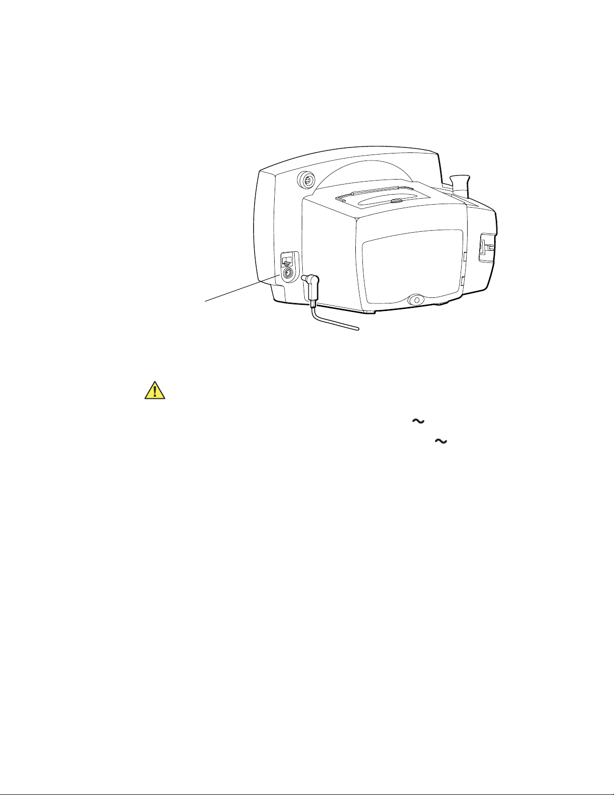
Connecting the Temperature Probe Cable
Follow these steps to connect the temperature probe cable to the monitor.
1. Locate the temperature probe connector port on the back of the monitor.
2. Holding the temperature probe cable connector with the spring tab on the right,
carefully insert it into the monitor temperature probe connector port. The spring tab
clicks out when the connector halves are fully and correctly mated.
3. To disconnect the temperature probe cable, depress the spring tab and withdraw the
cable connector.
Temperature Probe
Connector Port
Temperature Probe Cable
Connector
For information on temperature measurements, see “Patient Monitoring” on page 31.
Page 21
Directions for Use Chapter 2 Setup 15
Connecting and Disconnecting the SpO2 Sensor Cable
To connect the SpO2 sensor cable:
1. Locate the SpO
2. Note the hole patterns of the connector halves, and align the cable connector
accordingly.
3. Carefully insert the SpO
If you are using a sensor extension cable, plug the sensor into the extension cable and
plug the extension cable into the monitor.
sensor cable connector (labeled SpO2) on the side of the monitor.
2
cable connector into the SpO2 monitor connector.
2
Page 22
16 Chapter 2 Setup Welch Allyn Vital Signs Monitor 300 Series
To disconnect the SpO2 cable, refer to the instructions shown in the illustration below.
Note
Thumb and forefinger squeeze the tabs
in the shoulder of the connector cable
to release the cable connector.
For information on SpO
Always grasp the cable by the connector shoulder. Do not pull on the cable itself.
measurements, see “Patient Monitoring” on page 31.
2
Page 23

Directions for Use Chapter 2 Setup 17
ºF
ºF
ºC
M
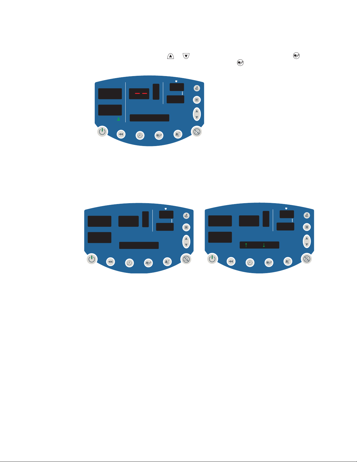
Power On, Power-on Self-Test, and Power Off
When the battery is charged, press to turn on the monitor.
The monitor runs a diagnostic self-test each time it powers up.
• If all tested functions are working normally, the various windows briefly display
start-up values (‘8’ and ‘--’) and a short tone sounds twice.
mmHg
SYS
8.8.8.
DIA
kPa
SpO2 %
/min
SYS
SpO2 %
18.8.
DIA
/min
8.8.8.
****************
SYS
DIA
SpO2 %
/min
8.8.8.
1.8.8.8.
ºF
ºC
12
34
mmHg
****************
SYS
0
DIA
SpO2 %
/min
0
ºF
0
****************
• If the self-test fails, an error code appears in the SYS window.
When the self-test is complete, the software version appears briefly in the message
window, followed by the current time of day.
00:00:45
Caution Always observe the monitor during power-up. If any display fails to
illuminate properly, or if an error code appears in the systolic window, inform your
biomedical engineering department immediately, or call your nearest Welch Allyn
Customer Service or Technical Support facility. Do not use the monitor until the
problem is corrected.
To shut off the monitor, press .
Note
Shutting off the monitor erases all stored patient data but does not erase settings
or configuration parameters.
Page 24
18 Chapter 2 Setup Welch Allyn Vital Signs Monitor 300 Series
ºF
M
Configuring Operating Parameters
You can change several monitor operating parameters. When changed, these settings
become the default power-up settings.
How to Use the Menu System
The monitor menu system contains three sets of menus—settings, configuration, and
service.
Settings Menu
Access the settings menu by pressing the menu button while in normal operation.
Then press repeatedly to reach the setting of interest.
Settings Menu
128
71
98
54
37.0
MAP 90mmHg
Power Off - all values saved
except target inflation pressure
No action for 10 seconds
or
Press any button other than
Patient Type
Target Cuff Inflation Pressure
Temperature Units
Temperature Type
ºF
ºCºCM
Pulse Tone Volume
Page 25

Directions for Use Chapter 2 Setup 19
ºF
M
ºC
M
Use the settings menu to select and set the following parameters:
Patient Type Neonate Term birth through 28 days, or up to 44 gestational weeks
Pediatric 29 days through 12 years
Adult 13 years and older
Target Pressure The initial cuff inflation pressure (set individually for each patient type)
Temp Modes Fahrenheit Predictive
ºF
Fahrenheit Monitored
ºFºFM
Celsius Predictive
ºC
Celsius Monitored
ºCºCM
Pulse Tone Volume From 0 (silent) to 5 (loudest)
To change a settings parameter:
1. Select the parameter as indicated above.
2. Change the value by pressing or .
3. Set the displayed new value either by doing nothing for 10 seconds or by pressing any
button other than or . If you press a function button (such as ), the monitor
returns to normal operation with that function ( ) activated.
Page 26
20 Chapter 2 Setup Welch Allyn Vital Signs Monitor 300 Series
Confi
Configuration Menu
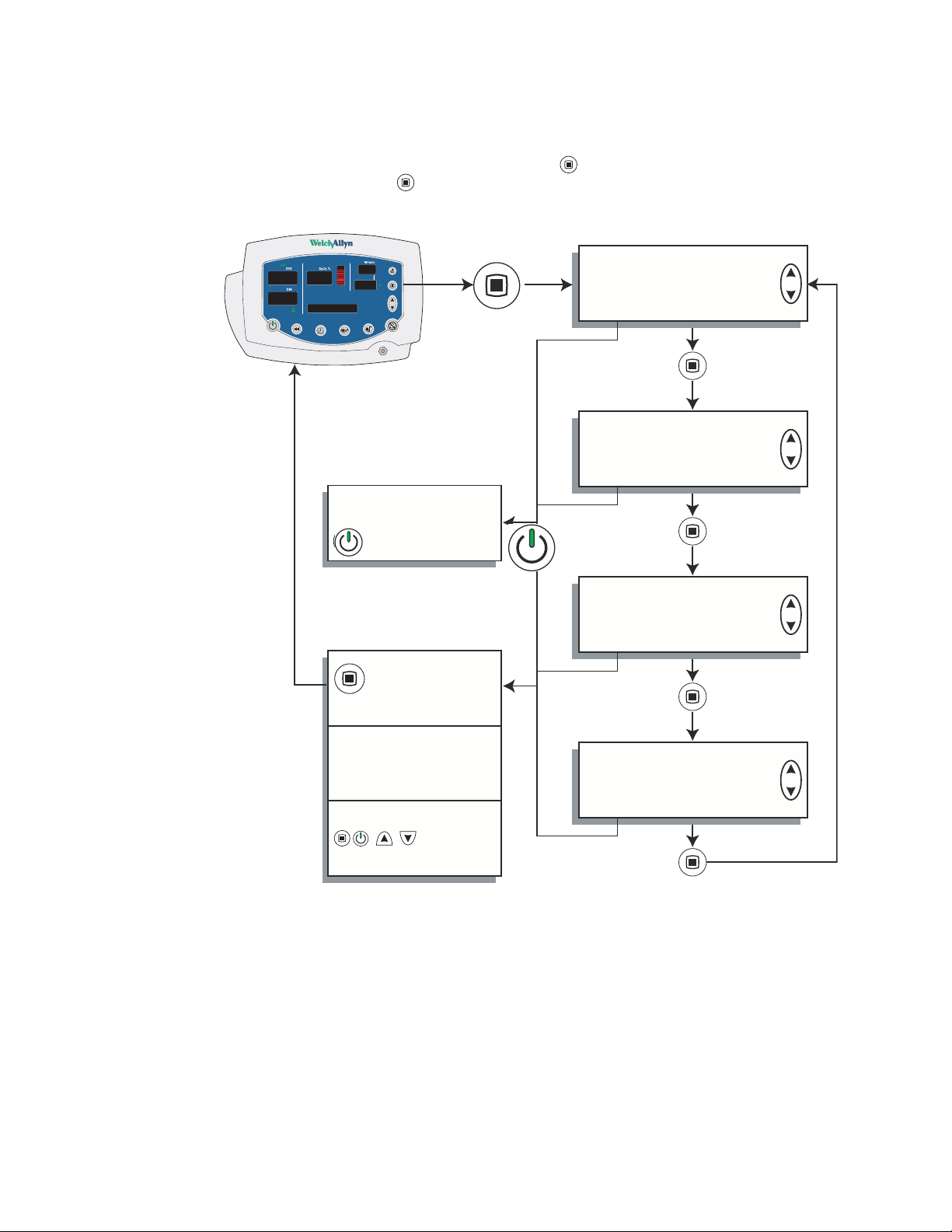
The configuration menu is accessed by pressing and keeping it depressed for three
seconds. You then press repeatedly until you reach the setting of interest.
guration Menu
128
71
98
MAP 90 kPa
54
37.0
Press and hold
Power Off - all values saved
Press and hold for 3
seconds
Set Time and Date
for 3 seconds
MAP
Enable
Disable
NIBP Units
mmHg
kPa
No action for 10 seconds
Press any button other than
Print
Stream
Batch
Page 27

Directions for Use Chapter 2 Setup 21
Use the configuration menu to select and set the following parameters:
Time and Date hour
minute
year
month
day
MAP Measurement Enabled
Blood Pressure
Measurement Units
Print Mode Batch
Disabled
mmHg (millimeters of mercury)
kPa (kilopascals)
Stream
To change a configuration parameter:
1. Select the parameter as indicated above.
2. Change the value by pressing or .
3. Set the displayed new value either by doing nothing for 10 seconds or by pressing any
button other than or . If you press a function button (such as ), the monitor
returns to normal operation with that function ( ) activated.
Page 28
22 Chapter 2 Setup Welch Allyn Vital Signs Monitor 300 Series
ºF
Changing the Time and Date
Follow these steps to change the time and date settings of the monitor internal clock.
1. Press and hold for 3 seconds. SET HOUR XX appears in the message window.
mmHg
SYS
SpO2 %
DIA
SET HOUR 00
/min
ºF
2. Press or as needed to change XX to the current hour.
3. Press once to set the hours and change the display to SET MINUTE XX.
4. Press or as needed to change XX to the current minute.
5. Press once set the minutes and to change the display to SET YEAR XX.
6. Press or as needed to change XX to the current year.
7. Press once to set the year and change the display to SET MONTH XXX.
8. Press or as needed to change XXX to the current month.
9. Press once to set the month and change the display to SET DAY XX.
10. Press or as needed to change XX to the current day.
Page 29
Directions for Use Chapter 2 Setup 23
ºF
11. To save the displayed time and date settings, either do nothing for 10 seconds or
press any button other than or . If you press a function button (such as ), the
monitor returns to normal operation with that function ( ) activated.
mmHg
SYS
DIA
SpO2 %
0
/min
0
ºF
0
09:24:17
You cannot change the date and time while memory contains stored vital-signs data. If
you attempt to change the date and time setting while data is stored, the question
ERASE DATA? appears in the message window. If you confirm the data erasure, the
monitor erases the data from memory and returns you to the date-set function. If you
select NO, the stored data is retained in memory and the monitor returns to normal
operation.
SYS
DIA
SpO2 %
ERASE DATA?
/min
SYS
SpO2 %
DIA
= YES = NO
/min
Page 30

24 Chapter 2 Setup Welch Allyn Vital Signs Monitor 300 Series
ºF
ºF
Changing the Patient Type
The age range for each patient type is defined as follows:
Neonatal Term birth through 28 days, or up to 44 gestational weeks
Pediatric 29 days through 12 years
Adult 13 years and older
Default setting: ADULT.
Follow these steps to change the patient type setting.
1. Press . The current patient type ( , , or ) appears below the DIA window, and
NEONATE, PEDIATRIC, or ADULT appears in the message window.
2. Press or to display , , or .
3. To select the displayed patient type and return to normal operation, either do nothing
for 10 seconds or press any button other than or . If you press a function button
(such as ), the monitor returns to normal operation with that function ( ) activated.
mmHg
SYS
DIA
0
SpO2 %
/min
0
mmHg
SYS
ºF
DIA
SpO2 %
/min
ºF
0
ADULT
Changing the patient type has the following effects:
• Alarm limits are reset to the default limits for the new patient type
• Cuff inflation target pressure is reset to the default for the new patient type
If you cycle through the patient types but do not change the setting, the alarm limits and
the cuff inflation target pressure settings do not change.
NEONATE
Page 31

Directions for Use Chapter 2 Setup 25
ºF
ºF
MAP Measurement Enable and Disable
Default setting: MAP ENABLED for neonate; MAP DISABLED for adult and pediatric.
1. Depress for 3 seconds. SET HOUR XX appears in the message window.
2. Press repeatedly until MAP ENABLED or MAP DISABLED appears in the display
window.
mmHg
SYS
SpO2 %
DIA
/min
ºF
MAP DISABLED
3. Press or to enable or disable MAP measurement.
Note
If you change the MAP enabled/disabled setting, refer to “How Changing the
Patient Type Affects MAP Defaults” on page 38.
4. To select the displayed state and return to normal operation, either do nothing for 10
seconds or press any button other than or . If you press a function button (such
as ), the monitor returns to normal operation with that function ( ) activated.
mmHg
SYS
SpO2 %
DIA
/min
ºF
MAP ENABLED
For information about MAP measurements, see “Patient Monitoring” on page 31.
Page 32

26 Chapter 2 Setup Welch Allyn Vital Signs Monitor 300 Series
ºF
ºF
Changing the NIBP Measurement Units
Default setting: mmHg.
To c h a ng e t h e N IB P measurement units:
1. Depress for 3 seconds. SET HOUR XX appears in the message window.
2. Press repeatedly until BP Units: mmHg or BP Units: kPa appears in the display
window.
mmHg
SYS
SpO2 %
DIA
/min
ºF
BP Units: mmHg
3. Press or as needed to display the desired NIBP measurement units.
4. To select the displayed units and return to normal operation, either do nothing for 10
seconds or press any button other than or . If you press a function button (such
as ), the monitor returns to normal operation with that function ( ) activated.
SYS
kPa
DIA
SpO2 %
BP Units: kPa
/min
ºF
For information on NIBP measurements, see “Patient Monitoring” on page 31.
Page 33

Directions for Use Chapter 2 Setup 27
ºC
M
ºF
Changing Temperature Type and Measurement Units
Default setting: F (Fahrenheit predictive).
To change the temperature type and the temperature measurement units:
1. With the monitor on, press repeatedly until TEMP MODE appears in the display
window. One or two green LEDs to the right of the temperature window illuminate to
indicate the selected temperature type.
mmHg
SYS
SpO2 %
DIA
TEMP MODE
/min
ºC
2. Press or as needed to cycle to the desired display:
F (Fahrenheit Predictive)
FM (Fahrenheit Monitored)
C (Celsius Predictive)
CM (Celsius Monitored)
98
/min
0
ºF
.6
mmHg
SYS
119
DIA
SpO2 %
79
20:30:16
3. To select the displayed units and return to normal operation, either do nothing for 10
seconds or press any button other than or . If you press a function button (such
as ), the monitor returns to normal operation with that function ( ) activated.
For information on temperature measurements, see “Patient Monitoring” on page 31.
Page 34

28 Chapter 2 Setup Welch Allyn Vital Signs Monitor 300 Series
ºC
M
ºC
M
Changing the Volume of the Pulse Tone
Default setting: 03.
The pulse tone can be set from level 00 (volume off) to level 05 (volume on full).
To adjust the volume of the SpO
pulse tone, do the following:
2
1. Press repeatedly until VOLUME XX appears in the display window and the pulse
tone sounds continuously.
SYS
kPa
DIA
SpO2 %
VOLUME 03
/min
ºC
2. Press or to raise or lower the volume level.
SYS
kPa
DIA
SpO2 %
VOLUME 05
/min
ºC
3. To set the displayed volume level and return to normal operation, either do nothing for
10 seconds or press any button other than or . If you press a function button
(such as ), the monitor returns to normal operation with that function ( ) activated.
Note
Changing the volume of the pulse tone has no effect on the volume of the alarm
tones.
Page 35

Directions for Use Chapter 2 Setup 29
ºC
M
ºC
M
Selecting Stream or Batch Printing
Default setting: BATCH.
For monitors configured with the optional thermal printer:
1. Press and hold for three seconds.
2. Press until the message window reads PRINT: BATCH or PRINT: STREAM.
SYS
kPa
DIA
SpO2 %
/min
ºC
PRINT: STREAM
3. Press or to alternate between PRINT: BATCH and PRINT: STREAM display.
4. To set the displayed printing method and return to normal operation, do nothing for 10
seconds or press any key other than or . If you press a function button (such as
), the monitor returns to normal operation with that function ( ) activated.
SYS
kPa
DIA
SpO2 %
PRINT: BATCH
/min
ºC
For information on using the printer, see “Patient Monitoring” on page 31.
Page 36

30 Chapter 2 Setup Welch Allyn Vital Signs Monitor 300 Series
Page 37

31
3
Patient Monitoring
Monitoring Blood Pressure
WARNING To ensure safe and accurate NIBP measurements, use only cuffs and
hoses approved by or supplied by Welch Allyn.
WARNING Never use an adult or pediatric monitor setting or cuff for an NIBP
measurement on a neonatal patient. Adult and pediatric inflation limits can be
excessive for neonatal patients, even if a neonatal cuff is used.
WARNING NIBP readings may be inaccurate for patients experiencing moderate
to severe arrhythmia.
WARNING When patients are being monitored frequently or monitored for a
prolonged period, regularly remove the cuff to inspect it and to inspect the
patient’s cuffed extremity for ischemia, purpura, or neuropathy.
WARNING To avoid the risk of intravenous line misconnection and possible
introduction of air into a patient’s blood, do not fit the NIBP system with Luer Lock
adapters.
WARNING Do not place the cuff on an extremity already being used for
intravenous infusions or SpO
monitoring.
2
WARNING Do not place the cuff where it can affect proper circulation.
WARNING NIBP measurements may be inaccurate in the presence of excessive
motion artifact.
Caution Pulse rate measurements generated through the blood pressure cuff or
through SpO2 are subject to artifact and might not be as accurate as heart rate
measurements generated through ECG or through manual palpation.
Page 38

32 Chapter 3 Patient Monitoring Welch Allyn Vital Signs Monitor 300 Series
NIBP Preparation
Before you start any NIBP measurement, always follow the steps described in these
procedures:
• “Changing the Target Pressure” on page 32
• “Selecting a Cuff” on page 32
• “Positioning the Cuff” on page 33
Changing the Target Pressure
Follow these steps to change the target pressure (default initial pressure for cuff inflation)
for the current patient type:
1. Press until the message window displays TARGET PRESSURE.
The SYS window displays the current setting for initial inflation pressure.
2. Press or to raise or lower the preset pressure value to the target level.
To set the displayed pressure level and return to normal operation, either do nothing
for 10 seconds or press any button other than or . If you press a function button
(such as ), the monitor returns to normal operation with that function ( ) activated.
Note
Selecting a Cuff
You can tell whether the cuff size is appropriate by putting the cuff on the patient and then
inspecting the fit. If the edge marking lies somewhere between the two range markings,
then the fit is correct.
You can also find the correct cuff by measuring the circumference of the patient’s arm at
the biceps:
Target pressure is a nominal starting point. If it is too low to take a measurement,
the monitor takes another measurement using a higher initial pressure.
Cuff Size Circumference
(inches)
Neonate #1 1.3 - 2.2 3.3 - 5.6 Small Child 4.9 - 6.6 12.4 - 16.8
Neonate #2 1.6 - 2.8 4.2 - 7.1 Child 6.2 - 8.4 15.8 - 21.3
Neonate #3 2.1 - 3.6 5.4 - 9.1 Small Adult 7.9 - 10.6 20.0 - 27.0
Neonate #4 2.4 - 4.6 6.9 - 11.7 Adult 10.0 - 13.5 25.3 - 34.4
Neonate #5 3.5 - 5.9 8.9 - 15.0 Large Adult 12.6 - 17.1 32.1 - 43.4
Infant 3.9 - 5.2 9.8 - 13.3 Thigh 16.0 - 21.7 40.7 - 55.0
Circumference
(centimeters)
Cuff Size Circumference
(inches)
Circumference
(centimeters)
Page 39

Directions for Use Chapter 3 Patient Monitoring 33
Positioning the Cuff
For the most accurate measurement, do the following:
1. Position the cuff on the bare arm, midway between the shoulder and the elbow.
Typical cuff positions are shown in this illustration:
Neonatal
Adult and Pediatric
2. Position the alignment mark on the cuff directly over the brachial artery.
Note
Be sure that the cuff is neither too tight nor too loose. When putting it on the
patient, wrap it so that you can comfortably fit two fingers between the cuff and
the arm.
Be sure that the air hose has no kinks or twists.
During an NIBP measurement, limit the movement of the cuff and the cuffed
extremity.
If the cuff is not level with the heart, add 1.8 mmHg to the displayed reading for
each inch of elevation above the heart, or subtract 1.8 mmHg from the displayed
reading for each inch of elevation below the heart.
Always use the appropriate cuff size for each patient.
Page 40

34 Chapter 3 Patient Monitoring Welch Allyn Vital Signs Monitor 300 Series
ºF
ºC
M
Manual NIBP Measurement
Follow these steps to take a single NIBP measurement.
1. Attach the cuff to the patient’s arm.
2. Press .
• The monitor inflates the cuff.
• The SYS window dynamically displays the current cuff pressure.
Note
If the message ‘CAL’ appears in the message window when you attempt to start
an NIBP cycle, it means that the NIBP measurement system is self-calibrating to
a zero baseline and is temporarily unavailable (for up to 30 seconds). The
requested NIBP cycle begins when the calibration is complete. However, the cuff
must remain stationary for at least 15 seconds for the calibration to complete.
mmHg
SYS
CAL
DIA
SpO2 %
20:30:28
/min
0
ºF
• When the NIBP cycle is completed, a tone sounds and the NIBP measurement
results are displayed in the SYS, DIA, and pulse rate windows.
mmHg
SYS
119
DIA
SpO2 %
/min
69
ºC
79
20:06:09
Page 41

Directions for Use Chapter 3 Patient Monitoring 35
ºC
M
• If MAP is enabled, MAP results are displayed in the message window.
Note
If the SpO
sensor is attached and generating valid pulse rate data, then the
2
displayed pulse rate is derived from the SpO
The measurement display persists for two minutes or until another NIBP cycle is
initiated. If an error is detected, an error tone sounds and an error code appears in
the SYS window.
Automatic NIBP Measurement
Automatic NIBP measurements repeat continuously at programmed intervals.
Note
To set up an automatic NIBP measurement, do the following:
1. Attach the cuff to the patient’s arm.
2. Press to set the measurement interval.
The interval is the time from the beginning of one measurement cycle to the
beginning of the next measurement cycle.
The two dashes (--) in the message window indicate that automatic measurement is
turned off.
mmHg
SYS
SpO2 %
/min
sensor reading.
2
DIA
INTERVAL --
ºC
3. To set an interval, press or to cycle through the options, which include - -, ST,
and a range of intervals: 1, 3, 4, 5, 10, 15, 30, 45, 60, 90, 120, and 240 minutes.
Note
The ST interval selection works differently from the other intervals. For
information on using these settings, please refer to “STAT Measurement” on
page 38.
Page 42

36 Chapter 3 Patient Monitoring Welch Allyn Vital Signs Monitor 300 Series
ºC
4. To select the currently displayed interval, press any button other than , or .
Ten seconds after you select an interval, and assuming that safe venous return
pressure (SVRP) has been maintained for at least 30 seconds, the monitor starts the
first automatic NIBP cycle and the following occurs:
• The cuff inflates to the default pressure level.
• The SYS window dynamically displays the current cuff pressure.
• If MAP is enabled, the MAP measurement value alternates with the time display
in the message window.
Note
If a MAP alarm occurs, the MAP is displayed steadily in the message window.
When the NIBP cycle ends, a tone sounds and the monitor displays the measurement
results, including pulse rate in the window. (If the SpO
the patient, the pulse rate is derived from the SpO
kPa
SYS
16.2
DIA
10
.
7
SpO2 %
20:05:42
/min
53
ºC
sensor.)
2
sensor is attached to
2
The measurement display persists until one of the following occurs:
• the next cycle begins, if the monitor is still in automatic NIBP mode
• two minutes pass
• is pressed again
Note
If the first cycle does not produce a measurement, the monitor retries the
measurement using a target pressure calculated from the results of the previous
cycle.
Page 43

Directions for Use Chapter 3 Patient Monitoring 37
ºC
The automatic NIBP cycles continue until one of the following occurs:
• The monitor reaches the 5-minute limit for a STAT measurement. (The current
cycle continues to completion, even if it goes beyond the 5-minute limit.)
• The monitor halts because is pressed.
• The monitor halts because of an alarm, alert, or error condition.
• The interval code is changed to ‘- -’.
If an error is detected during the measurement, an error tone sounds and an error code
appears in the SYS window.
Note
MAP Measurement
MAP is available for adult, pediatric, and neonatal patients. The monitor is set at the
factory to enable MAP display and alarm limit checking for neonatal patients, and to
disable those functions for adult and pediatric patients.
If MAP is enabled, the monitor displays MAP readings in the message window at the end
of NIBP measurements.
10.7 9 8
6.0
The latest NIBP measurement is displayed until one of the following occurs:
• the next NIBP cycle starts
• an alarm, alert, or error occurs
• the monitor shuts down
SYS
kPa
DIA
SpO2 %
MAP 7.5 kPa
/min
122
37.2
ºC
Page 44

38 Chapter 3 Patient Monitoring Welch Allyn Vital Signs Monitor 300 Series
How Changing the Patient Type Affects MAP Defaults
When you cycle power to the monitor, the monitor stores all current settings before
shutting down. It then uses these saved settings when it powers up again. (This does not
affect the factory default settings.)
Whenever you enable or disable MAP for a given patient type—Adult, Pediatric,
Neonatal—the current enabled/disabled setting becomes the default power-up setting for
that patient type.
For example: If the monitor is set to Neonatal and you set MAP Disabled, MAP Disabled
becomes the default setting for neonatal patients until you change the enabled/disabled
setting again.
Enabling and Disabling MAP Measurement
See “MAP Measurement Enable and Disable” on page 25.
STAT Measurement
If the selected interval is STAT, the monitor takes repeated NIBP measurements for 5
minutes, starting a new cycle each time the cuff deflates below safe venous return
pressure (SVRP) for two seconds.
Current cuff pressures are not dynamically displayed during a STAT reading. The message
window displays the NIBP reading from the previous cycle until the current cycle finishes.
(Before the first cycle finishes, the display reads ‘0.’)
Monitoring Pulse Rate
The monitor displays the pulse rate at the end of all NIBP or SpO2 measurements. It
displays NIBP pulse information only if no SpO
If the SpO
amplitude indicator rises and falls in rhythm with the monitored heart rate. The higher the
display rises, the stronger the measured pulse; however, the height of the indicator
display is not mathematically proportional to the volume of the pulse.
sensor is connected to the patient during the measurement period, the pulse
2
reading is available.
2
Page 45

Directions for Use Chapter 3 Patient Monitoring 39
Monitoring SpO
2
Warnings and Cautions — SpO
WARNING Disconnect the SpO2 cable from the monitor before defibrillating the
patient.
WARNING Always follow the manufacturer’s instructions for care and use of the
sensor.
SpO
2
WARNING The accuracy of the SpO
the following:
• the presence of significant amounts of dysfunctional hemoglobin, such as
carboxyhemoglobin or methemoglobin
• the presence of concentrations of some intravascular dyes, sufficient to
change the patient’s usual arterial pigmentation
• patient movement
• patient conditions such as shivering and smoke inhalation
• painted nails
• poor oxygen perfusion
• anemia or low concentrations of hemoglobin
• hypotension or hypertension
• severe vasoconstriction
• shock or cardiac arrest
• venous pulsations or sudden and significant changes in pulse rate
• proximity to an MRI environment
• moisture in the sensor
• excessive ambient light, especially fluorescent
• wrong sensor or sensor too tight
WARNING If there is any question of the accuracy of an SpO
verify the measurement using another clinically accepted measurement method.
2
measurement can be affected by any of
2
measurement,
2
Page 46

40 Chapter 3 Patient Monitoring Welch Allyn Vital Signs Monitor 300 Series
WARNING Do not use the SpO2 sensor as an apnea monitor.
WARNING During prolonged, continuous SpO
site often, in compliance with the sensor manufacturer’s directions. Inspect the
patient’s skin integrity and circulation, and relocate the sensor if necessary.
Tissue damage can result from improper or prolonged sensor attachment.
• Use only sensors and accessories recommended by Welch Allyn.
• Do not use damaged sensors or cables.
• Do not use a sensor with exposed optical components.
• Do not immerse or wet the sensor.
Caution Some sensors might not work with some patients. If, after 20 seconds,
a properly functioning sensor fails to discern a pulse, do the following:
1. Adjust or reposition the sensor. If the failure continues:
2. Use a different type of sensor.
SpO2 Monitoring Procedure
1. Verify that the SpO2 sensor cable is connected to the monitor.
2. Attach the SpO
below. The sensor can be attached to the patient when the monitor is on or off, and
during an NIBP cycle.
finger clip sensor to the end of the patient’s index finger, as shown
2
monitoring, check the sensor
2
WARNING Do not use an SpO2 finger clip sensor and a blood pressure cuff
simultaneously on the same limb. To do so will result in inaccurate pulse rate and
perfusion readings, and could cause erroneous pulse rate alarms.
Page 47

Directions for Use Chapter 3 Patient Monitoring 41
ºF
Within a few seconds, the pulse amplitude indicator reflects the rate and strength of
the pulse.
Within less than 20 seconds, the SpO
a numeric pulse rate value appears in .
kPa
SYS
SpO2 %
17.1 9 9
DIA
/min
60
ºF
9.5
20:23:48
Note
During an SpO
sensor. Otherwise, the pulse rate is derived from NIBP.
Detaching the sensor during an SpO
If alarms are set for SpO
10 seconds causes an alarm.
If SpO
is being measured continuously on a patient over an extended period,
2
change the location of the sensor at least every three hours or as indicated by
the directions supplied with the sensor.
measurement, the displayed pulse rate is derived from the SpO2
2
or pulse rate, a condition of no pulse for between 5 and
2
window displays the SpO2 measurement and
2
measurement triggers an alarm.
2
To adjust the volume of the SpO
To ne” on page 28.
pulse tone, see “Changing the Volume of the Pulse
2
Page 48

42 Chapter 3 Patient Monitoring Welch Allyn Vital Signs Monitor 300 Series
Monitoring Temperature
Warnings and Cautions — Temperature
WARNING To ensure patient safety and to obtain accurate and reliable
temperature results, read this section thoroughly before using the temperature
instrument.
WARNING Always put a single-use probe tip cover on the probe tip before
taking a temperature measurement. Failure to use a probe tip cover can cause
patient discomfort, patient cross-contamination, and erroneous temperature
readings.
WARNING Use only Welch Allyn single-use disposable probe covers. The use of
any other probe cover can cause patient cross-contamination and erroneous
temperature readings.
WARNING Never re-use a probe cover.
WARNING Using a probe at the wrong site produces inaccurate measurements
and can cause patient injury.
• Use only oral probes, identified by a blue ejection button at the top of the
probe, to take oral and axillary temperatures.
• Use only rectal probes, identified by a red ejection button at the top of the
probe, to take rectal temperatures.
WARNING Use only the oral probe well with the oral probe, and use only the
rectal probe well with the rectal probe. Using the wrong probe well can result in
patient cross-contamination.
WARNING Always verify direct probe-cover-to-skin contact. Do not take an
axillary temperature through the patient’s clothing.
WARNING Use extreme caution when taking rectal temperatures on children.
Insert the probe tip only 3/8-inch (~1 cm) to avoid risk of bowel perforation.
WARNING The thermometer case is not waterproof. Do not immerse it in fluids
or drip fluids onto it.
WARNING The thermometer consists of high-quality precision parts. Protect it
from severe impact or shock. Do not use the thermometer if you notice any signs
of damage to the probe or the instrument. If the thermometer probe is dropped
or damaged, remove it from service and have it inspected by a qualified service
person.
WARNING Do not use the thermometer for any purpose other than those
described in this document. Doing so will invalidate the product warranty.
Page 49

Directions for Use Chapter 3 Patient Monitoring 43
ºF
ºC
ºF
M
M
ºC
Setting the Temperature Measurement Type
The monitor, if configured with the temperature option, can provide both predictive and
monitored temperature measurements.
A predictive measurement is a one-time measurement that takes only a few seconds. It
results in a single temperature reading which is displayed at the end of the brief
measurement period. The monitor sounds three short tones to indicate the end of a
predictive measurement.
A monitored measurement is a continuous temperature monitoring, used when the
situation prevents accurate predictive measurement. For oral and rectal measurements,
three minutes of monitoring is recommended. For axillary measurements, five minutes of
monitoring is recommended.
WARNING Do not exceed the recommended measurement periods of three
minutes for oral and rectal measurements and five minutes for axillary
measurements.
During a monitored measurement, the temperature is displayed dynamically throughout
the measurement period. Unlike a predictive measurement, the monitor does not indicate
the end of any elapsed time for a monitored measurement.
To select the temperature measurement type:
1. Press repeatedly until TEMP MODE appears in the display window.
2. Press or to cycle to the option you wish to select:
ºF
ºF
Fahrenheit predictive Celsius predictive
Fahrenheit monitored Celsius monitored
ºC
ºC
M
M
3. To set the temperature measurement type and return the monitor to normal
operation, do nothing for 10 seconds or press any button other than or . If you
press a function button (such as ), the monitor returns to normal operation with that
function ( ) activated.
Page 50

44 Chapter 3 Patient Monitoring Welch Allyn Vital Signs Monitor 300 Series
ºF
ºC
Loading a Probe Cover
1. Holding the probe handle with your thumb and two fingers on the indentations of the
probe handle, withdraw the probe from the probe well.
2. Insert the probe into a probe cover and press the probe handle down firmly. The
probe handle moves slightly to engage the probe cover.
Ejecting a Used Probe Cover
Do not touch the used probe cover.
1. Position the probe over an appropriate disposal receptacle.
2. While holding the probe securely, push the probe cover ejector button (blue or red) to
remove the probe cover into the disposal receptacle.
Predictive Temperature Measurement
Note
To set up for predictive temperatures, please refer to the procedure described in
“Changing Temperature Type and Measurement Units” on page 27.
To take a predictive temperature, follow these steps:
Verify that the temperature measurement type is set to predictive.
(The display is either or ; the letter ‘M’ is not illuminated.)
ºF
ºC
Page 51

Directions for Use Chapter 3 Patient Monitoring 45
Oral Predictive
When used correctly, the monitor produces an accurate oral temperature measurement in
less than 6 seconds.
Note
1. Remove the temperature probe from the probe well.
2. Load a new probe cover by inserting the probe into a probe cover and pressing the
3. Place the probe tip under the patient’s tongue, on either side of the mouth and deep
For oral temperatures, use only the oral probe (blue ejection button) and the blue
probe well.
The temperature probe runs a self-test, displaying 188.8 for a few seconds. When it is
ready for use, the temperature window clears, and then OrL appears in the
temperature window.
probe handle down firmly. The probe handle moves slightly to engage the probe
cover.
Caution Use only Welch Allyn probe covers. The use of any other probe cover, or
failing to use a probe cover, can produce measurement errors or inaccuracies.
in the rear sublingual pocket.
Sublingual pockets
4. Have the patient close his/her lips around the probe.
Caution If the patient bites the probe, the probe can be damaged.
Page 52

46 Chapter 3 Patient Monitoring Welch Allyn Vital Signs Monitor 300 Series
ºF
5. Hold the probe in place to assure continuous contact with the oral tissue until the
measurement is complete.
Rotating segments appear in the temperature window, indicating that the
measurement is in progress.
Note
The probe must remain in steady contact with the sublingual pocket throughout
the measurement period; otherwise, the monitor fails to accurately predict the
temperature.
During the measurement period, the temperature window displays a “walking box”—
a box with the sides illuminated sequentially. When the temperature prediction is
complete, the monitor sounds three short tones and displays the temperature
reading, which persists for one minute.
98
/min
0
ºF
.6
mmHg
SYS
119
DIA
SpO2 %
79
20:30:16
6. Eject the probe cover by pressing the ejection button; hygienically dispose of the
probe cover.
7. Return the probe to the probe well.
If the monitor cannot make a predicted measurement within 60 seconds, it switches
to monitored temperature measurement and continues to monitor the patient’s
temperature. (See “Monitored Temperature Measurement” on page 50.)
c
Caution Do not monitor temperature continuously for more than 5 minutes.
Note
A probe position error (P) indicates that the probe was moved after making tissue
contact. If a probe position error occurs during the temperature determination,
the temperature display alternates between the measured temperature and ‘P’.
WARNING If the probe becomes contaminated, follow the instructions under
“Thermometer and Probe Cleaning Procedure” on page 51.
Page 53

Directions for Use Chapter 3 Patient Monitoring 47
Axillary Predictive
When used correctly, the monitor produces an accurate axillary temperature
measurement in less than 15 seconds for adults and in less than 13 seconds for pediatric
patients.
Note
Use Axillary Pediatric (AP) measurements for patients up to 17 years old.
Use Axillary Adult (AA) measurements for patients 18 years old and older.
1. Remove the temperature probe from the probe holder.
2. Press or to change the display to AP or AA.
3. Load a new probe cover by inserting the probe into a probe cover and pressing the
Note
For axillary temperatures, use only the oral probe (blue ejection button) and the
blue probe well.
The temperature probe runs a self-test, displaying 188.8 for a few seconds. When it is
ready for use, the temperature window clears, and then OrL appears in the
temperature window.
probe handle down firmly. The probe handle moves slightly to engage the probe
cover.
Caution Use only Welch Allyn probe covers. The use of any other probe cover, or
failing to use a probe cover, can produce measurement errors or inaccuracies.
Be sure that nothing touches the probe tip before you place it in the axillary
measurement site.
4. Lift the patient’s arm to fully expose the axilla.
Note
Do not allow the probe tip to make contact with the patient until the probe is
placed in the measurement site. Any such contact can cause an inaccurate
reading.
Page 54

48 Chapter 3 Patient Monitoring Welch Allyn Vital Signs Monitor 300 Series
5. Place the probe tip as high as possible in the axilla, and then bring the patient’s arm
down to make maximum contact with the probe tip. Hold the patient’s arm in this
position, keeping the patient as still as possible, for the duration of the measurement.
Note
Be sure that the probe tip is fully covered by the axilla and the arm, and that it is
not touching any clothing. Do not attempt to take an axillary temperature reading
through the patient’s clothing.
During the measurement period, the temperature window displays a “walking box”—
a box with the sides illuminated sequentially. When the temperature prediction is
complete, the monitor briefly sounds a tone and displays the temperature reading,
which remains on the display for one minute.
6. Remove the probe from the patient’s axilla.
7. Eject the probe cover by pressing the ejection button; hygienically dispose of the
probe cover.
8. Return the probe to the probe well.
If the monitor cannot make a predicted measurement within 60 seconds, it switches
to making a monitored temperature measurement. (See “Monitored Temperature
Measurement” on page 50.)
c
Caution Do not monitor temperature continuously for more than 5 minutes.
Note
If a probe position error occurs during the temperature determination, the
temperature display alternates between the measured temperature and ‘P’.
WARNING If the probe becomes contaminated, follow the instructions under
“Thermometer and Probe Cleaning Procedure” on page 51.
Page 55

Directions for Use Chapter 3 Patient Monitoring 49
Rectal Predictive
When used correctly, the monitor produces an accurate rectal temperature measurement
in less than 13 seconds.
Note
1. Remove the temperature probe from the probe holder.
2. Load a probe cover onto the probe.
3. Apply a thin coat of water-based lubricant to the tip of the probe cover.
4. Separate the patient’s buttocks with one hand.
5. Insert the probe tip 1
For rectal temperatures, use only the rectal probe (red ejection button) and the
red probe well.
The temperature probe runs a self-test, displaying ‘188.8’ for a few seconds. When it
is ready for use, a double tone sounds, the temperature window clears, and then rEC
appears in the message window.
.5 centimeter (5/8-inch) inside the rectal sphincter. Tilt the probe
slightly to ensure good tissue contact, and keep the buttocks separated throughout
the duration of the measurement.
WARNING Use extreme care to avoid any risk of bowel perforation.
During the measurement period, the temperature window displays a “walking box”—
a box with the sides illuminated sequentially. When the measurement is complete,
the monitor sounds a tone and displays the measurement in the temperature
window.
The monitor displays the temperature reading for one minute.
Note
6. Remove the probe.
7. Eject the probe cover by pressing the ejection button, and hygienically dispose of it.
8. Return the probe to the probe well.
If a probe position error occurs during the temperature determination, the
temperature display alternates between the measured temperature and ‘P’.
WARNING If the probe becomes contaminated, follow the instructions under
“Thermometer and Probe Cleaning Procedure” on page 51.
Page 56

50 Chapter 3 Patient Monitoring Welch Allyn Vital Signs Monitor 300 Series
M
ºF
ºC
ºC
M
Monitored Temperature Measurement
c
Caution Do not monitor temperature continuously for more than 5 minutes.
Note
Verify that the temperature measurement type is set to monitored. (The letter
, to the right of the temperature display window and below or , is
M
ºF
ºC
illuminated.)
The procedures for monitored and predictive temperature measurements are the same,
with the following exceptions:
For monitored measurements:
• The monitor must be set to take a monitored temperature. (See “Changing
Temperature Type and Measurement Units” on page 27.)
• The monitor displays the temperature continuously.
• The measurement continues until the probe is replaced in the probe holder.
SYS
14.6
DIA
kPa
SpO2 %
/min
84
36.9
ºC
8.9
20:27:50
Page 57

Directions for Use Chapter 3 Patient Monitoring 51
Thermometer and Probe Cleaning Procedure
1. Wipe the thermometer regularly with a cloth dampened with warm water and a mild
detergent solution.
2. Occasionally clean the thermometer and probe as necessary with either a 70%
isopropyl alcohol or a 10% solution of chlorine bleach.
Caution Do not immerse or soak the thermometer or probe in any type of fluid.
Caution Do not use steam, heat, or gas sterilization on the thermometer or
probe.
Caution Do not autoclave the thermometer or probe.
Removable Probe Well Cleaning Procedure
1. Remove the probe from the probe well, remove the probe well from the monitor, and
unplug the thermometer cable connector from the monitor.
2. Clean the inner and outer surfaces of the probe well by swabbing with a cloth
dampened with 70% isopropyl alcohol or a 10% solution of chlorine bleach. The probe
well can be immersed during cleaning.
Caution Do not use hard, sharp, or abrasive objects to clean the probe well.
Caution Do not use steam, heat, or gas sterilization on the probe well.
Caution Do not autoclave the probe well.
3. Thoroughly dry all surfaces.
4. Reassemble the thermometer components.
5. Reconnect the thermometer cable to the monitor, making sure it clicks into place.
6. Reinstall the probe well into the monitor.
7. Insert the probe into the probe well.
Note
You can replace any components of the thermometer, including the probe well.
Use only Welch Allyn parts, as listed in the Parts and Accessories Guide.
Page 58

52 Chapter 3 Patient Monitoring Welch Allyn Vital Signs Monitor 300 Series
Page 59

53
4
Alarms and Alerts
WARNING If you turn off any alarm limits while responding to an alarm, verify
alarm limits before you resume patient monitoring.
Responding to a Patient Alarm
WARNING If a patient alarm and an equipment alert occur at the same time,
take care of the patient alarm first.
A patient alarm occurs when a vital-sign measurement falls outside of programmed limits.
During a patient alarm, the monitor sounds the alarm tone—a repeating series of
intermittent short tones—and flashes the associated numerics in the appropriate window.
The alarm also activates the Nurse Call relay if the Nurse Call cable is connected.
Respond as follows:
1. Press to immediately silence the alarm tone.
•For SpO
condition has not been corrected.
• For NIBP-related alarms, the alarm is reset.
• For MAP-related alarms, the MAP measurement readings are displayed in
flashing text on the message display.
-related alarms, the alarm resumes 90 seconds later if the alarm
2
2. Check the patient and provide appropriate care.
Page 60

54 Chapter 4 Alarms and Alerts Welch Allyn Vital Signs Monitor 300 Series
Responding to an Equipment Alert
WARNING If a patient alarm and an equipment alert occur at the same time,
take care of the patient alarm first.
Recoverable Temperature, NIBP, or SpO2 Alert—Not Escalated
Most recoverable equipment alerts are not escalated to the level of patient alarms. When
an unescalated alert occurs, take the necessary steps to correct the equipment problem
and then resume patient monitoring.
For an unescalated equipment alert for Temperature, NIBP, or SpO
following:
• Beeps once
• Displays an error code (Cxx) in the relevant window—Temp, SYS, DIA, or SpO
Recoverable SpO2 Alert—Escalated
An SpO2 equipment alert is always escalated immediately to the level of a patient alarm if
it occurs when both of the following conditions exist:
•SpO
•An SpO
See “Responding to a Patient Alarm” on page 53.
monitoring has begun and the monitor has recorded an SpO2
2
measurement
or Pulse Rate alarm limit has been set
2
Recoverable NIBP Alert—Escalated
An NIBP equipment alert is escalated to the level of a patient alarm whenever both of the
following conditions exist:
• Two consecutive NIBP equipment alerts occur while the monitor is taking
automatic NIBP/PR measurements
• Alarms are enabled
, the monitor does the
2
2
See “Responding to a Patient Alarm” on page 53.
Note
For information about a battery alert, see “Battery Low Warning” on page 71
and “Battery Failure” on page 71.
Page 61

Directions for Use Chapter 4 Alarms and Alerts 55
Nonrecoverable Alerts
When the monitor detects a nonrecoverable equipment problem, it does the following
• Displays an error code in the SYS window, and shuts off the display to all other
windows
• Stops patient monitoring
• Stops the pump and opens the air valve
• Activates the Nurse Call relay (if connected)
• Produces an audible tone
• Shuts down as soon as is pressed or one minute has elapsed
Response
For both recoverable and nonrecoverable equipment alerts, respond as follows:
1. Press to immediately silence the alert tone.
2. Determine what caused the alert and correct the problem.
Page 62

56 Chapter 4 Alarms and Alerts Welch Allyn Vital Signs Monitor 300 Series
Alarm Indicators
The monitor alarm indicators are as follows:
Event Audible Indicator Visual Indicator
Patient Alarm Three short tones in quick succession, followed
by a short silence, and then two short tones in
quick succession, followed by a long silence;
repeated until action is taken.
Equipment Alert,
Nonrecoverable
Error Two short tones Continuous display of the error code in the
Equipment Alert,
Recoverable, NIBP
Equipment Alert,
Recoverable, SpO
after valid reading
Three short tones in quick succession, followed
by a short silence, and then two short tones in
quick succession, followed by a long silence;
repeated for one minute or until power is shut
off.
Two short tones Continuous display of the error code in the
Two short tones Flashing display of the last SpO
,
2
Flashing display of the violating value.
For a MAP violation, the monitor
repeatedly flashes the MAP numerics in
the message display.
Flashing display of the violating value for
one minute or until power is shut off.
appropriate window.
appropriate window.
and Pulse
Rate, followed in some cases by a Patient
Alarm tone.
2
Setting Alarms
During patient monitoring, an alarm occurs when a measurement falls outside the
programmed alarm limit. Alarms can be set or turned off for the following vital signs:
• Systolic high and systolic low
• Diastolic high and diastolic low
• Pulse rate high and pulse rate low
•SpO
• MAP high and MAP low
high and SpO2 low
2
Page 63

Directions for Use Chapter 4 Alarms and Alerts 57
Note
For patient safety, all alarms are reset to the factory default levels whenever the
patient type is changed. This means that you must either accept the default
alarm limits or set new limits every time you change patient type ( , , or ).
The ‘high’ alarm for any vital sign is always higher than the ‘low’ alarm for the
same vital sign. For example, the alarm limit for systolic high is always higher
than the alarm limit for systolic low.
A reading that exactly reaches the alarm threshold without crossing the alarm
threshold does not qualify as an alarm condition.
Set alarms for systolic and diastolic blood pressure, pulse rate, and SpO2 as follows:
1. P r e s s .
• All display windows are blanked, other than the message window and the SYS
window.
• The message window displays HIGH ALARM.
• The SYS window displays the current alarm setting for the upper limit of systolic
blood pressure. This setting is a numeric blood pressure level or it is ‘- -’,
indicating that no alarm is set for the selected vital sign.
2. For the selected vital sign, do one of the following:
• Leave the limit unchanged or
• Press or as needed to change the limit to another value or to ‘- -’ to disable
the alarm.
3. Press to accept the displayed alarm limit and advance to the next vital sign.
The display moves to the next window (for example, from SYS HIGH to SYS LOW, or
from SYS LOW to DIA HIGH).
4. To continue changing alarm limits, repeat from step 2; to return to normal operation,
do nothing for 10 seconds.
To set the MAP alarm limits, if MAP is enabled:
5. Continue from (step 3) until you have cycled through all of the display windows; that
is, until you have cycled through SpO2 LOW.
The display moves to the message window, which displays the current MAP high
alarm limit, as follows:
MAP ↑ XXX mmHg or MAP ↑ XXX kPa
MAP ↓ XXX mmHg or MAP ↓ XXX kPa
Page 64

58 Chapter 4 Alarms and Alerts Welch Allyn Vital Signs Monitor 300 Series
6. Change or accept the MAP high alarm limit as described above (from step 2).
7. Press to step to the MAP low alarm limit.
8. Change or accept the MAP low alarm limit.
The range of high and low alarm limits for each vital sign is shown here:
Alarm Limits for Vital Signs
Vital Sign Low Limit (Default) High Limit (Default) Resolution
Systolic (mmHg)
Neonatal 30 - 110 (50) 35 - 115 (100) 5 mmHg (0.5 kPa)
Pediatric 35 - 150 (75) 40 - 155 (145) 5 mmHg (0.5 kPa)
Adult 35 - 250 (75) 40 - 255 (220) 5 mmHg (0.5 kPa)
Diastolic (mmHg)
Neonatal 15 - 95 (30) 20 - 100 (70) 5 mmHg (0.5 kPa)
Pediatric 20 - 120 (35) 25 - 125 (100) 5 mmHg (0.5 kPa)
Adult 25 - 225 (35) 30 - 230 (110) 5 mmHg (0.5 kPa)
Mean Arterial Pressure (mmHg)
Neonatal 15 - 100 (35) 20 - 105 (80) 5 mmHg (0.5 kPa)
Pediatric 20 - 130 (50) 25 - 135 (110) 5 mmHg (0.5 kPa)
Adult 25 - 245 (50) 30 - 250 (120) 5 mmHg (0.5 kPa)
Pulse Rate (beats per minute)
Neonatal 35 - 210 (100) 40 - 215 (200) 5 bpm
Pediatric 35- 210 (50) 40 - 215 (150) 5 bpm
Adult 35 - 210 (50) 40 - 215 (120) 5 bpm
(%)
SpO
2
Neonatal 50 - 98 (85) 51 - 99 (95) 1%
Pediatric 50 - 98 (85) 51 - 99 (---) 1%
Adult 50 - 98 (85) 51 - 99 (---) 1%
Page 65

Directions for Use Chapter 4 Alarms and Alerts 59
Nurse Call
The monitor can be connected to a Nurse Call system through a customized cable that
connects to the Nurse Call connector. When the cable is connected and operational, the
monitor immediately notifies the Nurse Call system when a patient alarm occurs.
Nurse Call Cable
Connector
To connect the monitor to a Nurse Call system, you must have a cable (Welch Allyn part
number 008-0634-XX or equivalent) that has been adapted to your Nurse Call system. This
cable can be built or customized by a biomedical engineering department or other
appropriate technical resource, using the specification described on “Nurse Call” on
page 81.
WARNING Although the Nurse Call option enables remote notification of an
alarm condition, it is not intended to replace appropriate bedside patient
surveillance by trained clinicians.
Note
When a patient alarm occurs, pressing silences the monitor alarm tone and
the Nurse Call alarm for 90 seconds, but does not suspend the visual alarm
indicator on the monitor.
Page 66

60 Chapter 4 Alarms and Alerts Welch Allyn Vital Signs Monitor 300 Series
Error Codes
Error
Code
Description
Blood Pressure
C01 NIBP cycle cancelled by operator.
C02 Unable to calibrate. Either the cuff is being moved excessively during the calibration or
the NIBP unit is not working.
C03 Inflation too rapid. Check for hose constriction. Verify patient type setting.
C04 Inflation too slow. Check for hose leak. Verify patient type setting.
C05 Excessive noise or air leak. Check patient condition, cuff placement and connection. Limit
patient motion.
C06 Pressure measurement outside monitor range.
C10 Cuff pressure was too high. Check the patient’s condition.
SpO
2
-- Sensor problem. Check patient condition and sensor position/contact.
Verify SpO
C7 The sensor is broken, missing, or incompatible. Contact customer service.
C20 The probe is broken or missing or the probe well is missing. Contact customer service.
P The temperature probe has poor tissue contact.
C13 Battery failure. Use the AC power adapter.
and pulse rate using an alternative method.
2
Temperature
General
E20-E50 Internal failure. Contact customer service.
Page 67

61
5
Reviewing Patient Data
You can review stored patient data either by viewing it on the monitor or by printing it.
Displaying Stored Patient Data
1. Press to display the most recent stored set of patient vital-signs data.
• The monitor interrupts the dynamic display of any current vital-sign
measurement.
• The message READING appears in the message window, with a data-set
sequence number and the time of the displayed reading. (During a patient data
review, if MAP is enabled, this display alternates every two seconds with the
MAP display.)
2. Press or to cycle through the stored measurement data sets. (The monitor
stores 99 measurement cycles.)
3. To return to normal operation, press any button other than or . If you press a
function button (such as ), the monitor returns to normal operation with that
function ( ) activated.
Printing Patient Data
Note
The printer provides a way to view and save patient vital-signs data. It can be configured
to print all stored data as a single batch or to print a continuing stream of data as the data
is recorded in memory. (See “Selecting Stream or Batch Printing” on page 29.)
The information in this section pertains only to monitors configured with the
optional thermal printer.
Page 68

62 Chapter 5 Reviewing Patient Data Welch Allyn Vital Signs Monitor 300 Series
To Start and Stop Printing
• If the monitor is not printing, press to start printing.
• If the monitor is printing, press to stop printing. (If the monitor is set to Stream
printing, the printer prints a footer before stopping.)
Note
Batch Printing
After a patient has been continuously monitored over some period, a clinician can use the
monitor’s batch printing capability to print all of the measurements that were stored in
the monitor’s memory over the monitoring period.
When the monitor is configured for batch printing, and while it is in normal operating
mode, press to print all readings stored in memory (up to 99 cycles), starting with the
oldest measurement cycle and working forward. The message PRINTING is displayed
during the batch print, and all monitor controls other than and are disabled. Batch
printing continues until one of the following occurs:
In any of these cases, printing stops immediately.
Note
The print button is not enabled during an NIBP cycle or during a nonrecoverable
equipment alert.
• All stored data has been printed.
• is pressed again.
• A battery failure condition.
• A nonrecoverable error condition is detected.
If the monitor is configured for Stream printing but printing is disabled, you can
press and hold for 3 seconds to immediately start a Batch print job. When this
Batch job ends, the monitor is still configured for Stream printing.
Stream Printing
Alternatively, a clinician can choose to print a continuous stream of vital signs, where the
measurement information is printed as soon as the results of each cycle are recorded.
When the monitor is configured for stream printing, and while it is in normal operating
mode, press to immediately begin stream printing. Stream printing continues until one
of the following occurs:
Page 69

Directions for Use Chapter 5 Reviewing Patient Data 63
• is pressed again; the monitor prints an error log (if any errors occurred) and a
footer, and then printing stops.
• A nonrecoverable error condition is detected; printing stops immediately.
• A battery failure condition is detected. Printing is suspended as long as the
battery failure continues; if the AC power adapter is connected before the monitor
shuts down, printing resumes.
Printer Output
The printer standard report consists of a header, patient information, patient data (table
heading, date, time, range and alarm flags, and measurement readings), an error legend
and a footer. If the monitor receives a print request and no data is available, it prints only
the header and footer.
Header
| (R) |
| Vital Signs Monitor |
||
Patient Information
| Patient Name:___________________ |
| Patient ID:_____________________ |
| Physician:______________________ |
| Procedure:______________________ |
| Comments:_______________________ |
| ________________________________ |
| ________________________________ |
||
Patient Data
The contents of the Patient Data block reflect the configuration of the monitor; that is,
with or without the SpO
For a single cycle, all data except temperature is printed on one line; the temperature
data, if it exists, is printed on a second line. If the data for a single parameter is not
available, nothing is printed in the space provided for that parameter.
Welch Allyn
option and with or without the temperature option.
2
The patient data is displayed in a table consisting of a table heading, the current date, and
rows of patient vital-sign data.
Page 70

64 Chapter 5 Reviewing Patient Data Welch Allyn Vital Signs Monitor 300 Series
Table Heading
The Table Heading contains some or all of the following column headings (depending on
monitor configuration):
| Time Sys Dia MAP PR SpO2 |
| ---- mmHg ---- BPM % |
| --------------------------------- |
or
| Time Sys Dia MAP PR SpO2 |
| ---- kPa ---- BPM % |
| --------------------------------- |
or
| Time Sys Dia MAP PR |
| ---- kPa ---- BPM % |
| --------------------------------- |
or
| Time Sys Dia MAP PR |
| ---- mmHg ---- BPM % |
| --------------------------------- |
Date
Time
| DD-MMM-YYYY |
The recording time is printed for each record, in the form hh:mm (using a 24-hour clock),
at the beginning of the first line of the record.
In the illustration below, the first record (21:45) contains systolic and diastolic pressure,
MAP, pulse rate, and SpO2 readings; the second record (21:52) contains systolic and
diastolic pressure, MAP, pulse rate, and temperature; and the third record (22:12) contains
only a temperature reading. When temperature is the only recorded vital sign, the time is
printed on the same row as the temperature reading.
| Time Sys Dia MAP PR SpO2 |
| ---- mmHg ---- BPM % |
| --------------------------------- |
| 21:45 125 69
| 21:52 125 69↓ 90 72 98 |
| Temp 99.2F NOR/ORL |
| 22:12 Temp 110.0F
↓ 90 72 98 |
↑ NOR/ORL |
Page 71

Directions for Use Chapter 5 Reviewing Patient Data 65
Range and Alarm Flags
Flag characters (↑ and ↓) indicate a data value that falls outside of a defined range or
violates a programmed alarm threshold. In the illustration above, 69↓ indicates a diastolic
pressure value below the programmed alarm limit, and 110.0F↑ indicates a temperature
value above the monitor’s temperature measurement limit.
Temperature
The temperature notation includes information about the type and location of the
measurement, and can include error notation:
Ty pe
F Fahrenheit C Celsius
NOR Normal (predictive) MON Monitored
Location
OrL Oral (Oral probe)
AP Axillary Pediatric (Oral probe)
AA Axillary Adult (Oral probe)
Pulse Rate
SpO
2
rEC Rectal (Rectal probe)
Error
(P) Discontinuity in tissue contact during the measurement
period. The displayed temperature measurement is not
necessarily accurate.
C20 Broken or missing temperature probe.
The pulse rate notation does not include error information.
SpO2 notation can include error information:
C7 Malfunctioning sensor.
-- Sensor error.
Page 72

66 Chapter 5 Reviewing Patient Data Welch Allyn Vital Signs Monitor 300 Series
NIBP
NIBP notation can include error information:
C01 NIBP cycle cancelled by operator.
C02 Unable to calibrate.
C03 Cuff inflation to rapid.
C04 Excessive cuff inflation time.
C05 Excessive noise or air leak.
C06 Measurement out of range.
C10 Cuff overpressure.
Error Legend
If any error indicators appear in the printed data, the monitor prints an error legend. The
error legend contains a two-line header followed by a brief explanation of each error type
encountered in the data. The illustration below shows the error legend for a batch of data
containing at least one temperature (P) error, at least one NIBP C04 error, and no other
errors.
Footer
| Error Codes: |
| ------------ |
| (P) Loss of tissue contact |
| C04 Excessive inflation time |
||
The printout footer consists of a line containing the monitor serial number, a line
containing the monitor software version, two separator lines, and four blank lines:
| Unit S/N: JA736455 |
| S/W Ver.: 1.00.00 00005 |
| -------------------------------- |
| -------------------------------- |
||
||
||
||
Page 73

Directions for Use Chapter 5 Reviewing Patient Data 67
Erasing Patient Data
All patient vital-sign data is erased when the monitor is powered off or when you change
the time and date settings. You can also erase data at any time during normal monitor
operation.
Erasing Data Before Changing the Date and Time
If you attempt to change the date and time, the monitor prompts you to confirm that you
also want to erase all stored patient data.
Note
To erase patient data, press ; the monitor erases the data and enables the date/time
adjustment. (For information on changing the time and date settings, see “Changing the
Time and Date” on page 22.)
You cannot change the date and time without also erasing all stored patient data.
Erasing Data During Normal Operation
To erase patient data during normal operation, press and hold for three seconds. When
the monitor prompts for confirmation, press to confirm or to cancel. When the
erasure is complete, the monitor returns automatically to normal operation. If you cancel
the erasure, you can then press any button other than or to return to normal
operation.
Page 74

68 Chapter 5 Reviewing Patient Data Welch Allyn Vital Signs Monitor 300 Series
Replacing the Printer Paper Supply
Note
To replace the printer paper supply, follow these steps.
1. Press to open the printer door.
2. Insert a new roll of paper.
Note
3. Thread the end of the roll over the roller and through the slot in the printer door, as
Use only the thermal paper (part number 7052-25) supplied by Welch Allyn. The
use of any other paper can result in poor printer performance.
The paper roll must be installed as shown in the illustration below. If the paper roll
is not installed correctly, the printer will not print.
shown.
4. With one hand, pull lightly on the paper to take up any slack. With the other hand,
close the printer door by pushing it down and into place until it clicks.
Note
Be certain that the paper does not catch in the printer door.
Page 75

69
6
Cleaning
Operator Maintenance
This chapter describes the operator maintenance procedures.
Wipe the monitor with a cloth slightly dampened with warm water and a mild detergent
or appropriately diluted, nonstaining disinfectant solution.
Caution Never wet the monitor or immerse it in fluid of any kind. Never allow
water to enter any connector ports.
Caution Never immerse any monitor components, such as the NIBP hose or
cuff, the temperature probe, or the SpO
Wipe the NIBP hose and any reusable cuffs with a damp cloth moistened in a mild
detergent solution.
Wipe the temperature probe with a cloth dampened with alcohol, warm water, or an
appropriately diluted, nonstaining disinfectant solution.
Clean the SpO
part in ten.
sensor with a cloth dampened with 70% alcohol or bleach diluted to one
2
sensor.
2
Storage
For maximum monitor life and optimum performance, store the monitor at room
temperature in a dry environment.
For prolonged storage, keep the monitor in the original container or in some other dustproof container.
Before storing the monitor, verify that the printer contains paper.
Page 76

70 Chapter 6 Operator Maintenance Welch Allyn Vital Signs Monitor 300 Series
Recycling Monitor Components
Within the EU
Do not dispose of this product as ‘unsorted municipal waste’. Prepare it for reuse
or separate collection as specified by Directive 2002/96/EC of the European
Parliament and the Council of the European Union on Waste Electronic and
Electrical Equipment (WEEE).
Note
For more specific disposal information, see www.welchallyn.com/weee, or contact Welch
Allyn Customer Service.
Outside the EU
When the monitor or the battery reaches end of life, recycle it locally according to
national, state, and local regulations, or return it to Welch Allyn.
If the monitor or the battery is contaminated, this directive does not apply.
Page 77

71
7
Reference
Battery Operation
Battery Low Warning
When the battery charge is low, a warning tone sounds and the Low Battery indicator
flashes continuously. From the time comes on, the battery has enough charge
remaining to perform at least one of the following over the next hour:
• 20 NIBP cycles
• 30 minutes of SpO
• 20 predictive temperature determinations
• a single printing of 99 stored data sets
To avoid a shutdown of the monitor due to battery failure, plug in and connect the AC
power adapter.
Battery Failure
If the monitor continues to run on battery power after comes on, the battery
eventually fails. Battery failure is indicated by the following:
monitoring
2
• flashes continuously.
• A short tone repeats continuously. Pressing does not suppress this tone.
• The message LOW BATTERY is displayed in the message window.
• An error code is displayed in the systolic window (SYS) for 10 seconds, and then
all monitor displays are blanked.
• An error signal—2 short tones—sounds once.
Page 78

72 Chapter 7 Reference Welch Allyn Vital Signs Monitor 300 Series
Battery failure causes the immediate suspension of all monitoring and print functions. If
the wall charger is not plugged in, then the monitor shuts off 15 minutes after the battery
discharge reaches failure level. If automatic NIBP is selected, and if the wall charger is
plugged in before the monitor shuts down, then automatic measurement cycles resume
as soon as the battery voltage rises above the failure threshold.
Battery Replacement
When the battery has reached end of life, replace it with an identical battery from Welch
Allyn (reorder number 501-0015-XX).
Caution Always recycle batteries according to local regulations. Never dispose
of batteries in waste receptacles.
Page 79

Directions for Use Chapter 7 Reference 73
Monitor Specifications
The monitor is an FDA Class II non-critical device and, according to Council Directive 93/
42/EEG, Annex IX, a Class IIB device.
Performance
Characteristic Specification Notes
General
Recovery from Defibrillation
Discharge
Cuff Pressure Range 0 to 300 mmHg (0 to 40 kPa)
Initial Cuff Inflation
Factory Default
Blood Pressure Accuracy • Blood pressure measurement meets or exceeds ANSI/AAMI
Blood Pressure
Determination Time
Overpressure Cutoff 295 to 330 mmHg (39.3 to 44 kPa)
Systolic Range Adult 30 to 260 mmHg (4 to 34.5 kPa)
Diastolic Range Adult 20 to 235 mmHg (2.7 to 31.3 kPa)
MAP Adult 20 to 255 mmHg (2.7 to 30 kPa)
Pulse Rate Range 30 to 220 bpm
Pulse Rate Accuracy ± 3 bpm or 3%
Per IEC 60606-2-30:1999(E) The monitor returns to normal function within 1 minute after
the discharge of a cardiac defibrillator. (Actual recovery time = 0 seconds)
WARNING Always disconnect the SpO
before defibrillating the patient.
NIBP
Adult 160 mmHg (21.3 kPa)
Pediatric 120 mmHg (16 kPa)
Neonate 90 mmHg (12 kPa)
SP10: 2002 for manual, electronic, or automated
sphygmomanometers.
• Blood pressure accuracy is validated for pressure measurement
using the upper arm only, with the patient seated.
• Blood pressure is validated against manual auscultatory readings
for adults and children older than 3 years.
• Blood pressure is validated against intra-arterial readings for
children 3 years and younger.
20 - 45 seconds typical; 165 seconds maximum.
Pediatric 30 to 160 mmHg (4 to x 21.3 kPa)
Neonate 25 to 120 mmHg (3.3 to 16 kPa)
Pediatric 15 to 130 mmHg (2 to 17.3 kPa)
Neonate 10 to 105 mmHg (1.3 to 14 kPa)
Pediatric 15 to 140 mmHg (2 to 18.7 kPa)
Neonate 10 to 110 mmHg (1.3 to 14.7 kPa)
sensor cable from the monitor
2
Note
NIBP specifications are tested by Welch Allyn using the BIO-TEK BP Pump NIBP
Monitor Tester.
Page 80

74 Chapter 7 Reference Welch Allyn Vital Signs Monitor 300 Series
Characteristic Specification Notes
Temperature
Temperature
Measurement Range
Temperature Calibration
80 °F to 110 °F
26.7 °C to 43.3 °C
± 0.2 °F (± 0.1 °C); meets or exceeds ASTME1112-00; EN12470-3:2000
Accuracy
Temperature
Determination Time
predictive
(typical)
oral
axillary
rectal
SpO
4 seconds
10 seconds
15 seconds
2
Pulse Rate Range 25 to 240 bpm
Pulse Rate Accuracy ± 3 bpm
± 5 bpm
No motion
Motion
± 3 digits Low perfusion
SpO
Accuracy 70-100% ± 2 digits Adult and pediatric
2
70-100% ± 3 digits Neonate
)
Pulse Oximetry (SpO
Saturation Range
Note
SpO
2
tested by Welch Allyn using the BIO-TEK Index 2 SpO
specifications are published by the SpO2 component manufacturer and
2
1% to 100%
simulator.
2
Page 81

Directions for Use Chapter 7 Reference 75
Physical
Characteristic Specification
Dimensions
height 6.6 inches 16.8 cm
width 10.0 inches 25.4 cm
depth 6.0 inches 15.2 cm
Weight Approximately 5.4 lbs (2.4 kg)
Color, Temperature Probe
Oral/Axillary Blue
Rectal Red
Characteristic Specification
Support Self-supporting on rubber feet
Mountable (with available accessories) to the following:
IV pole
Mobile stand
Wall
Portability Recessed carry handle
Mounted on a pole or mobile stand, can be rolled from patient to patient
Page 82

76 Chapter 7 Reference Welch Allyn Vital Signs Monitor 300 Series
Electrical
Power Requirements
The medical-rated isolation AC power adapter connected to the AC supply must supply 8
volts DC and 0.74 amperes.
Battery
The monitor uses a (supplied) sealed lead-acid, 6V, 4 Ah battery with external recharge
capability.
The battery charges to at least 90% capacity in 12 hours. The AC power adapter, when
connected, simultaneously operates the monitor and charges the battery; it charges the
battery more rapidly if it is not simultaneously operating the monitor.
Using a new, fully charged battery, the monitor can be operated continuously for at least 8
hours of Adult NIBP monitoring, at 3-minute intervals, with simultaneous and continuous
monitoring of temperature and SpO
In other words, a new, fully charged battery supports at least 165 Adult NIBP readings at
3-minute intervals while simultaneously and continuously monitoring and displaying
temperature and SpO
values.
2
values.
2
Leakage Current
For maximum patient electrical isolation, connect a computer to the monitor only when
the monitor is not connected to a patient or when the computer is outside the patient
field running on battery power.
Page 83

Directions for Use Chapter 7 Reference 77
Environmental
EMC Compliance
The monitor complies with all applicable and required standards for electromagnetic
interference.
• It does not normally affect nearby equipment and devices.
• It is not normally affected by nearby equipment and devices.
• It is safe to operate the monitor in the presence of high-frequency surgical
equipment.
• However, it is good practice to avoid using the monitor in extremely close
proximity to other equipment.
Guidance and manufacturer’s declaration—electromagnetic emissions
The Vital Signs Monitor 300 Series monitor is intended for use in the electromagnetic environment specified below. The
customer or the user of the monitor should assure that it is used in such an environment.
Emissions test Compliance Electromagnetic environment—guidance
RF emissions
CISPR 11
Group 1 The Vital Signs Monitor 300 Series monitor uses RF energy only for its
internal function.Therefore, its RF emissions are very low and are not
likely to cause any interference in nearby electronic equipment.
RF emissions
CISPR 11
Harmonic emissions
IEC 61000-3-2
Voltage fluctuations/flicker
emissions IEC 61000-3-3
Class B The Vital Signs Monitor 300 Series monitor is suitable for use in all
Class A
Complies
establishments, including domestic establishments and those directly
connected to the public low-voltage power supply network that
supplies buildings used for domestic purposes.
Page 84

78 Chapter 7 Reference Welch Allyn Vital Signs Monitor 300 Series
Guidance and manufacturer’s declaration—electromagnetic immunity
The Vital Signs Monitor 300 Series monitor is intended for use in the electromagnetic environment specified below. The
customer or the user of the monitor should assure that it is used in such an environment.
Immunity test IEC 60601 test level Compliance level Electromagnetic environment—
guidance
Electrostatic discharge
(ESD)
IEC 61000-4-2
±6 kV contact
±8 kV air
±6 kV contact
±8 kV air
Floors should be wood, concrete, or
ceramic tile. If floors are covered with
synthetic material, the relative humidity
should be at least 30%.
Electrical fast
transient/burst
IEC 61000-4-4
Surge
IEC 61000-4-5
Voltage dips, short
interruptions, and
voltage variations on
power-supply input
lines
IEC 61000-4-11
Power frequency (50/60
Hz) magnetic field
IEC 61000-4-8
Note U
±2 kV for power supply
lines
±1 kV for input/output
lines
±1 kV differential mode
±2 kV common mode
±2 kV for power supply
lines
±1 kV for input/output
lines
±1 kV differential mode
±2 kV common mode
Mains power quality should be that of a
typical commercial or hospital
environment.
Mains power quality should be that of a
typical commercial or hospital
environment.
<5% U
t
(>95% dip in Ut)
for 0.5 cycle
40% U
t
(60% dip in Ut)
for 5 cycles
70% U
t
(30% dip in Ut)
for 25 cycles
<5% U
t
(>95% dip in Ut)
for 5 sec
<5% U
t
(>95% dip in Ut)
for 0.5 cycle
40% U
t
(60% dip in Ut)
for 5 cycles
70% U
t
(30% dip in Ut)
for 25 cycles
<5% U
t
(>95% dip in Ut)
for 5 sec
Mains power quality should be that of a
typical commercial or hospital
environment. If the user of the VSM 300
Series monitor requires continued
operation during power mains
interruption, it is recommended that the
monitor be powered from an
uninterruptible power supply or a battery.
3 A/m 3 A/m Power frequency magnetic fields should
be at levels characteristic of a typical
location in a typical commercial or
hospital environment.
is the AC mains voltage prior to application of the test level.
t
Page 85

Directions for Use Chapter 7 Reference 79
Guidance and manufacturer’s declaration—electromagnetic immunity
The VSM 300 Series monitor is intended for use in the electromagnetic environment specified below. The customer or
the user of the monitor should assure that it is used in such an environment.
Immunity
test
Conducted RF
IEC 61000-4-6
Radiated RF
IEC 61000-4-3
IEC 60601 test
level
3 V
rms
150 kHz to 80 MHz
3 V/m
80 MHz to 2.5 GHz
Compliance
Electromagnetic environment—guidance
level
Portable and mobile RF communications equipment should be
used no closer to any part of the VSM 300 Series monitor,
including cables, than the recommended separation distance
calculated from the equation applicable to the frequency of the
transmitter.
Recommended separation distance
rms
d = 1.2
3 V
3 V/m d = 1.2 80 MHz to 800 MHz
d = 2.3 800 MHz to 2.5 GHz
P
P
P
where P is the maximum output power rating of the transmitter in
watts according to the transmitter manufacturer and d is the
recommended separation distance in meters.
Field strengths from fixed RF transmitters, as determined by an
electromagnetic site surveya, should be less than the compliance
level in each frequency range
Interference may occur in the vicinity of equipment marked with
the following symbol:
b
.
Note 1 At 80 MHz and 800 MHz, the higher frequency range applies.
Note 2 These guidelines may not apply in all situations. Electromagnetic propagation is affected by absorption
and reflection from structures, objects and people.
a Field strengths from fixed transmitters, such as base stations for radio (cellular/cordless) telephones
and land mobile radios, amateur radio, AM and FM radio broadcast and TV broadcast cannot be
predicted theoretically with accuracy. To assess the electromagnetic environment due to fixed RF
transmitters, an electromagnetic site survey should be considered. If the measured field strength in the
location in which the Vital Signs Monitor 300 Series monitor is used exceeds the applicable RF
compliance level above, the Vital Signs Monitor 300 Series monitor should be observed to verify normal
operation. If abnormal performance is observed, additional measures may be necessary, such as
reorienting or relocating the Vital Signs Monitor 300 Series monitor.
b Over the frequency range 150 kHz to 80 MHz, field strengths should be less than 3 V/m.
Page 86

80 Chapter 7 Reference Welch Allyn Vital Signs Monitor 300 Series
Recommended separation distances between portable and mobile RF communications equipment and the
The Vital Signs Monitor 300 Series monitor is intended for use in an electromagnetic environment in which radiated RF
disturbances are controlled. The customer or the user of the Vital Signs Monitor 300 Series monitor can help prevent
electromagnetic interference by maintaining a minimum distance between portable and mobile RF communications
equipment (transmitters) and the Vital Signs Monitor 300 Series monitor as recommended below, according to the
maximum output power of the communications equipment.
Rated maximum output
power of transmitter
W
0.01 0.12 0.12 0.23
0.1 0.38 0.38 0.73
11.21.22.3
10 3.8 3.8 7.3
100 12 12 23
For transmitters rated at a maximum output power not listed above, the recommended separation distance d in meters
(m) can be estimated using the equation applicable to the frequency of the transmitter, where P is the maximum output
power rating of the transmitter in watts (w) according to the transmitter manufacturer.
NOTE 1 At 80 MHz and 800 MHz, the separation distance for the higher frequency range applies.
Vital Signs Monitor 300 Series monitor
Separation distance according to frequency of transmitter
(meters)
150 kHz to 80 MHz
d = 1.2
P P P
80 MHz to 800 MHz
d = 1.2
800 MHz to 2.5 GHz
d = 2.3
NOTE 2 These guidelines may not apply in all situations. Electromagnetic propagation is affected by absorption and
reflection from structures, objects and people.
Other Environmental Specifications
Characteristic Specification
Operating Temperature
SpO2, NIBP, pulse rate, and
temperature measurement
Operating altitude -170 m to +4877 m
Shipping altitude -615 m to 12,300 m
Storage temperature -20 °C to +50 °C
Relative humidity 15% to 90% (non-condensing)
+10 °C to +40 °C
+50 °F to +104 °F
-557 ft to + 16,000 ft
-2000 ft to 40,000 ft
-4 °F to +122 °F
Page 87

Directions for Use Chapter 7 Reference 81
Nurse Call
Switch current 1A maximum
Switch voltage 30V ac/dc maximum
Isolation 1500 Vrms
Alarm relay Energized during patient alarm
Cable Welch Allyn part number 008-0634-XX, customized to connect to the local Nurse Call system.
Cable properties:
• 10 feet (3 meters) long.
• Not shielded.
• One end not terminated (to be customized on site).
• One end terminated with a connector which mates to the Nurse Call connector (shown below)
on the monitor.
4 (not connected)
1 (Black)
Normally Open
2 (Red) Arm
3 (Green)
Normally Closed
Page 88

82 Chapter 7 Reference Welch Allyn Vital Signs Monitor 300 Series
Factory Default Settings
Function Value
Blood pressure measurement units mmHg
Patient type Adult
Automatic NIBP Interval 15 minutes
MAP (Adult and Pediatric) Disabled
MAP (Neonate) Enabled
NIBP Adult High Systolic Alarm 220 mmHg
NIBP Adult Low Systolic Alarm 75 mmHg
NIBP Adult High Diastolic Alarm 110 mmHg
NIBP Adult Low Diastolic Alarm 35 mmHg
NIBP Adult High MAP Alarm 120 mmHg
NIBP Adult Low MAP Alarm 50 mmHg
NIBP Pediatric High Systolic Alarm 145 mmHg
NIBP Pediatric Low Systolic Alarm 75 mmHg
NIBP Pediatric High Diastolic Alarm 100 mmHg
NIBP Pediatric Low Diastolic Alarm 35 mmHg
NIBP Pediatric High MAP Alarm 110 mmHg
NIBP Pediatric Low MAP Alarm 50 mmHg
NIBP Neonatal High Systolic Alarm 120 mmHg
NIBP Neonatal Low Systolic Alarm 50 mmHg
NIBP Neonatal High Diastolic Alarm 70 mmHg
NIBP Neonatal Low Diastolic Alarm 30 mmHg
NIBP Neonatal High MAP Alarm 80 mmHg
NIBP Neonatal Low MAP Alarm 35 mmHg
Adult High Alarm ---
SpO
2
SpO2 Adult Low Alarm 85%
Pediatric High Alarm ---
SpO
2
SpO2 Pediatric Low Alarm 85%
SpO2 Neonatal High Alarm 95%
Neonatal Low Alarm 85%
SpO
2
Temperature Scale °F (Fahrenheit predictive)
Pulse Rate Adult High Alarm 120 beats per minute
Pulse Rate Adult Low Alarm 50 beats per minute
Pulse Rate Pediatric High Alarm 150 beats per minute
Pulse Rate Pediatric Low Alarm 50 beats per minute
Pulse Rate Neonatal High Alarm 200 beats per minute
Pulse Rate Neonatal Low Alarm 100 beats per minute
Pulse Tone Volume 03
Print Control Batch
Time-of-day Display 24-hour
Page 89

Limited Warranty
This product is sold by Welch Allyn under the warranties set forth in the following
paragraphs. These warranties are extended only to the end-user with respect to the
original purchase of this product directly from Welch Allyn or from Welch Allyn’s
authorized distributors.
For t
wo years from the date of the original delivery to the buyer (one year for
remanufactured monitors), the Vital Signs Monitor 300 Series is warranted to be free from
functional defects in materials and workmanship and to conform in all material respects to
the description of the product contained in the directions for use and other labeling of the
product.
83
This warranty is valid only under the following conditions:
• The product is properly operated under conditions of normal use in accordance with
applicable safety and regulatory requirements;
• The product is configured, modified, adjusted and repaired only by Welch Allyn or by
persons expressly authorized by Welch Allyn, in accordance with Welch Allyn’s
service procedures; and
• The product has not been damaged by misuse, negligence, or accident.
For a period of 90 days, unless otherwise specified, this same warranty is made for any
accessories provided by Welch Allyn.
Under the above warranties, Welch Allyn’s sole and exclusive obligation and buyer’s sole
and exclusive remedy is limited to the repair or replacement, at the discretion of Welch
Allyn, free of charge, of products found to be defective during the warranty period.
Warranty claims must be made, not more than seven days after expiration of the warranty
period, by calling the customer service number shown below to obtain a returned material
authorization number (RMA), and returning the product with the RMA documentation,
transportation charges prepaid, to the address specified by Welch Allyn customer service.
Welch Allyn
8500 S.W. Creekside Place
Beaverton, Oregon 97008-7107 USA
Telephone: (503) 530-7500 or (800) 289-2500
Facsimile: (503) 526-4200
Welch Allyn shall not be otherwise liable for any damages, including but not limited to
incidental, consequential, or special damages.
No express or implied warranties extend beyond the warranties defined in this document.
Welch Allyn makes no warranty of merchantibility or fitness for a particular purpose.
Page 90

84 Limited Warranty Welch Allyn Vital Signs Monitor 300 Series
Page 91

Index
85
A
AC power
connecting
, 11
adult
see also patient type
, 24
defined
, 4
icon
alarm
high and low
MAP
patient
range limits
responding to
setting
, 53
tone
, 57
, 36, 58
, 53
, 58
, 53
, 56
alert
responding to
autoclave
, 54
, 6
axillary temperature
B
batch printing, 29, 62
battery
charge before using
charging
failure
low charge warning
low power indicator
blood pressure
automatic
manual
monitoring
buttons
description
, 11
, 71
, 35
, 34
, 31
, 9
, 47
, 12
, 71
, 12
Celsius
units, selecting
charging the battery
classification
cleaning
configuration
, 73
, 69
, 18
connections
, 10
location
controls
description
CSA certification
, 9
, 2
cuff
positioning
, 33
pressure, preset
selecting
, 32
D
data
, 67
erasing
default values
, 82
displays
description
, 7
E
equipment alert, 54
erasing patient data
error codes
, 60
F
factory defaults, 82
Fahrenheit
units, selecting
, 73
FDA
, 27
, 11
, 32
, 67
, 27
C
CAL message, 34
cautions
, 39
SpO2
temperature
CE certification
, 42
, 2
I
indicators
description
intended use
intravenous infusion
, 8
, 1
Page 92

86 Index Welch Allyn Vital Signs Monitor 300 Series
warning, 31
K
kPa
units, selecting
, 26
M
maintenance, 69
manual
reorder number
MAP
, 36, 58
alarm
measurement
data, reviewing
units, setting
mmHg
units, selecting
monitor
configuration
, 18
setup
monitored temperature
monitoring
blood pressure
pulse rate
, 39
SpO2
temperature
, ii
, 61
, 26
, 26
, 18
, 31
, 38
, 42
, 43, 50
patient data, reviewing
patient type
and alarm limits
and cuff size
, 58
, 32
and MAP enable/disable
changing
selecting
setting
status indicator
, 24
, 19
, 24
, 8
pediatric
see also patient type
, 24
defined
, 4
icon
, 11
power
power-on self-test
, 17
predictive temperature
printer
, 63
output
replacing paper
printing patient data
programmed limits
, 68
, 29
, 53
R
READING message, 61
rectal temperature
reorder
manual part number
, 61
review
, 49
, 61
, 25, 38
, 43
, ii
N
neonatal
see also patient type
, 24
defined
, 4
icon
, 31
NIBP
automatic
cycle, ending
manual
preparation
STAT
, 35
, 37
, 34
, 32
, 38
nurse call
connector location
O
operating parameters
, 18
setting
oral temperature
, 45
P
paper, replacing, 68
patient alarm
, 53
, 59
S
safety
warnings and cautions
, 11
setup
software
license agreement
specifications
temperature
, 73
SpO2
cable connection
measuring
STAT interval
storage
stored data
stream printing
, 39
, 38
, 69
, 61
, 29, 62
T
temperature
monitoring
operating, monitor
parameters, setting
probe cable connection
, 42
, 5
, ii
, 15
, 80
, 43
, 14
Page 93

Directions for Use Index 87
trademarks, ii
V
vital signs
, 53
alarms
blood pressure
pulse rate
, 39
SpO2
temperature
, 31
, 38
, 42
W
warnings
, 5
general
, 39
SpO2
temperature
, 42
Page 94

88 Index Welch Allyn Vital Signs Monitor 300 Series
 Loading...