

Page 1
Propaq® Encore
Vital Signs Monitor
Reference Guide
Model 202EL, 204EL, 206EL
Software version 2.4X
Page 2

Copyright © 2004 by Welch Allyn. Welch Allyn
Acuity
are registered trademarks of Welch Allyn. Welch Allyn is protected under various patents and patents pending. Masimo
®
and SET
DURASENSOR
LIFEPAK
are registered trademarks and Signal Extraction Technology
®
®
, C-LOCK
®
6s
are registered trademarks of Medtronic Physio-Control Corporation.
®
and OXISENSOR
®
is a registered trademark of Welch Allyn. Propaq
is a trademark of Masimo Corporation. NELLCOR
®
are registered trademarks of Nellcor Puritan Bennett, Inc. LIFEPAK
™
®
, Propaq Encore
®
, and
®
5
and
,
®
Copyright Notice: Software in this Product is Copyright© 2004 by Welch Allyn or its vendors. All rights are reserved. The
software is protected by United States of America copyright laws and international treaty provisions applicable all over the world.
Under such laws, you are licensed to use the copy of the software incorporated with this instrument as intended in the operation
of the product in which it is embedded, but the software may not be copied, decompiled, reverse-engineered, disassembled or
otherwise reduced to human-perceivable form. This is not a sale of the software or any copy of the software; all right, title and
ownership of the software remains with Welch Allyn or its vendors. Welch Allyn will make available specifications necessary for
interoperability of this software on request; however, users should be aware that use of Welch Allyn hardware and software with
devices or software not sold by Welch Allyn or its authorized dealers and affiliates may lead to erroneous results and consequent
danger in patient care, and may also void Welch Allyn's warranty.
Disclaimers: Welch Allyn cautions the reader of this manual:
• This manual may be wholly or partially subject to change without notice.
• All rights are reserved. No one is permitted to reproduce or duplicate, in any form, the whole or part of this manual without
permission from Welch Allyn.
•Welch Allyn will not be responsible for any injury to the user or other person(s) that may result from accidents during
operation of the Propaq monitor.
•Welch Allyn assumes no responsibility for usage not in accordance with this manual that results in illegal or improper use of
the Propaq monitor.
• No implied license: Possession or purchase of this device does not convey any express or implied license to use the device
with unauthorized sensors or cables which would, alone, or in combination with this device, fall within the scope of one or
more of the patents relating to this device.
Welch Allyn Technical Support:
USA 1-800-
535-6663
Latin America (+1) 305-669-9591
European Call Center (+353) 469-067-790
United Kingdom 0-207-365-6780
France (+33) 1-60-09-33-66
Australia (+61) 2-9638-3000
Germany (+49) 7477-927-173 Singapore (+65) 6291-0882
Canada 1-800-561-8797
South Africa (+27) 11-777-7509
Japan (+81) 3-5212-7391
China (+86) 21-6327-9631
For information concerning this document or any Welch Allyn product, contact:
Welch Allyn
Customer Service
8500 SW Creekside Place
Beaverton, Oregon 97008-7107 USA
Within USA, toll free:
Phone: (800) 289-2500
Phone Technical Services: (800)
535-6663
WorldWide:
Phone: (503) 530-7500
Fax: (503) 526-4200
Fax Technical Services: (503) 526-4970
Internet: http://www.monitoring.welchallyn.com
E-mail Technical Services :
solutions@monitoring.welchallyn.com
E-mail Marketing Dept.:
marketing@monitoring.welchallyn.com
Welch Allyn European Customer Service
IPA Business Park, Dublin Road
Navan, County Meath, Ireland
Phone: 353-46-67700
Fax: 353-46-27128
Welch Allyn U.K. Ltd.
Cublington Road, Aston Abbotts
Buckinhamshire HP22 4ND, England
Welch Allyn GmbH: Germany
Postfach 31, Zollerstrasse 2-4
72417 Jungingen, Germany
Phone: 49-7477-92-710
Fax: 49-7477-92-7190
Welch Allyn: France
814 Rue Charles de Gaulle
77100 Mareuil les Meaux, France
Phone: 01-6009-3366
Fax: 01-6009-6797
Welch Allyn: Pacific
P. O. Box 39-293 Howick, Auckland, New Zealand
Phone: 64-9-532-9524
Fax: 64-9-532-9526
Welch Allyn: Asia
Room1002, 10/F Tung Sun Comm. Centre
194-200 Lockhart Road, Wanchai, H.K.
Phone: (852) 9016-7812
Fax: (852) 2535-5650
Welch Allyn, Inc.: Latin America
MD International, 11300 NW 41st Street
Miami, FL 33172 USA
Phone: (305) 669-9003
Fax: (305) 669-8951
Phone: 44-1296-682140
Fax: 44-1296-682104
Welch Allyn Italia
Via Napo Torriani, 29, 20124 Milan, Italy
Phone: 39-02-6699-291
Reorder Part No: 810-1719-XX
Manual Part No: 810-0640-03 Rev. A 8/04
Printed in USA
Fax: 39-02-6671-3599
®
0123
Page 3

Contents
General Information. . . . . . . . . . . . . . . . . . . . . . . . . . . . . . . . . . . . . . . . . . . . . 9
Safety Summary . . . . . . . . . . . . . . . . . . . . . . . . . . . . . . . . . . . . . . . . . . . . . . . . . . . . . . . . . . . . . . . 9
Symbols . . . . . . . . . . . . . . . . . . . . . . . . . . . . . . . . . . . . . . . . . . . . . . . . . . . . . . . . . . . . . . . . . . 11
Propaq Encore Documentation . . . . . . . . . . . . . . . . . . . . . . . . . . . . . . . . . . . . . . . . . . . . . . . . . . . .13
The Documentation Set . . . . . . . . . . . . . . . . . . . . . . . . . . . . . . . . . . . . . . . . . . . . . . . . . . . . . .13
About This Reference Guide . . . . . . . . . . . . . . . . . . . . . . . . . . . . . . . . . . . . . . . . . . . . . . . . . . .13
Statement of Expectations of the Reader . . . . . . . . . . . . . . . . . . . . . . . . . . . . . . . . . . . . . . . . . 13
Getting Started. . . . . . . . . . . . . . . . . . . . . . . . . . . . . . . . . . . . . . . . . . . . . . . . 15
Introducing the Propaq Encore. . . . . . . . . . . . . . . . . . . . . . . . . . . . . . . . . . . . . . . . . . . . . . . . . . . . 15
Intended Use . . . . . . . . . . . . . . . . . . . . . . . . . . . . . . . . . . . . . . . . . . . . . . . . . . . . . . . . . . . . . . 15
Propaq Encore Models and Options . . . . . . . . . . . . . . . . . . . . . . . . . . . . . . . . . . . . . . . . . . . . . 15
Expansion Module . . . . . . . . . . . . . . . . . . . . . . . . . . . . . . . . . . . . . . . . . . . . . . . . . . . . . . . . . .16
Propaq Encore Pulse Oximetry Option (SpO
Capnography (CO
Impedance Pneumography (RESP) Option . . . . . . . . . . . . . . . . . . . . . . . . . . . . . . . . . . . . . . . . 17
Printer Option . . . . . . . . . . . . . . . . . . . . . . . . . . . . . . . . . . . . . . . . . . . . . . . . . . . . . . . . . . . . . . 17
Propaq-to-Acuity Option . . . . . . . . . . . . . . . . . . . . . . . . . . . . . . . . . . . . . . . . . . . . . . . . . . . . .17
Modem-Propaq Option . . . . . . . . . . . . . . . . . . . . . . . . . . . . . . . . . . . . . . . . . . . . . . . . . . . . . . .17
HP-compatible Side Panel Option . . . . . . . . . . . . . . . . . . . . . . . . . . . . . . . . . . . . . . . . . . . . . . . 17
Using the Propaq Encore . . . . . . . . . . . . . . . . . . . . . . . . . . . . . . . . . . . . . . . . . . . . . . . . . . . . . . . . 18
System Controls (Right Side Panel) . . . . . . . . . . . . . . . . . . . . . . . . . . . . . . . . . . . . . . . . . . . . . . 18
Alarm Lights . . . . . . . . . . . . . . . . . . . . . . . . . . . . . . . . . . . . . . . . . . . . . . . . . . . . . . . . . . . . . .19
Power-up Screen . . . . . . . . . . . . . . . . . . . . . . . . . . . . . . . . . . . . . . . . . . . . . . . . . . . . . . . . . . . 20
Patient Connections . . . . . . . . . . . . . . . . . . . . . . . . . . . . . . . . . . . . . . . . . . . . . . . . . . . . . . . . .22
Propaq Encore Display . . . . . . . . . . . . . . . . . . . . . . . . . . . . . . . . . . . . . . . . . . . . . . . . . . . . . . . 24
Propaq Encore Buttons . . . . . . . . . . . . . . . . . . . . . . . . . . . . . . . . . . . . . . . . . . . . . . . . . . . . . . . 25
Propaq Encore Menus . . . . . . . . . . . . . . . . . . . . . . . . . . . . . . . . . . . . . . . . . . . . . . . . . . . . . . . 26
Monitor Setup . . . . . . . . . . . . . . . . . . . . . . . . . . . . . . . . . . . . . . . . . . . . . . . . . . . . . . . . . . . . . . . .29
Selecting Waveforms for Display . . . . . . . . . . . . . . . . . . . . . . . . . . . . . . . . . . . . . . . . . . . . . . . 31
Setting the Time and Date . . . . . . . . . . . . . . . . . . . . . . . . . . . . . . . . . . . . . . . . . . . . . . . . . . . . 31
Changing the Date Format, Filter, and Units . . . . . . . . . . . . . . . . . . . . . . . . . . . . . . . . . . . . . . . 32
Setting the Current, Custom, and Powerup Modes . . . . . . . . . . . . . . . . . . . . . . . . . . . . . . . . . . 33
Printer Functions . . . . . . . . . . . . . . . . . . . . . . . . . . . . . . . . . . . . . . . . . . . . . . . . . . . . . . . . . . . . . . 35
Learning the Propaq Encore . . . . . . . . . . . . . . . . . . . . . . . . . . . . . . . . . . . . . . . . . . . . . . . . . . . . . .37
Using In-Service Mode . . . . . . . . . . . . . . . . . . . . . . . . . . . . . . . . . . . . . . . . . . . . . . . . . . . . . . . 37
) Options . . . . . . . . . . . . . . . . . . . . . . . . . . . . . . . . . . . . . . . . . . . . . . . . . . . 16
2
) . . . . . . . . . . . . . . . . . . . . . . . . . . . . . . . . . . . . . .16
2
Welch Allyn
3
Propaq Encore Reference Guide
Page 4

Contents
What You Can Do With In-Service Mode . . . . . . . . . . . . . . . . . . . . . . . . . . . . . . . . . . . . . . . . . .37
What You Cannot Do With In-Service Mode . . . . . . . . . . . . . . . . . . . . . . . . . . . . . . . . . . . . . . . .38
Patient Monitoring . . . . . . . . . . . . . . . . . . . . . . . . . . . . . . . . . . . . . . . . . . . . . 39
ECG/RESP . . . . . . . . . . . . . . . . . . . . . . . . . . . . . . . . . . . . . . . . . . . . . . . . . . . . . . . . . . . . . . . . . . . 39
Intended Use–Impedance Pneumography (RESP) . . . . . . . . . . . . . . . . . . . . . . . . . . . . . . . . . . .39
Intended Use–ECG . . . . . . . . . . . . . . . . . . . . . . . . . . . . . . . . . . . . . . . . . . . . . . . . . . . . . . . . . .40
ECG Connector and Applicable Accessories . . . . . . . . . . . . . . . . . . . . . . . . . . . . . . . . . . . . . . .41
Preparation . . . . . . . . . . . . . . . . . . . . . . . . . . . . . . . . . . . . . . . . . . . . . . . . . . . . . . . . . . . . . . .42
How ECG/RESP is Displayed . . . . . . . . . . . . . . . . . . . . . . . . . . . . . . . . . . . . . . . . . . . . . . . . . . .45
Using the Propaq Encore With Pacemaker Patients . . . . . . . . . . . . . . . . . . . . . . . . . . . . . . . . . .47
Using the Filter to Better Display a Waveform . . . . . . . . . . . . . . . . . . . . . . . . . . . . . . . . . . . . . .48
ECG Messages . . . . . . . . . . . . . . . . . . . . . . . . . . . . . . . . . . . . . . . . . . . . . . . . . . . . . . . . . . . . .48
RESP Messages . . . . . . . . . . . . . . . . . . . . . . . . . . . . . . . . . . . . . . . . . . . . . . . . . . . . . . . . . . .49
Invasive Pressure . . . . . . . . . . . . . . . . . . . . . . . . . . . . . . . . . . . . . . . . . . . . . . . . . . . . . . . . . . . . . .50
Intended Use . . . . . . . . . . . . . . . . . . . . . . . . . . . . . . . . . . . . . . . . . . . . . . . . . . . . . . . . . . . . . .50
Invasive Pressure Connectors and Transducers . . . . . . . . . . . . . . . . . . . . . . . . . . . . . . . . . . . .50
Preparation . . . . . . . . . . . . . . . . . . . . . . . . . . . . . . . . . . . . . . . . . . . . . . . . . . . . . . . . . . . . . . .51
Rezeroing a Transducer . . . . . . . . . . . . . . . . . . . . . . . . . . . . . . . . . . . . . . . . . . . . . . . . . . . . . .52
How Invasive Pressure is Displayed . . . . . . . . . . . . . . . . . . . . . . . . . . . . . . . . . . . . . . . . . . . . .53
Invasive Pressure Messages . . . . . . . . . . . . . . . . . . . . . . . . . . . . . . . . . . . . . . . . . . . . . . . . . . .54
NIBP . . . . . . . . . . . . . . . . . . . . . . . . . . . . . . . . . . . . . . . . . . . . . . . . . . . . . . . . . . . . . . . . . . . . . . . .56
Intended Use . . . . . . . . . . . . . . . . . . . . . . . . . . . . . . . . . . . . . . . . . . . . . . . . . . . . . . . . . . . . . .56
Improve NIBP Accuracy with Smartcuf™ . . . . . . . . . . . . . . . . . . . . . . . . . . . . . . . . . . . . . . . . .57
NIBP Connector and Cuffs . . . . . . . . . . . . . . . . . . . . . . . . . . . . . . . . . . . . . . . . . . . . . . . . . . . .58
Preparation . . . . . . . . . . . . . . . . . . . . . . . . . . . . . . . . . . . . . . . . . . . . . . . . . . . . . . . . . . . . . . .59
Important Information About Automatic Measurements . . . . . . . . . . . . . . . . . . . . . . . . . . . . . . .62
NIBP Messages . . . . . . . . . . . . . . . . . . . . . . . . . . . . . . . . . . . . . . . . . . . . . . . . . . . . . . . . . . . .62
Temperature . . . . . . . . . . . . . . . . . . . . . . . . . . . . . . . . . . . . . . . . . . . . . . . . . . . . . . . . . . . . . . . . . .66
Intended Use . . . . . . . . . . . . . . . . . . . . . . . . . . . . . . . . . . . . . . . . . . . . . . . . . . . . . . . . . . . . . .66
Temperature Connectors and Probes . . . . . . . . . . . . . . . . . . . . . . . . . . . . . . . . . . . . . . . . . . . .66
Preparation . . . . . . . . . . . . . . . . . . . . . . . . . . . . . . . . . . . . . . . . . . . . . . . . . . . . . . . . . . . . . . .66
How Temperature is Displayed . . . . . . . . . . . . . . . . . . . . . . . . . . . . . . . . . . . . . . . . . . . . . . . . .66
Temperature Messages . . . . . . . . . . . . . . . . . . . . . . . . . . . . . . . . . . . . . . . . . . . . . . . . . . . . . .67
Pulse Oximetry (SpO2) . . . . . . . . . . . . . . . . . . . . . . . . . . . . . . . . . . . . . . . . . . . . . . . . . . . . . . . . . .68
Perform SpO2 Monitoring with Masimo Option . . . . . . . . . . . . . . . . . . . . . . . . . . . . . . . . . . . . .69
Perform SpO2 Monitoring with Nellcor Option . . . . . . . . . . . . . . . . . . . . . . . . . . . . . . . . . . . . . .70
Perform SpO2 “Spot-Check” Monitoring . . . . . . . . . . . . . . . . . . . . . . . . . . . . . . . . . . . . . . . . . .73
Capnography (CO2) . . . . . . . . . . . . . . . . . . . . . . . . . . . . . . . . . . . . . . . . . . . . . . . . . . . . . . . . . . . .75
Intended Use . . . . . . . . . . . . . . . . . . . . . . . . . . . . . . . . . . . . . . . . . . . . . . . . . . . . . . . . . . . . . .75
Propaq Encore Reference Guide 4 Welch Allyn
Page 5

Contents
CO2 Measurements and Display . . . . . . . . . . . . . . . . . . . . . . . . . . . . . . . . . . . . . . . . . . . . . . . 76
CO2 Display Menus and Status Window . . . . . . . . . . . . . . . . . . . . . . . . . . . . . . . . . . . . . . . . . . 78
Mainstream CO2 Monitoring . . . . . . . . . . . . . . . . . . . . . . . . . . . . . . . . . . . . . . . . . . . . . . . . . . . 80
How to Set Up the CO2 Channel and Alarm Limits . . . . . . . . . . . . . . . . . . . . . . . . . . . . . . . . . . 81
Sidestream CO2 Monitoring . . . . . . . . . . . . . . . . . . . . . . . . . . . . . . . . . . . . . . . . . . . . . . . . . .83
CO2 Messages . . . . . . . . . . . . . . . . . . . . . . . . . . . . . . . . . . . . . . . . . . . . . . . . . . . . . . . . . . . . .86
Alarms and Limits . . . . . . . . . . . . . . . . . . . . . . . . . . . . . . . . . . . . . . . . . . . . . 91
Alarms Window and Menu. . . . . . . . . . . . . . . . . . . . . . . . . . . . . . . . . . . . . . . . . . . . . . . . . . . . . . . 91
Alarm Status Window . . . . . . . . . . . . . . . . . . . . . . . . . . . . . . . . . . . . . . . . . . . . . . . . . . . . . . . .91
Alarms Menu . . . . . . . . . . . . . . . . . . . . . . . . . . . . . . . . . . . . . . . . . . . . . . . . . . . . . . . . . . . . . .91
Adjusting the Alarm Tone Volume . . . . . . . . . . . . . . . . . . . . . . . . . . . . . . . . . . . . . . . . . . . . . . .91
Types of Propaq Alarms . . . . . . . . . . . . . . . . . . . . . . . . . . . . . . . . . . . . . . . . . . . . . . . . . . . . . . . . . 93
Patient Alarms: Definitions and Indications . . . . . . . . . . . . . . . . . . . . . . . . . . . . . . . . . . . . . . . . 93
Life-Threatening Alarms . . . . . . . . . . . . . . . . . . . . . . . . . . . . . . . . . . . . . . . . . . . . . . . . . . . . . . 94
Temporary Alarms . . . . . . . . . . . . . . . . . . . . . . . . . . . . . . . . . . . . . . . . . . . . . . . . . . . . . . . . . .94
Responding to Patient Alarms . . . . . . . . . . . . . . . . . . . . . . . . . . . . . . . . . . . . . . . . . . . . . . . . . .95
Responding to Life-Threatening Alarms . . . . . . . . . . . . . . . . . . . . . . . . . . . . . . . . . . . . . . . . . . 96
Alarm Prints . . . . . . . . . . . . . . . . . . . . . . . . . . . . . . . . . . . . . . . . . . . . . . . . . . . . . . . . . . . . . . . 96
Alarm Holdoffs . . . . . . . . . . . . . . . . . . . . . . . . . . . . . . . . . . . . . . . . . . . . . . . . . . . . . . . . . . . . . . . .97
Propaq Audio and Visual Alarm Holdoffs . . . . . . . . . . . . . . . . . . . . . . . . . . . . . . . . . . . . . . . . . . 97
Propaq Audio Alarm Holdoff with Acuity . . . . . . . . . . . . . . . . . . . . . . . . . . . . . . . . . . . . . . . . . . 97
Setting Alarm Limits . . . . . . . . . . . . . . . . . . . . . . . . . . . . . . . . . . . . . . . . . . . . . . . . . . . . . . . . . . . . 98
Adjust Limits with STAT SET . . . . . . . . . . . . . . . . . . . . . . . . . . . . . . . . . . . . . . . . . . . . . . . . . . .98
Turning On and Off All Limits . . . . . . . . . . . . . . . . . . . . . . . . . . . . . . . . . . . . . . . . . . . . . . . . . . 99
Changing Individual Limits . . . . . . . . . . . . . . . . . . . . . . . . . . . . . . . . . . . . . . . . . . . . . . . . . . . . 99
Customizing Propaq Encore Alarm Limits . . . . . . . . . . . . . . . . . . . . . . . . . . . . . . . . . . . . . . . . 100
Equipment Alerts . . . . . . . . . . . . . . . . . . . . . . . . . . . . . . . . . . . . . . . . . . . . . . . . . . . . . . . . . . . . .101
Definitions and Indications . . . . . . . . . . . . . . . . . . . . . . . . . . . . . . . . . . . . . . . . . . . . . . . . . . . 101
Responding to Equipment Alerts . . . . . . . . . . . . . . . . . . . . . . . . . . . . . . . . . . . . . . . . . . . . . . . 101
Power-up Equipment Alert: Program Fault, Settings Lost . . . . . . . . . . . . . . . . . . . . . . . . . . . .102
Trends. . . . . . . . . . . . . . . . . . . . . . . . . . . . . . . . . . . . . . . . . . . . . . . . . . . . . . 103
The Trend Status Window and Menu . . . . . . . . . . . . . . . . . . . . . . . . . . . . . . . . . . . . . . . . . . . . . . 103
How Trends are Accumulated . . . . . . . . . . . . . . . . . . . . . . . . . . . . . . . . . . . . . . . . . . . . . . . . . . . . 104
NIBP Trends. . . . . . . . . . . . . . . . . . . . . . . . . . . . . . . . . . . . . . . . . . . . . . . . . . . . . . . . . . . . . . . . . 104
Displaying Trends . . . . . . . . . . . . . . . . . . . . . . . . . . . . . . . . . . . . . . . . . . . . . . . . . . . . . . . . . . . . 104
Selecting a Trend (NXT TRND) . . . . . . . . . . . . . . . . . . . . . . . . . . . . . . . . . . . . . . . . . . . . . . . .105
Welch Allyn
5
Propaq Encore Reference Guide
Page 6

Contents
Printing . . . . . . . . . . . . . . . . . . . . . . . . . . . . . . . . . . . . . . . . . . . . . . . . . . . . . 107
Printing Patient Data . . . . . . . . . . . . . . . . . . . . . . . . . . . . . . . . . . . . . . . . . . . . . . . . . . . . . . . . . . 107
Printing Waveforms . . . . . . . . . . . . . . . . . . . . . . . . . . . . . . . . . . . . . . . . . . . . . . . . . . . . . . . .107
Printing NIBP Measurements . . . . . . . . . . . . . . . . . . . . . . . . . . . . . . . . . . . . . . . . . . . . . . . . .109
Printing the Apnea Ticket . . . . . . . . . . . . . . . . . . . . . . . . . . . . . . . . . . . . . . . . . . . . . . . . . . . .110
Printing When a Patient Alarm Occurs . . . . . . . . . . . . . . . . . . . . . . . . . . . . . . . . . . . . . . . . . . .111
OxyCRG . . . . . . . . . . . . . . . . . . . . . . . . . . . . . . . . . . . . . . . . . . . . . . . . . . . . . . . . . . . . . . . . .112
Printing Trends . . . . . . . . . . . . . . . . . . . . . . . . . . . . . . . . . . . . . . . . . . . . . . . . . . . . . . . . . . . . . . .113
Printing a Single Trend . . . . . . . . . . . . . . . . . . . . . . . . . . . . . . . . . . . . . . . . . . . . . . . . . . . . . .113
Printing Several Trends . . . . . . . . . . . . . . . . . . . . . . . . . . . . . . . . . . . . . . . . . . . . . . . . . . . . . .113
Automatic Trend Prints . . . . . . . . . . . . . . . . . . . . . . . . . . . . . . . . . . . . . . . . . . . . . . . . . . . . . .114
Acuity Central Monitoring System . . . . . . . . . . . . . . . . . . . . . . . . . . . . . . . . 115
Intended Use . . . . . . . . . . . . . . . . . . . . . . . . . . . . . . . . . . . . . . . . . . . . . . . . . . . . . . . . . . . . . . . . 115
Connecting to the Acuity System . . . . . . . . . . . . . . . . . . . . . . . . . . . . . . . . . . . . . . . . . . . . . . . . . 115
Key-press Route to Acuity Menu . . . . . . . . . . . . . . . . . . . . . . . . . . . . . . . . . . . . . . . . . . . . . . .117
Press NET OFF to Disconnect from Acuity . . . . . . . . . . . . . . . . . . . . . . . . . . . . . . . . . . . . . . . . . . 117
Printing at Acuity . . . . . . . . . . . . . . . . . . . . . . . . . . . . . . . . . . . . . . . . . . . . . . . . . . . . . . . . . . . . . 118
Network Alert Message . . . . . . . . . . . . . . . . . . . . . . . . . . . . . . . . . . . . . . . . . . . . . . . . . . . . . . . . 118
Power Sources . . . . . . . . . . . . . . . . . . . . . . . . . . . . . . . . . . . . . . . . . . . . . . . 119
Power Adapter Intended Use . . . . . . . . . . . . . . . . . . . . . . . . . . . . . . . . . . . . . . . . . . . . . . . . . . . . 119
Verifying Proper Power Adapter Configuration . . . . . . . . . . . . . . . . . . . . . . . . . . . . . . . . . . . . .120
Replacing the Power Adapter Fuses . . . . . . . . . . . . . . . . . . . . . . . . . . . . . . . . . . . . . . . . . . . .120
Battery Care . . . . . . . . . . . . . . . . . . . . . . . . . . . . . . . . . . . . . . . . . . . . . . . . . . . . . . . . . . . . . . . . .123
Recharging Time . . . . . . . . . . . . . . . . . . . . . . . . . . . . . . . . . . . . . . . . . . . . . . . . . . . . . . . . . .123
Monitor Functions Resumed . . . . . . . . . . . . . . . . . . . . . . . . . . . . . . . . . . . . . . . . . . . . . . . . . .123
Operating Times Using Battery Power . . . . . . . . . . . . . . . . . . . . . . . . . . . . . . . . . . . . . . . . . . .123
Monitor Functions Based on Battery Voltage . . . . . . . . . . . . . . . . . . . . . . . . . . . . . . . . . . . . . .124
Checking Battery Voltage . . . . . . . . . . . . . . . . . . . . . . . . . . . . . . . . . . . . . . . . . . . . . . . . . . . .124
Replacing the Fuse . . . . . . . . . . . . . . . . . . . . . . . . . . . . . . . . . . . . . . . . . . . . . . . . . . . . . . . . .124
Care and Maintenance . . . . . . . . . . . . . . . . . . . . . . . . . . . . . . . . . . . . . . . . . 125
Inspect and Clean the Monitor and Accessories . . . . . . . . . . . . . . . . . . . . . . . . . . . . . . . . . . . . . . 125
Maintenance . . . . . . . . . . . . . . . . . . . . . . . . . . . . . . . . . . . . . . . . . . . . . . . . . . . . . . . . . . . . . . . . 126
Service Interval Recommendations . . . . . . . . . . . . . . . . . . . . . . . . . . . . . . . . . . . . . . . . . . . . .126
Product Recycling . . . . . . . . . . . . . . . . . . . . . . . . . . . . . . . . . . . . . . . . . . . . . . . . . . . . . . . . . .127
Monitor Care . . . . . . . . . . . . . . . . . . . . . . . . . . . . . . . . . . . . . . . . . . . . . . . . . . . . . . . . . . . . . . . . 127
Environmental Operating and Storage Limits . . . . . . . . . . . . . . . . . . . . . . . . . . . . . . . . . . . . .127
Propaq Encore Reference Guide 6 Welch Allyn
Page 7

Contents
Extended Storage Precautions . . . . . . . . . . . . . . . . . . . . . . . . . . . . . . . . . . . . . . . . . . . . . . . . 127
Printer Maintenance . . . . . . . . . . . . . . . . . . . . . . . . . . . . . . . . . . . . . . . . . . . . . . . . . . . . . . . . . . 128
Loading Paper . . . . . . . . . . . . . . . . . . . . . . . . . . . . . . . . . . . . . . . . . . . . . . . . . . . . . . . . . . . . 128
Customer Services . . . . . . . . . . . . . . . . . . . . . . . . . . . . . . . . . . . . . . . . . . . . . . . . . . . . . . . . . . . . 130
Ordering and Customer Service . . . . . . . . . . . . . . . . . . . . . . . . . . . . . . . . . . . . . . . . . . . . . . . 130
Technical Service . . . . . . . . . . . . . . . . . . . . . . . . . . . . . . . . . . . . . . . . . . . . . . . . . . . . . . . . . . 130
Repacking . . . . . . . . . . . . . . . . . . . . . . . . . . . . . . . . . . . . . . . . . . . . . . . . . . . . . . . . . . . . . . . 130
Defibrillator Synchronization . . . . . . . . . . . . . . . . . . . . . . . . . . . . . . . . . . . 131
Defib Sync Connector and Cables . . . . . . . . . . . . . . . . . . . . . . . . . . . . . . . . . . . . . . . . . . . . . . . . 131
Installing the Defib Sync Interface to the LIFEPAK 5. . . . . . . . . . . . . . . . . . . . . . . . . . . . . . . . . . . 131
Removing the Defib Sync Interface from the LIFEPAK 5 . . . . . . . . . . . . . . . . . . . . . . . . . . . . . . . . 132
Synchronized Cardioversion Using the LIFEPAK 5 . . . . . . . . . . . . . . . . . . . . . . . . . . . . . . . . . . . . .133
Synchronized Cardioversion Using the LIFEPAK 6s. . . . . . . . . . . . . . . . . . . . . . . . . . . . . . . . . . . . 134
Defib Sync Message . . . . . . . . . . . . . . . . . . . . . . . . . . . . . . . . . . . . . . . . . . . . . . . . . . . . . . . . . . 136
Specifications . . . . . . . . . . . . . . . . . . . . . . . . . . . . . . . . . . . . . . . . . . . . . . . 137
ECG. . . . . . . . . . . . . . . . . . . . . . . . . . . . . . . . . . . . . . . . . . . . . . . . . . . . . . . . . . . . . . . . . . . . . . . 137
Real-Time ECG Analog/Defib Sync. . . . . . . . . . . . . . . . . . . . . . . . . . . . . . . . . . . . . . . . . . . . . . . . 139
Impedance Pneumography (RESP) . . . . . . . . . . . . . . . . . . . . . . . . . . . . . . . . . . . . . . . . . . . . . . . . 140
Invasive Pressure . . . . . . . . . . . . . . . . . . . . . . . . . . . . . . . . . . . . . . . . . . . . . . . . . . . . . . . . . . . . . 141
NIBP . . . . . . . . . . . . . . . . . . . . . . . . . . . . . . . . . . . . . . . . . . . . . . . . . . . . . . . . . . . . . . . . . . . . . . . 142
Temperature . . . . . . . . . . . . . . . . . . . . . . . . . . . . . . . . . . . . . . . . . . . . . . . . . . . . . . . . . . . . . . . . 143
Pulse Oximetry (SpO
Capnography (CO
Alarms . . . . . . . . . . . . . . . . . . . . . . . . . . . . . . . . . . . . . . . . . . . . . . . . . . . . . . . . . . . . . . . . . . . . .150
Trends . . . . . . . . . . . . . . . . . . . . . . . . . . . . . . . . . . . . . . . . . . . . . . . . . . . . . . . . . . . . . . . . . . . . .151
Display . . . . . . . . . . . . . . . . . . . . . . . . . . . . . . . . . . . . . . . . . . . . . . . . . . . . . . . . . . . . . . . . . . . . 151
Monitor (Environmental) . . . . . . . . . . . . . . . . . . . . . . . . . . . . . . . . . . . . . . . . . . . . . . . . . . . . . . . .152
Monitor (Physical) . . . . . . . . . . . . . . . . . . . . . . . . . . . . . . . . . . . . . . . . . . . . . . . . . . . . . . . . . . . . . 153
Printer . . . . . . . . . . . . . . . . . . . . . . . . . . . . . . . . . . . . . . . . . . . . . . . . . . . . . . . . . . . . . . . . . . . . . 154
Power . . . . . . . . . . . . . . . . . . . . . . . . . . . . . . . . . . . . . . . . . . . . . . . . . . . . . . . . . . . . . . . . . . . . . 155
Power Adapters . . . . . . . . . . . . . . . . . . . . . . . . . . . . . . . . . . . . . . . . . . . . . . . . . . . . . . . . . . . . . . 156
Factory Default Settings . . . . . . . . . . . . . . . . . . . . . . . . . . . . . . . . . . . . . . . . . . . . . . . . . . . . . . . . 158
In-Service Simulated Values . . . . . . . . . . . . . . . . . . . . . . . . . . . . . . . . . . . . . . . . . . . . . . . . . . . . . 160
) . . . . . . . . . . . . . . . . . . . . . . . . . . . . . . . . . . . . . . . . . . . . . . . . . . . . . . . . . 144
2
) . . . . . . . . . . . . . . . . . . . . . . . . . . . . . . . . . . . . . . . . . . . . . . . . . . . . . . . . . . . . 146
2
Welch Allyn
7
Propaq Encore Reference Guide
Page 8

Contents
Glossary . . . . . . . . . . . . . . . . . . . . . . . . . . . . . . . . . . . . . . . . . . . . . . . . . . . . 161
Index . . . . . . . . . . . . . . . . . . . . . . . . . . . . . . . . . . . . . . . . . . . . . . . . . . . . . . . 171
Propaq Encore Reference Guide 8 Welch Allyn
Page 9

General Information
Safety Summary
This Safety Summary should be read by all Propaq Encore users. Specific warnings and
cautions will be found throughout the Propaq Encore documentation where they apply.
Caution Caution: Federal (U.S.A.) law restricts this device to sale,
distribution, or use by or on the order of a licensed medical practitioner.
Warning This monitor is to be operated by qualified personnel only. The
operator of this monitor should read this entire manual, the monitor Reference
Guide or Directions For Use , and all accessory Directions For Use before
operating the monitor.
Place the Propaq monitor and accessories in locations where they cannot
harm the patient if they fall from their shelf or mount. Lift the monitor only by its
handle; do not lift it by any attached cables.
Do not connect more than one patient to a monitor. Do not connect more than
one monitor to a patient.
Do not use the Propaq Encore in an MRI suite or a hyperbaric chamber.
Do not autoclave the Propaq. Autoclave accessories only if the manufacturer's
instructions clearly approve it. Many accessories can be severely damaged by
autoclaving.
Inspect the power adapter cord periodically for fraying or other damage, and
replace the adapter as needed. Do not operate the apparatus from mains
power with a damaged power adapter cord or plug.
When using a power adapter with this monitor, be sure to connect the power
adapter to a three-wire, grounded, hospital-grade receptacle. Do not under
any circumstances attempt to remove the grounding conductor from the power
plug of the power adapter. Do not plug the power adapter into an extension
cord. If there is any doubt about the integrity of the protective earth ground of
the receptacle for the power adapter, do not plug in the power adapter;
operate the monitor only on battery power. Contact your biomedical
engineering department for assistance in identifying the proper power
receptacle and making appropriate power connections.
Propaq Encore Reference Guide 9 Welch Allyn
Page 10

Safety Summary
Warning Make frequent electrical and visual checks on cables and electrode
wires.
Avoid electrosurgery burns at monitoring sites by ensuring proper connection
of the electrosurgery return circuit so that the return paths cannot be made
through monitoring electrodes and probes.
During defibrillation, keep the discharge paddles away from ECG and other
electrodes, as well as other conductive parts in contact with the patient. Avoid
contact with any accessories connected to the Propaq’s left side panel.
To ensure patient safety, the conductive parts of the ECG electrodes
(including associated connectors) and other patient-applied parts should not
contact other conductive parts, including earth ground, at any time.
Do not operate this product in the presence of flammable anesthetics or other
flammable substance in combination with air, oxygen-enriched environments,
or nitrous oxide; explosion can result.
Within certain governmental jurisdictions, all interconnected accessory
equipment must be labeled by an approved testing laboratory. After
interconnection with accessory equipment, risk (leakage) current and
grounding requirements must be maintained.
To ensure conformance to risk (leakage) current requirements when operating
from an ac mains power source, use only a Welch Allyn 503-0054 series
power adapter.
This monitor should only be repaired by qualified service personnel. The
operator should not attempt to open the monitor case or perform any
maintenance on the monitor except for procedures explicitly described in this
manual that can be performed by operators such as inspection and cleaning.
To ensure patient safety, use only accessories recommended or supplied by
Welch Allyn. For a list of those accessories, see the Welch Allyn Products and
Accessories book that accompanied this manual (P/N 810-0409-XX).
Accessories must be used according to your hospital’s standards and the
manufacturer’s recommendations. Always refer to the manufacturer’s
Directions for Use.
Welch Allyn 10 Propaq Encore Reference Guide
Page 11

Safety Summary
Warning Safe interconnection between the Propaq monitor and other devices
must comply with applicable medical systems safety standards such as IEC
60601-1-1. Within certain governmental jurisdictions, all interconnected
accessory equipment must be labeled by an approved testing laboratory. After
interconnection with accessory equipment, risk (leakage) current and
grounding requirements must be maintained.
As with all medical equipment, carefully route the patient cabling to reduce the
possibility of patient entanglement or strangulation.
A product that has been dropped or severely abused should be checked by
qualified service personnel to verify proper operation and acceptable risk
(leakage) current values.
The pulse oximetry channel should NOT be used as an apnea monitor.
If the monitor detects an unrecoverable problem, an error message window
appears containing an error number and a short message. Report such errors
to Welch Allyn.
The Propaq Encore should be serviced only by a Welch Allyn service technician while under
warranty. The Propaq Encore Service Manual (P/N 810-0696-XX) is available from Welch Allyn
to assist the biomedical engineer during post-warranty period service.
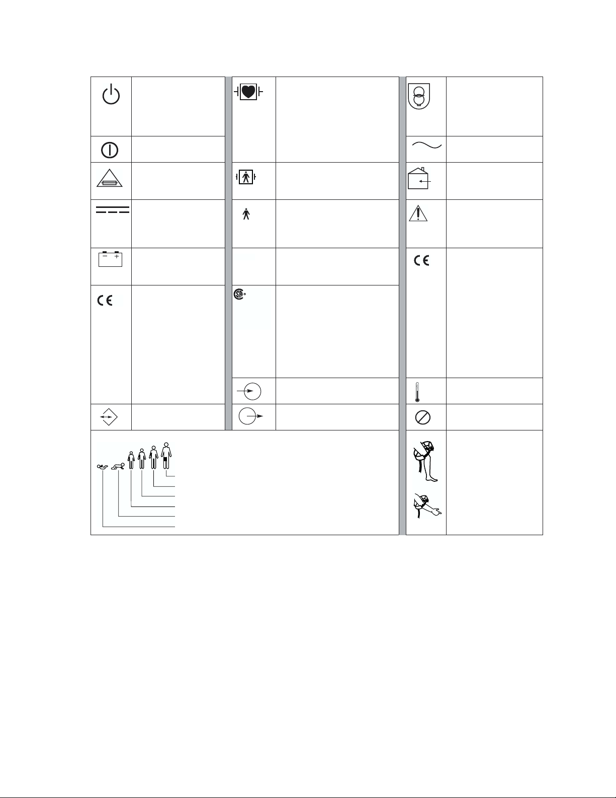
Symbols
The following symbols may appear on the Propaq Encore monitor or accessories or
documentation. These internationally recognized symbols are defined by the International
Electrotechnical Commission, IEC 878 and IEC 417A.
Notes identify useful tips or points about operation.
Caution Caution statements identify conditions or practices that could result
in damage to the equipment or other property.
Warning Warning statements identify conditions or practices that could result
in personal injury.
Propaq Encore Reference Guide 11 Welch Allyn
Page 12
Safety Summary
Off (Standby) Patient connections are Type
CF, isolated for direct cardiac
application, and protected
against defibrillation.
On
Tr ansformer meets
requirements of a
short-circuit-proof
safety-isolating power
transformer.
Alternating current
For continued fire
protection, use only
the specified fuse.
Direct current
Battery charging when
green indicator
illuminated
The CE Mark and
0123
Notified Body
Registration Number
signify the device has
met all essential
requirements of
European Medical
Device Directive
93/42/EEC.
Tw o way
communication port
NIBP cuff sizes:
Thigh
Large adult
Adult
Small adult
Child
Infant
IPX1
NRTL/ C
Evaluated to CSA 601-1
and UL2601-1
Patient connections are Type
BF, and protected against
For indoor use only (on
power adapter only)
defibrillation.
Patient connections are Type
B.
Caution: Refer to
Reference Guide and
accompanying
documentation.
Enclosure Protection Drip
proof: Classification IPX1 per
IEC Publication 529
The Canadian
StandardsAssociation has
evaluated this device
according to CSA 601-1 and
Underwriters Laboratory
Standard UL 2601-1. (This
The CE Mark signifies
the device has met all
essential requirements
of European Medical
Device Directive
93/42/EEC for a Class
1 product. (This symbol
is on the Universal
Power Adapter.)
symbol is on the Universal
Power Adapter.)
Input port Temperature sensor
input
Output port Single-use only (not
2
reusable).
Apply the NIBP cuff as
shown.
Welch Allyn 12 Propaq Encore Reference Guide
Page 13

Propaq Encore Documentation
Propaq Encore Documentation
The Documentation Set
The Propaq Encore documentation set consists of documents for the clinician, the biomedical
technician, and the department head or purchaser of accessories for the Propaq Encore
monitors.
This Propaq Encore Reference Guide contains important safety and operating information for
the clinician.
The Propaq Encore Service Manual (P/N 810-0696-XX) contains information on how to
properly maintain the Propaq Encore through routine calibration, inspection, and
maintenance.
The Welch Allyn Products & Accessories booklet (P/N 810-0409-XX) provides a
comprehensive list of accessories recommended for Propaq Encore monitors and options.
About This Reference Guide
This Reference Guide provides descriptions and operating information for the Propaq Encore
models 202EL, 204EL, and 206EL, including all available options at the time of this manual's
printing.
Statement of Expectations of the Reader
This Reference Guide was written for the clinician. Although this guide may describe some
monitoring techniques, Welch Allyn expects that you are a trained clinician who knows how
to take and interpret a patient’s vital signs. The Propaq Encore has been designed as a quality
monitor; however, inherent limitations require that good clinical judgment always prevails.
Propaq Encore Reference Guide 13 Welch Allyn
Page 14

Propaq Encore Documentation
Welch Allyn 14 Propaq Encore Reference Guide
Page 15

Getting Started
Introducing the Propaq Encore
Intended Use
Before using the
Propaq Encore on a patient, be sure you understand the Safety Summary at
the front of this book. It provides important information about safely using the Propaq
Encore. The Propaq Encore monitor is intended to be used by skilled clinicians for
multiparameter vital signs monitoring of neonatal, pediatric, and adult patients in health
care facility bedside applications; as well as for intra- and interfacility transport.
Propaq Encore Models and Options
Three models of Propaq Encore monitors are available.
Features common
to all models
206EL Tw o Invasive Pressure Channels
204EL One Invasive Pressure Channel
202EL No Invasive Pressure
Options available
for each model
ECG, 3-lead or 5-lead configurations, 0.05-40/0.5-40 Hz
NIBP, with neonatal, pediatric and adult modes
Temperature, 2 channels: YSI™ 400 and 700 series-compatible connectors
Defibrillator Synchronization
Real-time Analog output of ECG
Electrocautery noise suppression on all channels except Impedance
Pneumography
Pulse Oximetry (SpO
Capnography (CO
Mainstream Capnography (MCO
Sidestream Capnography (SCO
Dualstream Capnography (Both MCO
Impedance Pneumography (RESP) (available only with SpO
Printer
HP-compatible side panel
)
2
) (available only with SpO2):
2
)
2
)
2
and SCO2)
2
)
2
Propaq Encore Reference Guide 15 Welch Allyn
Page 16
Introducing the Propaq Encore
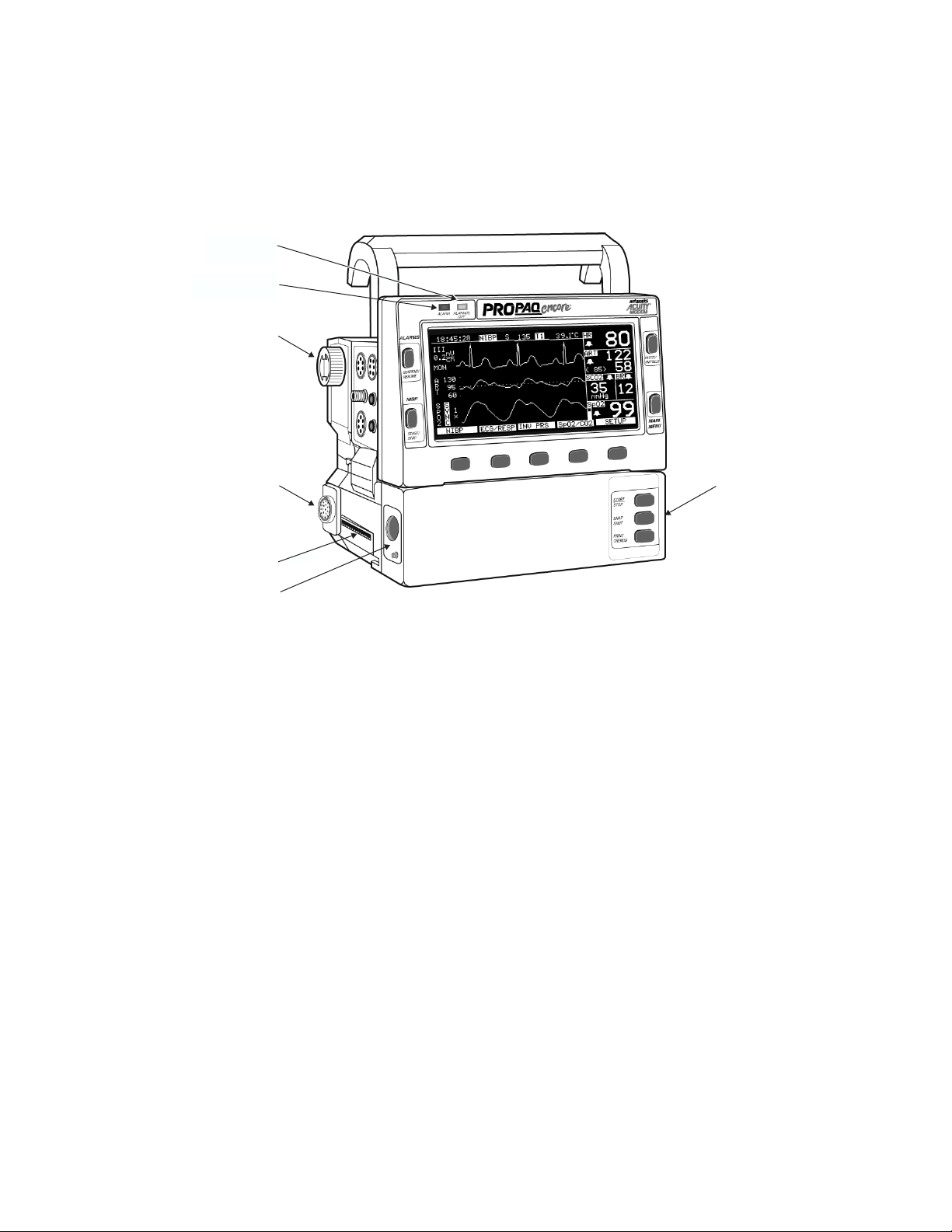
Expansion Module
The Propaq Encore Expansion Module attaches to the monitor and houses additional
capabilities. The Expansion Module can be fitted with the SpO
ALARM(S)
OFF Light
ALARM Light
Option
SpO
2
, CO2, and Printer options.
2
Mainstream
CO
Option
2
Printer Option
Sidestream
CO
Option
2
Expansion
Module
Propaq Encore Pulse Oximetry Option (SpO2)
The Propaq Encore Pulse Oximetry option (SpO2) can be installed in the Expansion Module
or in a smaller unit that attaches to the rear of the monitor:
Masimo
Nellcor
Nellcor
®
Pulse Oximetry option (motion tolerant).
®
Pulse Oximetry option (motion tolerant).
®
Pulse Oximetry option (without motion tolerance).
Capnography (CO2) Options
The Propaq Encore CO
option and Sidestream CO
a ventilator. The Sidestream CO
patients through a cannula. The CO
Dualstream CO
in the Expansion Module. These options require the Pulse Oximetry (SpO2)
2
options allow carbon-dioxide monitoring. The Mainstream CO
2
option allow CO2 monitoring directly in the breathing circuit of
2
option also allows CO2 monitoring of non-intubated
2
options can be installed separately, or together as
2
2
option.
Welch Allyn 16 Propaq Encore Reference Guide
Page 17

Introducing the Propaq Encore
Impedance Pneumography (RESP) Option
The RESP option detects the rate or absence of respiratory effort, and is configured with the
Pulse Oximetry option.
Printer Option
The Expansion Module with Printer (EMP) provides a lightweight 3-channel recorder.
Propaq-to-Acuity Option
This option allows communication between the Propaq Encore and the Acuity Central
Monitoring System by means of an ethernet network system installed in your facility. The
Acuity System operator can view the patient data and control most of the bedside Propaq
functions. The Propaq Encore connects to the Acuity System through an Acuity network
cable that plugs into the Propaq right side panel.
Modem-Propaq Option
This option allows telecommunication between a Propaq Encore and the Acuity System by
means of external modems. This option is configured with the Propaq-to-Acuity option. For
more information refer to the Modem-Propaq Reference Guide.
HP-compatible Side Panel Option
The HP connector-compatible option makes the Propaq Encore compatible with many
Hewlett-Packard sensors and accessories used with the Hewlett Packard Component
Monitoring System. This option replaces the standard Propaq Encore left side panel.
Propaq Encore Reference Guide 17 Welch Allyn
Page 18
Using the Propaq Encore
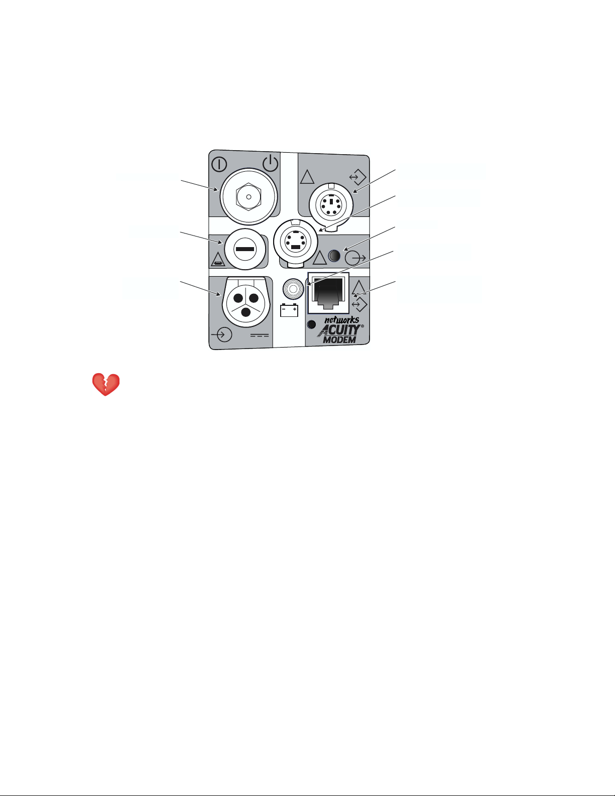
System Controls (Right Side Panel)
Using the Propaq Encore
On/Off Switch
Input Fuse
Power Input
Connector
Warning Safe interconnection between the Propaq Encore and other devices
must comply with applicable medical systems safety standards such as IEC
601-1-1.
On/Off Switch
3A
2AG
12-28V, 3A
DEFIB SYNCHROMONITOR
!
!
EKG x 1000
!
Defib Sync Connector
Real-time ECG
Output Connector
Speaker
Battery Charging
Light
Connector for Acuity
!
or Modem-Propaq
This switch turns the monitor on and off. The switch is recessed to prevent accidentally
turning off the monitor, which would result in losing patient data.
Input Fuse
The input fuse, which protects the Propaq Encore against power surges, is a 3 Ampere fuse,
externally replaceable by qualified service personnel. See page 124 for fuse replacement
instructions.
Power Input Connector
This receptacle accepts the Welch Allyn ac power adapter, which must be used for ac mains
operation and battery charging. The Propaq Encore is also designed to operate with other 1228 volt, dc-only power sources, such as a vehicle battery system.
Welch Allyn 18 Propaq Encore Reference Guide
Page 19

Using the Propaq Encore
Defib Sync Connector
This connector allows connection with a LIFEPAK 5 or LIFEPAK 6s defibrillator for
synchronized cardioversion. See page 131 for more information.
Real-Time ECG Output Connector
This connector provides a real-time analog ECG signal output.
Battery Charging Light
This green light turns on when a power source (ac power adapter or external dc source) is
connected and the battery is charging. Although the monitor may be turned off, battery
charging continues when an external power source is connected.
Connector for Acuity or Modem-Propaq
This connector allows either direct connection to an Acuity System, or connection to an
external modem for telecommunication to an Acuity System. For more information about the
Acuity System, see page 115. For more information about the Modem-Propaq, refer to the
Modem-Propaq Reference Guide.
Alarm Lights
Alarms and limits are described in detail beginning on page 91.
ALARM Light
When an alarm limit is violated, the red ALARM light turns on.
ALARM(S) OFF Light
When any alarm limit is turned off, the yellow ALARM(S) OFF light turns on.
Propaq Encore Reference Guide 19 Welch Allyn
Page 20

Power-up Screen
Using the Propaq Encore
PROTOCOL SYSTEMS INC.
MODEL PROPAQ 204
DIAGNOSTICS IN PROGRESS
BATTERY: 8.3 VOLTS
SOFTWARE VERSION 2.00.00
(c) PROTOCOL SYSTEMS INC. 1988-1998
A few seconds later, the top
two lines of the screen are
replaced with text indicating the
current patient mode (adult,
pediatric, or neonatal).
(c) PROTOCOL SYSTEMS INC. 1988-1998
PEDIATRIC MODE
DIAGNOSTICS IN PROGRESS
SOFTWARE VERSION 2.00.00
When you first turn on the monitor,
the power-up screen displays
information about the Propaq
Encore and the monitor runs
diagnostic tests to ensure proper
functioning.
BATTERY: 8.3 VOLTS
Warning Before you use a Propaq on a new patient, always turn off the
Propaq for a few seconds, then turn it on again. This clears the prior patient’s
trend values, alarm limit settings, and NIBP cuff inflation target.
1. If the Propaq Encore has been used for a previous patient, switch the monitor off,
then on again. The monitor will turn on in the powerup patient mode with the
associated settings.
Verify that the powerup tone is produced. If the monitor has SpO2, verify two
tones are produced to make sure that both speakers are working.
2. Verify the monitor is in the correct patient mode according to the patient’s age. If the
patient mode is not correct, change it (see page 29 to change the patient mode).
Warning Always check the patient mode when monitoring a new patient. The
patient mode determines default alarm limits, maximum cuff inflation pressure,
and internal algorithm settings.
3. Verify the battery voltage is sufficient for monitoring. If it is less than 7.4 V, connect to
a power adapter (see page 119 for information about the power adapter).
Welch Allyn 20 Propaq Encore Reference Guide
Page 21

Using the Propaq Encore
Powerup Equipment Alert: Program Fault, Settings Lost
If a PROGRAM FAULT: SETTINGS LOST, TIME/DAY RESET equipment alert appears when
you turn on the monitor, the monitor cannot recall the programmed custom settings and
current time and date. This can occur if the battery is drained or after new software has been
installed.
If this occurs, the monitor provides a special sequence of display windows to help you regain
use of your monitor as quickly as possible. Do the following:
1. Connect an ac power adapter to recharge the battery (if the battery is drained).
2. Press any button below the equipment alert screen to acknowledge the alert. The
monitor will display the Mode Setup window (shown on page 33).
3. Press these buttons to select one of the Factory patient modes for use:
Factory Adult mode
POWERUP*, YES.
Factory Pediatric mode NEXT, POWERUP*, YES.
Factory Neonatal mode NEXT, NEXT, POWERUP*, YES.
After you press
4. Press
NEXT, UP, and DOWN as needed to set the time and date. Then press ENTER to store
YES, the monitor will display the Time/Day window.
the new time and date.
These display screens are only displayed in this order if the PROGRAM
FAULT equipment alert occurs.
5. Turn off the monitor, then turn it on again so the settings will take effect.
The monitor is ready for use. If you want to store some customized patient mode program
settings, refer to page 33.
If you follow these steps and the equipment alert reappears at powerup, the monitor may
need to be serviced and the battery replaced. Contact a qualified service person.
Propaq Encore Reference Guide 21 Welch Allyn
Page 22
Using the Propaq Encore
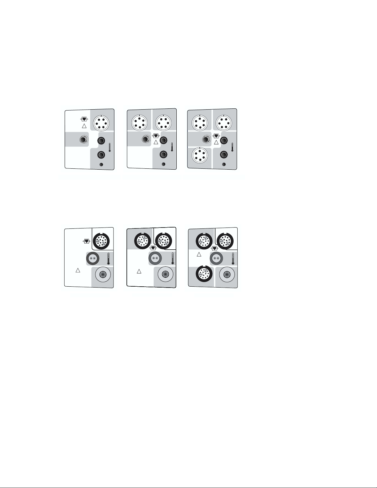
Patient Connections
The left side panels differ depending on the Propaq Encore model. All models have ECG,
NIBP, and two temperature connectors. The Propaq Encore 204 left side panel includes one
invasive-pressure connector, and the Propaq Encore 206 includes two invasive-pressure
connectors.
ECG / EKG RESPINV. BP
NIBP
PSNI
ECG / EKG RESP
!
P1
NIBP
T1
PSNI
!
NIBP
PSNI
T1
ECG / EKG RESPINV. BP
P1
T1
!
!
COMPATIBLE
HP
ECG / EKG RESP
P
S
N
I
202 HP
NIBP
ECG / EKG RESP
P
S
N
I
NIBP
T2
INV. BP
P2
Propaq Encore 206 EL
INV. BP
INV. BP
!
COMPATIBLE
HP
P1
P2
206 HP
T2
Propaq Encore 204 ELPropaq Encore 202 EL
INV. BP
!
COMPATIBLE
HP
P1
204 HP
ECG / EKG RESP
P
S
N
I
NIBP
T2
On Propaqs with the Hewlett-Packard connector option, all models have only one
temperature connector, the YSI 400 connector.
Welch Allyn 22 Propaq Encore Reference Guide
Page 23
Using the Propaq Encore
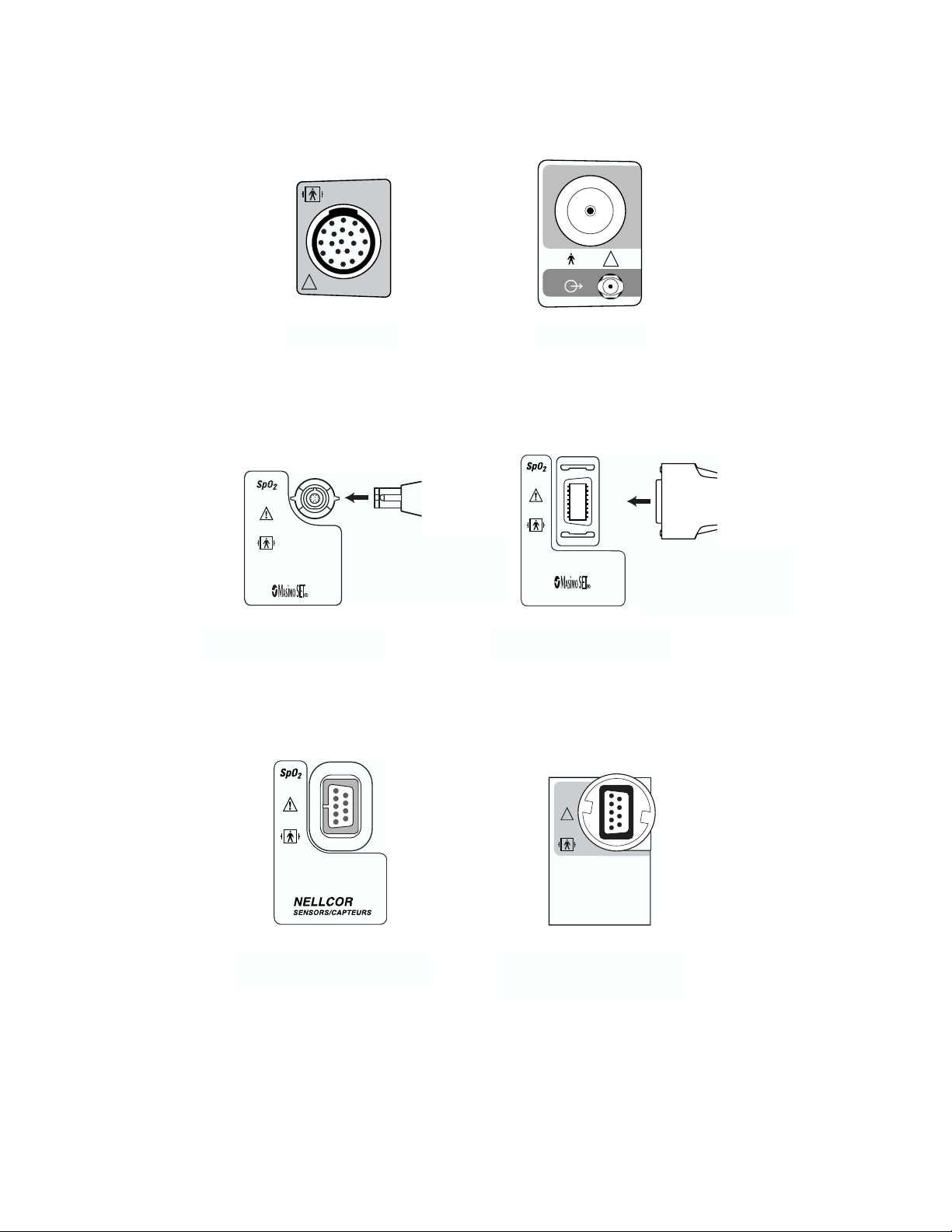
Option Connectors
CO
2
CO
2
!
!
Mainstream CO2
Connector
Masimo SpO2 Connector
(motion tolerant)
Cable: see Welch Allyn
Products and
Accessories Guide
(810-0409-XX)
Sidestream CO2
Connector
Cable: see Welch Allyn
Products and
Accessories Guide
(810-0409-XX)
Masimo SpO2 Connector
(motion tolerant)
SpO
2
!
NELLCOR
SENSORS/ CAPTEURS
Nellcor SpO2 Connector
(newer style, motion tolerant)
Nellcor SpO2 Connector
(older style, without motion
tolerance)
Propaq Encore Reference Guide 23 Welch Allyn
Page 24
Using the Propaq Encore
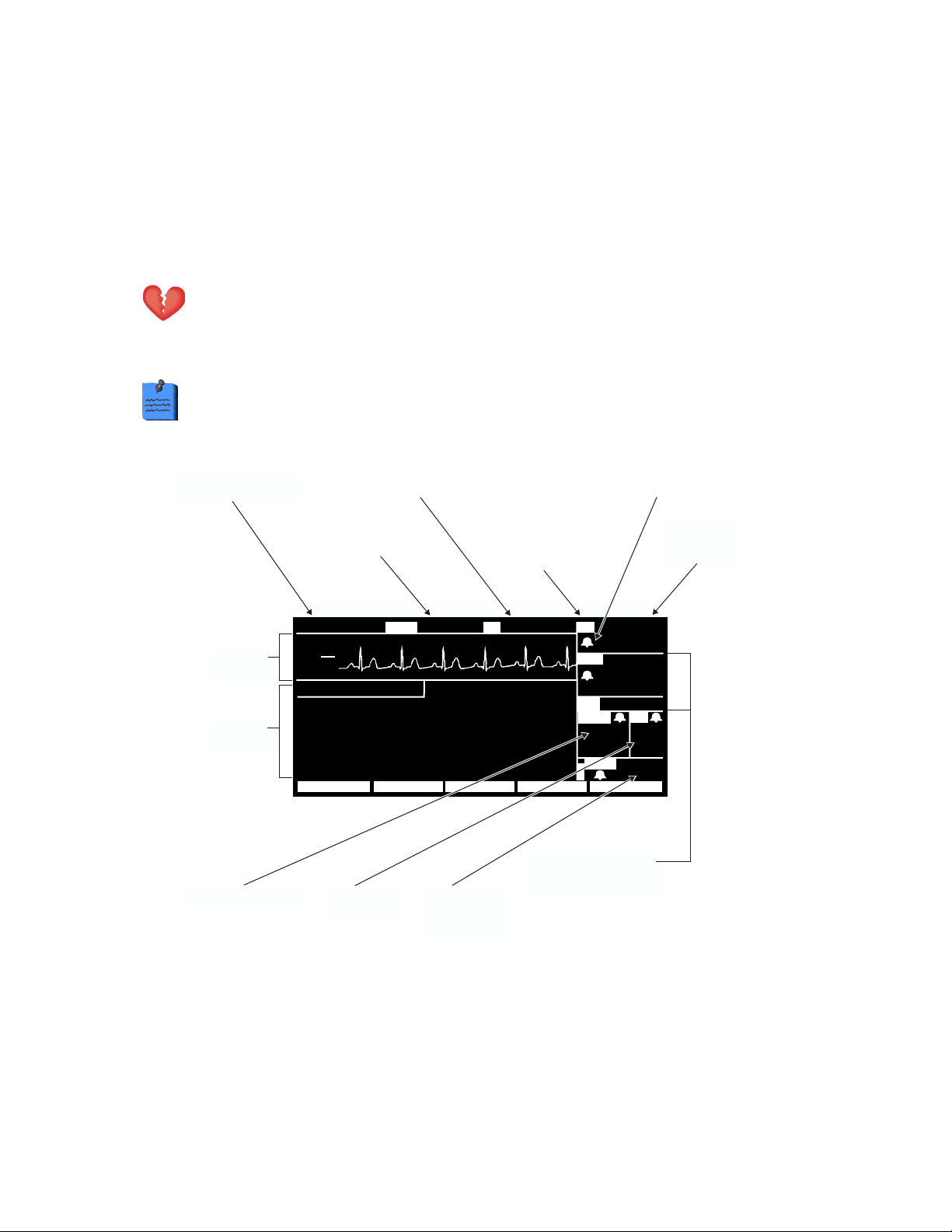
Propaq Encore Display
The display shows waveforms, vital sign numeric values, Propaq Encore status, and alarm
information in different windows. Different vital sign numeric values (such as heart rate and
blood pressures) have upper and lower range limits. If the Propaq Encore detects a vital sign
value outside of the Propaq's measurable range, the monitor displays – – – (below the range)
or + + + (above the range) instead of the vital sign value.
Warning The Propaq Encore will show + + + for HR numerics between 301350 beats per minute. Above 350 beats per minute, it may display incorrectly
low heart rates, due to intermittent picking of R-waves.
Due to differences in software versions and standards required by different
countries, the displays shown in this reference guide may be slightly different
than the display on your Propaq Encore.
Time of day, caution and
status messages.
Noninvasive blood
pressure values can
appear here.
18:45:28
III
Wavefo rm
window
Status
window
ETCO2 concentration Breath Rate
mV
1
cm
MON
CO2
GAS COMPENSATION: OFF
RESPONSE : NORMAL
CO2 SOURCE : MAINSTREAM
SWEEP SPEED : 6.25 mm/s
BAROMETER : 762.2 mmHg
GAS COMP PREV MENUSOURCERESPONSE
from CO
Temperature values are
displayed here.
122
S
Oxygen
saturation is a
2
percentage
value.
Heart Rate Source: HR
indicates ECG;
PR indicates blood
pressure or SpO
102.3
Systolic, diastolic, and (if
pressures are displayed.
.
2
°
F
HRT1NIBP
ART
( 85)
PA
MCO2
35
mmH
SpO
space permits) mean
Bells indicate alarm
limit status
Heart Rate in
60
122
58
35/ 18
BR
12
g
2
92
beats per
minute.
The screenspace is reallocated when vital signs are added or removed. By changing the size
of the numeric windows below the heart rate, the Propaq Encore provides the best possible
view of all numerics for vitals signs being monitored.
Welch Allyn 24 Propaq Encore Reference Guide
Page 25
Using the Propaq Encore
You can select up to three waveforms to be shown on the Propaq. When only one waveform
is selected, a trend window automatically appears below the waveform. While changing
Propaq Encore settings, a status window may appear below the waveform.
12:45:28
III
mV
1
cm
MON
RESP TREND
TIME INCO2ETCO2HR/PR
10:00
9:58
9:56
9:54
BPMHH:MM
101
88
93
91
PRINT OXYCRGNXT TRND
SpO2
%
98
SRCH
OFF
100
122
S
BR
Br/M
11
11
5
10
1NIBP
mmHgmmH
30
31
30
30
102.3
°
3
3
10
2
F
HRT
80
ART
g
( 85)
PA
MCO
2 BR
35
mmH
SpO
122
58
35/ 18
g
2
12
92
Patient waveform and trend
information can be
simultaneously displayed,
while numeric values are
continuously updated.
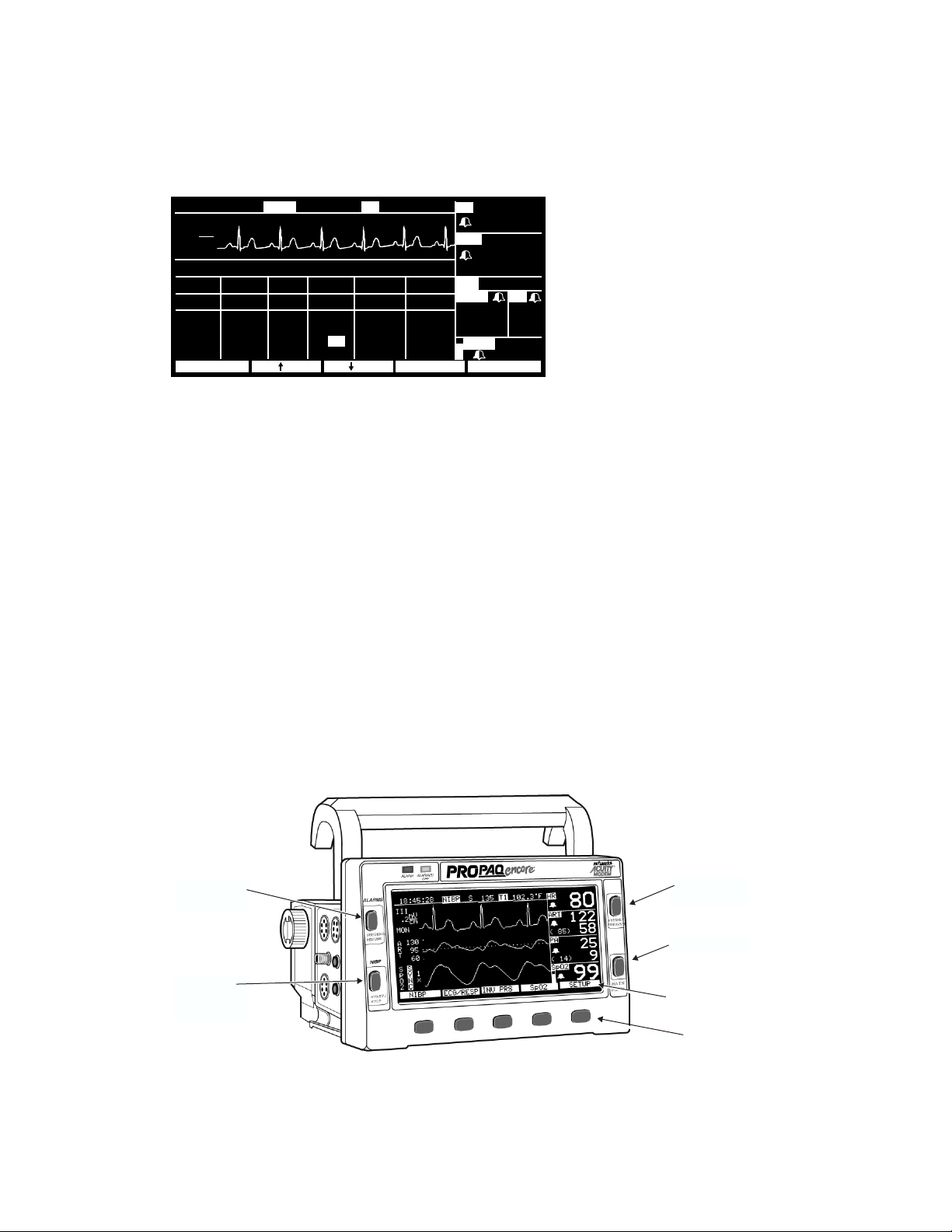
Propaq Encore Buttons
The four buttons at the sides of the screen are reserved for the most commonly used
functions.
SUSPEND/RESUME Suspends or resumes alarm tone.
START/STOP Starts and stops NIBP measurements. The STOP function will
automatically vent the cuff.
FREEZE/UNFREEZE Freezes or “unfreezes” the waveforms. If only one or two waveforms
are displayed and you press FREEZE, the frozen waveform(s) are shown
along with an active waveform so you can continue to monitor the
patient’s condition.
MAIN MENU Pressing MAIN MENU always returns the monitor to the top level menu.
SUSPEND/
RESUME
START/
STOP
(NIBP)
FREEZE/
UNFREEZE
MAIN MENU
The five labels
above the
associated
buttons
Propaq Encore Reference Guide 25 Welch Allyn
Page 26
Using the Propaq Encore
The five buttons below the screen, and their associated labels located on the screen, provide
access to the menus.
Later in this manual, the notation
A , B , C is used as a shorter way to say “Press Button A, then
B, then C.”
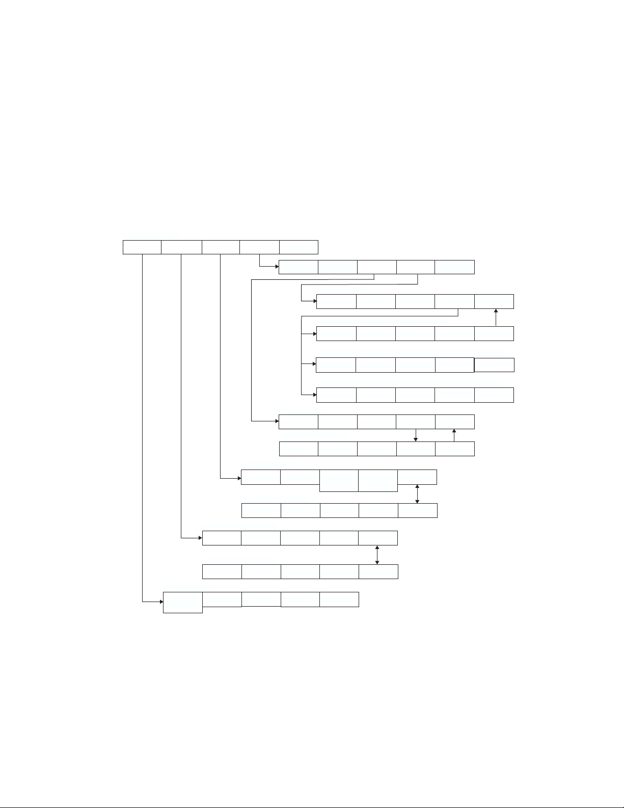
Propaq Encore Menus
Menus for some patient vital signs are displayed only if that option is included in your
Propaq.
MAIN MENU
SETUPNIBP ECG/RESP INV PRS SpO2/CO2
MORE
PREV MENU
FLOWRATE
PREV MENU
PREV MENU
PREV MENURANGE mm/s MORE
PREV MENU
PREV MENU
PREV MENU
INV PRS MENU 1
RANGE
INV PRS MENU 2
LABEL P1 FORMAT 1 LABEL P2 FORMAT 2
ECG/RESP MENU 1
ECG SIZE
SpO2 CO2
CO2 MENU 1
CO2 MENU 2A (NO CO2 SENSORS)
GAS COMP RESPONSE
CO2 MENU 2B (MAINSTREAM CO2 ACTIVE)
GAS COMP RESPONSE SOURCE
CO2 MENU 2C (SIDESTREAM CO2 ACTIVE)
GAS COMP RESPONSE SOURCE
SpO2 MENU 1
SIZE MORE
SpO2 MENU 2
RESPONSE C-LOCK
RESCALE
ECG LEAD RESP SZE
ZERO P1
CANCEL
ZERO P2
CANCEL
MORE
PREV MENU
ECG/RESP MENU 2
NEXT CHANGE
NIBP MENU
START AUTO/MAN TURBOCUF
STOP
INTERVAL
PREV MENU
PREV MENU
Welch Allyn 26 Propaq Encore Reference Guide
Page 27

Using the Propaq Encore
Key-press Route to Setup Menu 1
SETUP MENU 1
STATSCALE
ALARMS
TRENDSWAVE SEL
ALARMS MENU
STAT SET
SUSPEND
RESUME
SETUPNIBP ECG/RESP INV PRS SpO2/CO2
MORE
(MORE button takes you to next Setup Menu)
TRENDS MENU
PRINT NXT TRND
ALL ALRM LIMITS
PREV MENU
ALARM LIMITS MENU*
NEXT
UP DOWN ON/OFF
(*ON/OFF button is not displayed for HR/PR alarm limits if
the HR/PR ALARM LIMITS setting is set to CANNOT
TURN OFF.)
OXYCRG
NEXT PAGE
Propaq Encore Reference Guide 27 Welch Allyn
Page 28
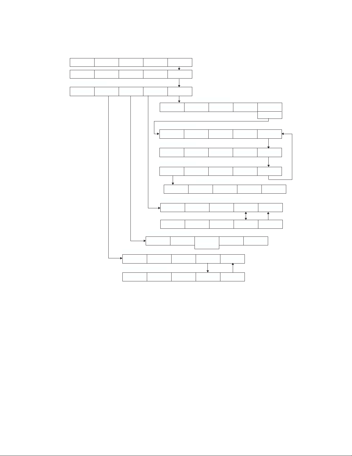
Key-press Route to Setup Menu 2
Using the Propaq Encore
SCATSCALE ALARMS TRENDSWAVE SEL
SETUP MENU 2
NEXT CHANGE WAVE SEL PRINTER
SETUPNIBP ECG/RESP INV PRS SpO2/CO2
MORE
MORE
*(Service menu tests are for use by authorized
service personnel only, and are available only
when in the Adult patient mode.)
TIME/DAY MENU
NEXT UP DOWN ENTER
SERVICE
PREV MENU
SERVICE MENU 1*
MORENIBP TEST IBP TEST SpO2 TST CO2 TEST
SERVICE MENU 2*
TEMP TEST
PIXL TST
NET TEST
MORE
SERVICE MENU 3*
MORESETTINGS KEY TEST SYSTEM
SETTINGS MENU
PREV MENUNEXT CHANGE
PRINTER SETUP MENUS
(Printer Setup status window)
PREV MENUNEXT CHANGE PR TREND MORE
(Printer Trend Select status window)
NEXT CHANGE PR TREND MORE
PREV MENU
WAVE SELECT MENU
ON/OFFNEXT
INSERV
NO INSRV
PREV MENU
PATIENT MODE MENU
PREV MENUNEONATAL PED ADULT SETUP
(Patient Mode menu is
accessed when CHANGE is
pressed for PATIENT
MODE.)
MODE SETUP MENU
PREV MENUNEXT POWERUP* USE NOW SAVE
Welch Allyn 28 Propaq Encore Reference Guide
Page 29
Monitor Setup
Monitor Setup
Setup Menu 1 is accessed by pressing the SETUP button on the Main Menu.
STATSCALE MOREWAVE SEL TRENDSALARMS
STATSCALE
ALARMS Allows access to the Alarms menu.
WAVE SEL Allows you to turn on and off desired waveforms or NIBP
Automatically readjusts all waveform scales.
numerics for display.
TRENDS
MORE
NEXT
CHANGE
PRINTER Allows access to the Printer Menu.
Allows access to the Trend settings and display.
Displays the next setup menu and the following status window:
SETUP HR/PRHR/PR RR/BR
CURRENT SOURCE : ECG MCO2
SELECTED SOURCE : ART --SWEEP (mm/s) : 12.5 3.13
ALARM TONE : HIGH
HR/PR TONE : LOW
PATIENT MODE : ADULT
NEXT MOREWAVE SEL PRINTERCHANGE
( 85)
PA
MCO
2 BR
35
mmH
SpO
35/ 18
g
2
12
92
Selects the next setting in the status window.
Changes the currently selected display setting. (Pressing CHANGE at
PATIENT MODE allows you to choose between Adult, Pediatric, and
Neonatal in a Patient Mode window.)
MORE
CURRENT SOURCE When the selected HR/PR source is no longer available, the current
Allows access to the Time/Day window.
source is the active source with highest priority. The RR/BR source
cannot be manually selected. It will always be CO2 if CO2 is active.
Otherwise, it will be ECG/RESP.
SELECTED SOURCE The user-selected HR/PR source is displayed along with the HR/
PR source currently being used by the monitor.
SWEEP (mm/s) The selectable sweep speeds for HR/PR are 12.5, 25, and 50 mm/
sec. The sweep speeds for RR/BR are 3.13, 6.25, and 12.5 mm/sec.
ALARM TONE Sets the Alarm Tone volume to HIGH, MEDIUM, or LOW.
Propaq Encore Reference Guide 29 Welch Allyn
Page 30

Monitor Setup
HR/PR TONE Sets the Heart Tone volume to HIGH, MEDIUM, LOW, or OFF.
PATIENT MODE Pressing CHANGE in this selection displays the following Patient Mode
window:
PATIENT MODE
SELECT PATIENT MODE BASED ON AGE:
NEO : < 44 WEEKS GEST. AGE
PED : > 44 WEEKS GEST. AGE,
< 9 YEARS
ADULT: > 9 YEARS
NEONATAL PREV MENUADULTPED
BATTERY: 9.2 VOLTS
SETUP
( 85)
PA
35/ 18
MCO2 BR
35
12
g
mmH
SpO
2
92
If you press NEONATAL, PED, or ADULT, a confirmation window
appears, requiring you to confirm your selection:
PATIENT MODE
CHANGING SETTINGS AND MODE
TO:
CUSTOM: ADULT
ADULT ALARM LIMITS WILL BE SET
ARE YOU SURE?
YES NO
( 85)
PA
MCO
2 BR
35
mmH
SpO
35/ 18
g
2
12
92
Whenever you change the patient mode, the alarm limit
settings are automatically changed to the defaults for that
mode. If Custom settings have been set for that mode, the
defaults are the Custom mode settings. If no Custom settings
have been set, the defaults are the Factory Mode settings.
See page 33 for more information about patient modes.
If you change the patient mode, the CO
alarm limits in the
2
new mode might vary slightly from the originally-programmed
CO
limits for the new mode. Check the CO2 alarm limits.
2
If you press
SETUP in the previous Patient Mode window, the
Mode Setup window appears. This allows you to set custom
patient modes and powerup defaults as described on
page 33.
Welch Allyn 30 Propaq Encore Reference Guide
Page 31

Monitor Setup
Selecting Waveforms for Display
To select waveforms for display, press SETUP, WAVE SEL. Use the NEXT and ON/OFF buttons to turn
on the desired waveforms in the wave select window:
SETUP
ECG : ON RESP : OFF
ART : ON SpO2 : ON
PA : OFF NIBP : ON
CO
2 : OFF
NEXT PREV MENUINSERVON/OFF
WAVE SELECT
( 85)
PA
MCO
2 BR
35
mmH
SpO
35/ 18
g
2
12
92
Display Priorities
You can turn on more than three waveforms, but only the first three waveforms listed in the
wave select window that are monitored are displayed. The patient parameters being
monitored are listed in the order they will be displayed if all are turned on.
Because of the critical nature of the ECG waveform, you cannot turn off ECG. However, if
ECG is not monitored, another waveform will occupy its place.
The displayed waveforms are also the ones printed if a printer is attached.
Setting the Time and Date
To set the time and date, from the Main Menu press SETUP, MORE, MORE. The monitor displays
the Time/Day window:
TIME/DAY
TIME DAY
H:MIN:S MO/DA/YR
07:45:32 06/12/97
NEXT PREV MENUDOWN ENTERUP
Press
NEXT, UP, and DOWN as needed to set the time and date. Then press ENTER to store the new
BATTERY: 9.2 VOLTS
( 85)
PA
MCO
2 BR
35
mmH
SpO
35/ 18
g
2
12
92
time and date.
Propaq Encore Reference Guide 31 Welch Allyn
Page 32

Monitor Setup
Time/Day Settings and Trends
Warning Changing the hour/minute/second setting for the monitor in the
Time/Day window can cause the monitor to erase previously stored patient
trend data.
When you change the hour/minute/second setting for the monitor in the Time/Day
window, the monitor deletes any patient trend data that is older than five hours for nonNIBP trends or older than eight hours for NIBP trends according to the new clock setting.
However, if the monitor has not yet stored the full capacity of trends and you change the
hour/minute/second setting to a time that is within the stored trend period, previously
stored trends are not erased.
Changing the day, month, or year setting does not affect the stored patient trends.
Changing the Date Format, Filter, and Units
To change the date format, ECG filter, or some measurement units, first make sure you are in
the Adult patient mode. Then press
Menu)
, MORE, MORE, SETTINGS. The monitor displays the Settings window:
SETUP, MORE, MORE, SERVICE, YES (to access the Service
SETTINGS
DATE : MO/DA/YR
FILTER : 60 Hz
TEMP F/C :
DECIMAL : .
HR/PR ALARM LIMITS: CAN TURN OFF
CO
2 UNITS: mmH
NEXT PREV MENUCHANGE
NEXT
CHANGE
DATE Sets the date format: Month/Day/Year, Day.Month.Year, or Year/
BATTERY: 9.2 VOLTS
°
C
g
( 85)
PA
MCO
35
mmH
SpO
35/ 18
2 BR
12
g
2
92
Selects the next setting in the status window.
Changes the currently selected display setting.
Month/Day.
FILTER Sets the ECG filter frequency. Make sure it is set to your ac mains
frequency.
TEMP F/C Sets the temperature display units: either degrees Fahrenheit or Celsius.
If you change the units, the TEMP trends will not be cleared.
Welch Allyn 32 Propaq Encore Reference Guide
Page 33

Monitor Setup
DECIMAL Sets the decimal character as either a period (.) or a comma (,).
HR/PR ALARM
LIMITS
Allows or prohibits turning off the HR/PR alarm limits. If CANNOT
TURN OFF is selected, the
ON/OFF button is not displayed on the HR/PR
Alarm Limits Menu.
CO2 UNITS Sets the CO2 display units as mmHg, kPa, or percent (%). If you change
the units, the CO2 trends will be cleared and CO2 alarm limit settings
change to the factory default settings for the currently-used patient
mode.
Any time you change the Date, Filter, Temp F/C, Decimal, HR/PR Alarm
Limits (CAN or CANNOT TURN OFF) or
CO
Units setting, the new setting
2
also becomes the powerup default setting.
Setting the Current, Custom, and Powerup Modes
The Propaq Encore has two sets of patient mode settings:
• Factory patient modes. The powerup settings and alarm limits for these patient
modes are preset and cannot be changed. They are listed in Appendix B on page 158.
• Custom patient modes. You can customize the powerup settings and alarm limits for
these patient modes. (See
SAVE on page 34.)
Warning If any alarms are set to OFF and you select
SAVE to store the
settings for that CUSTOM patient mode, those alarms will be OFF whenever
the Propaq powers up in that CUSTOM patient mode or when that CUSTOM
patient mode is selected. Consider carefully before setting CUSTOM patient
mode powerup alarms to OFF.
The alarm for apnea cannot be turned off at any time.
You can program the Propaq Encore to power up in any of the Factory patient modes or the
Custom patient modes. You can also change the current patient mode during operation.
Propaq Encore Reference Guide 33 Welch Allyn
Page 34

Monitor Setup
Whenever you change the patient mode, the alarm limit settings automatically
change to the settings for that mode.
From the Main Menu, press SETUP, MORE, CHANGE, SETUP. The Mode Setup window appears:
MODE SETUP
FACTORY:
CUSTOM
:
* = PATIENT MODE ON POWERUP
NEXT PREV MENU
POWERUP*
BATTERY: 9.3 VOLTS
*ADULT PED
ADULT PED
USE NOW
NEO
NEO
SAVE
P2
MCO
38
mmH
Sp02
ZEROED
NO ZERO
2 BR
12
g
97
The asterisk (*) indicates which patient mode is currently selected for powerup.
NEXT
POWERUP*
Selects the next setting in the status window.
Selects the highlighted patient mode (and its associated settings) as the
powerup mode. The selected powerup mode is marked by an asterisk (*).
(This does not change the current patient mode.)
USE NOW
Selects the highlighted patient mode (and its associated settings) as the
current patient mode. (This does not affect the powerup mode.)
SAVE
Use this button to reprogram the settings of Custom patient mode:
1.
Make sure the patient mode you want to reprogram (ADULT, PED or NEO) is
currently-used (to change patient modes, highlight the desired mode and
press USE NOW, YES).
2. Exit the Mode Setup window, then use other menus and buttons to set the
monitor settings and alarm limits as desired.
3. Re-enter the Mode Setup window, highlight the desired Custom mode, and
press SAVE, YES.
Welch Allyn 34 Propaq Encore Reference Guide
Page 35

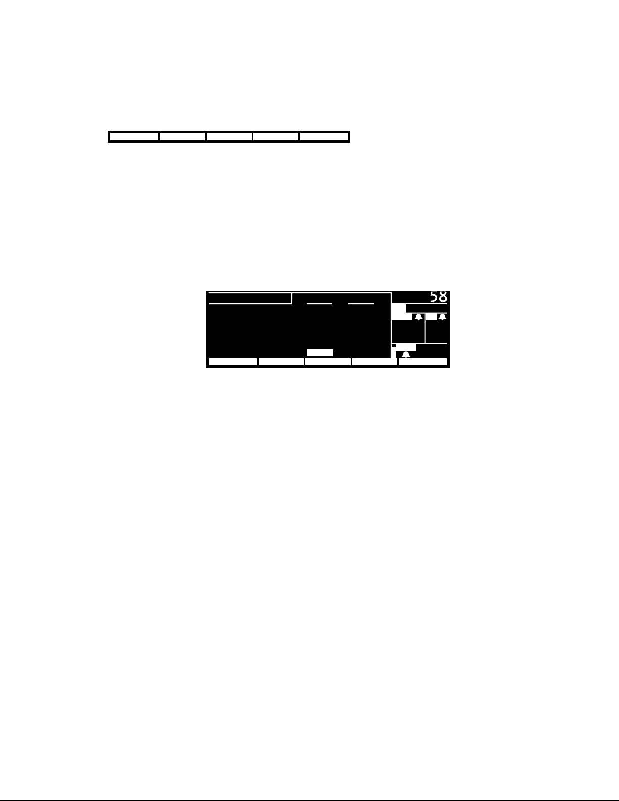
Printer Functions
Printer Functions
Press SETUP, MORE, PRINTER to display the printer menu and setup window.
18:45:28
III
mV
1
cm
MON
PRINTER SETUP PAGE
CONTINUOUS : 25.0 mm/s
AUTO PRINT : 15 minutes
ALARM PRINT : OFF
NIBP TICKET
APNEA TICKET : OFF
OXYCRG ON ALARM: OFF
NEXT MORE PREV MENUPR TRENDCHANGE
NEXT
CHANGE
PR TREND Prints all trends turned on in the Printer Trend Select Window.
MORE
PREV MENU
CONTINUOUS Sets the print speed for real time (continuous) measurements to 6.25, 12.5,
AUTO PRINT Automatically prints 8 seconds of patient information every 15
122
S
: OFF
Selects the next setting in the status window.
Changes the currently selected display setting.
Pressing the MORE button displays another menu and status window.
Returns you to the previous menu.
or 25 mm/sec. This sets the print speed for a printout obtained by
pressing the START/STOP button on the printer.
102.3
°
F
HRT1NIBP
80
ART
122
58
( 85)
PA
35/ 18
MCO
2 BR
35
mmH
SpO
12
g
2
92
minutes, 30 minutes, 1 hour, 2 hours, or 4 hours. This is the latest
patient information (real time). The print speed is automatically set
to 25 mm/sec.
ALARM PRINT Automatically prints upon an alarm. The Propaq Encore prints 20
seconds of patient information. The first 12 seconds contain
information prior to the alarm. The print speed is automatically set
to 25 mm/sec.
NIBP TICKET Automatically prints an NIBP Ticket when the measurement is
taken.
APNEA TICKET When turned on, an Apnea Ticket is printed at the conclusion of an
apnea alarm and at the one-minute clock interval if the apnea alarm
does not cease.
OXYCRG ON ALARM When turned on, an oxycardiorespirogram will print if an HR/PR,
SpO
, or RR/BR alarm occurs. For more information on OxyCRG,
2
see page 112.
Propaq Encore Reference Guide 35 Welch Allyn
Page 36

PRINTER FAULT Messages
These PRINTER FAULT messages can appear in an equipment alert window.
Printer Functions
LOW BATTERY,
PRINTER DISABLED
This message appears when the Propaq’s battery voltage is
less than 7.6 volts. To continue operation, plug the ac power
adapter into the Propaq.
CHECK DOOR The door on the bottom of the printer is open. Close door to
remove this message.
PAPER OUT T
o add printer paper, see page 128.
OVERHEATING The printer is overheating. Service may be required.
The front panel of the printer lets you control the basic printer functions.
Manually starts and stops a printout of
patient information as it is monitored
(continuous or real time).
START
Hold down top
and bottom keys
simultaneously to
generate a
test strip.
STOP
SNAP
SHOT
PRINT
TRENDS
Hold down top two keys simultaneously to
generate a paper feed.
Prints the last 8 seconds of data for
nonrespiration waveforms and 32
seconds of compressed waveform history
for respiration waveforms.
Prints all trends that are enabled in the
Printer Trend Select Window.
If you press
information obtained prior to when you pressed
FREEZE prior to pressing SNAPSHOT, the printer prints the 8 seconds of patient
FREEZE.
Welch Allyn 36 Propaq Encore Reference Guide
Page 37

Learning the Propaq Encore
Learning the Propaq Encore
Using In-Service Mode
You can practice using the Propaq Encore without a patient simulator by using the Propaq's
in-service mode of operation. The in-service mode cannot be activated while you are
monitoring a patient. The message “SIMULATING” alternates with the time of day and
patient mode on the display.
To begin practicing with your Propaq, disconnect all patient cables connected to the monitor.
Leave the cuff connected so you can take NIBP measurements. If you have been monitoring a
patient, turn off the Propaq Encore and turn it back on. From the Main Menu, press
WAVE SEL, INSERV.
The Propaq Encore has two sets of simulated patient information—an initial set and an
alternate set. To change between them, press the
If you connect a patient cable or set the NIBP channel to automatically take pressure
measurements, the Propaq Encore stops simulating, goes through its powerup tests, and
erases any simulated trend data it might have stored.
INSERV button again.
SETUP,
What You Can Do With In-Service Mode
While using the in-service mode, you can press any of the Propaq Encore buttons, except for
the
AUTO/MAN button in the NIBP Menu, to change a function setting. You can also:
• change the ECG and RESP waveform sizes
• set alarm limits and cancel alarms
•STAT SET alarms
• customize the Propaq Encore settings
• change from
• simulate invasive-pressure zeroing
°F to °C
Propaq Encore Reference Guide 37 Welch Allyn
Page 38

Learning the Propaq Encore
NIBP
For noninvasive pressure measurements, keep the Propaq Encore in manual NIBP operating
mode and take pressure measurements by pressing the
NIBP Menu's
TURBOCUF button to consecutively take pressure measurements for five minutes.
START button. You can also press the
Printer Message
Simulated data can be printed on the Propaq Encore Printer. All printouts include the
message “SIMULATED DATA” every four inches to prevent simulated data from being
mistaken for actual patient data.
What You Cannot Do With In-Service Mode
•You cannot use in-service mode to calibrate the monitor.
•You cannot set the Propaq Encore to take automatic noninvasive pressure measurements
(except Turbocuf) while using in-service mode.
•You cannot use Defib Sync or Real-time ECG output while using in-service mode.
•You cannot activate in-service mode if you have been monitoring a patient.
Welch Allyn 38 Propaq Encore Reference Guide
Page 39

Patient Monitoring
ECG/RESP
Intended Use–Impedance Pneumography (RESP)
The Respiration channel is intended to detect the rate or absence of respiratory effort,
deriving the signal by measuring the AC impedance between the selected terminals of the
ECG electrodes. RESP displays a respiration rate and waveforms. Two respiration lead
selections are available, Lead 1 (RA-LA) and Lead 2 (RA-LL).
Warning Impedance pneumography detects respiratory effort via changes in
chest volume; therefore, impedance pneumography can be used to detect
central apnea. However, apnea episodes with continued respiratory effort,
such as obstructive apnea and mixed apnea, may go undetected. Always
monitor and set alarms for SpO
monitor respiratory function.
With any monitor that detects respiratory effort via impedance pneumography,
artifact due to patient motion, apnea mattress shaking, or electrocautery use
may cause apnea episodes to go undetected. Always monitor and set alarms
for SpO
function.
when using impedance pneumography to monitor respiratory
2
when using impedance pneumography to
2
The Propaq Encore automatically rejects cardiovascular artifact (CVA). This
function is dependent upon accurate ECG R-wave detection. Therefore,
always select the ECG lead with the most prominent QRS complex when
monitoring respiration via impedance pneumography.
Don’t place the Propaq Encore monitor with RESP in close proximity with
another respiration monitor because the RESP measurement frequencies
may interfere with one another.
Because pacemaker pulses in some instances may be falsely counted as
breaths, impedance pneumography is not recommended for use on paced
patients.
Propaq Encore Reference Guide 39 Welch Allyn
Page 40

ECG/RESP
Impedance pneumography is not recommended for use with high frequency
ventilation.
Since RESP is derived from the same leads as the ECG channel, the Propaq
Encore determines which signals are cardiovascular artifact and which signals
are a result of respiratory effort. If the breath rate is within five percent of the
heart rate or a multiple or sub-multiple of the heart rate, the monitor may
ignore breaths and trigger an apnea alarm.
Intended Use–ECG
The Propaq Encore is intended for ECG monitoring of either a five-lead or three-lead
configuration, including the Marriott configuration 1 (MCL1 requires all three electrodes).
The five lead configuration can derive one of seven user-selected signals, Lead I, II, III, aVR,
aVL, aVF, or V.
The monitor will automatically determine if only three lead wires are connected, and will
automatically reduce the number of selectable leads to three (I, II, III). If four-wire ECG
cables are used, they will be handled as if they were three-wire cables.
Warning The Propaq Encore monitor does not have automated arrhythmia
analysis, therefore, some ventricular tachycardias and ventricular fibrillation
may not be interpreted correctly and may display an inaccurate heart rate.
The Propaq Encore 200 series does not have automated ST segment monitoring, although
with ECG set for extended bandwidth, ST segments may be accurately displayed and
printed.
The Propaq Encore ECG’s bandwidth is 0.5-40 Hz in Monitor Mode and 0.05-40 Hz in
Extended Mode. Monitor Mode is useful to minimize baseline wander due to respiration or
other artifact. However, in Monitor Mode, ST segments can be distorted, potentially causing
underestimation of ST elevation and overestimation of ST depression. Always use Extended
Mode when observing ST segment morphology on the display or printer.
The Propaq Encore can be used during procedures using electrosurgical machines and
defibrillators. However, even though the ECG channel contains electrosurgical interference
suppression (ESIS) circuitry, noise artifact may be displayed on the ECG trace while an
electrosurgical device is in use. This will vary depending on ECG electrode placement and
the operative site.
Welch Allyn 40 Propaq Encore Reference Guide
Page 41

ECG/RESP
Warning High-intensity radio frequency (RF) energy from external sources,
such as an improperly connected electrosurgical unit, can induce heat into
electrodes and cables which can cause burns on the patient. Reading errors
and damage to equipment may also result. This hazard can be reduced by (1)
avoiding the use of small ECG electrodes, (2) selecting ECG electrode
attachment points remote from the surgical site and from the electrosurgical
return electrode, (3) using electrosurgical return electrodes with the largest
practical contact area, and (4) assuring proper application of the
electrosurgical return electrode to the patient.
Verify patient mode. Incorrect patient mode may result in inaccurate heart
rates and inappropriate alarm settings.
Even though the Propaq Encore contains fully isolated patient-connected circuitry, it has not
been specially designed for direct cardiac application.
The Propaq Encore can be used on patients with pacemakers. See page 47.
ECG Connector and Applicable Accessories
Use only with accessories provided or recommended by Welch Allyn. Refer to the Welch
Allyn Products and Accessories booklet.
To prevent injury, use the provided garment clips to route the ECG cables away from the
patient’s head.
Warning Use of ECG cables with loose or faulty detachable lead wires may
cause erratic behavior of the ECG waveform, SpO
intermittent ECG lead wire connections.
Caution To protect the Propaq Encore from damage during defibrillation, for
accurate ECG information, and for protection against noise and other
interference, use only ECG electrodes and cables (namely, ones with internal
current-limiting resistors) specified or supplied by Welch Allyn, and follow
recommended application procedures.
, C-Lock, and NIBP due to
2
Propaq Encore Reference Guide 41 Welch Allyn
Page 42

ECG/RESP
Preparation
Warning Use only ECG safety cables that are designed so that they cannot
accidently be plugged into an AC mains outlet or make contact with other
hazardous electrical potentials including earth ground. To prevent damage
during defibrillation, don’t use ECG cables without 1K series resistors.
Preparing for ECG monitoring with the Propaq Encore requires you to prepare the monitor,
prepare the patient, set up the ECG channel, and then set the ECG alarms.
Preparing the Monitor
1. Inspect the ECG cable for wear, breakage, or fraying. Replace the cable if it shows
signs of any of these. Plug the ECG cable into the ECG connector on the Propaq's left
side panel.
Warning Before you use a Propaq on a new patient, always turn it off for a
few seconds, then turn it on again. This clears the prior patient’s trend values,
alarm limit settings, and NIBP cuff inflation target.
2. If the monitor is off, press the OFF/ON switch to turn it on.
3. Select the patient mode appropriate for the patient (Neonatal, Pediatric, Adult). To
change patient modes, see page 29.
Preparing the Patient
1. Thoroughly clean the skin areas where the electrodes will be attached. Attach lead
wires to the electrodes before applying them to the patient.
2. If you are using pre-gelled electrodes, use only electrodes that have not expired.
Make sure there is a generous amount of gel in the electrode and that it has not dried.
For best results, use silver/silver chloride electrodes.
3. If you are using non-gelled electrodes, apply a
electrode contact area.
1
1
/
to
/
4
inch mound of gel over the
2
Welch Allyn 42 Propaq Encore Reference Guide
Page 43

ECG/RESP
Some electrodes may be subject to large offset potentials due to polarization.
This effect is most likely when dissimilar metals are used for different
electrodes, and may be severe enough to prevent obtaining an ECG trace.
Furthermore, recovery time after application of defibrillator pulses may be
compromised when using electrodes of dissimilar metals. Squeeze bulb
electrodes, even if all of the same metal, are particularly vulnerable to this
effect. Stainless steel needle electrodes are prone to having large erratic offset
drifts, and are not recommended.
4. Apply the electrodes to the patient.
RA
Standard 3-lead
Configuration
V1
5-lead Configuration
RA
RL
LL
LL
LA
LA
V6
One of six “v lead”
electrode placement
sites for the fifth (c) lead.
G
+
Marriott
Configuration
MCL 1
If using MCL1, select LEAD II on the Propaq,
and use all three electrodes.
(G)=LA (-)=RA (+)=LL
Neonate 3-lead Configuration
5. Support the ECG cable so it does not stress the electrode wires, ECG cable connectors,
or electrodes.
Propaq Encore Reference Guide 43 Welch Allyn
Page 44

ECG/RESP
Two RESP leads are available. Choose the one that gives you the best signal.
If neither signal is adequate, it may be necessary to experiment with
nonstandard electrode placement such as placing the RA and LA electrodes
on the respective mid-axillary lines just above the level of the nipples.
6. If an electrosurgical unit is going to be used, place the ECG cable and electrode wires
as far as possible from the surgical site and from the electrosurgical return electrode
and its cables. This will minimize interference.
By now there should be some kind of ECG waveform displayed on the monitor. A
heart rate should be displayed to the right of the waveform. Depending on how the
Propaq Encore is programmed, a beep tone may occur with each detected QRS event.
7. If there is no waveform, check the electrodes, wires, cable, and the monitor for a
possible lead fault.
If an ECG electrode becomes disconnected or disrupted so that the Propaq Encore
cannot receive the ECG signal, a message and tone are conveyed with an equipment
alert.
Setting Up the ECG/RESP Channel
Press ECG or ECG/RESP (available with the Impedance Pneumography Option) to set the
selections:
button displays the second ECG/RESP menu and a status window with selections for HR/
PR TONE, PACER DISPLAY, ECG BANDWIDTH, and RESP LEAD (available with
Impedance Pneumography). If the patient being monitored has a pacemaker, you may want
to turn on the Pacer indicator function.
ECG SIZE, ECG LEAD, RESP SZE (available with Impedance Pneumography). The MORE
Setting ECG/RESP Alarms
Set the alarm limits according to your hospital's standards.
Motion artifact or other factors can cause false HR/PR alarms. To help minimize false alarms,
the Propaq delays or “holds off” triggering an HR/PR alarm for 3 seconds. During this
holdoff period, if the Propaq detects that the patient’s HR/PR vital sign has returned to
acceptable limits, the Propaq cancels the alarm holdoff. The next time an HR/PR limit is
violated, the Propaq starts a new 3-second HR/PR alarm holdoff period.
Welch Allyn 44 Propaq Encore Reference Guide
Page 45

ECG/RESP
How ECG/RESP is Displayed
Because of the critical nature of monitoring ECG, it is always displayed in the top part of the
waveform display area. The ECG waveform is the only waveform that cannot be turned off
using the Setup Wave Select Menu.
Respiration rate numerics are sourced from the CO
channel and displayed as BR when CO2
2
is active. Otherwise, respiration rate numerics are sourced from the ECG/RESP channel and
displayed as RR.
Patient Artifact
Patient movement and other artifact might cause the waveform to move on the display. Most
artifact such as this is automatically detected, and the waveform is adjusted so that it always
remains centered in the waveform window.
Severe artifact and interference (such as interference from defibrillation) may cause the
waveform to move off the display. The Propaq Encore will always automatically reposition
the waveform in just a few seconds so you can see it again.
ECG/RESP Menus and Status Window
ECG LEAD RESP SZE MOREECG SIZE
ECG SIZE Selects the ECG waveform size; sizes are shown in millivolts per
centimeter (.2, .5, 1, 2, or 4 mV/cm) to the left of the waveform.
ECG LEAD Selects the ECG lead. The available leads are lead I, II, III, aVR, aVL,
aVF, or V. The Propaq's factory default lead setting is Lead II.
Impedance Pneumography Selections
If your Propaq Encore includes the Impedance Pneumography Option, the following
selection is also available:
RESP SZE Selects the RESP waveform size.
The Size function “increases” and “decreases” the ECG or RESP waveform size. Each time
you press a SIZE button, the waveform approximately doubles in height. When you reach the
largest waveform size, the next press displays the smallest size.
Propaq Encore Reference Guide 45 Welch Allyn
Page 46

ECG/RESP
When you press MORE in the first ECG/RESP Menu, a status window appears showing you
the current ECG/RESP settings and additional selections.
Selected ECG
lead
Sensitivity
factor
Bandwidth
Selection
Available with the
Impedance
Pneumography
Option
HR/PR TONE Sets the heart tone loudness to LOW, MEDIUM, HIGH, or OFF.
18:45:28
III
mV
1
cm
MON
ECG/RESP
HR/PR TONE : LOW
PACER DISPLAY: ON
ECG BANDWIDTH: MONITOR (0.5-40Hz)
RESP LEAD : Ld1 (RA-LA)
RESP : ON
NEXT PREV MENUCHANGE
1NIBP
102.3
°
F
HRT
80
NIBP
122
( 85)
58
PA
35/ 18
2 BR
MCO
35
12
g
mmH
SpO
2
92
If SpO2 is monitored, the pitch of the tone varies with the SpO2 value.
PA CER DISPLAY Turns on and off the pacer indicator in the ECG waveform.
ECG
BANDWIDTH
This selection allows you to determine the bandwidth for the data sent
to the display and the printer. If the selection is Extended, the
bandwidth is 0.05-40 Hz. If the selection is Monitor, the bandwidth is
0.5-40 Hz.
The Size function “increases” or “decreases” the ECG or RESP waveform size. Each time you
press a
SIZE button, the waveform approximately doubles in height. When you reach the
largest waveform size, the next press displays the smallest size.
The QRS detector sensitivity threshold is not affected by changing the ECG
display size. Likewise, the RESP breath detector threshold is not affected by
changing the RESP display size.
Impedance Pneumography Selections
If your Propaq Encore includes the Impedance Pneumography Option, the following
selections are also available.
RESP LEAD
Selects the RESP lead. Choices are RA-LA and RA-LL, and choice is
independent of ECG lead selection. Experiment with placement for best
signals.
RESP
Turns impedance pneumography (RESP channel) on or off.
Welch Allyn 46 Propaq Encore Reference Guide
Page 47

ECG/RESP
The Propaq Encore counts as “breaths” respiratory efforts that are larger than
two times background Cardiovascular Artifact (CVA).
Since RESP is derived from the same leads as the ECG channel, the Propaq
Encore determines which signals are cardiovascular artifact and which signals
are a result of respiratory effort. If the breath rate is within five percent of the
heart rate or a multiple or sub-multiple of the heart rate, the monitor may
ignore breaths and trigger an apnea alarm.
Using the Propaq Encore With Pacemaker Patients
Warning Pacemaker signals can differ from one pacemaker to the next. The
Association for Advancement of Medical Instrumentation (AAMI) cautions that
“in some devices, rate meters may continue to count the pacemaker rate
during occurrences of cardiac arrest or some arrhythmias. Do not rely entirely
upon rate meter alarms. All pacemaker patients should be kept under close or
constant observation.”
Pacemaker Signals
If the patient being monitored has a pacemaker, the Propaq Encore detects and can indicate
the occurrence of pacemaker signals. With the Propaq, pacemaker signals are not counted as
heart beats as long as the pacemaker signal meets the pulse amplitude, pulse width, and
overshoot/undershoot specifications listed in Appendix B.
Pacer Display
On the Propaq Encore display, vertical dashed lines indicate each time a pacemaker signal is
detected when the Propaq Encore PACER function is turned on. The waveform “spike”
produced by the pacemaker will also be displayed if it contains sufficient energy. Whether
the pacer is atrial, ventricular, or both, the indicator and the spike appear. If the PACER
function is turned off, only the pacemaker spike is displayed:
18:45:28
III
mV
1
cm
MON
HR
80
Turn On and Off the Pacemaker Indicator
The status of the pacer display is shown in the ECG status window. Turn PACER DISPLAY
on or off using the
Propaq Encore Reference Guide 47 Welch Allyn
NEXT and CHANGE buttons.
Page 48

ECG/RESP
Noise on the signal
Noise on the ECG signal may be detected as pacer signals, causing the pacer indicator to
appear on the display. If you don't need to indicate pacemaker signals, you may want to turn
off the pacemaker indicator for a better display of the ECG waveform.
Warning The presence of much pacer-like noise can cause the displayed
heart rate to be erratic even though the ECG trace may look clean with the
pacer indicator off. Fix the noise problem by using fresh ECG electrodes and
an ECG cable whose lead wires make good connections.
Using the Filter to Better Display a Waveform
The Propaq Encore includes a filter that reduces noise from the ac power signal and produces
a much clearer ECG waveform. To set the filter, press
the Service Menu),
function with the
Set the filter to the ac mains frequency of your hospital (either 60 or 50 Hz).
MORE, MORE, SETTINGS to display the Settings Menu. Select the FILTER
NEXT button and press the CHANGE button to change settings.
SETUP, MORE, MORE, SERVICE, YES (to access
ECG Messages
If a lead fault occurs, an ECG equipment alert typically shows which lead failed. Otherwise,
the Propaq Encore displays MULTIPLE in place of the failed leads.
ECG LEAD CHANGED. The Propaq Encore has automatically changed an ECG lead
due to a lead wire or electrode problem.
LEAD FAIL: REPLACE ELECTRODES. There is excessive offset on the ECG channel.
Welch Allyn 48 Propaq Encore Reference Guide
Page 49

ECG/RESP
RESP Messages
LEAD FAIL. One or more electrodes are making very poor or no contact. Check for
proper connection; replace electrodes if needed.
INAPPROPRIATE ECG CABLE. ECG cable appears not to contain 1K current limiting
resistors. These resistors are required for RESP operation and to protect the Propaq
Encore from damage during defibrillation. Replace cable with proper type.
NOISY SIGNAL, CHECK ELECTRODES. Electrodes are making poor contact and may
be dried out. Replace electrodes.
Warning If a disconnected lead is in too close proximity to other electrical
devices, it may cause false heart rate, a failure to detect apnea, or a failure to
display a Lead Fail message.
Propaq Encore Reference Guide 49 Welch Allyn
Page 50

Invasive Pressure
Invasive Pressure
This section applies only to Propaq Encore Models 204EL and 206EL. If you don't have one of these
models, you can skip this section.
Intended Use
The Propaq Encore invasive pressure channel is intended for measuring arterial, venous, and
intracranial pressures using invasive transducers with 5 µV/V/mmHg sensitivity. The
Propaq Encore can be used with many types of transducers, including nondisposable,
disposable dome, and fully disposable.
Invasive Pressure Connectors and Transducers
Recommended transducers for use with the Propaq Encore are listed in the Welch Allyn
Products and Accessories booklet. Do not use light-sensitive disposable transducers.
Transducers must be used according to your hospital's standards and the manufacturer's
recommendations. Always refer to the manufacturer's Directions for Use before using the
transducer.
Warning If electrocautery is used, always avoid using any transducer with a
conductive (metal) case that is electrically connected to its cable shield. Using
a conductive transducer case with such a shield connection risks highfrequency burns at the ECG electrodes if the transducer case becomes earth
grounded.
Although complete disconnections of invasive pressure transducers will be
detected by the normal alarm functions, partial disconnection will not be
detected, nor will the use of some incompatible transducers. The user must
exercise reasonable measures to ensure that approved transducers are used
and that pressure transducers are connected properly.
Before you use a Propaq on a new patient, always turn it off for a few seconds,
then turn it on again. This clears the prior patient’s trend values, alarm limit
settings, and NIBP cuff inflation target.
Welch Allyn 50 Propaq Encore Reference Guide
Page 51

Invasive Pressure
Preparation
Preparing for invasive pressure monitoring with the Propaq Encore requires you to prepare
the transducer, zero the transducer, set up the pressure channel, and set the invasive pressure
alarm limits.
Preparing the Transducer
1. Inspect the transducer cable for wear, breakage, or fraying. Replace it if the cable
shows signs of any of these. Replace the transducer dome if necessary.
2. Apply the transducer according to your hospital's procedures. Always refer to the
transducer manufacturer’s Directions for Use.
3. If the transducer is a disposable unit with separate cable, connect the transducer to
the transducer cable. Plug the transducer cable into an invasive pressure connector on
the left side panel.
The message NOT ZEROED (or NO ZERO, depending on the zone) immediately
appears in the blood pressure numerics window for the invasive pressure channel
being used.
18:45:28
III
mV
1
cm
MON
P
1
NIBP
102.3
°
F
HRT1
NIBP
P1
RR
SpO
80
NOT
ZEROED
2
Tr ansducer
message
99
RANGE RESCALE ZERO P1 MOREZERO P2
Zeroing the Transducer
1. To zero the transducer, open the transducer's stopcock to atmospheric air. Allow a
few seconds for the transducer to settle.
2. If the ZERO menu is not displayed, press the following Propaq Encore buttons:
PRS, then ZERO P1 (or ZERO P2). The word ZEROING appears in the numerics window
during zeroing. The button label changes to
process if necessary
CANCEL to allow you to cancel the zeroing
INV
Propaq Encore Reference Guide 51 Welch Allyn
Page 52

Invasive Pressure
3. Wait for a tone to briefly sound and the word ZEROED to appear in the blood
pressure numerics window. You will then see the pressure scale to the left of the
waveform, and the pressure numerics appear.
4. Close the transducer's stopcock.
5. If the transducer will not zero, the words ZERO REJECTED (or NO ZERO, depending
on zone) will appear in the numerics window. Press
You won’t see the pressure values and the scales until an acceptable zero reference is
established.
6. Check that the transducer is open to atmospheric air and that it is properly connected
to the Propaq Encore, then try zeroing again. The Propaq Encore will not allow
zeroing to occur if the pressure waveform is pulsatile, if there is too much noise in the
signal or if the transducer’s offset is too great. Once the channel is zeroed, the
pressure scale appears next to the waveform.
If the transducer still does not zero, try another transducer or another cable.
CANCEL and try zeroing again.
Setting up the Pressure Channel
Press INV PRS to set the invasive pressure channel selections: RANGE, RESCALE, and ZERO P1/
ZERO P2. Press MORE to set LABEL P1/LABEL P2 and FORMAT 1/FORMAT 2.
Setting the Invasive Pressure Alarms
Set the alarm limits according to your hospital's standards.
Rezeroing a Transducer
You can rezero a transducer at any time, after again opening the transducer stopcock to
atmospheric air. If the transducer has already produced pressure readings, rezeroing
provides a new zero reference for the Propaq.
If the zero value is not accepted, the Propaq Encore continues to use the previous zero
reference and displays the pressure values and waveforms based on that value. If the new
zero value is accepted, the new pressure values based on the new zero value are displayed,
and the waveform is adjusted according to the new scale.
Welch Allyn 52 Propaq Encore Reference Guide
Page 53

Invasive Pressure
Warning If a
ZERO button is pressed after an invasive pressure channel has
been successfully zeroed and is currently monitoring a pressure waveform, the
message ZERO REJECTED will display in the invasive pressure numerics
window. This message will preempt the valid invasive pressure numerics until
the
CANCEL button in the Invasive Pressure Menu is pressed.
If the invasive pressure channel enters an alarm condition while the ZERO
REJECTED message is overriding the invasive pressure numerics, no
invasive pressure numerics will flash to indicate invasive pressure is in alarm.
To remove the ZERO REJECTED message and to restore the invasive pressure numerics
during an invasive pressure alarm, you must return to the invasive pressure menu and press
CANCEL. This will restore the invasive pressure numerics.
How Invasive Pressure is Displayed
From the invasive pressure signal, the Propaq Encore displays both a pressure waveform and
pressure numeric values (systolic, diastolic, and mean). The waveform is displayed in a
waveform window (if the waveform is turned on in the wave select window). The numerics
are displayed in the blood pressure numerics windows.
The Propaq Encore allows you to identify the pressure measurement with a selectable label,
and the numerics can be displayed in different formats.
The pressure waveform scales are not displayed until you zero the transducer. Once the zero
reference has been established the scales automatically appear.
Rescale
Mode
In this mode,
there are two
scales and
two labels for
these pressure
waveforms.
18:45:28
III
mV
1
cm
MON
130
A
95
R
T
60
20
C
10
V
P
0
RANGE RESCALE ZERO ART MOREZERO CVP
LABEL P
1
LABEL P
1
102.3
2
FORMAT
°
F
HRT1NIBP
80
ART
122
( 85)
CVP
SpO
58
12/ 7
2
Numeric
formats
9
99
PREV MENUFORMAT
2
Propaq Encore Reference Guide 53 Welch Allyn
Page 54

Invasive Pressure
RANGE Sets the display to Range Mode. All invasive pressure waveforms monitored
are displayed against the same scale. You can select one of five Propaq Encore
pressure scales. If two waveforms have a great difference in their pressures, the
higher pressure waveform may not be visible if it is out of range of the scale.
Press RANGE until the desired scale appears.
RESCALE
ZERO
CANCEL
LABEL
FORMAT
Sets the display to Rescale Mode. Each invasive pressure waveform is
displayed against its own scale. Each time you press the button, the scale is
automatically selected based on the highest and lowest pressure levels of each
pressure waveform.
Zeroes the selected pressure channel, or cancels zeroing in process.
The ZERO button changes to CANCEL while zeroing.
Selects a label for the pressure channel. The selectable labels are:
ART—arterial, PA—pulmonary artery, CVP—central venous pressure, ICP—
intracranial pressure, UA—umbilical artery, and UV—umbilical vein.
You can still use the generic Propaq Encore pressure label, P1 or P2.
The Propaq Encore displays the invasive pressure values in two different
numeric formats in the pressure numerics window. You can select which
pressure value(s) are most prominently displayed.
Range
Mode
In this mode, there
is one scale and
one label for both
pressure
waveforms.
180
I
N
V
90
P
R
S
0
RANGE RESCALE ZERO ART MOREZERO CVP
( 85)
CVP
SpO2
15
25/ 9
99
Invasive Pressure Messages
The following messages can appear in the numerics window.
NOT ZEROED (or NO ZERO). No zero reference has been established. The monitor
displays the pressure waveform, but to protect against erroneous readings, the pressure
waveform scale is not displayed. To remove this message, zero the transducer.
ZEROING. This message briefly appears as the transducer is being zeroed.
ZEROED. This message appears after the zero value has been accepted. It remains for
eight seconds and is replaced by the current pressure values.
Welch Allyn 54 Propaq Encore Reference Guide
Page 55

Invasive Pressure
ZERO REJECTED (or REJECT). Unable to establish a zero reference value. The message
remains until the
CANCEL button is pressed.
CANCELED. This message appears if
CANCEL is pressed while the channel is zeroing.
These equipment messages can appear in an equipment alert window.
TRANSDUCER NOT DETECTED. The transducer connection is broken.
TRANSDUCER SHORT CIRCUIT. This message appears when the Propaq Encore
senses a short in the transducer. The transducer should be replaced.
INCOMPATIBLE TRANSDUCER. Check the compatible transducers listed in the Welch
Allyn Products and Accessories booklet to ensure you are using a compatible transducer.
Propaq Encore Reference Guide 55 Welch Allyn
Page 56

NIBP
NIBP
Intended Use
The Propaq Encore noninvasive blood pressure channel (NIBP) indirectly measures arterial
pressures using an inflatable cuff. If ECG is also monitored, the Propaq Encore synchronizes
the NIBP measurement process to the occurrences of the R-wave, increasing accuracy in
cases of extreme artifact, diminished pulses, or some dysrhythmias.
Warning The patient's limb should be periodically observed to ensure that the
circulation is not impaired for a prolonged period of time.
The Propaq Encore should never be used to monitor NIBP on one patient
while simultaneously monitoring ECG on another patient.
If a noninvasive blood pressure measurement is suspect, repeat the
measurement. If you are still uncertain about the reading, use another method.
Do not attempt to take NIBP pressures on patients during cardiopulmonary
bypass.
Some or all NIBP safety functions are disabled in the NIBP TEST screen in the
Service Menu. Do not attempt to conduct NIBP TEST when the cuff is
attached to a patient.
The Propaq Encore NIBP channel has been calibrated to agree with a central invasive blood
pressure. Diastolic pressures may be 5 to 10 mmHg lower than the auscultatory equivalent.
Systolic pressures may be lower than radial invasive equivalent.
Neonatal Mode is intended for use on infants of up to about 44 weeks gestational age in
neonatal care settings. The Neonatal Mode provides the lowest cuff pressure and shortest
inflation time limits to ensure patient safety and comfort.
Pediatric Mode is intended to be used on larger infants and small children up to nine years
old in pediatric care settings. This mode supports the widest range of cuff sizes and a higher
range of patient numerics for the hypertensive infant or child while still restricting the cuff
pressure and inflation times to limits lower than those allowed for adults.
Adult Mode provides the full range of patient numerics and cuff pressures but limits the cuff
sizes available to the standard child cuff and larger.
Welch Allyn 56 Propaq Encore Reference Guide
Page 57

NIBP
NIBP measurements are affected by normal physiological pressure variations from reading
to reading. Normal respiration may affect pressure by as much as 10 to 20 mmHg. Patient’s
emotional state, body position, and cuff fit may also adversely affect NIBP measurements. In
some individuals, the act of taking blood pressure readings may alter the blood pressure.
Successive readings on the same patient may vary for the above reasons.
The static accuracy of the Propaq’s internal manometer can be verified by a qualified
biomedical engineer using a mercury column manometer (refer to the Propaq Encore Service
Manual). The accuracy of the Propaq’s determination of systolic, diastolic, and mean
pressures in a clinical setting can only be assessed by careful statistical analysis of controlled
clinical trials of representative patient populations.
Improve NIBP Accuracy with Smartcuf™
NIBP measurements can be adversely affected by many factor such as cardiac arrhythmias,
sudden changes in blood pressure, body motions such as convulsions or shivering, bumping
the cuff, vibration, vehicle motion, or weak pulses.
The patented Smartcuf software filtering technology greatly increases NIBP measurement
accuracy in the presence of motion artifact or diminished pulses. Smartcuf synchronizes the
NIBP reading with the R-wave of the patient’s ECG to eliminate noise created by external
stimuli such as patient motion or vibration. The monitor must perform ECG monitoring
while using Smartcuf.
To enable the Smartcuf filter:
• Connect the ECG leads to the patient and perform ECG monitoring during NIBP.
•From the Main Menu, press
Set SMARTCUF ON
18:46:00
III
mV
1
cm
MON
NIBP ADULT
MODE : TURBOCUF
TIME : 4:21
SMARTCUF : ON
85 50 100 150 200
S 122
18:45:28
NIBP to display the NIBP Menu and set Smartcuf to ON.
°
102.3
1NIBP
F
HRT
80
ART
109
g
mmH
85
122
58
( 87)
NIBP
85
SpO2
72
122
58
99
STOP SMARTCUFINTERVAL TURBOCUFAUTO/MAN
Propaq Encore Reference Guide 57 Welch Allyn
Page 58

If artifact is so severe while Smartcuf is enabled that it affects the accuracy of an NIBP
measurement, that measurement is marked with a special symbol on the display and on
printouts
NIBP
This symbol indicates the
NIBP reading was taken in
the presence of high
artifact while monitoring
ECG with Smartcuf
enabled. Artifact can affect
accuracy.
Printout
NIBP TREND
TIME BRSYS/DIA-MEANHR/PR
10:01
9:46
9:31
9:20
PRINT OXYCRGNXT TRND
BPM
101
88
93
91
SpO2
% mmH
98
SRCH
OFF
100
mmHg
85
Numeric Display
139/ 74 106
142/ 83 110
145/ 87 112
126/ 85 91
Trend Display
122
58
g
Br/MHH:MM
11
10
5
11
( 85)
PA
MCO
2 BR
35
mmH
SpO
35/ 18
g
2
12
92
There may be some situations where it is desirable to disable Smartcuf. This may include
situations with very extreme motion artifact, certain types of arrhythmias, or other situations
where it is not possible to obtain a good ECG signal. NIBP measurements can still be
performed when Smartcuf is disabled.
To disable Smartcuf, from the Main Menu press
NIBP to display the NIBP Menu and set
Smartcuf to OFF.
NIBP Connector and Cuffs
Use Propaqs with approved hoses and cuffs listed in the Welch Allyn Products and Accessories
booklet. The Propaq Encore uses a single-hose cuff. Cuffs that conform to AAMI or AHA
guidelines should be used. Select the proper size of cuff based on the limb circumference.
Neonate Pediatric Adult
Hoses Neonate/Infant Adult Adult
Cuffs (typical cuff
labeling)
Recommended limb
circumference
Neonate #1 to #5
(disposable); newborn,
infant (reusable)
up to 15 cm 7.7 to 25 cm greater than 15 cm
Newborn, infant, small
child, child, small adult
child, small adult, adult,
large adult, thigh
Welch Allyn 58 Propaq Encore Reference Guide
Page 59

NIBP
Warning When monitoring NIBP, match the Propaq patient mode to the style
of the cuff. For neonates, set the monitor to Neonatal Mode unless the
circumference of the limb is too large for the cuff. In that case, use the
Pediatric Mode. In the Pediatric Mode, the maximum cuff inflation pressure
can exceed 150 mmHg, and two retries are allowed.
For information about patient mode specifications, see “NIBP Specifications” on page 142.
Preparation
Setting up for noninvasive blood pressure monitoring requires three steps: place the cuff on
the patient and connect the cuff to the monitor, set up the NIBP channel, and set the NIBP
alarm limits.
Warning Before you use a Propaq on a new patient, always turn it off for a
few seconds, then turn it on again. This clears the prior patient’s NIBP cuff
inflation target, trend values, and alarm limit settings.
At powerup, the Propaq has an NIBP default inflation pressure (cuff inflation target) based
on the patient mode (see page 142 for the values). After each NIBP measurement, the Propaq
adjusts the target inflation pressure to optimize the next NIBP measurement. To avoid
possible patient discomfort, be sure to turn the monitor off and then on between different
patients to reset the cuff inflation target to the default value.
Place and Connect the Cuff
1. Squeeze as much air from the cuff as
you can before placing it on the
patient.
2. Place the cuff on the limb.
Cuff applied
When you place the cuff, it should
ideally be placed at the same level as
the heart. If above the heart, add 1.9
mmHg to the NIBP measurement for
every inch the cuff is above the heart.
evenly and
snugly with
bottom edge of
cuff one inch
above
antecubital
fossa
If below the heart, subtract 1.9
mmHg for every inch.
The cuff should fit snugly, but not be uncomfortable. The hose must not be kinked or
pinched.
Possible cuff
placements for
neonates
Ensure that the cuff tubing is centered over the brachial artery.
Propaq Encore Reference Guide 59 Welch Allyn
Page 60

A cuff that is not properly connected to the patient may result in a false
reading if the patient and cuff are moved by motion artifact or clinical
personnel during the NIBP measurement. Always verify the cuff is properly
placed on the patient.
3. Screw the hose connector onto the NIBP connector on the monitor's left side.
4. If motion artifact such as shivering, coughing, or vehicle motion interferes with NIBP
readings, do the following:
Position the patient’s limb away from the body so the applied cuff is not in contact
with the patient’s body or any other object such as a bed rail. Try to keep the cuff at
the same level as the heart.
Connect the ECG leads to the patient and perform ECG monitoring during NIBP.
Set Up the NIBP Channel
Press the NIBP button to display the status window and menu.
NIBP
NIBP values and units
of measure rotate in
and out of this window
for up to one hour
(International English
Measure-
ment mode
Time
remaining in
Turbocuf
Mode or Auto
Mode interval
Manometer Bar.
Systolic, diastolic,
and mean values
are indicated above
the manometer as
small triangles.
START/STOP Starts and stops NIBP measurements. Any time the Propaq Encore is taking a
only)
III
MON
MODE : TURBOCUF
TIME : 4:21
SMARTCUF : ON
85 50 100 150 200
Time of last measurement
Last measurement
18:46:00
mV
1
cm
NIBP ADULT
STOP SMARTCUFINTERVAL TURBOCUFAUTO/MAN
S 122
18:45:28
This symbol indicates the NIBP reading was taken
in the presence of high motion artifact while
monitoring ECG. Artifact can affect accuracy.
To help reduce artifact, see page 60.
mmHg
1NIBP
mmH
85
°
102.3
F
g
122
58
Alarm Limits Bell
HRT
ART
( 87)
NIBP
85
SpO2
80
109
72
122
58
99
85
NIBP values are
displayed in one of
these windows if
vacant. After 16
minutes, the display
changes to that
shown below for 44
NIBP
122/
58
18:45
( 85)
122
58
minutes.
noninvasive pressure measurement, the START button changes to STOP so you
can stop the measurement in progress. This button initiates the same action as
the START/STOP button at the left side of the screen. Pressing STOP will
automatically vent the cuff.
Welch Allyn 60 Propaq Encore Reference Guide
Page 61

NIBP
AUTO/MAN
This button switches the mode between Automatic or Manual Mode. The
Manual Mode is the default unless you change it by reprogramming your
Propaq. Measurements can be taken at intervals of 1, 2, 3, 5, 10, 15, 30, and 60
minutes. Press START to initiate a measurement.
INTERVAL
Selects the interval at which NIBP measurements are automatically taken. The
interval you select, ranging from one minute to 60 minutes, is shown on the
display next to the word TIME.
TURBOCUF
Automatically starts NIBP measurements and continues to take as many
measurements as possible within five minutes.
SMARTCUF
Enables or disables the Smartcuf motion artifact filter. NIBP measurements can
still be taken when Smartcuf is off. Artifact may interfere with the accuracy of
NIBP measurements with Smartcuf off.
NIBP Displayed in Waveform Window
18:45:28
By turning on NIBP in the wave
select window, the NIBP numerics
can be displayed in a waveform
window.
The numerics are shown in large
characters for 16 minutes for each
new measurement taken...
III
1
cm
MON
M
C
O
2
N
I
B
P
NIBP SETUPINV PRS SpO2/CO2ECG/RESP
102.3
mV
60
30
0
135/ 81 (103)
mmHg TIME SINCE READING: 0 min
°
F
HRT1NIBP
80
NIBP
MCO
(103)
2 BR
35
mmH
SpO2
g
135
81
12
99
... and then they change to the
smaller characters for 44 minutes.
The numerics are removed after 60
If NIBP is the only vital sign being
monitored, the numerics are
displayed in a waveform window
minutes.
above a trend window.
19:02:28
III
mV
1
cm
MON
60
M
C
30
O
0
2
N
I
B
P
N
I
B
P
SYS DIA MEAN
135 81 (103)
mmHg TIME SINCE READING: 17 min
NIBP SETUPINV PRS SpO2/CO2ECG/RESP
10:45:28
135/ 81 (103)
mmHg TIME SINCE READING: 10 min
TIME BRSYS/DIA-MEANHR/PR
10:35
9:46
9:31
9:20
PRINT OXYCRGNXT TRND
BPM Br/MHH:MM
106
88
93
91
NIBP TREND
SpO2
% mmH
OFF
135/ 81 103
OFF
142/ 83 110
OFF
145/ 87 112
OFF
126/ 85 91
T
g
1NIBP
102.3
102.3
°
F
°
F
OFF
OFF
OFF
OFF
HRT1NIBP
NIBP
18:45
MCO
2 BR
35
mmH
SpO2
PR
106
NIBP
(103)
80
(103)
g
99
135
135/
81
12
81
Propaq Encore Reference Guide 61 Welch Allyn
Page 62

NIBP
Set the NIBP Alarm Limits
Set the alarm limits according to your hospital's standards.
NIBP Display Default Settings
To select which vital sign waveforms are displayed, press MAIN MENU, SETUP, WAVE SEL to display
the Wave Select window.
SETUP
ECG : ON RESP : OFF
ART : ON SpO2 : ON
PA : OFF NIBP : ON
CO
2 : OFF
NEXT PREV MENUINSERVON/OFF
WAVE SELECT
( 85)
PA
MCO
2 BR
35
mmH
SpO
35/ 18
g
2
12
92
To enable the display of a waveform or large NIBP numerics, select ON (ECG cannot be set to
OFF). The monitor displays the first three active waveforms set to ON in the order of priority
listed in the Wave Select window. If NIBP is ON and only one or two other waveforms are
ON and active, the monitor displays large NIBP numerics in a waveform window.
Important Information About Automatic Measurements
A blood pressure measurement will begin when the minute of the time of day clock is evenly
divisible by the interval. For example, if the interval is set to 10 (minutes), measurements will
begin at the hour and at 10, 20, 30, 40, and 50 minutes past the hour. Note, however, that for
intervals 1, 2, or 3 (minutes), measurements begin 1, 2, or 3 minutes after the interval is set.
For example, if the 1 minute interval is selected at 10:45:20, the next measurement starts at
10:46:20.
The start time may be delayed if the previous measurement ended within 30 seconds of the
scheduled start time, because the monitor requires that the cuff pressure be below 5 mmHg
for a minimum of 30 seconds between measurements to allow time to restore blood flow to
the limb.
NIBP Messages
The following NIBP messages can appear in the equipment alert window. An NIBP caution
message also appears in the numerics window. If an error number (ERR# x) is listed in an
NIBP trend printout or display, it indicates that the corresponding NIBP equipment alert
occurred.
Welch Allyn 62 Propaq Encore Reference Guide
Page 63

NIBP
AIR LEAK, CHECK HOSE (ERR# 1). The Propaq Encore could not properly inflate cuff.
Check the hose and cuff for obvious leaks, such as O-rings in the hose connections.
CUFF NOT DETECTED (ERR# 2). During cuff inflation the detected pressure did not
sufficiently rise. Check that the cuff connection is tight and take the measurement again.
KINKED HOSE, CHECK HOSE (ERR# 3). The Propaq Encore could not properly inflate
cuff. Check for a kinked hose between the monitor and the patient.
OVERPRESSURE CONDITION (ERR# 4). The pressure in the cuff exceeded the
acceptable limits for patient mode. Check the hose and try taking another measurement.
WEAK PULSES, CAN'T FIND SYS/DIA (ERR# 5). There are not enough pulses to
determine the systolic or diastolic pressures, but a mean pressure is available. Try
reapplying the cuff after squeezing as much air from it as you can.
ARTIFACT, CAN’T FIND SYS/DIA (ERR# 6). The systolic or diastolic pressures are
unreliable due to artifact, but a mean pressure is available. May be caused by patient
motion.
NO PULSES DETECTED (ERR# 7). The cuff may not be properly applied to the patient,
or the patient may not have detectable pulses due to shock or arrhythmias.
Warning The Propaq Encore cannot differentiate between physiologic and
cuff application causes of the NO PULSES DETECTED message. Always
evaluate the patient for presence of life threatening conditions whenever this
message occurs.
CONNECT ECG TO REDUCE NIBP ARTIFACT (ERR# 8). NIBP artifact prevents a
valid reading. Connect ECG electrodes to improve NIBP measurements.
NO VALID BLOOD PRESSURE FOUND (ERR# 9) . This message can occur due to
motion artifact, the Propaq Encore being set in the wrong patient mode, or the wrong
hose or cuff being used in relation to the patient mode.
CALIBRATING, PLEASE WAIT (ERR# 10). The Propaq Encore periodically recalibrates
the NIBP channel to ensure it can properly make NIBP determinations. Normal monitor
operation continues while the NIBP channel is calibrating. If the NIBP channel has not
updated its calibration in 15 minutes, the channel will briefly deactivate until a new
calibration has occurred.
Propaq Encore Reference Guide 63 Welch Allyn
Page 64

NIBP
LOW BATTERY, NIBP DISABLED (ERR# 11). The battery lacks sufficient voltage to be
able to operate the NIBP channel. Connect the Encore to the ac power adapter.
SERVICE REQUIRED, NIBP DISABLED (ERR# 12). Have the monitor serviced.
CUFF TOO LARGE FOR PATIENT MODE (ERR# 13). The monitor detects a cuff too
large for the current patient mode. First, verify the patient mode. If the patient mode is
correct, make sure the cuff fits snugly. If this alert occurs in Neonatal Mode, change the
patient mode to Pediatric Mode and check alarm limits. If the alert occurs in Pediatric
Mode, change to Adult Mode and check the alarm limits. Note that different pressures
and retries are used for each mode as stated in “NIBP Specifications” on page 142.
KINKED OR NEONATE HOSE (ERR# 14) . This message occurs when the neonate hose
is detected in adult patient mode. Change the hose or the patient mode selection.
ARTIFACT PRESENT, MINIMIZE ARTIFACT (ERR# 15). The monitor has detected too
much artifact to allow accurate readings. Take steps to reduce artifact. Position the
patient’s limb away from the body so the applied cuff is not in contact with the patient’s
body or any other object such as a bed rail. If the Smartcuf motion artifact filter is on,
make sure that the ECG leads are properly connected to perform ECG monitoring during
NIBP. If the Smartcuf motion artifact filter is off, consider turning it on (and connect ECG
if not already connected).
The following messages can appear in the NIBP status window.
CALIBRATING. The NIBP channel is running an internal calibration.
DISABLED, LOW BATT. See
NIBP DISABLED, SERVICE REQUIRED. See
LOW BATTERY, NIBP DISABLED above.
SERVICE REQUIRED, NIBP DISABLED above.
RETRY. Since the Propaq Encore did not receive a valid NIBP reading, it will
automatically attempt to take another reading.
NIBP ADULT CALIBRATING
MODE : MANUAL
TIME : N/A
0 50 100 150 200
SpO2
99
STOP PREV MENUINTERVAL TURBOCUFAUTO/MAN
Welch Allyn 64 Propaq Encore Reference Guide
Page 65

NIBP
NIBP IN PROGRESS Message
NIBP IN PROGRESS
PLEASE WAIT
FILTERING ARTIFACT
PRESS ANY KEY BELOW TO ACKN0WLEDGE
The monitor displays this message when noise or artifact such as vehicle motion causes a
delay while measuring NIBP. To remove the message, press any button below the screen. To
cancel the NIBP measurement, press
STOP.
P
2
SpO2
9
12/ 7
99
Propaq Encore Reference Guide 65 Welch Allyn
Page 66

Temperature
Temperature
Intended Use
Propaq Encore monitors provide two temperature channels (except for the HP-side panel
option). When both channels are active, the difference temperature (∆T) is also displayed.
You can select °C or °F.
Temperature Connectors and Probes
Propaqs are intended to be used with approved temperature probes listed in the Welch Allyn
Products and Accessories booklet. Other temperature probes that do not match the
performance specifications of these approved probes may produce incorrect temperature
readings.
Preparation
Warning Application and use of metal-jacketed temperature probes that
come in contact with conductive objects or clinical personnel during
electrocautery may cause burns at the patient-probe/electrode contact points.
1. Place the probe on the patient, and plug it into one of the connectors on the Propaq's
side panel. Within a few seconds, the Propaq Encore will display the temperature.
2. To select the temperature units (°C or °F), press
access the Service Menu),
select and set the temperature units as desired. The Propaq Encore automatically
updates the temperature display to show the newly selected units. Changing units
does not clear Temperature trends.
3. Set the alarm limits according to your hospital's standards.
MORE, MORE, SETTINGS. Use the NEXT and CHANGE buttons to
SETUP, MORE, MORE, SERVICE, YES (to
How Temperature is Displayed
Temperature is displayed as a numeric only, in a window at the top of the Propaq Encore
screen, in °C or °F. This area displays all temperature measurements (T1, T2, ∆T), one at a
time.
18:45:28
III
mV
135
S
102.3
°
F
HRT1NIBP
60
Welch Allyn 66 Propaq Encore Reference Guide
Page 67

Temperature
Temperature Messages
The following messages can appear in an equipment alert window. A temperature caution
message will also appear in the temperature numeric window when one of these messages
appears (except PROBE NOT DETECTED).
PROBE NOT DETECTED. This message occurs when the Propaq Encore has
successfully measured temperature and a probe is then disconnected. Reconnect the
probe or acknowledge the equipment alert by pressing any menu button.
PROBE SHORT. Verify that the probe is properly inserted in the left side panel. If so,
replace probe.
CALIBRATION ERROR, TEMP DISABLED. This message appears when the Propaq
Encore has detected that it cannot accurately measure the temperature. The monitor
should be serviced.
Malfunction of the temperature probes may result in inaccurate readings. Confirm suspect
readings.
Propaq Encore Reference Guide 67 Welch Allyn
Page 68

Pulse Oximetry (SpO2)
Warning Oxygen saturation measurements using pulse oximetry are highly
dependent on proper placement of the sensor and patient conditions. Patient
conditions such as shivering and smoke inhalation may result in erroneous
oxygen saturation readings. If pulse oximetry measurements are suspect,
verify the reading using another clinically accepted measurement method,
such as arterial blood gas measurements on a co-oximeter.
Tissue damage can be caused by incorrect application or use of a sensor
(e.g., wrapping the sensor too tightly, applying supplemental tape, failing to
periodically inspect the sensor site, leaving a sensor on too long in one place).
Refer to the Directions for Use provided with each sensor for specific
instructions on application and use, and for description, warnings, cautions,
and specifications.
Sensors exposed to ambient light while not applied to a patient can exhibit
semi-normal saturation readings. Be sure the sensor is securely placed on the
patient and check its application often to ensure accurate readings.
Inaccurate measurements may be caused by venous pulsations.
Pulse Oximetry (SpO2)
The pulse oximetry option can be used during defibrillation, but the readings
may be inaccurate for a short time.
Interfering Substances: Carboxyhemoglobin may erroneously increase
readings; the level of increase is approximately equal to the amount of
carboxyhemoglobin present. Methemoglobin may also cause erroneous
readings. Dyes, or any substances containing dyes, that change usual arterial
pigmentation may cause erroneous readings.
Before you use a Propaq monitor on a new patient, always turn off the monitor
for a few seconds, then turn it on again. This clears the prior patient’s trend
values, alarm limit settings, and NIBP cuff inflation target.
Each SpO2 sensor is designed for application to a specific site on the patient within a certain
size range. To obtain optimal performance, use an appropriate sensor and apply it as
described in the sensor’s directions for use.
If excessive ambient light is present, cover the sensor site with opaque material to block the
light. Failure to do so may result in inaccurate measurements. Light sources that can affect
performance include surgical lights (especially those with a xenon light source), bilirubin
lamps, fluorescent lights, infrared heating lamps, and direct sunlight.
Welch Allyn 68 Propaq Encore Reference Guide
Page 69

Pulse Oximetry (SpO2)
MON
( 85)
58
If NIBP will be monitored while using SpO2, place the NIBP cuff on a different limb than the
SpO
sensor to help reduce unnecessary SpO2 alarms. For optimal measurements, avoid
2
placing the SpO
sensor on the same limb as an arterial catheter or intravascular line.
2
Loss of pulse signal can occur if the sensor is too tight, there is excessive ambient light, an
NIBP cuff is inflated on the same limb as the sensor, there is arterial occlusion proximal to the
sensor, the patient is in cardiac arrest or shock, or the patient has hypotension, severe
vasoconstriction, severe anemia, or hypothermia.
Perform SpO2 Monitoring with Masimo Option
1. Attach the sensor to the patient according to the sensor manufacturer's instructions,
observing all warnings and cautions.
Warning Use only Masimo accessories and sensors with the monitor with
Masimo SpO
booklet (810-0409-XX).
option as listed in the Welch Allyn Products and Accessories
2
2. Inspect the Masimo SpO
cable. Replace it if it shows any signs of wear, breakage, or
2
fraying. Plug the sensor into the cable and plug the cable into the Propaq monitor.
The monitor displays STANDBY in the SpO
and displays the SpO
value.
2
numeric window until it measures
2
As oxygen saturation increases and decreases, the pitch of the heart tone
rises and falls.
The monitor self-calibrates the SpO
turned on or a sensor is first connected to the SpO
3. From the Main Menu, press
SpO2 (or SpO2/CO2, then SpO2) to display the SpO
channel whenever the monitor is first
2
channel.
2
similar to the following:
S
S
p
1
Y
x
O
N
2
C
SIZE PREV MENUMORE
2
SpO
99
Pulse amplitude indicator
(not proportional to pulse volume)
Oxygen
saturation
percentage
menu
2
Propaq Encore Reference Guide 69 Welch Allyn
Page 70

Pulse Oximetry (SpO2)
4. Press SIZE to adjust the waveform size for best viewing (1x, 2x, 4x, or 8x).
5. Adjust the placement of the sensor until a good SpO
waveform is displayed. A
2
waveform with artifact may cause erroneous oxygen saturation readings.
6. Set alarm limits according to your hospital’s standards.
To help minimize false alarms, the Propaq monitor briefly delays or "holds off"
triggering both audible and visual alarms for limit violations for SpO
% and
2
Pulse Rate for 10 seconds. After the alarm hold-off period begins, if the
monitor detects that the patient’s vital sign has returned to acceptable limits,
the monitor cancels the alarm hold-off. The next time a vital sign limit is
violated, the monitor starts a new hold-off period.
The “averaging time” for SpO
measurements is fixed at eight seconds.
2
7. If patient movement interferes with measurements, consider the following possible
solutions:
• be sure the sensor is secure and properly applied
• use a new sensor with fresh adhesive backing
• select a different type of sensor
• move the sensor to a less active site
Perform SpO2 Monitoring with Nellcor Option
1. Attach the sensor to the patient according to the sensor manufacturer's instructions,
observing all warnings and cautions.
Warning Use only Nellcor accessories and sensors with the monitor with
Nellcor SpO
booklet (810-0409-XX).
2. When using a sensor extension cable, inspect the cable before use. Replace it if it
shows any signs of wear, breakage, or fraying. Plug the sensor into the cable and plug
the cable into the Propaq monitor, or plug the sensor directly into the monitor.
3. If the monitor SpO
turning the locking ring clockwise until it stops. For other connectors, make sure the
plug is all the way in.
option as listed in the Welch Allyn Products and Accessories
2
receptacle has a locking ring, lock the connector in place by
2
Welch Allyn 70 Propaq Encore Reference Guide
Page 71

Pulse Oximetry (SpO2)
MON
( 85)
58
Caution If you see the error message DEFECTIVE SpO2 SENSOR, either
the sensor is not compatible with the monitor or the sensor is not working
properly. Check the Welch Allyn Products and Accessories booklet (8100409-XX) to be sure the sensor is compatible. If compatibility is not a problem,
try another sensor.
The monitor displays STANDBY in the SpO
and displays the SpO
value. As oxygen saturation increases and decreases,
2
numeric window until it measures
2
the pitch of the heart tone rises and falls.
The Nellcor SpO
causes the SpO
option periodically performs an internal adjustment which
2
waveform to appear flat for a brief period.
2
4. From the Main Menu, press SpO2 (or SpO2/CO2, then SpO2) to display the first SpO2
menu similar to the following:
S
S
p
1
Y
x
O
N
2
C
SIZE PREV MENUMORE
Pulse amplitude indicator (not proportional to pulse volume)
SpO
2
99
5. Press SIZE to adjust the waveform size for best viewing (1x, 2x, 4x, or 8x).
At high magnification (4x, 8x), some waveforms may appear truncated. To
view these waveforms, reduce the size until the complete waveform appears.
Oxygen
saturation
percentage
6. Adjust the placement of the sensor until a good SpO
waveform is displayed. A
2
waveform with artifact may cause erroneous oxygen saturation readings.
7. Press
8. Press
Propaq Encore Reference Guide 71 Welch Allyn
MORE to display the second SpO
RESPONSE PREV MENUC-LOCK
RESPONSE to select the appropriate time required to measure SpO
menu:
2
:
2
Page 72

Response Indications for Use
NORMAL: 5-7 seconds Use for relatively stable patients.
FAST: 2-3 seconds Use when patient movement or other artifact is not present.
a
SLOW: 10-15 seconds
a.SLOW setting is not applicable to the Nellcor SpO2 option with motion tolerance.
Use when patients exhibiting movement are preventing
accurate measurement at NORMAL setting.
9. If the C-LOCK function is desired, press C-LOCK to set it to ON.
C-LOCK synchronizes the pulse oximeter's systole determination to the Rwave to reduce the effects artifact may have on SpO
some conditions you may find more stable SpO
2
measurements. Under
2
readings with C-LOCK set to
ON. SYNC appears next to the waveform when synchronization to the ECG
has been obtained. Synchronization takes a few seconds to establish the first
time. If C-LOCK is on and the HR source is SpO
, the heart rate source is
2
automatically changed to ECG. An ECG signal must be present or C-LOCK
does not activate.
Pulse Oximetry (SpO2)
If you get false SpO
alarms with patients with low perfusion states or multiple
2
arrhythmias, try turning off C-LOCK.
10. Set alarm limits according to your hospital’s standards.
To help minimize false alarms, the Propaq monitor briefly delays or "holds off"
triggering both audible and visual alarms for limit violations for SpO
% and
2
Pulse Rate for 10 seconds. After the alarm hold-off period begins, if the
monitor detects that the patient’s vital sign has returned to acceptable limits,
the monitor cancels the alarm hold-off. The next time a vital sign limit is
violated, the monitor starts a new hold-off period.
11. If patient movement interferes with measurements, consider the following possible
solutions:
• be sure the sensor is secure and properly applied
• use a new sensor with fresh adhesive backing
• select a different type of sensor
• move the sensor to a less active site
Welch Allyn 72 Propaq Encore Reference Guide
Page 73

Pulse Oximetry (SpO2)
Perform SpO2 “Spot-Check” Monitoring
The SpO2 Standby Mode allows you to remove the SpO2 sensor from a patient without
having to disable all alarms or disconnect the SpO
You can therefore perform intermittent or “spot-check” SpO
sensor cable from the Propaq monitor.
2
monitoring.
2
1. While monitoring SpO
, remove the SpO2 sensor from the patient, but leave it
2
connected to the monitor. When the monitor detects the lack of a pulsatile waveform,
it sounds a patient alarm and displays this menu:
STANDBY SUSPEND
2. Press
STANDBY to place SpO
into the Standby Mode.
2
The monitor suspends the SpO
in place of SpO
numerics. SpO2 remains in the Standby Mode until the SpO2
2
alarm tone indefinitely and displays STANDBY
2
sensor is reapplied to a patient. Other vital sign monitoring is not restricted. By
contrast, if you press
SUSPEND instead of STANDBY, the monitor temporarily
suspends all alarm tones; however, the alarm tone resumes after 90 seconds
if the SpO
sensor is still disconnected from the patient.
2
3. To resume SpO2 monitoring, reapply the SpO2 sensor to a patient.
The monitor exits the Standby Mode and resumes SpO
The message STBY on the SpO
the monitor was in the SpO
trend display and trend printouts indicates
2
Standby Mode.
2
monitoring
2
SpO2 Messages
The following status message can appear in the equipment alert window or the SpO2
numeric display area:
NO SENSOR DETECTED appears in the equipment alert window and indicates a probe
has been disconnected from the monitor after being plugged in for more than a few
seconds.
SEARCH: during the search time, the SpO2 channel tries to detect blood pulsing through
the measurement site. Once the measurement has been established, the oxygen saturation
value is displayed in the numeric window.
Propaq Encore Reference Guide 73 Welch Allyn
Page 74

Pulse Oximetry (SpO2)
STANDBY is displayed in the numeric window when the SpO2 sensor is disconnected
from the patient, an alarm occurs, and you press the
displayed if you first plug the SpO
attaching the SpO
sensor to the patient.
2
sensor cable into the monitor connector before
2
STANDBY button. STANDBY is also
DEFECTIVE SpO2 SENSOR. If you see the error message DEFECTIVE SpO2 SENSOR,
either the sensor is not compatible with the monitor or the sensor is not working
properly. Check the Welch Allyn Products and Accessories booklet (810-0409-XX) to be
sure the sensor is compatible. If compatibility is not a problem, try another sensor.
Welch Allyn 74 Propaq Encore Reference Guide
Page 75

Capnography (CO2)
Capnography (CO2)
Intended Use
The Propaq’s Capnography (CO2) option is intended to noninvasively measure the following
vital signs or events: End-tidal CO
(ETCO2), Inspired CO2 (INCO2), Breath Rate, and Apnea.
2
The CO
Although Dualstream CO
option is available as Mainstream CO2, Sidestream CO2, or Dualstream
2
provides both Mainstream CO2 and Sidestream CO2 monitoring,
2
CO2
.
only one method can be used at a time. The v option is required for any Propaq equipped
with the CO
CO
reading accuracy is affected by the presence of interfering gases and vapors. If the CO2
2
option is used on patients who are being administered oxygen (O
be sure to set the appropriate compensation setting using the
option.
2
) or nitrous oxide (N2O),
2
GAS COMP button.
Warning Before you use a Propaq on a new patient, always turn it off for a
few seconds, then turn it on again. This clears the prior patient’s trend values,
alarm limit settings, and NIBP cuff inflation target.
Avoid exposing a Propaq with the CO2 option to non-patient sources of CO2
such as vehicle engine exhaust or smoke. When such exposure is possible,
avoid opening the printer door. Exposure to these CO
sources can
2
temporarily trap v within the monitor or Mainstream v sensor housing, even
when monitor power is off. This can temporarily cause an erroneous elevated
CO
measurement baseline until the trapped CO2 leaks out and the baseline
2
returns to zero (which can require as long as 3-24 hours).
Caution The Mainstream v and Sidestream
CO
options are not
2
recommended for use during magnetic resonance imaging (MRI) procedures.
The magnetic fields involved will permanently damage the CO
sensor.
2
CO
monitoring outside the specified operating temperature range can cause
2
inaccurate
CO
readings. The operating temperature range for the CO2 option
2
is different than the range of 0° to 40° C for other Propaq Encore functions:
Mainstream
Sidestream
Propaq Encore Reference Guide 75 Welch Allyn
CO
operating temperature: 10° to 40° C
2
CO
operating temperature: 5° to 40° C
2
Page 76

Capnography (CO2)
Mainstream CO2 Option
The Mainstream CO2 option measures the carbon dioxide content of a patient’s inhaled and
exhaled breath. A mainstream sensor is attached to an airway adapter in series with a
ventilator’s patient breathing circuit.
Patients using Mainstream CO
must either be intubated or breathing through a well-fitting
2
face mask connected to a breathing system such as an anesthesia circle system.
Sidestream CO2 Option
The Sidestream CO2 option measures the carbon dioxide content of a patient’s inhaled and
exhaled breath. A sidestream sensor is located within the Propaq monitor. The patient’s
expired gas is aspirated from the airway and sent through a sampling line and sidestream
watertrap to the internal sensor.
Patients using Sidestream CO
Sampling cannula or a combination CO
can either be intubated or non-intubated using a CO2
2
Sampling/Oxygen Delivery nasal cannula.
2
CO2 Measurements and Display
The measured CO2 levels are normally displayed as a waveform and an ETCO2 numeric
value. (The CO
priority IBP waveforms are not displayed.) If the INCO
greater than 7.5 mmHg (or 1 kPa or 1%), it is also displayed.
If Mainstream CO
Propaq displays SCO2. The Propaq displays CO2 if either or both the mainstream sensor and
sidestream watertrap are installed in the Propaq but neither are active.
waveform can be viewed when it is selected for display and the higher-
2
numeric value is at an alarm level
2
is active, the Propaq displays MCO2. If Sidestream CO2 is active, the
2
19:02:28
III
mV
1
cm
MON
60
M
C
Mainstream
CO
is active.
2
Welch Allyn 76 Propaq Encore Reference Guide
30
O
0
2
S
S
p
2
Y
x
O
N
2
C
NIBP SETUPINV PRS SpO2/CO2ECG/RESP
122
S
102.3
°
F
HRT1NIBP
80
ART
122
58
( 85)
PA
MCO
35
mmH
SpO
35/ 18
2 BR
12
g
2
92
MCO2
35
10
mmH
Example of
INCO
g
2
Page 77

Capnography (CO2)
102.3
°
F
HRT1NIBP
80
ART
122
58
( 85)
PA
35/ 18
SCO
2 BR
35
12
g
mmH
SpO
2
92
Sidestream CO
is active.
19:02:28
III
mV
1
cm
MON
60
S
C
2
30
O
0
2
S
S
p
2
Y
x
O
N
2
C
NIBP SETUPINV PRS SpO2/CO2ECG/RESP
122
S
Displayed values of ETCO2 and INCO2 are the highest and lowest values (respectively) of
CO
measured during the time interval set by the RESPONSE setting on the CO2 Menu.
2
You can set upper and lower alarm limits for ETCO
The monitor only displays the numeric value for inspired CO
is greater than or equal to 7.5 mmHg (or ≥1 kPa or 1%). Refer to the CO
, and an upper alarm limit for INCO2.
2
(INCO2) if it is in alarm or if it
2
specifications in the
2
Propaq Encore Reference Guide for more information.
Breath Rate Measurements
Breath Rate (BR) is determined from the CO2 sensor. The Propaq displays a numeric BR
value next to the CO
values. You can set upper and lower alarm limits for BR.
2
Apnea Events
In the Adult and Pediatric Mode, you can set the apnea delay to 6, 10, 15, 20, 25, or 30
seconds. In the Neonatal Mode, you can set the apnea delay to 6, 10, 15, or 20 seconds. The
Propaq initiates an alarm in response to each apnea event longer than the apnea delay
setting.
When an apnea event is detected, the BR numeric automatically goes to 0 and an apnea
alarm occurs. After the alarm ceases, the Propaq prints an Apnea Ticket if the Apnea Ticket
setting in the Printer Setup window is set to ON.
Numeric Area Status Messages
The following status messages can appear in the numeric display area:
OFF indicates no CO
SRCH indicates the MCO
source is selected.
2
or SCO2 sensor is preparing for a measurement.
2
Propaq Encore Reference Guide 77 Welch Allyn
Page 78

Capnography (CO2)
UNCAL indicates the monitor has detected a problem such as a lack of calibration, an
obstruction, or a low battery.
WARM UP indicates Mainstream CO
has been activated and is preparing for operation.
2
This typically requires 30 seconds at room temperature.
START UP indicates Sidestream CO
has been activated and is preparing for operation.
2
This typically requires 30 seconds at room temperature.
CO2 Display Menus and Status Window
To access the first CO2 menu, press SpO2/CO2, CO2 from the Main Menu
:
RANGE PREV MENUmm/s
RANGE Selects the CO
mm/s Sets the display sweep speed for CO
Mainstream CO
Menu and Status Window
2
waveform scale (range)
2
When Mainstream CO2 is active, press MORE from the first CO2 menu to access the MCO2
menu and the MCO
status window:
2
MORE
and RESP
2
CO2
GAS COMPENSATION: OFF
RESPONSE : NORMAL
CO2 SOURCE : MAINSTREAM
SWEEP SPEED : 6.25 mm/s
BAROMETER : 762.0 mmHg
GAS COMP PREV MENURESPONSE
GAS COMP Selects the measurement compensation for CO
RESPONSE Sets the response time for CO
SOURCE
Changes between Mainstream CO2 and Sidestream CO2 monitoring (if both
SOURCE
( 85)
PA
35/ 18
MCO
2 BR
35
12
g
mmH
SpO
2
92
measurement (NORMAL, FAST, OR SLOW)
2
options are installed), or disables CO2 monitoring
Setting CO2 SOURCE to OFF allows you to disable CO2 monitoring without
removing the sensor. When the CO2 SOURCE is set to OFF, the Propaq
displays OFF for CO2 numerics.
measurements
2
Welch Allyn 78 Propaq Encore Reference Guide
Page 79

Capnography (CO2)
SWEEP SPEED
BAROMETER
To change CO
Changing these units will clear
Sidestream CO
The CO2 and RESP display sweep speed (set by the mm/s button)
The ambient barometric pressure
units, use the Settings Menu under the Service Menus.
2
CO2 trends.
Menu and Status Window
2
When Sidestream CO2 is active, press MORE from the first CO2 menu to access the SCO2
menu and the SCO
CO2
GAS COMPENSATION: OFF
RESPONSE : NORMAL
CO2 SOURCE : SIDESTREAM
SWEEP SPEED : 6.25 mm/s
BAROMETER : 762.0 mmHg
FLOWRATE : 175 ml/min
GAS COMP
status window:
2
RESPONSE
SOURCE
FLOWRATE
( 85)
PA
35/ 18
SCO
2 BR
35
g
mmH
SpO
2
PREV MENU
12
92
GAS COMP Selects the measurement compensation for CO
RESPONSE Sets the response time for CO
SOURCE
Changes between Mainstream CO2 and Sidestream CO2 monitoring (if both
measurement (NORMAL, FAST, OR SLOW)
2
options are installed), or disables CO2 monitoring
Setting CO2 SOURCE to OFF allows you to disable CO2 monitoring without
removing the sensor. When the CO2 SOURCE is set to OFF, the Propaq
displays OFF for CO2 numerics.
SWEEP SPEED
BAROMETER
FLOWRATE
The CO2 and RESP display sweep speed (set by the mm/s button)
The ambient barometric pressure
Sets the sampling flow rate to either 90 or 175 ml/min. You can change the
flow rate while Sidestream CO2 is active
To change CO
Changing these units will clear
units, use the Settings Menu under the Service Menus.
2
CO2 trends.
measurements
2
Propaq Encore Reference Guide 79 Welch Allyn
Page 80

Mainstream CO2 Monitoring
1. Select the appropriate airway adapter.
Use only accessories provided or recommended in the Welch Allyn Products and
Accessories booklet. Always refer to the manufacturer's Directions for Use for
instructions about operation, cleaning, and replacement.
Capnography (CO2)
Warning Do not attempt to verify operation of the
through it directly. Always blow through an attached airway adapter.
Otherwise, a small amount of
CO2 from your breath may enter the CO2 sensor
housing and cause a small shift in the measured
hours for the sensor to return to proper calibration.
Do not clean and/or reuse a single-patient-use airway adapter. When a singlepatient-use airway adapter becomes occluded, replace it.
2. Connect the adapter, ventilator circuit, and CO
manufacturer’s instructions.
Adult airway adapter
Window
Low dead space airway adapter
CO2 sensor by blowing
CO2 values. It may take 3-24
sensor according to the
2
Window
Warning Prior to using an airway adapter, always look through the window
lumen and inspect the adapter for inadvertently lodged obstructions and for
window integrity.
If the sensor does not easily slide onto the adapter, do not attempt to force
these components together. They fit together in only one way. Take care not
to damage the glass windows.
After attaching the sensor to the adapter, check the adapter again for proper
placement of the sensor and for window integrity.
Welch Allyn 80 Propaq Encore Reference Guide
Page 81

Capnography (CO2)
Warning When attaching the airway adapter, position the adapter so the
sensor is on top to avoid fluid collection in the sensor airway slot. Any
concentration of fluids here can cause inaccurate CO
readings.
2
Always check to make sure there are no leaks in the breathing circuit. Check
all of the connections.
3. Plug in the CO2 sensor cable to the Mainstream CO2 connector on the Propaq left side
panel.
4. Set up the CO
Warning When disconnecting the
channel and alarms. Follow the steps described on page 81.
2
CO
sensor from the tracheal or
2
endotracheal tube, check the sensor to determine how hot it is. If it is too hot
for patient comfort, do not allow it to come into contact with the patient.
When disconnecting the airway adapter from the ventilator circuit, always
detach the
CO
sensor from the airway adapter before removing the airway
2
adapter from the ventilator circuit.
How to Set Up the CO2 Channel and Alarm Limits
After you connect the Mainstream CO2 sensor or Sidestream CO2 watertrap, follow these
steps to set up the CO
After you connect a Mainstream
Propaq displays the waveform briefly without a value range. It displays WARM
UP (for Mainstream) or START UP (for Sidestream) in the
window. After about 20 seconds, the Propaq displays the
and waveform range.
channel and alarm limits.
2
CO
sensor or Sidestream CO2 watertrap, the
2
CO
numerics
2
CO
measurement
2
1. Press
2. Press
SpO2/CO2, CO2 to display the first CO
RANGE until you see the desired waveform scale range on the Propaq screen. The
Menu.
2
range choices are shown below.
Units Waveform Scale Range
mmHg 0-100 0-60 (default setting) 0-30
kPa 0-14 0-8 0-4
% 0-14 0-8 0-4
Propaq Encore Reference Guide 81 Welch Allyn
Page 82

Capnography (CO2)
If an inspired value is displayed indicating patient rebreathing (non-zero
CO
), check the patient breathing circuit for proper function. Verify the
IN
2
sensor calibration against room air. If the Propaq continues to display inspired
values, return the sensor to Welch Allyn for service.
3. Press mm/s to select either 3.13, 6.25 or 12.5 mm/sec. The default setting is 6.25 mm/
sec. This sweep speed also applies to RESP.
4. Press
5. If either O
MORE to view the CO
or N2O is being administered to a patient, press GAS COMP to set the proper
2
status window.
2
gas compensation as listed below. If no other gas is being administered, set GAS
COMPENSATION to OFF. (OFF is the default setting.)
Gas Administration Level/GAS
COMP Setting
OFF CO
> 50%, No N2OCO
O
2
O > 50% CO2 value = actual CO2 value x 0.952
N
2
ETCO2 or INCO2 Value
value = actual CO2 value
2
value = actual CO2 value x 1.03
2
If the ETCO2 value is displayed as + + +, verify calibration against a known
reference gas. If the sensor calibration is not accurate, return it to Welch Allyn
for service.
6. Press
RESPONSE to select either NORMAL, SLOW, or FAST.
The FAST setting is recommended where a sudden step change in ETCO
is of
2
concern, such as that induced by an air embolus in certain neurosurgical procedures.
A SLOW response will decrease ETCO
false alarms when breath morphology varies
2
considerably from one breath to the next.
The default setting is NORMAL.
z
Response Time Setting Sampling Period Typical Indications for Use
FAST 15 seconds During neuroanesthesia
NORMAL 30 seconds During routine use
CO
SLOW 45 seconds To decrease ET
false alarms
2
7. Set alarm limits for ETCO2, INCO2, and Breath Rate.
Welch Allyn 82 Propaq Encore Reference Guide
Page 83

Capnography (CO2)
Warning For patient safety, it is recommended that the Breath Rate alarm
limits always be turned on and set appropriately.
Motion artifact or other factors can cause false RR/BR alarms. To help minimize false
alarms, the Propaq delays or “holds off” triggering a RR/BR alarm for 5 seconds.
After this holdoff period begins, if the Propaq detects that the patient’s RR/BR vital
sign has returned to acceptable limits, the Propaq cancels the alarm holdoff. The next
time a RR/BR limit is violated, the Propaq starts a new 5-second RR/BR alarm
holdoff period.
8. Set the alarm limit for Apnea Delay—this is the maximum time allowed between two
successive breaths before an Apnea alarm occurs.
After the first breath has been detected, the Apnea alarm limit setting will be
automatically turned on for as long as the CO
channel is active. The RR/BR and
2
Apnea Alarm Limit window is shown below. STAT SET does not affect the Apnea
limit.
ALARM LIMITS
RR/BR
APNEA
NEXT NEXT PAGE UP
Sidestream CO
Warning If the Sidestream CO
UPPER LOWER
Br/M: 30 5
DELAY: 15 secs
DOWN
Monitoring
2
ON/OFF
( 85)
PA
35/ 18
MCO
2 BR
45
12
g
mmH
SpO
2
92
option is connected to a ventilatory circuit, be
2
sure to adjust appropriate ventilator or anesthesia system settings to
compensate for the sampling flow volume (90 or 175 ml/min) that is aspirated
from the ventilatory circuit by the Sidestream CO
Do not use Sidestream
CO
if flammable anesthetic gases are in use.
2
option.
2
Setting up for Sidestream CO2 monitoring requires these major steps:
1. Connect the watertrap.
2. Set up the CO
Propaq Encore Reference Guide 83 Welch Allyn
channel and alarm limits.
2
Page 84

Capnography (CO2)
3. Connect to a non-intubated patient.
OR
4. Connect to an intubated patient.
Use only accessories provided or recommended in the Welch Allyn Products and Accessories
booklet. Always refer to the manufacturer's Directions for Use.
Breath rates greater than 50 breaths/minute may reduce the reported ET
values. Select the 175 ml/min flow rate to minimize errors at higher breath
rates.
The 175 ml/min flow rate is recommended for intubated adult patients.
When monitoring a small child with a rapid respiratory rate, Mainstream
can provide a more accurate representation of the expired CO
Connect the Watertrap
1. Firmly insert the Sidestream CO2 watertrap into
the Sidestream CO
side panel.
Warning The watertrap is disposable
and should only be used for a single
patient. Do not reuse the watertrap for
another patient.
connector on the Propaq left
2
waveform.
2
Sidestream CO
Connector
Watertrap
WARNING - Do not connect
sample line or patient input
Exhaust Port.
to exhaust port.
CO2
CO2
2
Set Up the CO2 Channel and Alarm Limits
1. Follow the steps described on page 81.
Welch Allyn 84 Propaq Encore Reference Guide
Page 85

Capnography (CO2)
Connect to a Non-Intubated Patient
1. Position the cannula on the patient according to the manufacturer’s instructions.
Warning The cannula is disposable and should only be used for a single
patient. Do not reuse the cannula for another patient.
If oxygen is being delivered while using Sidestream
Sampling and O2 Delivery Cannula. Using a different type of cannula could
obstruct oxygen delivery.
The exhaust port for Sidestream
CO2 is an output for the expired gases from
the patient and any connected breathing apparatus. The exhaust port is
intended only for connection to gas collection equipment such as gas
scavenger devices. Do not allow any other connection to the exhaust port.
If you use a gas scavenging system with Sidestream
according to the manufacturer’s instructions. The scavenging system should
comply with ISO 8835-3:1997 (E).
2. Connect the sample line to the cannula and the
watertrap. Make sure that the sample line is
firmly connected.
Sidestream
CO2 accuracy decreases if
additional tubing is connected to the
sample line. Avoid connecting additional
tubing to the standard sample line.
CO2 , be sure to use a CO2
CO
, be sure to install it
2
Watertrap
Sample line
Exhaust Port
WARNING - Do not connect sample
line or patient input to exhaust port.
Propaq Encore Reference Guide 85 Welch Allyn
Page 86

Connect to an Intubated Patient
1. Connect the gas sampling elbow and elbow
connector into the patient’s breathing circuit
according to the manufacturer’s instructions.
Warning The exhaust port for Sidestream
CO2 is an output for the expired gases from
the patient and any connected breathing
apparatus. The exhaust port is intended only
for connection to gas collection equipment
such as gas scavenger devices. Do not
allow any other connection to the
exhaust port.
Capnography (CO2)
Watertrap
Sample Line
Exhaust Port.
WARNING - Do not connect sample
line or patient input to exhaust port.
If you use a gas scavenging system with
Sidestream
CO
, be sure to install it
2
Elbow
Connector
according to the manufacturer’s
instructions. The scavenging system
should comply with ISO 8835-3:1997 (E).
2. Connect the sample line to the elbow connector and the watertrap. Make sure the
sample line is firmly connected.
Sidestream
CO2 accuracy decreases if additional tubing is connected to the
sample line. Avoid connecting additional tubing to the standard sample line.
CO
Messages
2
Mainstream CO
Messages
2
Equipment messages for the Mainstream CO2 option can appear on the display in an
equipment alert window and in numeric zones.
If a sensor is damaged, contact Welch Allyn’ Technical Services Department for information
on sensor service options.
ALTIMETER FAILURE - RANGE. The Propaq is operating at an altitude outside the
Mainstream CO
option’s operating altitude range of -2,000 to 15,000 feet. Returning the
2
monitor to within this range automatically cancels this message and restores operation.
Welch Allyn 86 Propaq Encore Reference Guide
Page 87

Capnography (CO2)
ALTIMETER FAILURE - RATE. The altimeter has detected that the ambient pressure is
changing at a rate greater than 100 mmHg/minute. When the rate of change is back
within the 100 mmHg/minute range, disconnect and reconnect the CO
sensor to the
2
Propaq.
DEGRADED WAVEFORM, CHECK ADAPTER (UNCAL appears in the numerics
area). The Mainstream CO
adapter is obstructed or the CO2 sensor has failed. The CO2
2
waveform is displayed without range values. Replace the adapter or replace the sensor.
LACK OF WAVE, CHECK ADAPTER, SENSOR. Either the airway adapter is
obstructed or the CO
sensor has failed. Replace the airway adapter if it is obstructed.
2
The sensor must be unplugged and plugged in again.
LOW BATTERY, HEATER DISABLED (UNCAL appears in the numerics area). The
Propaq’s battery voltage is too low. The CO
waveform is displayed without range
2
values. To continue operation, plug the ac power adapter into the Propaq.
NO MAINSTREAM SENSOR DETECTED (SRCH appears in the numerics area). The
Mainstream CO
sensor has been disconnected from the Propaq after providing CO2
2
values. Disconnect and reconnect the sensor to the Propaq if necessary.
NON-PROTOCOL SENSOR (UNCAL appears in the numerics area). A CO
been connected that does not match Welch Allyn’s specifications. The CO
displayed without range values. Replace the sensor with a Welch Allyn CO
sensor has
2
waveform is
2
sensor.
2
SENSOR FAILURE, CALIBRATION ERROR. A sensor is defective or out of calibration.
The sensor will be disabled. Replace the sensor.
SENSOR FAILURE - EEPROM. The sensor has failed. Replace the sensor.
SENSOR FAILURE - HEATER. The sensor’s temperature control circuit or the Propaq’s
CO
circuitry has failed. Try replacing the sensor. If the message reappears, have the
2
Propaq serviced.
SENSOR FAILURE - MOTOR DRIVE. The sensor’s motor drive (in the sensor head)
has failed. Replace the sensor.
SENSOR TEMPERATURE TOO HIGH. The sensor ’s temperature is too high. The
sensor’s ambient operating range is 10° to 46° C. When the ambient temperature returns
to this range, this message is automatically removed and operation is restored.
WARM UP or WARM (appears in the numerics area). The sensor heater is warming up.
Wait 20 to 30 seconds for the sensor to heat. Values should appear in the numerics area
when the sensor is sufficiently warm.
Propaq Encore Reference Guide 87 Welch Allyn
Page 88

Capnography (CO2)
Sidestream CO2 Messages
Equipment messages for the Sidestream CO2 option can appear on the display in an
equipment alert window.
ALTIMETER FAILURE - RANGE. The Propaq is operating at an altitude outside the
Sidestream CO
monitor to within this range automatically cancels this message and restores operation.
ALTIMETER FAILURE - RATE. The altimeter has detected that the ambient pressure is
changing at a rate greater than 100 mmHg/minute. When the rate of change is back
within the 100 mmHg/minute range, disconnect and reconnect the CO
Propaq.
option’s operating altitude range of -2,000 to 15,000 feet. Returning the
2
sensor to the
2
ALTIMETER NOT CALIBRATED - EEPROM - The Sidestream CO
option has not been
2
calibrated. Refer the Propaq to a Biomedical Engineer for calibration.
AMBIENT TEMPERATURE TOO HIGH. The sensor temperature is too high. The
Sidestream CO
option is disabled until the ambient temperature is within the operating
2
range specifications.
AMBIENT TEMPERATURE TOO LOW. The sensor temperature is too low. The
Sidestream CO
option is disabled until the ambient temperature is within the operating
2
range specifications.
CALIBRATION ERROR, SERVICE REQUIRED. Send the Propaq to a Biomedical
Engineer for service.
DEGRADED WAVEFORM, SERVICE REQUIRED. Send the Propaq to a Biomedical
Engineer for service.
LACK OF WAVEFORM, SERVICE REQUIRED. Send the Propaq to a Biomedical
Engineer for service.
MOTOR FAILURE, SERVICE REQUIRED. The sensor hardware has failed. Send the
Propaq to a Biomedical Engineer for service.
NO WATERTRAP DETECTED. There is no Sidestream CO
watertrap installed. Install
2
a watertrap.
OCCLUSION - CHECK EXHAUST PORT/TUBING. Blockage has been detected on the
pneumatic exhaust port. Check the exhaust port and related tubing for occlusions. Make
sure that the sampling line and any inputs to the patient breathing apparatus are not
connected to the exhaust port.
Welch Allyn 88 Propaq Encore Reference Guide
Page 89

Capnography (CO2)
OCCLUSION - CHECK WATERTRAP/TUBING. Blockage has been detected on the
Sidestream CO
input. Check the watertrap, sample line, and any connected tubing for
2
occlusion.
PUMP FAILURE, SERVICE REQUIRED. The pump is not able to maintain the target
flow rate. Send the Propaq to a Biomedical Engineer for service.
SIDESTREAM STICK EEPROM FAILURE. Send the Propaq to a Biomedical Engineer
for service.
SSP BOARD EEPROM FAILURE. Send the Propaq to a Biomedical Engineer for service.
Propaq Encore Reference Guide 89 Welch Allyn
Page 90

Capnography (CO2)
Welch Allyn 90 Propaq Encore Reference Guide
Page 91

Alarms and Limits
Alarms Window and Menu
You can set the alarms in normal operating mode or in-service mode. You can also have the
Propaq Encore automatically print the patient's vital sign information when an alarm occurs.
Alarm Status Window
This status window shows, with a bell symbol, the alarm status of each patient channel.
Bells only appear when at least one limit is turned on and the vital sign parameter is being
monitored. For NIBP, the bell always appears whenever at least one limit is turned on, even
when an NIBP reading is not being taken.
• The full bell shows you that all alarm limits are turned on.
• The half bell indicates that at least one alarm limit is turned off.
• The absence of a bell shows that no alarm limits are turned on.
These bells also appear in the numerics windows.
Alarms Menu
The Alarms Menu shown below the status window lets you access other alarm functions to
individually set alarm limits or automatically set them.
ALARM STATUS
APNEA : RR/BR :
HR/PR : SpO2 :
ART : NIBP :
PA : TEMP :
CO
2 :
STAT SET PREV MENUALL ALRM LIMITSSUSPEND
( 85)
PA
MCO
2 BR
35
mmH
SpO
35/ 18
g
2
12
92
Adjusting the Alarm Tone Volume
You can adjust the alarm tone to one of three volumes. Except for temporarily suspending the
alarm tone using the
SUSPEND button, you cannot turn off the tone completely.
Propaq Encore Reference Guide 91 Welch Allyn
Page 92

Alarms Window and Menu
To adjust the alarm tone volume, press SETUP, then MORE. The status window appears. Use the
NEXT button to select ALARM TONE, and the CHANGE button to change the setting.
SETUP HR/PRHR/PR RR/BR
CURRENT SOURCE : ECG MCO2
SELECTED SOURCE : ART --SWEEP (mm/s) : 12.5 3.13
ALARM TONE : HIGH
HR/PR TONE : LOW
PATIENT MODE : ADULT
NEXT MOREWAVE SEL PRINTERCHANGE
( 85)
PA
MCO
2 BR
35
mmH
SpO
35/ 18
12
g
2
92
Warning At the highest volume alarm level, the sound pressure level will not
exceed safe limits (OSHA HSM 73-1101, 1972). However, additional
precautions may be required in patients under treatment with ototoxic
medications.
Welch Allyn 92 Propaq Encore Reference Guide
Page 93

Types of Propaq Alarms
Types of Propaq Alarms
Patient Alarms: Definitions and Indications
The Propaq Encore can alert you to changing patient conditions through its programmable
alarm functions. After you set alarm limits, any vital sign that violates any of its limits results
in both audible and visual alarm indications.
The Propaq Encore also shows you when any alarm limit is turned off by illuminating the
amber
ALARM(S) OFF light.
Patient and Alarm Limit Status Red
ALARM Light
Patient in alarm condition, and all alarm
limits are on
Patient in alarm condition, and at least one
alarm limit is off
Patient alarms suspended (whether in
alarm condition or not)
Patient not in alarm condition, and at least
one alarm limit is off.
Equipment alert, patient not in alarm
condition
Equipment alert, patient alarms suspended ON FLASH OFF
FLASH OFF ON
FLASH ON ON
ON ON or OFF OFF
OFF ON OFF
OFF FLASH ON
Yellow
ALARM(S) OFF
Light
Tone
for 1 second,
OFF
for 4 seconds
A steady, high-pitched alarm tone sounds whenever a patient alarm limit is violated.
The alarm tone continues until:
• the patient condition changes and no longer violates the limit
• you suspend the alarm tone by pressing the
SUSPEND button
• you adjust the alarm limit so the vital sign does not violate it
• you turn off the violated alarm limit
Propaq Encore Reference Guide 93 Welch Allyn
Page 94

Types of Propaq Alarms
Al
The alarm tones are summarized in the table:
Alarm Condition Tone
Patient alarm Continuous ON
Apnea alarm ON for 1 second, OFF for 1 second
Equipment alert ON for 1 second, OFF for 4 seconds
Life-Threatening Alarms
Life-threatening alarms are automatically turned on when the channel is activated, and
cannot be turned off by the user. A life-threatening alarm is the highest priority patient
alarm. You are notified of any life-threatening alarm as soon as it is detected. An apnea alarm
is a life-threatening alarm.
Temporary Alarms
A temporary alarm occurs when a patient's condition changes, causes an alarm to occur,
changes again, and no longer violates a limit.
After a temporary alarm, review each vital sign’s alarm limit window until you find the limit
with an asterisk (*) next to it. This limit caused the alarm. The asterisk(s) are cleared when
you leave that limits window.
1. Press
2. Press
ALARMS and then LIMITS to display the first limits window.
NEXT PAGE (in the event of multiple alarm violations) until all asterisks are
located.
arm Limits
Status
Window
Alarm Limits
Menu
ALARM LIMITS
ART
g
mmH
NEXT NEXT PAGE UP
UPPER LOWER
S : 141 112
D : 95 * 62
(M) : 102 68
DOWN
ON/OFF
( 85)
PA
MCO
2 BR
35
mmH
SpO
35/ 18
g
2
12
92
Asterisk indicates
a temporary alarm
limit violation
Welch Allyn 94 Propaq Encore Reference Guide
Page 95

Types of Propaq Alarms
Responding to Patient Alarms
Suspend an Alarm Tone
You can temporarily turn off an alarm tone by pressing the SUSPEND/RESUME key to the left of
the screen or the
seconds. During that period, the visual alarm indications continue. When you suspend the
alarm, the red ALARM light is on.
SUSPEND button in the Patient Alarm Menu. The tone is suspended for 90
You can “unsuspend” the alarm before 90 seconds has elapsed by pressing the
RESUME key to the left of the screen, or the RESUME button in the Alarms Menu. If an alarm
SUSPEND/
condition still exists, the tone will again sound. For NIBP (both pressure values and pulse
rates derived from NIBP), pressing
RESUME will not resume the NIBP alarm because NIBP is
not continuously measured.
Warning Suspending an alarm suspends all alarm tones for 90 seconds or
until the
LIMITS button is available, you can make Propaq Encore alarm limit adjustments by
If the
pressing
LIMITS.
Illuminated
alarm light
Patient Alarm
Menu
RESUME button is pressed.
Flashing numerics
indicate the limits that
have been violated.
Turn Off or Change Alarm Limits
Possible adjustments in order to cancel the alarm are:
•Turn off the alarm limits only for the violating alarm limit values by pressing
in the Limits Menu after you have selected the appropriate vital sign limits window
(
LIMITS, NEXT PAGE, ON/OFF)
Propaq Encore Reference Guide 95 Welch Allyn
ON/OFF
Page 96

Types of Propaq Alarms
The ON/OFF button is not available for HR/PR alarm limits if HR/PR ALARM
LIMITS in the Settings window is set to CANNOT TURN OFF.
• Manually change the violated alarm limit value by selecting the violated limit value
and adjusting it
•Turn off all alarm limits by pressing
MAIN MENU, SETUP, ALARMS, ALL ALRM
Responding to Life-Threatening Alarms
During a life-threatening alarm, you can suspend the alarm tone and adjust the Alarm
Limits.
Alarm Prints
If you have the Printer option, you can set the Propaq Encore to print when a patient alarm
occurs. See page 107 for more information about printing.
Welch Allyn 96 Propaq Encore Reference Guide
Page 97

Alarm Holdoffs
Alarm Holdoffs
Propaq Audio and Visual Alarm Holdoffs
Motion artifact or other factors can cause false vital sign alarms. To help minimize false
alarms, the Propaq briefly delays or “holds off” triggering alarms for certain vital sign limit
violations.
After the alarm holdoff period begins, if the monitor detects that the patient’s vital sign has
returned to acceptable limits, the Propaq cancels the alarm holdoff. The next time a vital sign
limit is violated, the Propaq starts a new alarm holdoff period. The following table
summarizes the alarm holdoff periods.
Monitoring Function Alarm Holdoff Time Period
HR/PR 3 seconds (except NIBP PR)
SpO
2
RR/BR 5 seconds
10 seconds
When the Propaq is connected to the Acuity Central Monitoring System, Acuity does not
receive any alarm indication from the monitor until this holdoff period expires.
Propaq Audio Alarm Holdoff with Acuity
When a Propaq Encore in Adult or Pediatric Mode is connected to an Acuity System, the
audio alarms at the bedside Propaq can be delayed up to 4 minutes and 15 seconds. The
delay time is selected in Acuity software at the time of Acuity installation. Visual alarm
indications are not delayed.
This audio alarm holdoff does not occur in the Neonatal mode.
Propaq Encore Reference Guide 97 Welch Allyn
Page 98

Setting Alarm Limits
Setting Alarm Limits
Adjust Limits with STAT SET
When you want to quickly set all alarm limits, the Propaq Encore can calculate new alarm
limits using the patient’s current values. Press the
ALARMS, STAT SET). The Propaq Encore activates all alarms and calculates the limits for all
monitored vital signs, except apnea delay. The monitor performs a mathematical function
(addition, subtraction, or multiplication) on the current value of the vital signs to arrive at the
new limits. The formulas for these calculations are shown in the table.
STAT SET button in the Alarms Menu (SETUP,
Vital Sign If the Patient’s Vital Sign
Value is
Heart Rate HR ≤ 99
100-250
HR ≥ 251
Pulse Rate PR ≤ 99
PR ≥ 100
Invasive
Pressure
NIBP NIBP ≤ 25
Respiration
Rate/Breath
Rate
Temperature Temp ≥ 0˚C Temp - 0.5 Temp + 0.5
SpO2 SpO2 ≥ 0% SpO2 - 5
ETCO
2
INCO
2
Apnea Delay Not affected by STAT SET
Inv Prs ≤ 25
26 - 99
Inv Prs ≥ 100
26 - 99
NIBP ≥ 100
RR/BR ≤ 25
26 - 99
RR/BR ≥ 100
ETCO2 ≥ 0 mmHg
ETCO
≥ 2.0 (% or kPa)
2
INCO2 ≥ 0 mmHg
INCO
≥ 0 (% or kPa)
2
Then Calculated New Lower
Limit is
HR x 0.8
HR - 20
Unchanged
PR x 0.8
PR - 20
Inv. Pressure - 5
Inv. Pressure x 0.8
Inv. Pressure - 20
NIBP - 5
NIBP x 0.8
NIBP - 20
RR/BR - 5
RR/BR x 0.8
RR/BR - 20
(min. limit 50%)
- 5 mmHg
ETCO
2
(min. 15 mmHg)
ETCO
- 0.7 (% or kPa) (min.
2
2.0% or 2.0 kPa)
Not affected by STAT SET INCO
Then Calculateda New Upper
HR x 1.2
HR + 20
250
PR x 1.2
PR + 20
Inv. Pressure + 5
Inv. Pressure x 1.2
Inv. Pressure + 20
NIBP + 5
NIBP x 1.2
NIBP + 20
RR/BR + 5
RR/BR x 1.2
RR/BR + 20
100% (adult and pediatric
mode)
SpO
ETCO
ETCO
INCO
+ 5 (neonate mode)
2
+ 10 mmHg
2
+ 1.4 (% or kPa)
2
+ 5 mmHg
2
+ 0.7 (% or kPa)
2
Limit is
a.New alarm limits calculated by STAT SET cannot be outside the allowable alarm limit range. If a new limit
is calculated to be above or below the allowable alarm limit range, it defaults to the maximum or minimum
alarm limit allowed for that vital sign.
Welch Allyn 98 Propaq Encore Reference Guide
Page 99

Setting Alarm Limits
Warning If a patient’s vital sign value falls outside of the upper or lower alarm
range limit, STAT SET turns off the alarm and the alarm limit except for the
following:
1. The lower alarm limits for SpO
and ETCO2 are not turned off by STAT SET.
2
2. If HR/PR ALARM LIMITS in the Settings window is set to CANNOT TURN
OFF,
STAT SET affects HR/PR alarm limits as follows: for an overrange HR/
PR patient value (displayed as +++), the upper alarm limit is set to the
maximum alarm limit, and the lower alarm limit is unchanged; for an
underrange HR/PR patient value (displayed as - - -), the lower alarm limit
is set to the minimum alarm limit and the upper alarm limit is unchanged;
for an indeterminate HR/PR patient value (displayed as ???), the alarm
limits are unchanged.
Turning On and Off All Limits
If you want to turn all limits on or off without changing their values, press ALL ALRM in the
Alarms Menu (a confirmation window appears requiring you to confirm your selection). The
Alarms Status Window displays bells when alarms are on.
Changing Individual Limits
Setting each limit requires selecting the desired vital sign parameter window, selecting the
limit to adjust, and changing the limit.
1. From the Main Menu, press
2. Press
3. Press
4. Press the
5. Press
LIMITS to display the alarm limits window and the Limits Menu.
NEXT PAGE to change to the desired alarm limit window.
NEXT button to move the cursor.
UP or DOWN, or ON/OFF (if ON/OFF is available) to set the limit to the desired limit
SETUP, ALARMS.
value.
6. When the limit is set, select the next limit with the
vital sign, press
NEXT PAGE.
NEXT button. Or, to select another
Repeat steps 4 through 6 to adjust the desired limits. Continue the process until you've set all
the limits you want.
Propaq Encore Reference Guide 99 Welch Allyn
Page 100

Setting Alarm Limits
Customizing Propaq Encore Alarm Limits
Although adjusting the Propaq's alarm limits can be automatic with STAT SET, you can also
customize the limits you want to take effect every time you turn on the monitor. See “Setting
the Current, Custom, and Power-up Modes” on page 33.
Welch Allyn 100 Propaq Encore Reference Guide
 Loading...