

Page 1

1500 Patient Monitor®
Quick reference card
Set-Up Procedure
1. Attach ECG cable, SPO2 cable, Blood Pressure Hose, Temperature cable,
and other accessories (if applicable) to right-hand side of the Welch Allyn
1500 Patient Monitor®.
2. Ensure proper lead preparation. Attach lead wires to the electrodes before
applying them to the patient. Apply the electrodes to the patient in the
proper locations.
3. Turn on the device by pressing the power button located on the front/
right-hand side of the device
4. Device shows up to six waveforms at once (etCO2, IBP, and ST must all be
turned on for six waveforms)
a. To Change Waveforms
i. Press the Setup button
ii. Select Waveforms
iii. The waveforms 1 through 6 are configured through the pull-
down menus.
iv. Set the amplitude for each waveform according to preference
and signal strength. Set the sweep speed according to
preference and patient.
v. Select OK to save.
NOTE: The RESP and CO2 sweep speed values are not configurable, and only
ECG leads are available for waveform 1.
5. Ensure the monitor is in the appropriate Patient Mode: The patient
mode is displayed in the lower front/ right hand corner of the device. To
change patient mode:
a. Press the Setup Button
b. Select Patient Mode.
c. Highlight Adult, Pediatric, or Neonate and press trim knob.
d. Select OK to save.
NOTE: Neonatal: Birth through 28 days, Pediatric: 29 days through 12 years,
Adult: 13 years and older.
To Admit A Patient Hard-Wired
1. Ensure that you connect the proper monitor network cable to the proper
wall jack. There are two hardwired site labels: a blue one used for the
Propaq monitor serial cables, and a green one used for the Ethernet
devices. Once the Ethernet cable is connected to the wall jack, connect
the other end of the Ethernet cable into the back of the device.
2. When the monitor completes the connection to Acuity, the network
connection icon
screen.
3. The patient data can be changed at the monitor or at Acuity. When
confirmed the patient data is synchronized for both the monitor
and Acuity. When Acuity is enabled but not connected, the patient
information menu option is not given. NOTE: When the device is
connected to Acuity, the Arrhythmia/ST menus are not available on the
device as this is done by Acuity.
4. Once connected, the room number is set by the system bed file
and cannot be changed at the device or Acuity.
will appear in the lower right hand corner of the
Appears when there is a loss of connection.
5. Standby, Discontinue Monitoring, Discharge
a. When Standby
select Standby, Discontinue Monitoring, or Discharge.
b. For Confirmed Patients
i. Standby: Pressing “Standby” the device will go into a
standby mode. The monitor will read “Standby Mode,
Press any key to resume monitoring”. The waveform at
Acuity will go into a Blue Patient Disconnected State.
ii. Returning from Standby:
1. The user will be prompted to confirm the same patient.
2. If no is selected, the patient data is deleted.
c. For Unconfirmed Patients
i. You will need to acknowledge that you will lose data
if you decide not to confirm the patient before entering
into Standby or Discontinue monitoring.
d. Discontinue Monitoring: When you press “discontinue
monitoring” at the 1500, the waveform is removed at Acuity
and the patient is no longer monitored. There is no longer
an established connection between the device and Acuity.
e. Discharge: When you press “discharge” at the 1500, the
waveform is removed at Acuity, and the patient shows
discharged in the patient list. There is no longer an
established connection between the device and Acuity.
6. Discharge a patient at Acuity
a. Click on the Patient List Icon
b. Select patient to be discharged by highlighting name
c. Click Discharge.
d. Click Discharge again after verifying patient to be discharged.
NOTE: The system does not reestablish a connection until you
press resume. Then the device takes the user through the initial
power-on steps.
NOTE: This is a hardwired device. The patient must be
discontinued from monitoring before you can discharge
the patient from the Patient List at Acuity. Also as this is a
hardwired device, there is no end-tele at Acuity for this device.
NOTE: The monitor sends a 12-lead resting ECG automatically
to Acuity when taken.
is selected, the user has the option to
Function Buttons
The function button panel is located on the right/front side of
the device. Pressing the following buttons will produce the
following actions.
1.
Print: Printout of three waveforms and all parameters.
The waveforms and print settings are defined in the recorder
menu of the Setup menu.
2.
Alarm silence: Silence Icon of an audible alarm or
confirmation of displayed messages. The silence icon time is
defined in the Setup/Administrator menu.
3.
NIBP measurement interval: Interval setup for
non-invasive blood pressure measurement or switch-off of the
interval measurement.
4.
NIBP measurement: Start or stop of the non-invasive
blood pressure measurement.
5.
Standby: In standby mode patient monitoring is
interrupted and the screen is blank. Monitoring is resumed
when any button is pressed. NOTE: When the monitor is
connected to Acuity, different options are given.
6.
Setup: Display of the Setup menu. The required menu
item can be selected by turning the trim knob and pressing in
on the knob.
7.
Trend: Displays trend data and options.
8. Home: Pressing this button closes opened dialogues and
returns to the monitoring screen. Any settings that were changed
in the opened dialogue screen are saved. Pressing this button is
the same as selecting OK on the opened dialogue screen.
9. ON/OFF: Press to switch the monitor on. Press and
hold for 4 seconds to switch the monitor off. The LEDs below
this button indicate: Left LED - A/C power is connected to the
monitor. Right LED - A/C connected to the monitor and internal
battery being charged.
10.
Trim knob: The trim knob is used for navigation,
value selection and value change.
Changing Individual Parameter Settings
1. Each parameter setting can be changed individually.
2. The parameters will appear along the bottom and right side
of the main screen.
3. To change the parameter settings.
a. Select the Parameter measurement field using the trim
knob. A white frame appears around the measurement field.
b. Press the trim knob to display the menu.
c. Scroll down to the desired parameter and press the trim
knob to make changes.
Alarms: Silence/Reset, Adjust Limits And Tones
1. Silencing an alarm
a. Alarm Limit
i. Press the Alarm Silence button
ii. The audible alarm is silenced for 1, 1.5 or 2 minutes.
iii. The silence time is defined in Setup > Setup
Administrator> Alarms > Alarm Silence Time.
b. Technical Alarm
i. A technical alarm can be acknowledged by pressing the
Alarm Silence button
c. Turning off individual parameter alarms
i. Individual alarms can be inhibited via the Alarms
menu or in any parameter measurement field by using
the trim knob to select a parameter (a white frame
.
. This alarm is not reactivated.
appears around the selected field) and pressing the
trim knob to display the menu for that parameter.
ii. Switch off individual limits by selecting the limit
setting and rotating the trim knob to the maximum
limit until off is selected.
iii. The alarm off symbol is displayed in the respective
measurement field.
iv. To turn off from the Alarms menu: Press the Setup
button
through the alarm settings and select the limits and
then press OK.
NOTE: All alarm limits are reset to the default system settings
after confirming a new patient, if they have not been stored as
user defaults.
NOTE: The Alarm settings for arrhythmia are detailed in the
Arrhythmia menu option in the setup menu.
, Select Alarms, use the trim knob to scroll
To Take A Blood Pressure
1. Select appropriate cuff size.
2. Apply blood pressure cuff to patient with Artery Index
Marker over the patient’s artery.
3. Press Start/Stop NIBP
1500 Patient Monitor®.
NOTE: If taking a NIBP on a neonate patient, you must switch to
a neonate hose.
on front right of the Welch Allyn
To Set Interval Blood Pressures
1. Automatic blood pressure measurement
a. Press the NIBP measurement interval button
b. Select the interval between 3 minutes and 60 minutes,
and confirm your selection with OK.
c. The message NIBP interval – xx minutes is displayed.
d. The first measurement is started after the interval is
selected or can immediately be initiated by pressing the
NIBP start/stop button.
NOTE: After exiting the standby mode, ensure that the
NIBP intervals are re-armed by manually starting an NIBP
measurement.
NOTE: These settings are reset when the monitor is switched
off and automatic measurement must again be defined when the
monitor is switched on.
To Obtain A Resting 12-Lead ECG
1. 12 Lead Resting ECG Option
a. One resting ECG can be stored at a time. The resting ECG
cannot be viewed on the monitor but can be exported to
Acuity and can be printed on the internal printer at any
time.
b. Taking a resting ECG
i. Press the Setup button
ii. Select 12-lead ECG. The following screen will display:
Page 2
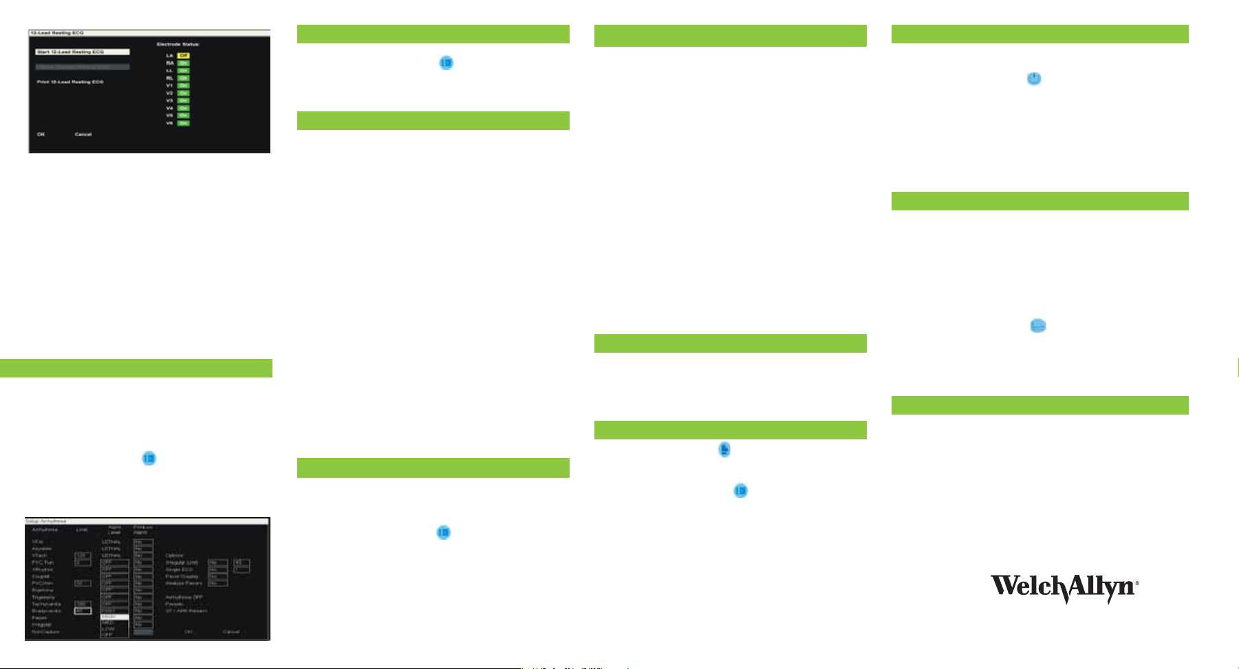
iii. Check electrode status. Ensure the green On is
displayed for all electrodes – this indicates that the
electrode resistance is within acceptable range to
obtain a valid reading.
NOTE: If all appear Off and patient is connected to all their
leads, check the RL and LL. If either of these is not seated
correctly or a signal is not being received from these, all leads
will show off on the device.
iv. Select Start 12-lead Resting ECG. The message Rest
ECG Analysis - in Progress is displayed while the
resting ECG is being taken. This is followed by Rest
ECG - Complete.
v. The resting ECG remains in memory until a new
patient is defined or the ECG is overwritten with a
new recording.
vi. To print the 12-Lead at the device after it has been run
and sent to acuity: select and press the “print 12-lead
resting ECG” option. It will then print at the device.
To Set Arrhythmia Settings
1. The arrhythmia menu entry is only displayed when the full
arrhythmia option is enabled.
2. When the device is connected to Acuity, the Arrhythmia/
ST menus are not available on the device as this is done by
Acuity.
3. To Change Arrhythmia Settings:
a. Press the Setup button
b. Select Arrhythmia
c. Arrhythmia Screen displays. Turn the Trim knob to
highlight desired option and press the Trim knob. Rotate
the knob to make changes and then Press in the knob.
Then press OK.
To Enable ST Analysis
1. To enable ST analysis:
a. Press the Setup button
b. Use the trim knob to highlight and select Parameters.
c. Use the trim knob to highlight and select “Yes”.
d. Use the trim knob to highlight and select OK.
Measuring etCO2
1. If the etCO2 measurement field is not displayed it means that
it is not enabled in the parameter settings.
2. To Enable etCO2
a. Press the Setup button.
b. Use the trim knob to highlight and select Parameters.
c. Use the trim knob to highlight and select “Yes”.
d. Use the trim knob to highlight and select OK.
NOTE: The Oridion sensor is the only approved sensor for
etCO2 monitoring.
3. Preparing the Oridion sensor
a. During nebulization or suction for Intubated patients,
in order to avoid moisture buildup and sampling line
occlusion, remove the sampling line luer connector from
the monitor.
b. Replace the sampling line according to hospital protocol
or when a blockage is indicated by the monitor.
c. When connecting a sampling line to the monitor, screw
the sampling line connecter clockwise into the monitor
CO2 port until it can no longer be turned.
d. When the Caution message “Blockage!” appears on the
screen indicating that the filter line which is attached
to the handheld monitor is blocked, the monitor’s CO2
pump will stop pumping the patient’s breath into the
monitor for testing.
i. Disconnect and reconnect the filter line.
ii. If the message still appears, disconnect and replace
the filter line. Once a working filter line is attached to
the handheld monitor, the pump will automatically
resume operation.
Measuring Respirations
1. The RR measurement field is not displayed if the etCO2
field is active. If the RR is measured via the ECG instead of
etCO2, the etCO2 measurement field must be deactivated as
follows:
a. Press the Setup button
b. Select Parameters
c. Deactivate etCO2 by selecting “No”.
NOTE: The RR signal is measured via the R (RA) and F (LL)
electrodes of the ECG cable (impedance measurement). After
the patient is connected, about 30 seconds can elapse before a
reliable value is displayed.
Measuring Invasive Pressures
1. Changing IBP Settings
a. Select the P1 or P2 measurement field using the trim knob. A
white frame appears around the measurement field.
b. Press the trim knob to display the menu.
c. Scroll down to the desired parameter and press the trim
knob to make changes.
2. IBP Zero Set
a. Zero Set must be carried out before every application.
b. To prevent incorrect measurement readings due to the sensor’s
physical null drift, calibrate the sensor every 24 hours.
c. Move to the desired IBP measurement field (P1, P2) using
the trim knob.
d. Press the trim knob to display the IBP menu.
e. Select Zero Set with the trim knob and press to carry out
the zeroing.
f. The message “P1 Zeroing” appears followed briefly by
“P1 Zero OK”.
NOTE: Carefully read the manufacturer’s instructions before
using the invasive blood pressure kit.
NOTE: When applying the kit to the patient, make sure that
absolutely no air penetrates the system.
NOTE: The kit and operating procedure vary according to
manufacturer. Please consult the manufacturer’s documentation
for connection.
NOTE: P1 is the only connection that can determine the HR/PR source.
Measuring Temperature
1. Depending on the sensor type, the sensor can be applied to
the ear, the skin or to the rectum.
2. To achieve a reliable measured value, independent of the
measuring site, the measurement duration must be at least 2
minutes.
Printing
1. Press the Print Button
2. An auto printout can also be obtained when a limit is
violated. This is also defined in system setup.
3. To change printer option
a. Press the Setup button
b. Use the trim knob to highlight Recorder and push knob
c. Use the trim knob to make changes to the waveform,
recording time, and recording delay.
d. Highlight and select OK.
4. To change printer paper.
a. Pull the locking catch to the front. The paper tray is
unlocked.
b. Pull the paper tray out.
c. Insert paper and pull the beginning of the paper out.
Make sure that the paper mark is facing to the top.
d. Reinsert and close the tray. Be sure that the paper lies
exactly between the rails.
Standby Mode
1. This mode is selected to temporarily interrupt the monitoring of the
patient until ready to resume. All patient data is saved.
2. When the Standby button
“Standby Mode Press any key to resume monitoring” is displayed:
a. In standby mode, vital signs data and alarms are no longer
displayed or collected.
b. When monitoring is resumed, the user is prompted to confirm
the same patient: If no is selected, patient data is deleted.
c. If a patient has not been confirmed, all patient data is lost when
standby mode is entered.
d. When the monitor is connected to Acuity, different options are
given (see above).
is pressed, a black screen with
Reviewing Trends
1. The measured values are entered in the set intervals and
additionally after every manual NIBP measurement. The monitor
can store 24 hours of trends at 1-minute intervals.
2. Trend data is deleted when a new patient is entered.
3. When the memory is full, the oldest trend data is overwritten.
4. The display interval for the table can be selected using the Trend
button.
5. 1 minute, 5 minute, 15 minute, 1 hour, and 4 hour intervals can be
selected.
6. Displaying trend data
a. Press the Trend button
b. Previous measurements are displayed using the up/down icons.
c. Use the trim knob to select the trend display interval with the
pull down menu in the Interval setting.
d. The Clear option deletes all trend data.
e. The Print option prints all displayed trend data.
Cleaning the Monitor
1. To clean the monitor or any accessories, follow these steps:
a. Wipe the equipment with a cloth slightly moistened (not wet)
with one of the approved cleaning solutions; 70% solution
isopropyl alcohol, neutral mild detergent solution, all products
designed for cleaning plastic
2. Thoroughly wipe off any excess cleaning solution. Do not let the
cleaning solution run into or accumulate in connector openings,
latches, or crevices. If liquid gets into connectors, dry the area with
warm air and then check the equipment to confirm that it operates
properly.
NOTE: Never use any of the following solutions or similar products to
clean the equipment: ethyl alcohol, ethanol, acetone, hexane, abrasive
or scouring powder or material, any cleaning material that damages
plastic.
8500 SW Creekside Place • Beaverton, OR 97008
©2010, Welch Allyn, Inc. All rights reserved. MC 8825 09/2011
1-800-289-2501
 Loading...