

Page 1
Weidmüller t
Bedienungsanleitung
Operating instruction
IE-SW14-24-M
managed Switch
Made in Germany
D
IE-SW8-M 8845740000
IE-SW6/2SCS-M 8851850000
IE-SW6/2SC-M 8845840000
IE-SW6/2ST-M 8845850000
IE-SW16-M 8845800000
IE-SW14/2SCS-M 8851860000
IE-SW14/2SC-M 8845780000
IE-SW14/2ST-M 8845790000
IE-SW24-M 8845830000
IE-SW22/2SCS-M 8851870000
IE-SW22/2SC-M 8845810000
IE-SW22/2ST-M 8845820000
Page 2

12
Table of content
Introduction
Specifications
Dimensional Drawing
Segment length
Installation
Connections
Auto-MDIX
LED
Fault Relay
Power options
Management Features
Declaration of conformity
Warranty
Page 3

13
Introduction
With the new IE-SW14-24-M facility we provide up to the 24 Ethernet ports (10/100 BaseT/TX) for
the control cabinet (DIN-Rail).
Many applications need switches in the control cabinet for the distributed construction of industrial
networks. The Switch is a Plug and Play device with ST or SC fiber connections.
The devices can be operated in an ambient temperature range from 0 °C to +60 °C.
Technical details
Case: Solid case of aluminum (IP
20)
Dimensions: 140 x 44 x 156 (in mm)
Input Voltage: DC 10 – 36 V, AC 8-24 V
Input Power: Max. 20 W, power supply
must deliver a minimum of
6 Amps when device is
turned on
Temperature: 0 °C up to +60 °C
LED: Speed / Link/ Activity/
Temperature
Ports: RJ-45 on top and bottom
Fiber ST or SC
2 Fiber / copper
Compatibility: IEEE 802.3x and more
Din-Rail: TS35
Data Rate: 10BaseT/100BaseTX
(Copper) 100BaseFX (Fiber)
PLC: fault relay for PLC support
Segment
Length: Copper 100 m
Fiber (multimode) 2000 m
General
Specifications: 256 Kbyte/ per 8 Port Buffer
4 K MAC addresses per 8
Port
Aging: 300s
Optical Budget: 8 dB
at 62,5µm/125µm MM cable
4 dB
at 50µm/125µm MM cable
13 dB at 9µm/125µm SM
cable
Approval: CE, UL 508, c-UL
Page 4

14
Dimensional Drawing
Page 5

15
Segment Length
10 Base T copper 100 m
100 Base TX copper 100 m
100 Base FX multimode fiber 2000 m Full Duplex
• connector SC and ST
Halb Duplex is not supported
1310 nm/ 62.5/ 125 µm optical budget 8 db
50/ 125 µm optical budget 4 dB
singlemode fiber
• connector SCS 9/ 125 µm cable 13 dB
Installation
The IE-SW14-24-M is for wall mounting and DIN-Rail mounting.
DIN-Rail mounting Taking off the DIN-Rail
Wall mounting
Remove the infolded brackets
Fix the backets out-foulded
Only a qualified technician is allowed to install and operate the Switch.
There must be 25 mm free space on both sides for ventilation to the neighbour
on the DIN-Rail.
Page 6

16
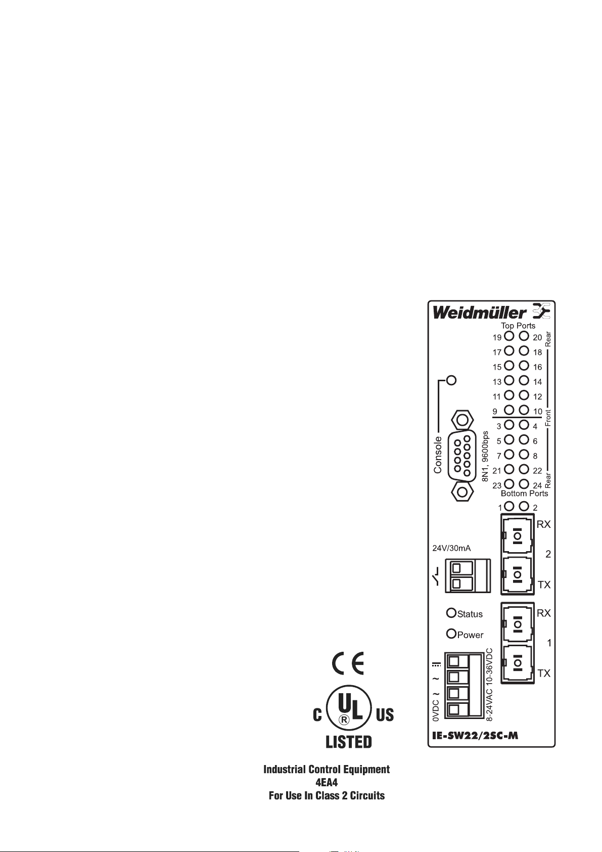
Connections
RRJJ--4455 ccoonnnneeccttoorr
• copper
• segment length up to 100 m
SSCC--ccoonnnneeccttoorr
• Multimode with 1310 nm
• segment length 2000 m
• full compliance with the optical performance requirements
of 100 Base FX
SSTT--ccoonnnneeccttoorr
• Multimode with 1310 nm
• segment length 2000 m
• full compliance with the optical performance requirements
of 100 Base FX
PIN Function
1 TD+
2 TD3 RD+
4 not used
5 not used
6
RD-7 not used
8 not used
Page 7

17
Fault Relay
The error relay can be used to monitor the condition of the switch. If the switch is turned off the
relay contacts are open. When power is being applied the contacts of the relay remain open until
BOTH power inputs have reached a valid level. Only then the contacts are closed. If in the ongoing
opration one of the voltage levels drops below the lower end the relay contacts are opened again. In
case the switch is operated via one power input only a connection between the DC input and ONE
of the AC inputs can be made to simulate the 2nd supply voltage. The relay is rated at 24 V with a
maximum of 30 mA.
LED
Power green power on
red invalid incoming power
LNK / ACT yellow 10 Mbit/s Link
green 100 Mbit/s Link
yellow flashes 10 Mbit/s Link traffic
green flashes 100 Mbit/s Link traffic
Status green no problem
red fault description see handbook
Console green logged in
off logged out
Auto-MDIX
The switch works with AUTO-MDIX functionality. It is possible to use crossover and straight- through
cables to connect network interfaces or other devices with the switch.
Page 8

18
Power Options
In all power schemes a fuse of 4 A slow is required in the power supply lines.
The connection to the power supply should be done by a qualified technician
only.
Use a Class 2 power supply only.
The power supply should be conform to DIN EN 60 742 (VDE 0551)
On the bottom rear end a connection to functional earth is recommended. This
connection is recommended by a 4 mm² cable with a 6.3 female spade termi
nal, the IE-SW14 to 24-M Line has the male spade terminal.
The IE-SW-14 to 24-M Switch does NOT charge
the battery, so separate provisions charching are
required.
Page 9

19
Declaration of Conformity
Applied Council Directives:
Electromagnetic Compatibility Directive, 89/336/EEC Council Directive as amended by Council
Directive 92/31/EEC & Council Directive 93/68/EEC
General Product Safety Directive 92/59/EEC
Standard to which Conformity is declared
EN 55022:1995, Class A, Limits and Methods of Measurement of Radio Disturbance
Characteristics of Information Technology Equipment
EN 55024:1998, Information Technology Equipment – Immunity Characteristics –
Limits and Methods of Measurement.
Management- Features
• SNMP V1
• Proprietary Redundancy
• 802.1Q VLAN
• Port based VLAN
• Port based QoS
• MAC based Trunking
• Port setup functionality
• Port mirroring
• Performance Monitoring
• Fault relay
• Serial interface for extensive setup
• Capabilities (menu driven)
• Ring Redundancy
Warranty for this Product
Weidmüller gives a 2 year warranty on all its actively processing Industrial Ethernet products and all
actively processing I/O-Interface products in accordance with the warranty terms as described in the
general conditions of sale of the Weidmüller company which has sold the products to you.
In addition to the 2 year warranty, Weidmüller warrants to you for a period of 3 additional years that
such products the defects of which have already existed at the time when the risk passed will be
repaired by Weidmüller free of charge or that Weidmüller will provide a new, functionally equivalent
product to replace the defective one.
The warranty referred to above covers Weidmüller products. Safe where expressively described
otherwise in writing in this catalogue/product description, Weidmüller gives no warranty or guarantee
as to the interoperability in specific systems or as to the fitness for any particular purpose. To the
extent permitted by law, any claims for damages and reimbursement of expenses, based on whatever legal reason, including contract or tort, shall be excluded. Where not expressively stated otherwise in this warranty, the general conditions of purchase and the expressive liability commitments therein of the respective Weidmüller company which has sold the products to you shall be applicable.
Manufacturer:
Weidmüller Interface GmbH & Co. KG
Klingenbergstraße 16
32758 Detmold
Germany
Page 10

3
NNoo wwaarrrraannttyy..
The technical documentation is supplied without any warranty of fitness. Weidmüller
does not warrant for their accuracy. The documentation may contain technical and typographical
inaccuracies. Weidmüller reserves the right to change it without notice.
KKeeiinnee GGeewwäähhrrlleeiissttuunngg..
Die technische Dokumentation wird ohne Mängelgewähr geliefert und
Weidmüller übernimmt keine Gewährleistung für deren Genauigkeit. Die Dokumentation kann technische oder andere Ungenauigkeiten und typografische Fehler enthalten. Weidmüller behält sich das
Recht vor, Änderungen ohne vorherige Ankündigung vorzunehmen.
All rights reserved. Reproduction, copying, or redistribution for commercial purpose of any
Weidmüller material or design elements is strictly prohibited.
Alle Rechte vorbehalten. Nachdruck und Vervielfältigung der Texte und Graphiken einschließlich
Speicherung und Nutzung auf optischen und elektronischen Datenträgern nur mit Zustimmung der
Weidmüller GmbH & Co. KG. Die ganze oder teilweise Verwertung des Materials durch unberechtigte
Dritte ist untersagt.
Copyright © 2006
Weidmüller t
 Loading...