

Page 1

de
Bedienungsanleitung
Zähler und Totaliser mit Zusatzfunktionen und Grenzwertüberwachung 3
en
Operating instructions
Counter and totaliser with auxiliary
functions and threshold monitoring 24
PTX800D 61001050/00/01.08
Page 2

en
PTX800D
Contents
Operation 25
Setup options 27
Setup Sequence 31
Installation 34
Modifications
Output calibration 40
39
24
Page 3
en
PTX800D
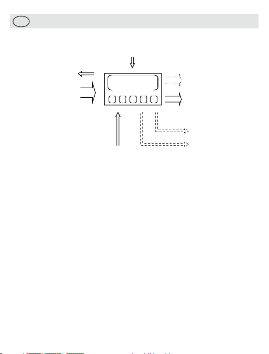
Analogue output
(gives rate or total)
Pulse Output
Pulse Input
Total or
Rate Display
Power for Input device
Reset Pulse Input
Alarm 2
Power
Supply
Alarm 1
PTX800D
• Operation
General
The PTX800D is a scalable pulse counter/rate indicator for digital pulse
signals. It will display either the rate or total according to setup. The
other value is displayed when you hold down the TOTAL/RATE key.
For more complex applications, the PTX800D can be supplied with
two alarm channels and/or an analogue retransmit output.
Alarm conditions are indicated by the LEDs above buttons marked AL1
(for alarm channel one) and AL2 (for alarm channel two).
Manually clearing tripped alarms
The alarm channels can be set for automatic or manual reset. For
manual reset, the LED will flash when an alarm trips. These alarms will
only clear if you have acknowledged the alarm and the trip condition
has cleared. Press AL1 or AL2 to acknowledge the alarm.
25
Page 4

Viewing the alarm setpoints
Press the AL1 or AL2 at any time to display the setpoint for that
channel. The value will be shown for 5 s. If the alarms are disabled,
pressing the key will have no effect.
Changing the alarm setpoints
Press PGM while the setpoint is on display (see above), you will be able
to change the value using the ì and Å keys. To save the changes,
press PGM. Note: you can disable this feature during setup for greater
security.
Checking the Rate/Total
You can set up the PTX800D to show either total or rate. If the total
is normally on display, you can check the rate by holding down the
TOTAL/RATE key.
Reseting the total
If you press the RESET key, the PTX800D will set the total to zero and
clear any total alarms (you can disable this feature during setup for
greater security). There is also an external reset input that you can use
to clear the total remotely.
Reviewing the setup options
To review the setup (in read only mode) press the PGM key. The
PTX800D will show the software version number. Press the Å key to
see the next setting. The information in review mode is shown in the
same order as setup mode (some irrelevant items will be skipped).
There is a 10 s timeout during review mode or you can press PGM
again to return the display to normal operation.
You can review the setup while the instrument is in service - the unit
will continue to operate normally. Setup mode
26
Page 5

Changing the setup options
You should only use setup mode if you have to change a setting or
calibrate the outputs. The setup mode stops all operation. As soon as
you have setup the last parameter, the unit behaves as if it has been
switched on with the new settings. This does not mean that the total is
reset - you must do this yourself if necessary.
If you want to abandon all the changes you have made, simply remove
the security link (or remove the power) before the save message is
shown.
To change the instrument setup:
. Con
nect the security link (short pins 8 & 12).
1
2. Press the
The setup sequence is shown in the table on page two.
PGM key.
• Setup options
General
There are four basic areas of the instrument operation that must be
setup on a fully configured PTX800D. They are:
e/frequency inputs;
• Puls
• Display and keypad operation;
• Alarms one and two (optional); and
• Analogue outputs (optional).
You can disable the alarms and/or analogue outputs if you do not need
them (so that their settings are skipped).
Software version
The information in this guide refers to versions 1.00 to 1.09.
Model
PTX series instruments all look identical from the front so this identifies
the intrument type.
27
Page 6
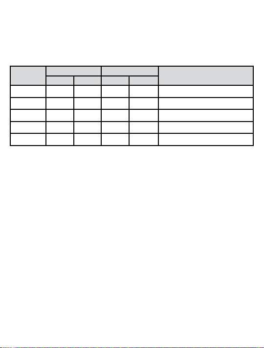
Input signal type
Sets the input trigger and reset levels to suit the pulse source. The
table below gives the threshold values.
For contact closure inputs, the software incorporates debouncing
min
imum pulse width 20 mS / maximum frequency 10 Hz).
(
Input type
LOAC
HIAC
LOdC
HIdC
CoN
Low volta ge inputs High vo ltage inputs
Trigger Rese t Trigger Rese t
50 mV -50 mV 200 mV -40 0 mV Low level AC sign als
2.5 V -2.5 V 14 V -10 V High level A C signals
3.5 V 0.5 V 20 V -2 V Low level DC signals
6 V 3 V 35 V 10 V High l evel DC signals
6 V 3 V 35 V 10 V Contact clos ure
Desc ription
Pulse rate
Set the pulse rate to low if the maximum input frequency is below
z. Otherwise it should be set to high.
1 kH
Pulse scaling factor
Sets the number of pulses received for a unit change in the total. So, if
you have a flowmeter that gives four pulses per litre, you can show the
total in litres by setting the pulse scaling factor to four, or in kilolitres by
setting the pulse scaling factor to four thousand. You can not set it to
more than 10 000 display digits (i.e., ignoring the decimal point).
Total decimal point
The total decimal point position sets the number of decimal places for
the total display. Totals are displayed using the full eight digits.
Rate decimal point
Sets the number of decimal places for the rate display. Rates are
displayed as five digit numbers.
28
Page 7

Rate scaling factor
The rate scaling factor sets the ratio between the total display and the
rate display. It must be a power of ten (i.e., 1000, 100, ..., 0.01, or 0.001).
Number of samples
X800D calculates the rate every 260 mS. The analogue output
The PT
and display are then updated from the average over the programmed
number of samples. For example, if you set the number of samples to
e analogue output and rate display will be updated every 2.6 s.
10, th
Rate timebase
The rate timebase setting sets the timebase for the rate display. It can
be set to hours, minutes or seconds.
Show rate or total
Use the display rate/total setting to choose the measurement that will
normally be on display.
Enable Reset key
The front panel reset key can be used to reset the total. You can
disable this feature (for added security) using this setting.
Alarms disable/enable
If you do not need alarms, you can disable them. This simplifies the
setup process, as all of the parameters related to the alarm operation
are skipped.
Alarm type
Each alarm channel can monitor the total or the rate. Total alarms
operate when the setpoint is exceeded. A ‘total’ alarm trip condition
clears when the total is reset.
Setpoint
The setpoint is the display value at which an alarm activates. It can be
changed during normal operation if the setpoint security option is off.
29
Page 8

Alarm action
High alarms are active above the setpoint and low alarms are active
below the setpoint. Total alarms are always ‘high’ type, so this setting
is not shown.
Deadband
This parameter sets the “hysteresis” for an alarm channel; the alarm will
clear above or below the setpoint to prevent chatter when the rate level
passes the setpoint. The minimum deadband is one display count.
Total alarms do not need a deadband setting.
Alarm output energisation options
There are many applications where it is important to raise an alarm
if the instrument power supply is cut off. Normally energised coil
operation allows for this application.
Alarm timer delays
Sets the minimum time that an alarm condition must be present to be
recognised.
Setpoint security
You can change the setpoints from the front panel. If you want to
disable this feature, switch on the setpoint security.
Alarm reset sequence
Alarms normally reset automatically when a trip condition has passed.
Manual reset requires the operator to press the appropriate key before
the alarm will clear. The alarm status LED flashes until the alarm is
acknowledged and then remains on until the trip condition is gone.
Total or rate output and range
To set up the analogue outputs you must first choose if the output is
going to be proportional to the rate or the total. After that you can set
up the portion of the rate/total range that you want to retransmit.
30
Page 9

Analogue output format
These setup parameters let the PTX800D show the output range
correctly during review mode and prompt for the correct values during
calibration. They have no affect on the operation of the instrument. If
you change them you must be prepared to calibrate the outputs.
Output Action
Direct action results in the normal, proportional output. Reverse action
gives an output that is inverted with respect to the rate, so a rate of
zero gives a full scale output and vice versa.
Display Intensity
There are fourteen different levels.
• Setup Sequence
Sett ing Display Descript ion
S/ W Version
Model
Inputs
Input type
Input puls e rate
Pulse scaling
fact or
vEr_1.01
Pulse
IP=
LOdC
HIdC
LOaC
HIAC
Con
Freq=_LO
Freq=_HI
Pulse_dp=
123.45
PulSE_SF=
1.230
S/ W Version 1.01 - - Next
Pulse coun ter: PT X800D - - Next
Intr oduces the inpu t type - Next
Low le vel DC
High level D C
Low le vel AC
High level A C
Cont act closure (deboun ced)
Low frequency input (below 1 kHz)
High f requency i nput (from 1 to 10 kHz)
Pulse scaling facto r decimal point
Demo display for decim al point select ion-Shif t-Shif t
Intr oduces the puls e scaling f actor
e.g., 1. 230 Pulse = 1 Unit change in tot al- Dec- Inc
Å ì
PGM
Toggle Accept
Toggle Accept
Next
Accept
Next
Accept
31
Page 10

Setup Sequence (continued)
Total and rate display set tings and scaling
Total decima l
point
Rate decimal
point
Rate scaling
fact or
Rate timeb ase
Numbe r of
sampl es
Show r ate or
tota l
Reset key enable
Rese t Total Key
Enable
Alarm enable
Alar ms 1 & 2
Select
Alarm channel one set tings
Coil energ isation
Alar m one type
Alar m one
action
Setp oint value
Deadb and
value
Timer delay
Alarm channel two setting s
As ab ove
tot_dp=
1234.5
tot_dp=
12.345
rATE=_SF=
1000
rate_SEC
rate_min
rate_Hr
SAmp=
dis=rate
dis=tot
En_resY
En_resn
A12Y
A12n
A1_nor_E
A1_nor_d
A1=_rate
A1=_tot_
A1=_LO
A1=_HI
Set_Pt1=
50.00
dband_1=
0.01
delay_1=
As channel one (except uses A2_no r_E, A2=_r ate,..., del ay_2=)
Intr oduces total decima l point
Demo, e.g., tota l shown to o ne decimal p lace-Shif t-Shif t
Intr oduces rate decimal point
Demo, e.g., rate shown to 3 decima l places-Shif t-Shif t
Intr oduces rate scaling factor
e.g., 10 00 rate units = 1 total unit
Rate is in units per second
Rate is in units per minute
Rate is in units per ho ur
Intr oduces the number of s amples use d for
rate, e.g., 10
10
Display normally sho ws the rate
Display normally sho ws the total
RESET key rese ts count
RESET key ignored
Enable
Disable (Select this option for PMX420)
Normally e nergised
Normally d e-energi sed
Channel on e monitors tot al
Channel on e monitors rate
Low t ype (active below setpoint)
High t ype (acti ve above setpoint)
Setp oint value
e.g., 5 0.00 %
Deadb and value
e.g., 0 .01 %
Timer delay (set to 0 s to disable)
e.g., 2 0 s
20
-
Dec- Inc
Toggle Accept
-
Dec- Inc
Toggle Accept
Toggle Accept
Toggle Accept
Toggle Accept
Toggle Accept
Toggle Accept
-
Dec- Inc
-
Dec- Inc
-
Dec- Inc
Next
Accept
Next
Accept
Next
Accept
Next
Accept
Next
Accept
Next
Accept
Next
Accept
32
Page 11

Setup Sequence (continued)
Gener al alarm settings
Setp oint
secur ity
Alar m reset
seque nce
Analogue output set tings (not shown unless outp uts are fitted)
Rate or total
output
Rate range
repre sented
Total r ange
repre sented
Outp ut type
Outp ut range
Outp ut Action
Calibr ation options
Calibrate
Outp ut?
Display
Intensit y
Save values
SECure_y
SECure_n
reS_Auto
rES_Oper
Out=rate
Out=_tot
rate_LO=
0.00
rate_HI=
100.00
tot_LO=
0.00
tot_HI=
100.00
Out=_Cur
Out=volt
Out_LO=
4.00
Out_HI=
20.00
Out_dir
Out_rev
CalOut_n
CalOut_y
Intens_=
234567.89
SAVE
Setp oints fixed at setup
Can change setpoints
Auto matic reset
Manual reset
Anal ogue output propor tional to rate
Anal ogue output propor tional to total
Intr oduces the rate low value
e.g., 0 .00
Intr oduces the rate high value
e.g., 10 0.00
Intr oduces the rate low value
e.g., 0 .00
Intr oduces the rate high value
e.g., 10 0.00
Current (m A) outpu t
Voltage ( V) output
Intr oduces output low va lue
Value, e.g., 4.00 mA
Intr oduces output high value
Value, e.g., 20.00 mA
Direct (propo rtional ) output
Rever sed (inverted) output
Skip output calibration
Calibrate outputs
Intr oduces the disp lay intensity
Demo display for adjus tment
Inst rument is s aving the changes to t he setup and ret urning to
normal ope ration
Toggle Accept
Toggle Accept
Toggle Accept
-
Dec- Inc
-
Dec- Inc
-
Dec- Inc
-
Dec- Inc
Toggle Accept
-
Dec- Inc
-
Dec- Inc
Toggle Accept
Toggle Accept
-
Dec- Inc
Next
Accept
Next
Accept
Next
Accept
Next
Accept
Next
Accept
Next
Accept
Next
Accept
33
Page 12

Installation
Caution: In order to meet product safety requirements, these units
must only be installed, by qualified staff, in accordance with the
information given in this manual, using the mounting clips and terminal
blocks supplied, and all relevant national electrical wiring and safety
rules must be followed.
Locate the instrument in an area that is free from dust, moisture
and corrosive gases (pollution degree II or better). Do not cover the
ventilation holes at the side of the case.
Power Supply Requirements
PTX800A displays must be used with a suitable mains Power Supply,
ratings are as follows:
Voltage Range Nomin al Voltage Power Frequency
100–132 V AC 110 V AC 6 VA 47-63 Hz
200 –264 V A C 240 V A C 6 VA 47-63 Hz
21.6–26.4 V DC * 24 V DC 6 W (at 24 V DC) -
*Using a DC power supply that provides this voltage will comply with
the instrument’s cULus listing, file number: E256486.
Input connections
The input circuit has programmable trigger levels according to the
‘Input type’ setting.
MUR sensors, 3-wire NPN sensors, 3-wire PNP sensors, NPN
For NA
open collector (O/C) outputs and PNP open collector (O/C) outputs set
the input type to “High Level DC” (HIdC ).
For voltfree contact inputs use ‘Contact closure’ (Con). The minimum
ont
act closure time is 20 mS and the maximum frequency is 10 Hz.
c
For voltage pulses (including TTL/CMOS logic) select a suitable input
type using the trigger/reset voltage table.
34
Page 13

Input voltages over 45 V DC
If the input voltage is above 45 V DC connect the internal high voltage
select jumper before applying the signal (maximum voltage is
250 V DC).
igital pulse output
D
The basic model PTX800D has a retransmit pulse output, which gives
a single pulse every time the total increases by one unit. The pulse
h is a constant 32 ms and the minimum off time is 32 ms. The
widt
output is an isolated, NPN, open collector transistor type and can
switch a maximum of 50 V DC or a current up to 200 mA.
Reset pulse input
pts a volt-free contact closure, or a shorting link, between pins 7
Acce
and 12. The contact must be closed for at least 100 ms.
Alarm channels one and two (optional)
Alarm channels one and two have SPDT relay contact outputs. The
rated current decreases for inductive loads so using suppressor
capacitors is recommended.
Analogue output (optional)
The analogue output provides you with a current or voltage based
signal that is proportional to the rate or total. For rate outputs, the
average value is the same as the rate, although the instantaneous
value may differ slightly for rapidly changing signals.
35
Page 14

Connections
For effective protection from electromagnetic noise, all signal cables
must be shielded, or located on conductive trays or in conduits.
p wires to 7 mm from the ends. Use a suitable ferrule for
Stri
multistranded wires (do not solder).
Pin Signal
1 N eutral / –
2 L ive / +
3 S ignal +
4 S ignal –
5 0 V
6 P ulse
7 R eset count Shor t to 12 to res et
8 S ecurity Shor t to 12 for se tup mode
9 P ull Up/Down
10 I
nput – / 0 V
11 I
nput +
12 +12 V DC (out)
13 Normally Closed
14 Common
15 Normally Open
16 Normally Closed
17 Common
18 Normally Open
Power supply
Anal ogue output (op tional)
Pulse output
Inputs
Alar m one
(optional )
Alar m two
(optional )
Input signals
The PTX800D input circuits are rated category II (suitable for
measurements performed on the low voltage installation). They may
safely be floating with respect to local ground (i.e., subject to common
oltages) up to 250 V DC.
mode v
36
Page 15

PTX800 analogue output board showing output type jumper locations.
Link both pairs
of posts for
voltage outputs
Symbols
The instrument labels use symbols in accordance with IEC61010-1:
- Consult documentation; - Direct Current; - Double
Insulated.
37
Page 16

NAMUR
sensor
–
PTX800D
10+ 129 11
For NAMUR sensor
nputs.
NPN typ e
3-wire sensor
(O/C out puts)
Sig–
PTX800D
9+ 10
Power (+ve)
Signal
Power ( –ve)
11 12
For 3-w re sensors
w th NPN open
co ector ouputs
PNP type
3-wire sensor
(O/C outputs)
Sig–
PTX800D
9 12+ 10
Power (+ve)
Signal
Power ( –ve)
11
For 3-w re sensors
w th PNP open
co ector outputs
Sensor
PTX800D
9– 12Sig 1110
For externa y powered
NPN open co ector
sensor nputs
Sensor
PTX800D
10+ 12Sig 9 11
For exter na y p owered
PNP open co ector
sensor nputs
Vo tage pulse
source
PTX800D
10- 11+
For vo tage
pu se npu ts.
Volt-free
contacts
PTX800D
ba 10 129 11
For vo t-free
contact nputs.
Input type
Low voltage inputs High voltage inputs
Description
Trigger Reset Trigger Reset
LOAC 50 m -50 m 200 mV -400 mV Low level AC signals
2.5 V -2.5 V 14 V -10 V High level AC signals
3.5 V 0.5 V 20 V -2 V Low level DC signals
6 V 3 V 35 V 10 V High level DC signals
6 V 3 V 35 V 10 V Contact closure
HIAC
LOdC
HIdC
CoN
Input Types
38
Page 17

• Modifications
Analogue output type
The analogue output type (current/voltage) is set by internal push fit
jumper. To change the output type:
Change the output type push fit jumper:
1. Gently remove the backplate (it is held in place by four lugs).
e the electronics from the housing.
lid
2. S
3. Change the jumper location to the required setting (see diagram
above).
4. Loo
k inside the housing and note that there are connectors that
mate with the display board.
ide the electronics gently back into the case. Carefully moving the
5. Sl
board until the keypad connectors engage with the display board.
lace the backplate.
6. Rep
Change the output type in the software:
1. Power up the instrument and start the setup routine.
le the software version number is flashing, remove the security
2. Whi
link and press PGM.
isplay will show Ao ut_=_y. Press PGM.
3. The d
isplay will show Ao ut=volt or Ao ut=_cur. Select using up
4. The d
or down key.
5. Replace the security link and press PGM.
Change the output range settings:
oll through the setup and change the output type and range
Scr
6.
settings - you will be required to calibrate the outputs.
Calibrate the output:
ali
brate the outputs to the new output range and type.
7. C
39
Page 18

High/Low voltage input selection
1. Gently remove the backplate (it is held in place by four lugs).
e the electronics from the housing.
2. Slid
3. Change the High/Low voltage jumper to the required setting (see
diagram right).
4. Loo
k inside the housing and note that there are connectors that
mate with the display board.
ide the electronics gently back into the case. Carefully moving the
5. Sl
board until the keypad connectors engage with the display board.
6. Replace the backplate.
Output calibration
General
The PTX800D analogue outputs are calibrated for a specific output
range and type. If you have changed the output range or type you
must follow the procedure given below.
Allow the instrument 15 minutes of powered operation (to reach a
stable temperature) before calibrating the output.
Equipment requirements
• An accurate digital multimeter (accurate to 0.05 mV and ±0.1 μA)
Terminal Connections for output calibration
Calibr ation Stage Signal t ype Terminal
Anal ogue Current Outpu t
Anal ogue Voltage Ou tput
mA ou tput + 3
mA ou tput – 4
V output + 3
V output – 4
40
Page 19

Procedure
Note: the procedure below shows calibration for the commonly used
4-20 mA f
ormat. If you have set the outputs to any other format, the
unit will prompt you with the output high and low values you have
chosen.
When th e
display shows
Put the ins trument in setup mode and scroll through the main menu
CALOut_n
CAlOut_y
Out_LO_=
4.00
Out_HI_=
20.00
Save
Note: Do not rem ove the power while the save m essage is on dis play.
Action/Description
Pres s ì or Å
Pres s PGM to select output calibration
Connect t he multimeter to meas ure the output level, then pres s PGM
Pres s PGM
Meas ure the out put signal
Adjust the output (u sing the ì o r Å keys) unt il the output is at the valu e shown
When you ar e happy that the output is c orrect, pres s PGM
Pres s PGM
Pres s PGM
Meas ure the out put signal
Adjust the output (u sing the ì o r Å keys) unt il the output is at the valu e shown
When you ar e happy that the output is c orrect, pres s PGM
Cont inue with t he setup sequence.
41
Page 20

Analogue
Output
Board
Link these
pins for
High input
voltages
Link these
pins for
Normal input
voltages
Display Board
Main Board
96 6 mm
137 00 mm
PANEL THICKNESS Max 18 0mm
48.8 mm
44.7 mm
96.6 mm
60.0 mm
143 5 mm
5.5 mm
15 5 mm
PGM
EN
T
18 0 mm
GASKET
92 0 mm (+0 8 / 0 0 mm)
CUTOUT
45.0 mm (+0.6 / -0.0 mm)
PGM
EN
TOTAL
RATE
AL1
AL2
Front panel is rated IP65 when
correctly Installed in panel
Temperature range: 0-60 °C
Altitude: < 2000 m
Relative humidity: 0-95 %
(non-condensing)
Dimensions
42
Page 21

43
Page 22

Weidmüller Interface GmbH & Co. KG
Postfach 3030
32720 Detmold
Klingenbergstraße 16
32758 De
Tel. +49 5231 14-0
Fax +49 5231 14-20 83
info@weidmueller.com
www.
tmold
weidmueller.com 61001050/00/01.08
 Loading...