

Page 1

de
Buy: www.ValinOnline.com | Phone 844-385-3099 | Email: CustomerService@valin.com
Bedienungsanleitung
4-stellige Strom-/Spannungsanzeige 3
en
Operating instructions
4-digit current/voltage display 16
fr
Mode d'emploi
Indicateur de courant/
tension à 4 caractères 27
it
Istruzioni per l'uso
Indicatore di corrente/
di tensione a 4 cifre 40
es
Instrucciones de empleo
Indicador de intensidad/
tensión de 4 dígitos 52
PMX420-SERIE 61001099/00/01.08
Page 2

en
Buy: www.ValinOnline.com | Phone 844-385-3099 | Email: CustomerService@valin.com
PMX420 SERIES
Inhaltsverzeichnis
Operation 17
Installation 19
Connections 20
Instrument Setup 22
Input Calibration 24
Page 3
en
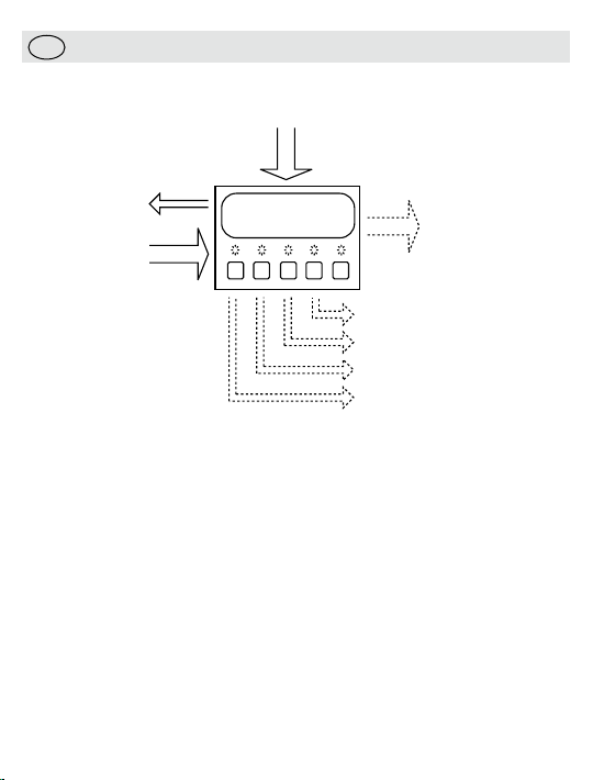
Current/Voltage
Analogue Output
(PMX420 Plus Only)
Alarm 3
Alarm 4
Alarm 1
Alarm 2
(PMX420 Plus Only)
Power
Supply
Engineering Units
24Vdc (Out)
Buy: www.ValinOnline.com | Phone 844-385-3099 | Email: CustomerService@valin.com
PMX420 SERIES
• Operation
The PMX420 is a panel mount, digit indicator for current or voltage
signals. It shows the input measurement in any chosen engineering
unit using bright, 14 mm high, LED digits. The PMXPlus is fitted
with four alarm channels and analogue output for more complex
applications.
Reviewing the setup
For review mode, press the PGM and ENT keys simultaneously.
Press the Å key to move through the setup sequence (see table).
Greyed items are not shown in review mode.
Note: A 10 s timeout applies for review mode.
Page 4

Maximum/Minimum recall function
Buy: www.ValinOnline.com | Phone 844-385-3099 | Email: CustomerService@valin.com
PGM and Å recalls the minimum value for 5 s. PGM and ì re
calls the
minimum value for 5 s. Release the PGM key first for reliable operation.
To reset either value press ENT while it is still on display.
Clearing
tripped alarms
You can acknowledge a tripped alarm by simply pressing the key for
that channel.
d Group alarms
Siren an
Channel four has two additional alarm types:
• Siren al
arm, which you clear by acknowledging all tripped alarms
• Group alarm, which will only clear when you have acknowledged
and
all tripped alarms
all the trip conditions have cleared (and are
outside the deadband)
Displaying the alarm setpoints
To check a setpoint, simply press the key for that alarm.
If the display shows A4=S or A4=g when you press the alarm channel
four button, you know it is set up as a siren or group alarm.
djustin
g the alarm setpoints
A
To change a setpoint, press the PGM key while the value is still on
display. You will then be able to change the value using the arrows and
save the change using the ENT key. Note that setpoint security must
disabled for this to work.
Page 5

• Installation
Buy: www.ValinOnline.com | Phone 844-385-3099 | Email: CustomerService@valin.com
Caution: In order to meet product safety requirements, these units
must only be installed, by qualified staff, in accordance with the
information given in this manual, using the mounting clips and terminal
blocks supplied, and all relevant national electrical wiring and safety
rules must be followed.
Locate the instrument in an area that is free from dust, moisture and
corrosive gases. Do not cover the ventilation holes at the side of the
case.
ower supply
Sensor p
The 0 V rail of the 24 V DC sensor supply is internally connected to the
input circuit 0 V rail.
gnal cable
Input si
Twisted pair cable should be used for the input signals. Voltage signals
need the additional protection of shielded cable if used over any
distance.
Power Su
Check the power supply against the model number before applying
power to the instrument.
Connections
For effective protection from electromagnetic noise, all signal cables
must be shielded, or located on conductive trays or in conduits.
U
tighten to 4.5 lb-In. Strip wires to 7 mm from the ends. Use a suitable
ferrule for multistranded wires (do not solder).
pply Requirements
se 12-28 AWG Cu Wir
e rated for temperatures above 70 °C Only,
Page 6

• Connections
Buy: www.ValinOnline.com | Phone 844-385-3099 | Email: CustomerService@valin.com
Terminal S ignal
1
2
3 L
4 Neut ral (−)
5 Sensor supply + / Securit y Link
6 Security Link
7 V
8 Current Input +
9 I
10 Not connected
11 Normally O pen
12 Common
13 Normally C losed
14 Normally O pen
15 Common
16 Normally C losed
17 Normally O pen
18 Common
19 Normally O pen
20 Common
21 O
22 Outp ut −
Not U sed
ive (+)
oltage
nput −
utpu t +
Input +
/ 0 V
Low vo ltage
power suppl y
Inputs
Alar m Channel O ne
(PM X420Plus onl y)
Alar m Channel Two
(PM X420Plus onl y)
Alar m Channel T hree
(PM X420Plus onl y)
Alar m Channel F our
(PM X420Plus onl y)
Anal ogue output
(PM X420Plus onl y)
12-50 V AC or
18-35 V DC
Page 7

+ -
Other
receiving
device/s
PMX420AP
(current inputs)
85
- +
Device with
voltage outputs
PMX420AP
(voltage inputs)
9 7
-+
2-wire
(loop powered)
Transmitter
-+
Other
receiving
device/s
PMX420AP
(current inputs)
98
-+
Device with
current outputs
Typical Connections
Buy: www.ValinOnline.com | Phone 844-385-3099 | Email: CustomerService@valin.com
Page 8

• Instrument Setup
Buy: www.ValinOnline.com | Phone 844-385-3099 | Email: CustomerService@valin.com
For setup mode, connect the security link and press PGM and ENT keys
simultaneously. The software version will be displayed. If you wish to
continue, press ENT within 10 s.
Sett ing Display Description
S/ W Version
Display and Inpu ts
Display
Brightness
Input format
Dampi ng factor
Linearisation
Display range
Analogue outputs*
Anal ogue output
selec t
Anal ogue output
range
Note: if you chan ge the output range you mus t calibrate the outp uts.
Outp ut action
S/ W Version 1.01 (N ote: this i nformati on only app lies to versions
v1.01
1.00 to 1.09)
Low bright ness
LOBr
High b rightnes s
HIBr
Current (m A)
IP=1
Voltage ( V)
IP=E
IPL=
IPH=
20.00
LInr
dLO=
dHI=
100.0
AOPY
AOPN
OPL=
OPH=
20.00
OP=d
OP=r
Input range lower limi t
e.g., 4 .00 mA
4.00
Input range upper limi t
e.g., 2 0.00 mA
Intr oduces the damping fa ctor
dF=
Value, e.g., 2
2
Linear
Square root
Sr
dP=
Decimal point po sition
.
Display range lo wer limit
e.g., 0 .0
0.0
Display range Upper limit
e.g., 10 0.0
Enabled
Disabled ( Select th is option for PMX420)
Outp ut low value
e.g., 4 .00
4.00
Outp ut high value
e.g., 2 0.00
Direct
Rever sed
Å ì
Toggle Accept
Toggle Accept
-
Dec- Inc
-
Dec- Inc
-
Dec- Inc
Toggle Accept
-
Dec- Inc
-
Dec- Inc
Toggle Accept
-
Dec- Inc
-
Dec- Inc
Toggle Accept
Shif t
ENT
Next
Accept
Next
Accept
Next
Accept
-
Next
Accept
Next
Accept
Next
Accept
Next
Accept
Next
Accept
Page 9

Instrument Setup (continued)
Buy: www.ValinOnline.com | Phone 844-385-3099 | Email: CustomerService@valin.com
Gener al Alarm settings*
Alar ms 1 & 2
Select
Alar ms 3 & 4
Select
Setp oint
secur ity
Alar m reset
seque nce
Note: alar m settings are only s hown if the relevant alarm channel is enabled.
annel one settings*
Alarm ch
Coil energisat ion
Alar m type
Setp oint value
Deadb and value
Timer delay
Alarm channel t wo settings*
As alarm ch annel one, except uses A2nE, A2nd, A 2=L,A2=H, SP2=, db 2= and dL2=.
annel three se ttings*
Alarm ch
As alarm ch annel one, except uses A3nE, A3nd, A3= L,A3=H, SP 3=, db3= and dL 3=.
annel four set tings*
Alarm ch
Coil energisat ion
Alar m type
Note: for group or siren ala rms, the setpoint, deadband and timer set tings are skip ped
Setp oint value
Deadb and value
Enable
A12Y
Disable (S elect thi s option for PM X420)
A12n
Enable
A34Y
Disable (S elect thi s option for PM X420)
A34n
Setp oints fixed at se tup
SECy
Can change setp oints
SECn
Auto matic reset
nOr
Manual res et
rES
Normally e nergised
A1nE
Normally de-en ergised
A1nd
Low t ype (active below set point)
A1=L
High t ype (acti ve above setpoint)
A1=H
Setp oint value
SP1=
e.g., 5 0.00 %
50.00
Deadb and value
db1=
e.g., 0 .01 %
0.01
Timer delay (set t o 0 s to disable)
dL1=
e.g., 2 0 s
20
Normally e nergised
A4nE
Normally de-en ergised
A4nd
Low t ype (active below set point)
A4=L
High t ype (acti ve above setpoint)
A4=H
Group alar m
A4=G
Siren alarm (manual reset mode only)
A4=S
Setp oint value
SP1=
e.g., 5 0.00 %
50.00
Deadb and value
db1=
e.g., 10 %
10.00
Toggle Accept
Toggle Accept
Toggle Accept
Toggle Accept
Toggle Accept
Toggle Accept
-
Dec- Inc
-
Dec- Inc
-
Dec- Inc
Toggle Accept
Toggle Accept
-
Dec- Inc
-
Dec- Inc
Next
Accept
Next
Accept
Next
Accept
Next
Accept
Next
Accept
Page 10

Instrument Setup (continued)
Buy: www.ValinOnline.com | Phone 844-385-3099 | Email: CustomerService@valin.com
Timer delay (set t o 0 s to disable)
Timer delay
Calibration options
Calibrate
Input?
Calibrate
Outp ut?
Save values
*Note: Alarms and A nalogue ou tputs are fitted to the P MX420P lus only. You c an still se t values fo r the
alarms and analo gue outpu t on the PM X420 but t hey will onl y affect the di splay and s tatus led s.
dL1=
e.g., n o delay
0
Skip input calib ration
CIPn
Calibrate inputs
CIPy
Skip output calibra tion
COPn
Calibrate outputs
COPy
Inst rument is s aving the change s to the setup an d returning to normal
SAVE
operation
-
Dec- Inc
Toggle Accept
Toggle Accept
Next
Accept
During setup the Å and ì keys change values and toggle options.
The ENT key accepts changes and moves to the next item in the setup
sequence (see table).
Note: if you remove the security link during the setup sequence, any
changes you have made will not be saved.
• Input Calibration
General
The PMX420 series instruments are factory calibrated. You can change
the input range without calibration, but the outputs are calibrated for
the specific range given during the setup procedure.
Equipmen
• A suitable current or voltage source
Terminal
t requirements
Connections for input calibration
Calibr ation Stage Signal t ype Terminal
Current (m A) inputs
Voltage ( V) inputs
Milliamp so urce (+) 8
Milliamp so urce (−) 9
Voltage so urce (+) 7
Voltage so urce (−) 9
Page 11

Procedure
Buy: www.ValinOnline.com | Phone 844-385-3099 | Email: CustomerService@valin.com
When th e
display shows
Put the ins trument in setup mode and s croll through t he main menu
CIPn
CIPy
I=
0.00
I=
20.00
E=
0.00
E=
10.00
COPn
Note: To discard c hanges to c alibration and setu p you can remove the power at t his point.
Action/Des cription
Pres s ì or Å
Pres s ENT to select i nput calib ration
Connect t he current sour ce and pres s ENT
Set the cur rent source to 0 .00 mA and pres s ENT
Pres s ENT
Set the cur rent source to 2 0.00 mA p ress ENT.
Wait w hile the inp ut value is processed.
Connect t he voltage sour ce and pres s ENT
Set the vol tage sour ce to 0.00 V and press ENT
Pres s ENT
Set the vol tage sour ce to 10.00 V pres s ENT.
Wait w hile the inp ut value is processed.
Cont inue with t he setup sequence.
Output calibration (PMX420Plus only)
Analogue Output Setup
1. Enter setup mode. Then remove the security link, press ENT and
then replace the link. The display will show a single digit (normally 1).
ress ENT
2. P
again. The display will show O P=I (for current outputs) or
OP=E (for voltage outputs). Use ì to select the value you require, then
press ENT to accept. Continue through the setup mode. Note: you will
be required to calibrate the outputs (so follow the procedure below).
Equipmen
t requirements
• An accurate digital multimeter (accurate to 0.05 mV and ±0.1 μA)
Page 12

Terminal Connections for output calibration
Buy: www.ValinOnline.com | Phone 844-385-3099 | Email: CustomerService@valin.com
Calibr ation Stage Signal t ype Terminal
Anal ogue Current Output
Anal ogue Voltage Ou tput
mA ou tput + 21
mA ou tput − 22
V output + 21
V output − 22
Procedure
Note: the procedure below shows calibration for the commonly used
4-20 mA forma
When th e
display shows
Put the ins trument in setup mode and s croll through t he main menu
COPn
COPy
I=
4.00
20.00
Save
Note: Do not remove the power while the s ave message is on display.
t. Expect different values for other formats.
Action/Des cription
Pres s ì or Å
Pres s ENT to select o utput cal ibration
Connect t he multimeter to measure th e output current, then pr ess ENT
Pres s ENT
Meas ure the out put signal
Adjust the output (using t he ì or Å keys) until the output is a t the value shown
When you are happy that the o utput is correct, p ress ENT
Pres s ENT
Meas ure the out put signal
Adjust the output (using t he ì or Å keys) until the output is a t the value shown
When you are happy that the o utput is correct, p ress ENT
Cont inue with t he setup sequence.
 Loading...