

Page 1
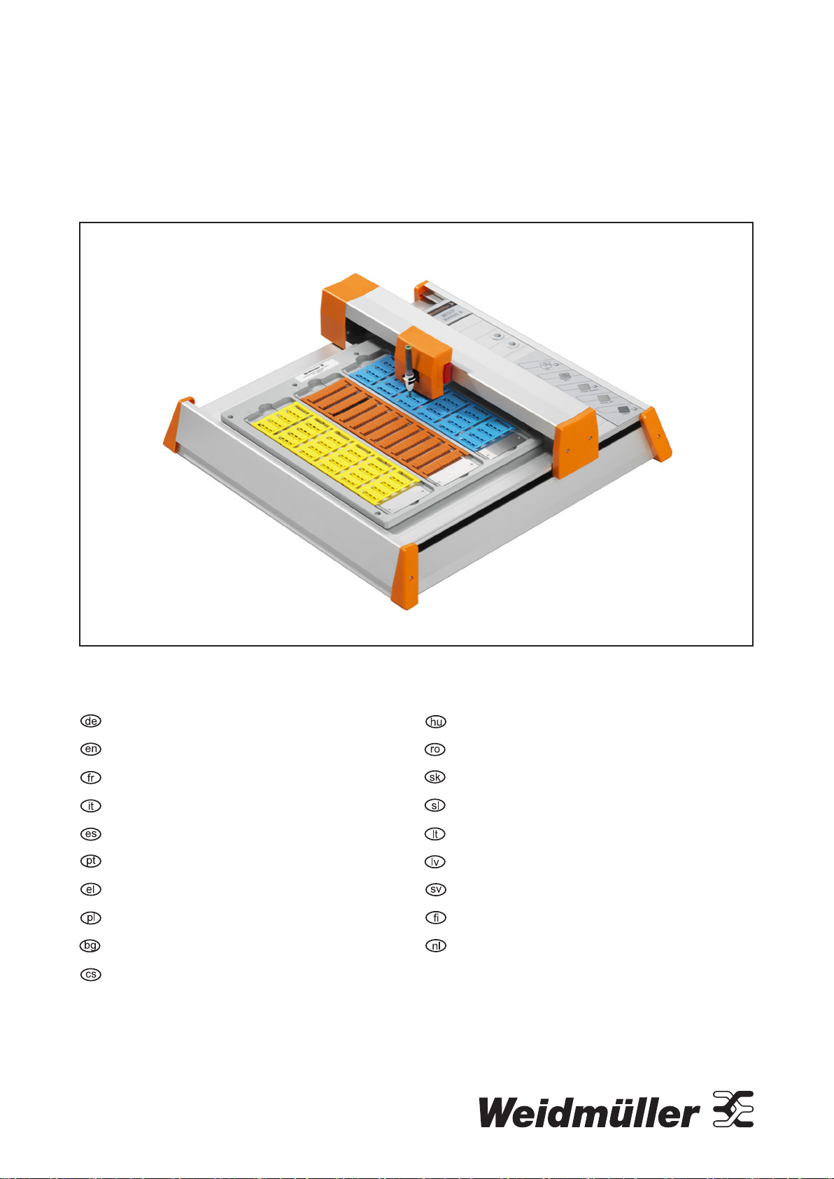
Plotter MCP Basic 2
Bedienungsanleitung ............................................. 3
Operating instructions ......................................... 19
Mode d’emploi ...................................................... 35
Istruzioni d‘uso ..................................................... 51
Manual de instrucciones .....................................67
Instruções de funcionamento ..............................83
Οδηγίες χειρισμού .................................................99
Instrukcja obsługi ...............................................115
Инструкции за работа .......................................131
Návod kobsluze ..................................................147
Üzemeltetési útmutató ......................................163
Instrucțiuni de utilizare ......................................179
Návod na použitie ...............................................195
Navodila za uporabo ...........................................211
Naudojimo instrukcija ........................................227
Lietošanas instrukcija ........................................243
Bruksanvisning ...................................................259
Käyttöohjeet .......................................................275
Bedieningsinstructies ........................................291
Page 2

1168680000/02/12.20162
Page 3

Inhalt
1 Über diese Dokumentation 4
2 Sicherheit 5
2.1 Bestimmungsgemäßer Gebrauch 5
2.2 Beschriftungselemente 5
2.3 Elektrischer Anschluss 5
2.4 Bedienpersonal 5
2.5 Konformität 5
2.6 Entsorgung/Recycling 5
3 Transport und Aufstellort 6
3.1 Plotter aufstellen 6
4 Gerätebeschreibung 7
4.1 Machen Sie sich mit dem Plotter vertraut 9
5 Inbetriebnahme 11
5.1 Software installieren 11
5.2 Plotter anschließen 11
5.3 Plotterstift einsetzen/wechseln 11
5.4 Plotter bestücken 12
Plotter MCP Basic 2
Bedienungsanleitung
6 Bedienung 13
6.1 Schreibvorgang unterbrechen/
Stop-Modus 13
6.2 Schreibvorgang abbrechen/Datenspeicher leeren 13
6.3 Akustiksignal ausschalten/dekativieren 13
7 Reinigung und Instandhaltung 14
7.1 Plotter reinigen 14
8 Störungsbeseitigung 15
9 Technische Daten 16
10 Zubehör 17
Hersteller
Weidmüller Interface GmbH & Co. KG
Klingenbergstraße 16
D-32758 Detmold
T +49 5231 14-0
F +49 5231 14-292083
info@weidmueller.de
www.weidmueller.com
Dokument-Nr. 1168680000
Revision 02/12.2016
1168680000/02/12.2016
3
Page 4
1 Über diese Dokumentation
Die Sicherheitshinweise in dieser Dokumentation sind
nach Schwere der Gefahr unterschiedlich gestaltet.
WARNUNG
Lebensgefahr möglich!
Hinweise mit dem Signalwort „Warnung“
warnen Sie vor Situationen, die zu
tödlichen oder schweren Verletzungen
führen können, falls Sie die angegebenen
Hinweise nicht beachten.
ACHTUNG
Sachbeschädigung!
Hinweise mit dem Signalwort „Achtung“ warnen Sie
vor Gefahren, die eine Sachbeschädigung zur Folge
haben können.
Die situationsbezogenen Warnhinweise können
folgende Warnsymbole enthalten:
Symbol Bedeutung
Warnung vor gefährlicher elektrischer
Spannung
Dokumentation beachten
Texte neben diesem Pfeil sind Hinweise, die
nicht sicherheitsrelevant sind, aber wichtige
Informationen für das richtige und effektive
Arbeiten geben.
► Alle Handlungsanweisungen erkennen Sie an dem
schwarzen Dreieck vor dem Text.
– Aufzählungen sind mit Strichen markiert.
Bewahren Sie die Bedienungsanleitung so
auf, dass sie vom Bedienpersonal jederzeit
eingesehen werden kann.
Alle Dokumente können Sie auch von der
Weidmüller Website herunterladen.
1168680000/02/12.20164
Page 5

2 Sicherheit
2.1 Bestimmungsgemäßer Gebrauch
Der Plotter MCP Basic 2 ist für die Beschriftung von
Markierern oder Etiketten vorgesehen, die an industriellen Anlagen angebracht werden. Der Betrieb des
Plotters wird über die Software M-Print® PRO gesteuert.
Der Einsatzort ist im gewerblichen Bereich (Büroumgebung).
Das Gerät ist nur für die in der Bedienungsanleitung
beschriebene Anwendung mit den genannten Beschriftungselementen bestimmt.
Das Gerät darf nicht geöffnet werden. Reparaturen,
einschließlich der Austausch der Netzzuleitung, dürfen
nur von Elektrofachkräften durchgeführt werden.
Zum bestimmungsgemäßen Gebrauch
gehört auch das Beachten der Dokumentation.
2.2 Beschriftungselemente
Mit dem MCP Basic 2 können folgende Materialien
beschriftet werden:
– Markierer im MultiCard-Format
– Etiketten
2.6 Entsorgung/Recycling
Stellen Sie sicher, dass das Gerät nach Ende seines
Lebenszyklus entsprechend der lokal geltenden
Bestimmungen entsorgt wird.
Sie können das Gerät zur fachgerechten Entsorgung
an Weidmüller zurückgeben. Senden Sie es einfach
per Parcelservice (im Karton) an das Weidmüller
Tochterunternehmen, welches Sie betreut, wir übernehmen dann alle anfallenden Recycling- und Entsorgungsmaßnahmen.
2.3 Elektrischer Anschluss
Das Gerät kann in den Spannungsbereichen
100 – 240VAC / 50 – 60Hz betrieben werden. Die
elektrischen Anschlussbedingungen müssen mit den
Angaben auf dem Typenschild übereinstimmen.
2.4 Bedienpersonal
Diese Bedienungsanleitung wendet sich an ausgebildetes Fachpersonal, das sich mit den geltenden Bestimmungen und Normen des Verwendungsbereichs
auskennt.
2.5 Konformität
Das Produkt entspricht folgenden europäischen Richtlinien:
– Niederspannungsrichtlinie 2014/35/EU
– EMV-Richtlinie 2014/30/EU
1168680000/02/12.2016
5
Page 6
3 Transport und Aufstellort
► Packen Sie die die Lieferung aus und prüfen Sie die
Vollständigkeit.
Folgende Komponenten gehören zum Lieferumfang:
– Plotter MCP Basic 2 mit Aufnahmeplatte
MCP AP BASIC und drei Verstellplatten MCPEP
– Netzstecker mit Anschlusskabel und montiertem
Euro-Adapter
– Adapter für US- und UK-Netzstecker
– Plotterstift 0,25
– USB-Kabel
– Software M-Print
Bewahren Sie die Umverpackung auf, damit
das Gerät im Servicefall sicher transportiert
werden kann.
®
PRO auf DVD
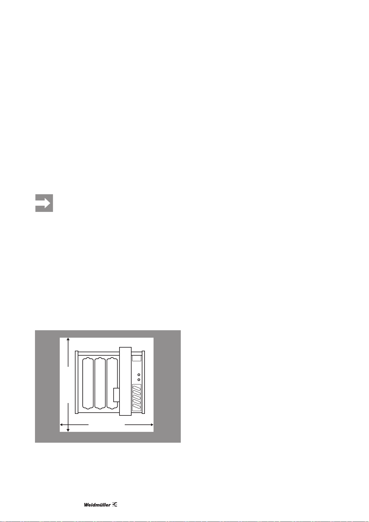
3.1 Plotter aufstellen
Der Aufstellort muss folgende Kriterien erfüllen:
– Trockener, möglichst staubfreier Raum
– Umgebungsbedingungen s.Kapitel9.
– Keine direkte Sonneneinstrahlung
– Netzsteckdose in der Nähe
– Stabiler, ebener Untergrund
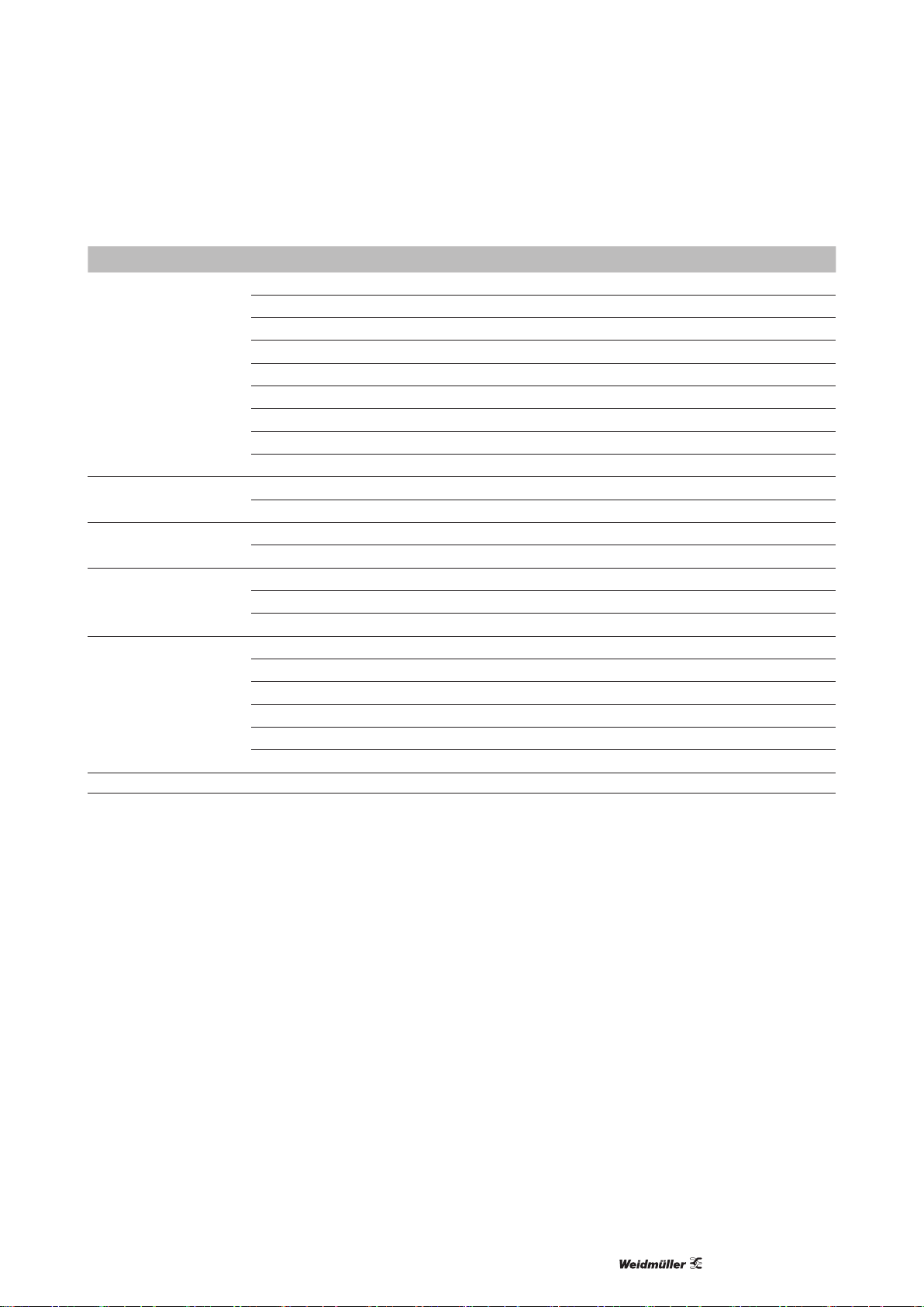
– Ausreichend Freiäche, sodass die Anschlüsse
jederzeit zugänglich sind und der bewegliche
Schreibarm im Betrieb nicht behindert wird.
≥ 600 mm
≥ 600 mm
Bild 3.1 Platzbedarf Plotter MCP Basic 2
1168680000/02/12.20166
Page 7

1
3
5 6 87
9
2
4
1112 10
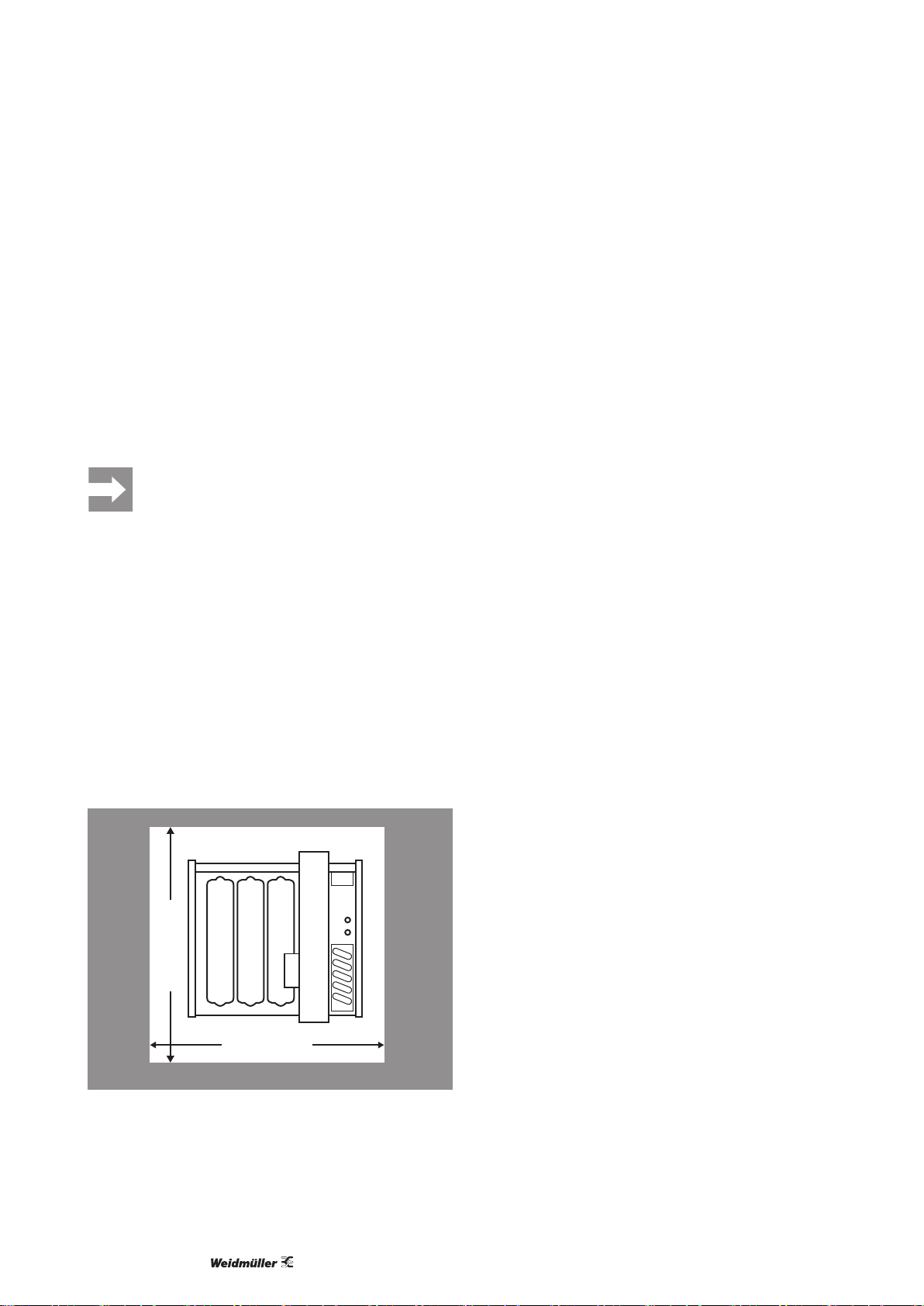
4 Gerätebeschreibung
Bild 4.1 Produktübersicht
1 Plottergrundplatte
2 Aufnahmeplatte
3 Verstellplatte
4 Positionierhilfe für Aufnahmeplatte
5 Stifthalter
6 Absenkeinheit
7 Schreibarm
8 Bedienfeld
9 Aufbewahrung Stifte
10 Netzanschluss
11 Anschlussbuchse (Sub-D15)
12 USB-Anschluss
1168680000/02/12.2016
7
Page 8
Gerätebeschreibung
LED / Taste Funktion / Anzeige
ON
OFF
Clear buffer
beep off
1
2
3
4
5
1 Taste ON Plotter einschalten
2 LED ON Grün: Plotter betriebsbereit
3 Taste OFF Plotter ausschalten
4 Taste Clear buffer Datenspeicher löschen
5 LED Clear buffer Gelb: Daten im Datenspeicher des
Plotters vorhanden
6
7
6 Taste beep off Akustiksignal ausschalten
7 Taste STOP Plotter anhalten und wieder starten
Bild 4.2 Bedienfeld
STOP
8
8 LED STOP Rot: Plotter wurde gestoppt
1168680000/02/12.20168
Page 9

Gerätebeschreibung
4.1 Machen Sie sich mit dem Plotter vertraut
In diesem Abschnitt lernen Sie die Elemente des Plotters und ihre Funktionsweise
kennen. Das hilft Ihnen, die Handlungsanleitungen der folgenden Kapitel schneller
umzusetzen.
Funktionsweise
Die Daten für einen Beschriftungsauftrag werden
vom angeschlossenen PC in den Datenspeicher des
Plotters übertragen und gespeichert. Der Beschriftungsvorgang beginnt damit, dass der Schreibarm
zur Startposition fährt und die Beschriftung startet.
Wenn der Beschriftungsvorgang beendet ist, fährt der
Schreibarm zurück in die Ausgangsposition und ein
Akustiksignal ertönt (s.„Akustiksignal“).
Autojustierung
Bei jedem Einschalten und beim Fortsetzen eines
Schreibvorgangs führt der Plotter eine Autojustierung
durch. Dabei fährt der Schreibarm ganz nach rechts
und der Stifthalter wird in die rechte obere Ecke
bewegt. Danach sollte der Schreibarm nicht mehr
berührt oder bewegt werden, da sonst die korrekte
Schreibposition nicht gewährleistet ist.
Akustiksignal
Sobald ein Schreibvorgang beendet ist, ertönt alle 20
Sekunden ein Akustiksignal. Dadurch wird darauf aufmerksam gemacht, dass sich der Plotterstift noch im
Stifthalter bendet und austrocknen kann.
Das Signal kann mit der Taste „beep off“ ausgeschaltet werden oder dauerhaft deaktiviert werden.
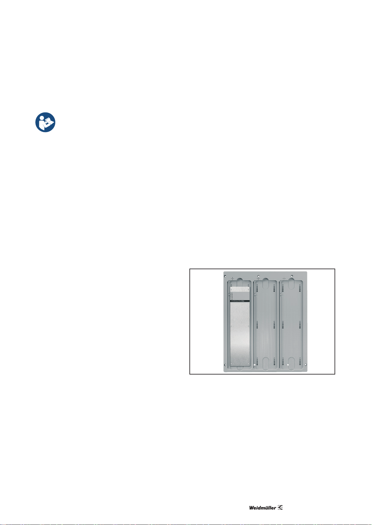
Aufnahmeplatte für Beschriftungselemente
Die Beschriftungselemente müssen in eine Aufnahmeplatte eingelegt werden, damit sie auf dem Plotter
exakt positioniert werden. Am oberen und unteren
Rand der Schreibäche sind jeweils zwei Fangstifte in
der Grundplatte des Plotters befestigt. Diese Fangstifte
dienen als Positionierhilfe für die Aufnahmeplatten.
Mit dem MCP Basic 2 können Sie verschiedene
Aufnahmeplatten verwenden:
– Aufnahmeplatte für MultiCard (im Lieferumfang)
– Aufnahmeplatte für Markierer SlimFix (SF4 bis SF6)
– Aufnahmeplatte für Etikettierbogen DIN A 4
Bedienelemente und Anzeigen
Alle Bedienelemente und LED-Anzeigen sind auf dem
Bedienfeld untergebracht. Die quadratischen Bedientasten reagieren auf leichten Fingerdruck.
Schreibarm
Der Schreibarm mit dem Stifthalter bewegt sich im Be-
trieb selbstständig über die Schreibäche. Deshalb ist
es wichtig, dass er nicht durch Gegenstände auf der
Schreibäche oder neben dem Plotter behindert wird.
Plotterstifte
Plotterstifte, die gerade nicht gebraucht werden, können
in den seitlich angebrachten Aufbewahrungsöffnungen gesteckt werden.
Bild 4.3 Aufnahmeplatte mit Verstellplatte
1168680000/02/12.2016
9
Page 10

Gerätebeschreibung
Stop-Modus/Taste STOP
Bei Bedarf können Sie den Plotter in den Stop-Modus
bringen (z.B. um einen Schreibvorgang zu unterbrechen). Mit der Taste STOP wechseln Sie zwischen
Betriebs- und Stop-Modus. Im Stop-Modus leuchtet
die LED STOP rot.
Datenspeicher
Wenn Druckdaten im Plotter gespeichert sind, leuchtet
die LED Clear buffer gelb. Um einen Druckauftrag abzubrechen, müssen Sie den Datenspeicher leeren
(s.Kapitel6.2).
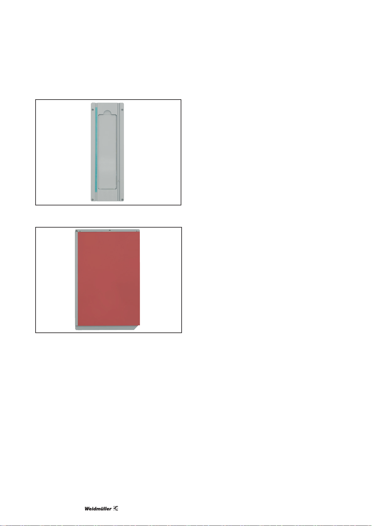
Bild 4.4 Aufnahmeplatte für Markierer SlimFix
Bild 4.5 Aufnahmeplatte für Etikettierbogen DIN A4
Verstellplatten
Da die verschiedenen Beschriftungselemente keine
einheitliche Materialstärke haben, muss ihre unterschiedliche Höhe mit Verstellplatten ausgeglichen
werden. So ist gewährleistet, dass sich die zu beschrif-
tende Oberäche immer auf gleicher Höhe bendet
und optimal vom Plotterstift getroffen wird. Welche
Position die Verstellplatte haben soll, wird für jeden
Beschriftungsauftrag durch die Software vorgegeben
(s.Kapitel5.4).
1168680000/02/12.201610
Page 11

5 Inbetriebnahme
5.1 Software installieren
Die Betriebssoftware M-Print® PRO nden Sie auf der
mitgelieferten DVD.
► Installieren Sie die Software auf dem PC.
► Folgen Sie den Anweisungen der Installationsroutine.
Die Anleitung zur Software nden Sie ebenfalls auf der mitgelieferten DVD.
5.2 Plotter anschließen
WARNUNG
Lebensgefahr möglich!
Das Netzteil hat eine variable
Eingangswechselspannung von
100 – 240VAC/50 – 60Hz.
► Stellen Sie sicher, dass der vorgese-
hene Netzanschluss geeignet ist und
in ordnungsgemäßem Zustand ist .
► Falls erforderlich, wechseln Sie den Adapter am
Netzstecker (für US oder UK).
► Schließen Sie das Netzanschlusskabel an den
Plotter an (Bild 4.1, Pos.10).
► Stecken Sie den Netzstecker in die Steck dose.
► Schließen Sie das USB-Kabel am Plotter an
(Bild4.1, Pos.12) und verbinden Sie es mit dem PC.
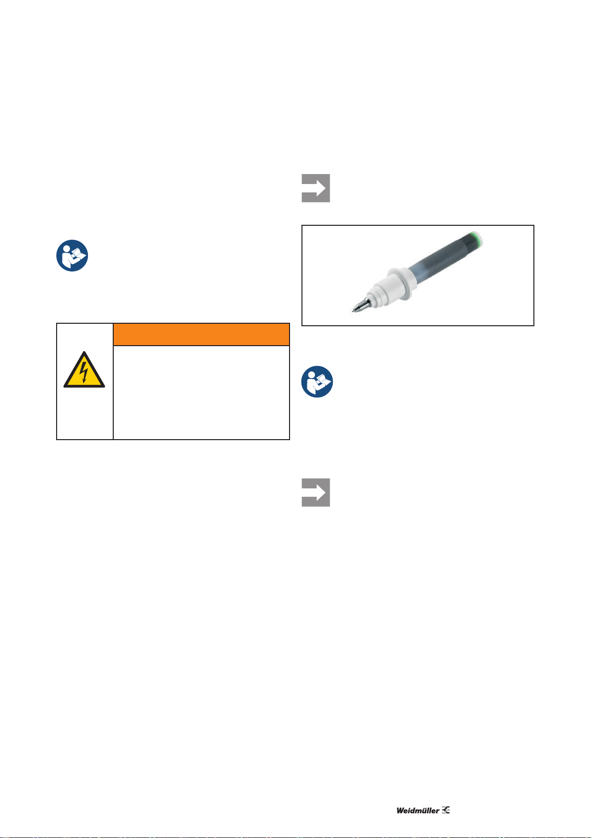
5.3 Plotterstift einsetzen/wechseln
Verwenden Sie nur Plotterstifte, die als
Zubehör genannt sind (s. Kapitel10).
Bild 5.1 Plotterstift
Beachten Sie die Anleitung, die dem Plotterstift beiliegt.
► Schreiben Sie den Plotterstift manuell an, bevor Sie
ihn einsetzen. Verwenden Sie dafür ausschließlich
eine Kunststoffoberäche.
► Stecken Sie den Plotterstift in den Stifthalter an der
Absenkeinheit des Schreibarms.
Falls der Plotter schon eingeschaltet war,
schalten Sie ihn aus- und wieder ein. Nur so
ist sichergestellt, dass die Autojustierung
wirksam ist.
1168680000/02/12.2016
11
Page 12
Inbetriebnahme
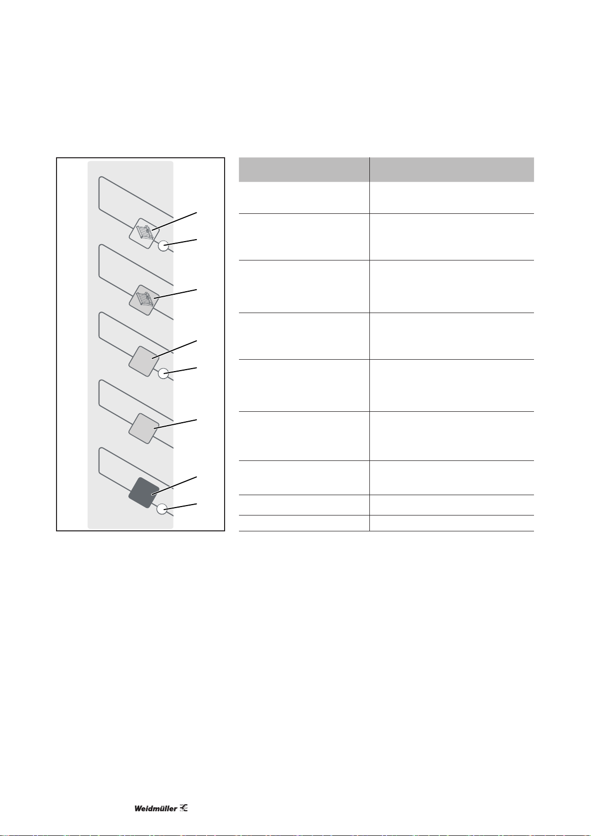
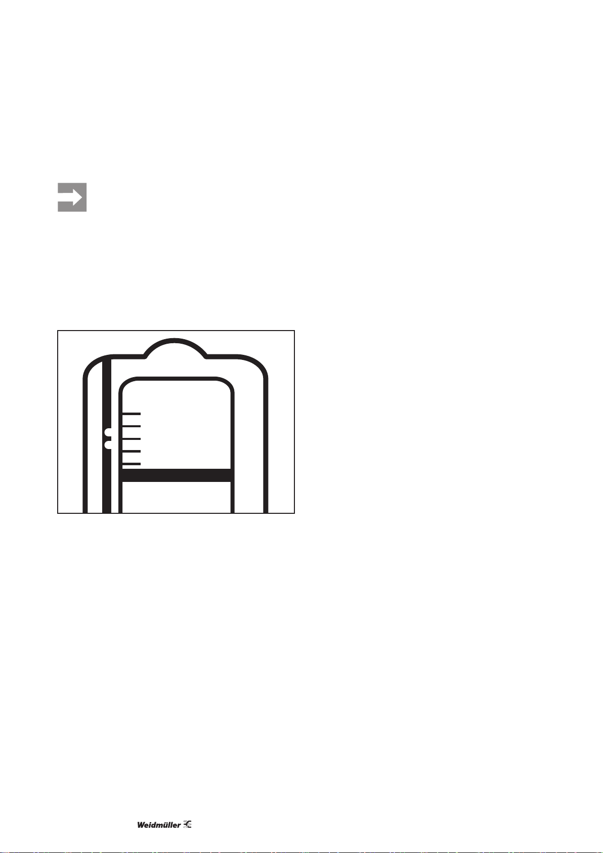
5.4 Plotter bestücken
Wir empfehlen, die Aufnahmeplatten außerhalb des Plotters vorzubereiten und sie im
Plotter zu platzieren bevor der Plotter eingeschaltet wird. So können Sie sicher sein,
dass die Autojustierung wirksam ist, selbst
wenn der Schreibarm beim Bestücken
bewegt wird.
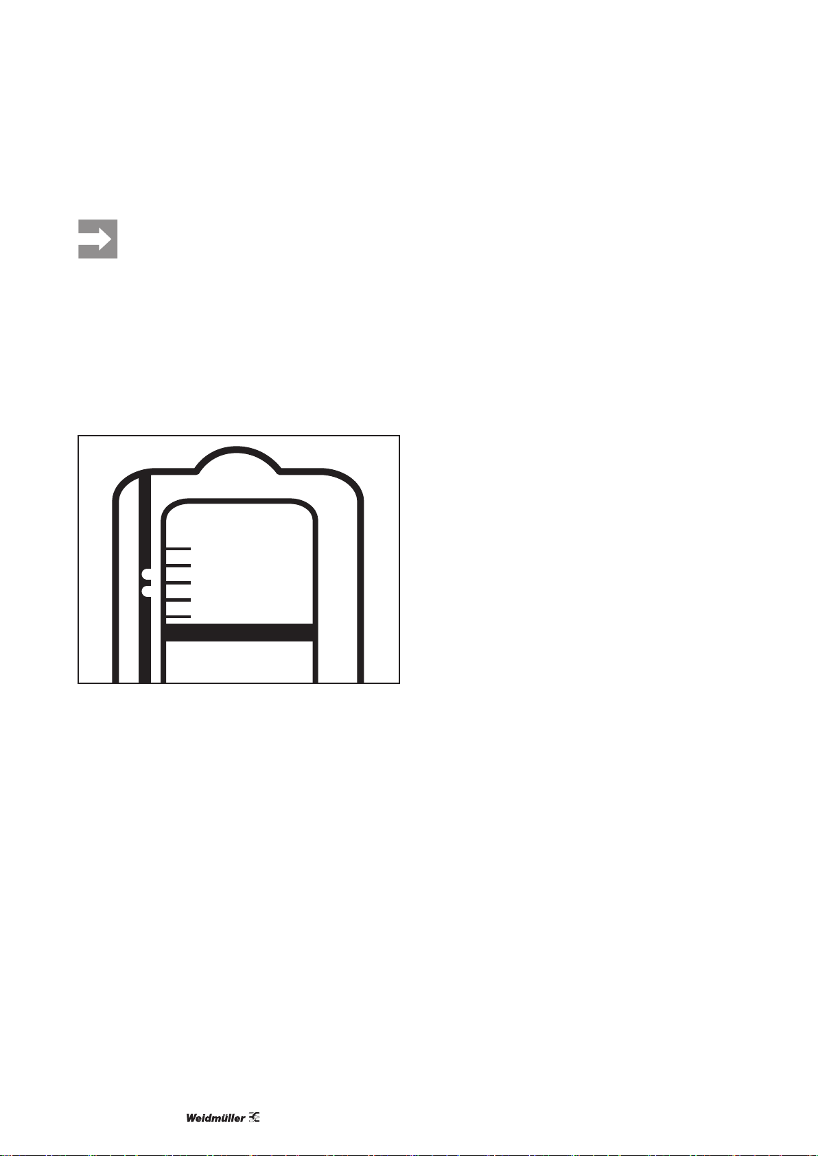
► Legen Sie die Verstellplatte so in die Aufnahmeplatte
ein wie von der Software vorgegeben (Vorgabe
Position 1 bis 5, Position 6 bedeutet ohne Verstell-
platte).
1
2
3
4
5
6=without this inlay
Bild 5.2 Verstellplatte positionieren (hier: Position 3)
► Legen Sie die Beschriftungselemente auf die
Verstellplatte.
► Platzieren Sie die fertig bestückte Aufnahmeplatte
linksbündig auf der Grundplatte des Plotters und so,
dass sie von den Fangstiften aufgenommen wird.
1168680000/02/12.201612
Page 13

6 Bedienung
Der übliche Ablauf beim Beschriften ist dieser:
► Software starten
► Druckauftrag einrichten
► Plotter mit Beschriftungsmaterial bestücken
► Plotterstift anschreiben und einstecken
► Plotter einschalten
► Druckauftrag starten.
Vor dem Einschalten des Plotters: Stellen
Sie sicher, dass sich auf der Schreibäche
und neben dem Plotter keine Gegenstände
benden, die die Bewegung des Schreib
armes behindern.
6.1 Schreibvorgang unterbrechen/
Stop-Modus
Sie können einen Schreibvorgang jederzeit unterbrechen und später fortsetzen.
► Drücken Sie die Taste STOP, um einen laufenden
Schreibvorgang anzuhalten und wieder zu starten.
Der Plotter fährt in die rechte obere Ecke der Schreibäche. Die LED STOP leuchtet rot.
► Drücken Sie die Taste STOP, um einen unterbrochenen
Schreibvorgang fortzusetzen.
Der Plotter nimmt den Betrieb wieder auf und setzt
den Schreibvorgang an der Stelle fort, wo er unterbrochen
wurde.
6.3 Akustiksignal ausschalten/dekativieren
► Um das Akustiksignal auszuschalten, drücken Sie
die Taste beep off.
Wenn Sie das Signal dauerhaft deaktivieren wollen,
gehen Sie wie folgt vor:
► Schalten Sie den Plotter ggf. aus.
► Halten Sie gleichzeitig die Tasten Clear buffer und
beep off gedrückt.
► Drücken Sie die Taste ON, um den Plotter einzu-
schalten.
Wenn Sie das Signal wieder aktivieren wollen, führen
Sie diesen Ablauf erneut durch.
6.2 Schreibvorgang abbrechen/Datenspeicher leeren
Wenn Sie einen Schreibvorgang abbrechen wollen,
müssen Sie die aktuellen Druckdaten aus dem Speicher
löschen.
► Wechseln Sie in den Stop-Modus (Taste STOP).
► Drücken Sie die Taste Clear buffer.
Die Daten werden gelöscht, die LED Clear buffer geht
aus.
► Drücken Sie die Taste STOP, um wieder in den
Betriebsmodus zu wechseln.
1168680000/02/12.2016
13
Page 14

7 Reinigung und Instandhaltung
7.1 Plotter reinigen
ACHTUNG
Plotter kann beschädigt werden!
Die Oberäche des Plotters kann durch Lösemittel
und aggressive Reiniger beschädigt werden.
► Bei Bedarf verwenden Sie nur die als Zubehör
empfohlenen Reiniger.
► Ölen Sie niemals mechanische Teile Ihres Plotters!
► Schützen Sie den Plotter vor Staub und anderen
Verunreinigungen. Decken Sie ihn bei Nichtbenutzung ab.
Eine Abdeckung ist als Zubehör erhältlich
(s.Kapitel10).
► Reinigen Sie den Plotter nach der Benutzung mit
einem trockenen Tuch.
► Verwenden Sie bei Bedarf ein feuchtes Tuch und
ein mildes Reinigungsmittel.
1168680000/02/12.201614
Page 15

8 Störungsbeseitigung
Störungsbeseitigung
Störung
Gerät lässt sich nicht einschalten
Mögliche Ursache Empfohlene Maßnahme
Stromversorgung nicht angeschlossen Prüfen Sie, ob das Netzteil am Plotter und an
Keine Stromversorgung Lassen Sie die Steckdose von einem Elektro-
Netzteil defekt (grüne LED am Netzteil leuchtet
nicht, obwohl Stromversorgung gegeben ist)
Plotter reagiert nicht auf Daten, die vom PC
USB-Kabel nicht richtig angeschlossen Prüfen Sie, ob das USB-Kabel an Plotter und PC
gesendet werden.
Gerätetreiber ist nicht korrekt installiert Prüfen Sie, ob der Gerätetreiber bereits auf dem
Der Plotter geht in Betrieb, aber es erfolgt
Plotterstift eingetrocknet Falls nötig, entnehmen Sie den Plotterstift aus
keine Beschriftung.
Plotterstift leer Entnehmen Sie den Plotterstift aus dem
Schlechtes Schriftbild, Linienstärke un-
Spitze des Plotterstifts verunreinigt Entnehmen Sie den Plotterstift aus dem Stift-
gleichmäßig, Aussetzer in der Beschriftung
1) Verwenden Sie nur die Reiniger, die als Zubehör genannt sind (s. Kapitel10).
Tab. 8.1 Störungsbeseitigung MCP Basic 2
der Stromversorgung angeschlossen ist.
fachkraft prüfen.
Wechseln Sie ggf. zu einer anderen Steckdose.
Tauschen Sie das Netzteil aus.
richtig angeschlossen ist.
Falls nötig, tauschen Sie das Datenkabel aus.
PC installiert wurde.
Falls nötig, installieren Sie den Gerätetreiber.
dem Stifthalter und säubern Sie die Spitze vorsichtig mit einem Stofftuch, das mit Reinigungs-
1)
üssigkeit
getränkt ist.
Stifthalter und füllen Sie ihn auf oder tauschen
Sie ihn aus.
halter und säubern Sie die Spitze vorsichtig mit
einem Stofftuch, das mit Reinigungsüssigkeit
getränkt ist.
1)
Sollte eine Störung durch die beschriebenen Maßnahmen nicht beseitigt werden,
wenden Sie sich bitte an den Weidmüller
Service.
1168680000/02/12.2016
15
Page 16

9 Technische Daten
Technische Daten MCP Basic 2
Typ Flachbettplotter
Maximale Plotäche 273mm x 305mm
Plotgeschwindigkeit max. 40mm/s
Plotterstifte Spezial-Plotterstifte mit HP-Aufnahme
Datenschnittstelle USB 2.0
Befehlssprache basierend auf HP-GL 7475A
Datenspeicher im Gerät 16 MB
Antrieb Zweiphasen-Schrittmotor
Adressierbare Auösung 0,01 mm
Wiederholgenauigkeit 0,05 mm
Wiederholgenauigkeit bei Stiftwechsel 0,05 mm bei optimalem Stift
Spannungsversorgung Über externes Steckernetzteil mit auswechselbarem Adapter
Netzteil Eingangspannung 100 – 240V AC / 50 – 60Hz
Eingangsstrom 0,7 A max.
Ausgangsspannung 24 V DC
Ausgangsstrom 1,25 A max.
Umgebungsbedingungen Betrieb 10 °C ... 35 °C
35 % ... 75 % rel. Luftfeuchtigkeit
Lagerung -10 °C ... 50 °C
10 % ... 90 % rel. Luftfeuchtigkeit
Sicherheitszertikate EN 60950-1:2006 + A11:2009, A1:2010, A12:2011, AC:2011, A2:2013
Störsicherheit
Maße 470 mm x 480 mm x 155 mm
Gewicht 6,3 kg
Tab. 9.1 Technische Daten MCP Basic 2
EN 61000-4-2, 4-4, 4-5, 4-6, 4-11
1168680000/02/12.201616
Page 17
10 Zubehör
Artikel Typ Beschreibung Best.-Nr.
Plotterstifte Plotterpen 0,18 Mehrwegstift 1768570000
Plotterpen 0,25 Mehrwegstift 1768540000
Plotterpen 0,25 P-Ink
1)
Plotterpen 0,35 Mehrwegstift 1768550000
Plotterpen 0,35 P-Ink
1)
Plotterpen 0,50 Mehrwegstift 1768560000
Plotterpen 0,50 P-Ink
1)
Plotterpen 0,70 Mehrwegstift 1011440000
Plotterpen 0,70 P-Ink
Stifte STI Stift SW
1)
1)
Adapter Alu STI-S Adapter für STI-Stift 1762440000
Tinte P-Ink 2.0
1)
Tinte 2000 25 ml 1772120000
Aufnahmeplatten MCP AP BASIC Für MultiCard-Matten 1139880000
MCP AP SF4-6 Für SlimFix Größe 4 bis 6 1924310000
MCP AP LABELS Für Etiketten 1924370000
Sonstiges MCP Klebestreifen 1924320000
P-CLEANER Reiniger, 30 ml 1924330000
Reiniger 2000 Reiniger, 25 ml 1772130000
MCP COVER Abdeckhaube 1924350000
MCP EP Verstellplatte 1935130000
MCP EP SFC 3 Inlay 1058090000
1) Nicht geeignet zum Beschriften von CLIT-Hülsen
Einwegstift 8 ml 1920640000
Einwegstift 8 ml 1920650000
Einwegstift 8 ml 1005710000
Einwegstift 8 ml 1011450000
0508401694
30 ml 1924340000
Tab. 10.1 Zubehör MCP Basic 2
1168680000/02/12.2016
17
Page 18

1168680000/02/12.201618
Page 19

Contents
1 About this documentation 20
2 Safety 21
2.1 Intended use 21
2.2 Labelling elements 21
2.3 Electrical connection 21
2.4 Operating personnel 21
2.5 Conformity 21
2.6 Disposal/recycling 21
3 Transport and installation site 22
3.1 Setting up the plotter 22
4 Device description 23
4.1 Getting to know the plotter 25
5 Commissioning 27
5.1 Installing the software 27
5.2 Connecting the plotter 27
5.3 Inserting/replacing the plotter pen 27
5.4 Loading the plotter 28
MCP Basic 2 plotter
Operating instructions
6 Operation 29
6.1 Pausing the write process / stop mode 29
6.2 Cancelling the write process / emptying the data memory 29
6.3 Switching off/deactivating the acoustic signal 29
7 Cleaning and maintenance 30
7.1 Cleaning the plotter 30
8 Troubleshooting 31
9 Technical data 32
10 Accessories 33
Manufacturer
Weidmüller Interface GmbH & Co. KG
Klingenbergstraße 16
D-32758 Detmold
T +49 5231 14-0
F +49 5231 14-292083
info@weidmueller.com
www.weidmueller.com
Document no. 1168680000
Revision 02/12.2016
1168680000/02/12.2016
19
Page 20

1 About this documentation
The safety notes in this documentation are designed
according to the severity of the danger.
WARNING
Possible danger to life!
Notes with the signal word “Warning”
warn you of situations which may result
in serious injury or death if you do not
follow the instructions given in this
manual.
ATTENTION
Material damage!
Notes with the signal word “Attention” warn you of
hazards which may result in material damage.
The situation-dependent warnings may contain the
following warning symbols:
Symbol Meaning
Warning against hazardous electrical
voltage
Observe the documentation
Text next to this arrow are notes which are
not relevant to safety, but provide important
information about proper and effective work
procedures.
► All instructions can be identied by the black triangle
next to the text.
– Lists are marked with a tick.
Please keep the operating instructions
where they can be viewed by the operating
personnel at all times.
All documents can also be downloaded
from the Weidmüller website.
1168680000/02/12.201620
Page 21

2 Safety
2.1 Intended use
The MCP Basic 2 plotter is designed for the labelling
of markers or labels tted to industrial systems.
The operation of the plotter is controlled by the
M-Print® PRO software. It is designed for commercial
environments (ofces).
The device is only intended for the application
described in the operating instructions with the
labelling elements described.
The device must not be opened. Repairs, including
replacing the power pack, must be carried out by a
qualied electrician.
Observance of the documentation is also
part of the intended use.
2.2 Labelling elements
The following materials can be labelled with the
MCP Basic 2:
– Markers in MultiCard format
– Labels
2.6 Disposal/recycling
At the end of its service life, make sure the device is
disposed of in accordance with the local regulations.
You can also return the device to Weidmüller for proper
disposal. Simply send it by parcel service (in a box)
to the Weidmüller subsidiary that supports you. We
will then take care of all of the recycling and disposal
activities.
2.3 Electrical connection
The device can be operated in the 100–240 V AC /
50–60 Hz voltage ranges. The electrical connection
conditions must correspond to the information on the
type plate.
2.4 Operating personnel
These operating instructions have been written for
trained and qualied personnel who are familiar with
the valid regulations and standards applicable to the
eld of application.
2.5 Conformity
The product complies with the following European
directives:
– Low Voltage Directive 2014/35/EU
– EMC Directive 2014/30/EU
1168680000/02/12.2016
21
Page 22
3 Transport and installation site
► Unpack the delivery and check everything is there.
The delivery includes the following components:
– MCP Basic 2 plotter with MCP AP BASIC mounting
plate and three MCPEP adjuster plates
– Mains plug with connection cable and a tted Euro
adapter
– Adapter for US and UK mains plug
– 0.25 plotter pen
– USB cable
– M-Print
3.1 Setting up the plotter
®
PRO software on DVD
Keep the packaging so you can transport
the device safely if it needs servicing.
The installation site must meet the following criteria:
– A dry room, as free of dust as possible
– For environmental conditions, see Chapter 9.
– No exposure to direct sunlight
– Power socket nearby
– Stable, at base
– Plenty of space so the connections are accessible
at all times and the movable writing arm is not
impeded when in use.
≥ 600 mm
≥ 600 mm
Fig. 3.1 Space required for MCP Basic 2 plotter
1168680000/02/12.201622
Page 23
1
3
5 6 87
9
2
4
1112 10
4 Device description
Fig. 4.1 Product overview
1 Plotter base plate
2 Mounting plate
3 Adjuster plate
4 Positioning aid for mounting plate
5 Pen holder
6 Lowering unit
7 Writing arm
8 Control panel
9 Pen storage
10 Mains connection
11 Connection socket (Sub-D 15)
12 USB connection
1168680000/02/12.2016
23
Page 24

Device description
LED/key Function/display
ON
OFF
Clear buffer
beep off
1
2
3
4
5
6
7
1 ON key Switch plotter on
2 ON LED Green: plotter operational
3 OFF key Switch plotter off
4 Clear buffer key Delete data memory
5 Clear buffer LED Yellow: data in plotter data memory
6 beep off key Switch off acoustic signal
7 STOP key Stop and restart plotter
STOP
Fig. 4.2 Control panel
8
8 STOP LED Red: plotter was stopped
1168680000/02/12.201624
Page 25
Device description
4.1 Getting to know the plotter
This section introduces you to the elements of
the plotter and how they work, so that you
can follow the instructions in subsequent
sections more easily.
How it works
The data for a labelling job is transferred from the
connected PC to the plotter’s data memory and saved.
The labelling process begins when the writing arm
moves to the start position and starts labelling. Once
the labelling process is complete, the writing arm
moves back to the start position and an acoustic
signal sounds (see “Acoustic signal”).
Auto-calibration
Every time it is switched on or a writing process is
continued, the plotter carries out the auto-calibration
process. As part of this process, the writing arm
moves all the way to the right and the pen holder is
moved to the top right-hand corner. At this point, do
not touch or move the writing arm, as otherwise the
correct writing position cannot be guaranteed.
Acoustic signal
As soon as the writing process is complete, an acoustic
signal sounds every 20 seconds. This indicates that
that the plotter pen is still in the pen holder and can
dry out.
The signal can be switched off or permanently
deactivated with the “beep off” key.
Mounting plate for labelling elements
The labelling elements must be inserted in a mounting
plate so that they can be positioned in precise locations
on the plotter. At the top and bottom edges of the
writing surface, there are two holding pins xed to
the base plate of the plotter. These holding pins are a
positioning guide for the mounting plates.
You can use various mounting plates with the
MCP Basic 2:
– Mounting plate for MultiCard (supplied)
– Mounting plate for SlimFix markers (SF4 to SF6)
– Mounting plate for DIN A4 labelling sheets
Controls and displays
All the controls and LED displays are on the control
panel. The square control keys react to a gentle touch
with the nger.
Writing arm
When in operation, the writing arm with the pen holder
moves automatically across the writing surface. It is
therefore important that it is not hampered by objects
on the writing surface or near the plotter.
Plotter pens
Plotter pens that are not in use can be inserted in the
storage openings on the side.
Fig. 4.3 Mounting plate with adjuster plate
1168680000/02/12.2016
25
Page 26
Device description
Data memory
If print data is stored in the plotter, the Clear buffer
LED lights up yellow. To cancel a print job, you need to
wipe the data memory (see Chapter 6.2).
Fig. 4.4 Mounting plate for SlimFix markers
Fig. 4.5 Mounting plate for DIN A4 labelling sheets
Adjuster plates
As the various labelling elements do not have a consistent thickness, the different heights need to be balanced out using the adjuster plates. This guarantees
that the surface to be labelled is always at the same
height and can make optimum contact with the plotter pen. The position the adjuster plate should have
is dened by the software for each labelling job (see
Chapter 5.4).
Stop mode / STOP key
If necessary, you can put the plotter into stop mode
(e.g.to stop a write process). Use the STOP key to
switch between operating and stop mode. In stop
mode, the STOP LED lights up red.
1168680000/02/12.201626
Page 27
5 Commissioning
5.1 Installing the software
The M-Print® PRO operating software can be found on
the DVD provided.
► Install the software on the PC.
► Follow the instructions in the installation routine.
The software instructions can also be found
on the DVD provided.
5.2 Connecting the plotter
WARNING
Possible danger to life!
The power pack has a variable AC input
voltage of 100–240 V AC / 50–60 Hz.
► Make sure that the mains connection
provided is suitable and in good
working condition.
► If necessary, replace the adapter on the mains plug
(for US or UK).
► Connect the mains connection cable to the plotter
(Fig. 4.1, number 10).
► Plug the mains connector into the socket.
► Connect the USB cable to the plotter (Fig. 4.1,
number 12) and connect it to the PC.
5.3 Inserting/replacing the plotter pen
Only use the plotter pens specied as
accessories (see Chapter 10).
Fig. 5.1 Plotter pen
Follow the instructions provided with the
plotter pen.
► Test the plotter pen manually before you use it. Only
use a plastic surface for this purpose.
► Insert the plotter pen in the pen holder on the
lowering unit of the writing arm.
If the plotter was already switched on,
switch it off and back on again. This is the
only way to guarantee that the auto-calibration
process is effective.
1168680000/02/12.2016
27
Page 28
Commissioning
5.4 Loading the plotter
We recommend preparing the mounting
plates off the plotter and placing them in
the plotter before the plotter is switched
on. This allows you to be certain that the
auto-calibration process is effective, even
when the writing arm is moved during the
loading process.
► Fit the adjuster plate into the mounting plate as
shown in the software (specication position 1 to
5, position 6 means no adjuster plate).
1
2
3
4
5
6=without this inlay
Fig. 5.2 Positioning the adjuster plate (here: position 3)
► Place the labelling elements on the adjuster plate.
► Place the fully loaded mounting plate ush to the
left on the base plate of the plotter so it is held by
the holding pins.
1168680000/02/12.201628
Page 29

6 Operation
For labelling, the normal process is:
► Start the software
► Set up print job
► Load plotter with labelling material
► Test the plotter pen and insert it
► Switch plotter on
► Start the print job.
Before switching on the plotter, make sure
there are no objects on the writing surface
and next to the plotter which could impede
the movement of the writing arm.
6.1 Pausing the write process / stop mode
You can pause a write process at any time and continue
it later.
► Press the STOP key to pause and restart an ongoing
write process.
The plotter moves to the right upper corner of the writing
surface. The STOP LED lights up red.
► Press the STOP key to continue a paused write
process.
The plotter resumes and continues the write process
from the point at which it was paused.
6.3 Switching off/deactivating the acoustic signal
► To switch off the acoustic signal, press the beep off
key.
If you wish to permanently deactivate the signal,
proceed as follows:
► Switch the plotter off, as necessary.
► Hold down the Clear buffer and beep off keys at the
same time.
► Press the ON key to switch the plotter on.
Repeat this process to reactivate the signal.
6.2 Cancelling the write process / emptying the data memory
If you wish to cancel a write process, you need to
delete the current print data from the memory.
► Switch to stop mode (STOP key).
► Press the Clear buffer key.
The data is deleted and the Clear buffer LED goes out.
► Press the STOP key to switch back to operating
mode.
1168680000/02/12.2016
29
Page 30

7 Cleaning and maintenance
7.1 Cleaning the plotter
ATTENTION
Risk of damage to plotter!
Solvents and abrasive detergents can damage the
surface of the plotter.
► If possible, use only the detergents recommended
as accessories.
► Never oil the mechanical parts of your plotter!
► Protect the plotter from dust and other contamination.
Cover the plotter when not in use.
A cover is available as an accessory (see Chapter 10).
► Clean the plotter with a dry cloth after use.
► If necessary, use a damp cloth and a mild detergent.
1168680000/02/12.201630
Page 31

8 Troubleshooting
Troubleshooting
Fault
Device cannot be switched on
Possible cause Recommended action
Power supply not connected Check that the power pack is connected to the
No power supply Have the socket checked by an electrician.
Power pack faulty (green LED on power pack
does not light up even though the power supply
is connected)
Plotter does not react to data sent by the
USB cable not connected properly Check that the USB cable is properly connected
PC.
Device driver not correctly installed Check whether the device driver is installed on
The plotter starts up, but labelling is not
Plotter pen dried out If necessary, remove the plotter pen from the
created.
Plotter pen empty Remove the plotter pen from the pen holder and
Poor printing, uneven line thickness,
Contamination on plotter tip Remove the plotter pen from the pen holder and
missing parts of labels
1) Only use the detergents specied as accessories (see Chapter 10).
Tab. 8.1 MCP Basic 2 troubleshooting
plotter and to the power supply.
If necessary, switch to another socket.
Replace the mains power pack.
to the plotter and the PC.
If necessary, replace the data cable.
the PC.
If necessary, install the device driver.
pen holder and clean the tip carefully with a
1)
cloth dipped in cleaning uid
.
rell or replace it.
clean the tip carefully with a cloth dipped in
1)
cleaning uid
.
If there is a fault that cannot be remedied
using the measures described above,
please contact the Weidmüller Service
Department.
1168680000/02/12.2016
31
Page 32

9 Technical data
Technical data MCP Basic 2
Type Flatbed plotter
Maximum plotting area 273mm x 305mm
Plotting speed max. 40 mm/s
Plotter pens Special plotter pens with HP holder
Data interface USB 2.0
Command language Based on HP GL 7475A
Device data memory 16 MB
Drive Two-phase stepper motor
Addressable resolution 0.01 mm
Repeat accuracy 0.05 mm
Repeat accuracy on pen change 0.05 mm with optimal pen
Power supply Via external power pack with replaceable adapter
Power pack Input voltage 100–240V AC / 50–60Hz
Input current max. 0.7 A
Output voltage 24 V DC
Output current max. 1.25 A
Environmental conditions Operation 10°C ... 35°C
35% ... 75% relative humidity
Storage -10°C ... 50°C
10% ... 90% relative humidity
Safety certicates EN 60950-1:2006 + A11:2009, A1:2010, A12:2011, AC:2011, A2:2013
Interference resistance
Dimensions 470 mm x 480 mm x 155 mm
Weight 6.3 kg
Tab. 9.1 Technical data MCP Basic 2
EN 61000-4-2, 4-4, 4-5, 4-6, 4-11
1168680000/02/12.201632
Page 33

10 Accessories
Part Type Description Order no.
Plotter pens Plotterpen 0.18 Reusable pen 1768570000
Plotterpen 0.25 Reusable pen 1768540000
Plotterpen 0.25 P-Ink
1)
Plotterpen 0.35 Reusable pen 1768550000
Plotterpen 0.35 P-Ink
1)
Plotterpen 0.50 Reusable pen 1768560000
Plotterpen 0.50 P-Ink
1)
Plotterpen 0.70 Reusable pen 1011440000
Plotterpen 0.70 P-Ink
Pens STI pen SW
1)
1)
Aluminium STI-S adapter Adapter for STI pen 1762440000
Ink P-Ink 2.0
1)
Ink 2000 25 ml 1772120000
Mounting plates MCP AP BASIC For MultiCard mats 1139880000
MCP AP SF4-6 For SlimFix size 4 to 6 1924310000
MCP AP LABELS For labels 1924370000
Miscellaneous MCP adhesive strips 1924320000
P-CLEANER Detergent, 30 ml 1924330000
Detergent 2000 Detergent, 25 ml 1772130000
MCP COVER Cover hood 1924350000
MCP EP Adjuster plate 1935130000
MCP EP SFC 3 Inlay 1058090000
1) Not suitable for labelling CLI T sleeves
8 ml disposable pen 1920640000
8 ml disposable pen 1920650000
8 ml disposable pen 1005710000
8 ml disposable pen 1011450000
0508401694
30 ml 1924340000
Tab. 10.1 Accessories MCP Basic 2
1168680000/02/12.2016
33
Page 34

1168680000/02/12.201634
Page 35

Sommaire
1 À propos de cette documentation 36
2 Sécurité 37
2.1 Plages d'utilisation 37
2.2 Éléments de repérage 37
2.3 Raccordement électrique 37
2.4 Opérateurs 37
2.5 Conformité 37
2.6 Recyclage / élimination 37
3 Transport et site d’installation 38
3.1 Mise en place du traceur 38
4 Description de l’appareil 39
4.1 À la découverte du traceur 41
5 Mise en service 43
5.1 Installation du logiciel 43
5.2 Connexion du traceur 43
5.3 Mise en place/remplacement du stylo pour traceur 43
5.4 Chargement du traceur 44
MCP Basic 2 traceur
Mode d'emploi
6 Fonctionnement 45
6.1 Pause du processus d’écriture /
mode Stop 45
6.2 Annulation du processus d’écriture /
suppression de la mémoire de données 45
6.3 Extinction / désactivation du signal sonore 45
7 Nettoyage et maintenance 46
7.1 Nettoyage du traceur 46
8 Dépannage 47
9 Données techniques 48
10 Accessoires 49
Fabricant
Weidmüller Interface GmbH & Co. KG
Klingenbergstraße 16
D-32758 Detmold
T +49 5231 14-0
F +49 5231 14-292083
mail@weidmuller.fr
www.weidmueller.com
N° de document 1168680000
Révision 02/12.2016
1168680000/02/12.2016
35
Page 36

1 À propos de cette documentation
Les consignes de sécurité gurant dans cette documentation sont rédigées selon leur degré de danger.
AVERTISSEMENT
Danger de mort éventuel!
Les remarques signalées par le terme
«Avertissement» préviennent de
situations susceptibles d'entraîner
des blessures graves, voire mortelles,
si vous ne suivez pas les instructions
fournies dans ce manuel.
ATTENTION
Dommage matériel!
Les remarques signalées par le terme «Attention»
vous préviennent de dangers risquant d’endommager
le matériel.
Selon les cas, les avertissements peuvent contenir les
symboles suivants:
Symbole Signifie
Avertissement au sujet d’une tension
électrique dangereuse
Consultez la documentation
Le texte gurant en regard de cette èche
constitue des remarques sans aucun rapport
avec la sécurité, mais qui vous donnent des
informations importantes sur des procédures
de travail sûres et efcaces.
► Toutes les instructions peuvent être identiées par
le triangle noir situé à côté du texte.
– Les éléments des listes sont précédés de tirets.
Veuillez conserver ce mode d’emploi à un
endroit où les opérateurs peuvent le consulter
à tout moment.
Tous les documents peuvent également
être téléchargés depuis le Site web de
Weidmüller.
1168680000/02/12.201636
Page 37

2 Sécurité
2.1 Plages d'utilisation
Le traceur MCP Basic 2 sert à imprimer des repérages
ou des étiquettes adaptés aux systèmes industriels.
Le fonctionnement du traceur est contrôlé à l’aide
du logicielMPrint® PRO. Il a été conçu pour les
environnements commerciaux (bureaux).
Cet appareil est uniquement destiné à l’usage précisé
dans le mode d’emploi, avec les éléments de repérage
décrits.
Cet appareil ne doit pas être ouvert. Seul un électricien
qualié est habilité à procéder à des réparations, y
compris le remplacement du bloc d’alimentation.
Le respect de la présente documentation
fait également partie des plages d'utilisation.
2.2 Éléments de repérage
Les matériaux suivants peuvent être imprimés avec le
traceur MCP Basic 2:
– Repérages au format MultiCard
– Étiquettes
Vous pouvez également retourner votre appareil à
Weidmüller an de vous assurer de son traitement
approprié. Il vous suft de l’expédier via un service
de livraison de colis (dans un carton) à la liale
Weidmüller qui vous sert de point de contact. Nous
nous chargerons alors du traitement des activités de
recyclage et d’élimination.
2.3 Raccordement électrique
Cet appareil admet une plage de tension variable de
100 à 240Vca pour 50–60Hz. Son raccordement
électrique doit remplir les conditions indiquées sur sa
plaque signalétique.
2.4 Opérateurs
Ce mode d’emploi a été rédigé à l’attention d’un
personnel formé et qualié, parfaitement familiarisé
avec les réglementations et les normes en vigueur
dans ce domaine d’application.
2.5 Conformité
Ce produit respecte les directives européennes
suivantes:
– Directive basse tension2014/35/CE
– Directive CEM2014/30/CE
2.6 Recyclage / élimination
À la n de sa durée de vie, veillez à éliminer cet
appareil conformément aux réglementations locales.
1168680000/02/12.2016
37
Page 38

3 Transport et site d’installation
► Déballez le colis reçu et vériez que rien ne
manque.
Le colis comprend les éléments suivants:
– MCP Basic 2 traceur avec MCP AP BASIC plaque de
maintien et trois plaques de réglage MCPEP
– Fiche secteur avec câble de raccordement et
adaptateur pour che Euro monté
– Adaptateur pour les ches secteur britanniques et
américaines
– Stylo pour traceur 0,25
– Câble USB
– Logiciel M-Print
Conservez l’emballage pour le transport de
l’appareil en toute sécurité s’il a besoin d'un
entretien.
®
PRO sur DVD
3.1 Mise en place du traceur
Le lieu d’installation doit répondre aux critères
suivants:
– Local sec et exempt de poussières, dans la mesure
du possible
– Pour les conditions environnementales, voir
chapitre9.
– Aucune exposition directe à la lumière du soleil
– Prise secteur à proximité
– Base stable et plane
– Espace sufsant permettant un accès permanent
aux raccordements ainsi que le déplacement sans
entrave du bras d’écriture en cours d’utilisation.
≥ 600 mm
≥ 600 mm
Fig. 3.1 Espace requis pour le traceur MCP Basic 2
1168680000/02/12.201638
Page 39

1
3
5 6 87
9
2
4
1112 10
4 Description de l’appareil
Fig. 4.1 Aperçu du produit
1 Plaque de base du traceur
2 Plaque de maintien
3 Plaque de réglage
4 Aide au positionnement de la plaque de maintien
5 Support de stylo
6 Unité d’abaissement
7 Bras d’écriture
8 Panneau de commande
9 Stockage du stylo
10 Raccordement au secteur
11 Prise de raccordement (Sub-D15)
12 RaccordementUSB
1168680000/02/12.2016
39
Page 40

Description de l’appareil
LED / touche Fonction / affichage
ON
OFF
Clear buffer
beep off
1
2
3
4
5
1 Touche ON Mise en marche du traceur
2 LED ON Vert: traceur opérationnel
3 Touche OFF Extinction du traceur
4 Touche Clear buffer
Suppression de la mémoire de
données
5 LED Clear buffer Jaune: données présentes dans la
mémoire de données du traceur
6
7
6 Touche beep off Extinction du signal sonore
7 Touche STOP Arrêt et redémarrage du traceur
STOP
Fig. 4.2 Panneau de commande
8
8 LED STOP Rouge: le traceur a été arrêté
1168680000/02/12.201640
Page 41

Description de l’appareil
4.1 À la découverte du traceur
Cette section vous présente les éléments
du traceur et leur fonctionnement, an que
vous puissiez suivre plus facilement les
instructions des sections suivantes.
Méthode de fonctionnement
Les données d’une tâche d’impression sont
transférées depuis le PC connecté vers la mémoire de
données du traceur, puis sauvegardées. Le processus
d'impression commence par le déplacement du bras
d'écriture vers la position de départ; puis l'impression
est réalisée. Une fois le processus d'impression terminé,
le bras d'écriture retourne à la position de départ et un
signal sonore est émis (voir «Signal sonore»).
Calibrage automatique
À chaque fois qu’il est démarré ou qu’un processus
d’écriture est repris, le traceur exécute un calibrage
automatique. Dans le cadre de ce processus, le bras
d’écriture se déplace complètement à droite et le
support pour stylo est décalé vers le coin supérieur
droit. À ce stade, évitez de toucher ou de déplacer le
bras d’écriture, car il serait alors impossible de garantir
une position d’écriture correcte.
Signal sonore
À la n du processus d’écriture, un signal sonore est
émis, et répété toutes les 20 secondes. Cela indique
que le stylo pour traceur est toujours sur le support de
stylo et qu'il pourrait sécher.
Le signal peut être éteint ou désactivé de manière
permanente grâce à la touche «arrêt signal».
Plaque de maintien pour les éléments de repérage
Les éléments de repérage doivent être insérés dans
une plaque de maintien, an de permettre leur
positionnement à des endroits précis sur le traceur.
Deux goupilles de retenue xées à la plaque de
base du traceur sont situées sur les bords inférieur
et supérieur de la surface d’écriture. Ces goupilles
servent de guide de positionnement pour les plaques
de maintien.
Vous pouvez utiliser différentes plaques de maintien
avec le traceur MCP Basic 2:
– Plaque de maintien pour MultiCard (fournie)
– Plaque de maintien pour repérages SlimFix
(SF4 à SF6)
– Plaque de maintien pour pages d’étiquettes DINA4
Commandes et afchages
Toutes les commandes et les LED sont afchées
sur le panneau de commande. Les touches carrées
réagissent à un léger efeurement du bout du doigt.
Bras d’écriture
Pendant son fonctionnement, le bras d’écriture,
qui soutient le support pour stylo, se déplace
automatiquement sur la surface d’écriture. Il est donc
important qu’il ne soit pas entravé par des objets placés
sur la surface d’écriture ou à proximité du traceur.
Stylos pour traceur
Les stylos pour traceur qui ne sont pas utilisés peuvent
être placés dans les ouvertures de stockage sur le
côté.
Fig. 4.3 Plaque de maintien avec plaque de réglage
1168680000/02/12.2016
41
Page 42

Description de l’appareil
Touche / mode STOPStop
En cas de besoin, vous pouvez basculer le traceur en
mode Stop (par exemple, pour arrêter un processus
d’écriture). Utilisez la toucheSTOP pour passer
du mode de fonctionnement au mode Stop et
inversement. En mode Stop, la LEDSTOP passe au
rouge.
Mémoire de données
Si des données d’impression sont stockées dans le
traceur, la LEDClear buffer est jaune. Vous devez vider
la mémoire de données pour annuler une tâche
d’impression (voir chapitre6.2).
Fig. 4.4 Plaque de maintien pour repérages SlimFix
Fig. 4.5 Plaque de maintien pour pages d’étiquettes DINA4
Plaques de réglage
Comme les différents éléments de repérage ne
présentent pas tous la même épaisseur, leurs écarts
de hauteur doivent être compensés à l’aide de plaques
de réglage. Cela garantit que la surface à tracer est
toujours à la même hauteur et permet un contact
maximal avec le stylo pour traceur. La position de
la plaque de réglage est dénie par le logiciel pour
chaque tâche d’impression (voir chapitre5.4).
1168680000/02/12.201642
Page 43

5 Mise en service
5.1 Installation du logiciel
Le logiciel d’exploitationMPrint® PRO est disponible
sur le DVD fourni.
► Installez le logiciel sur le PC.
► Suivez les instructions afchées au cours de la
procédure d’installation.
Les instructions concernant le logiciel sont
également disponibles sur le DVD fourni.
5.2 Connexion du traceur
AVERTISSEMENT
Danger de mort éventuel!
Le bloc d’alimentation admet une plage
de tension d’entrée variable comprise
entre 100 et 240V en courant alternatif
à 50–60Hz.
► Vériez que le connecteur secteur
disponible est adapté et en bon état.
► Si nécessaire, remplacez l’adaptateur sur la che
secteur (pour les États-Unis ou le Royaume-Uni).
► Enchez le câble de raccordement secteur sur le
traceur (g. 4.1, numéro 10).
► Branchez le connecteur secteur dans la prise.
► Enchez le câbleUSB sur le traceur (voir g.4.1,
numéro12), puis branchezle sur le PC.
5.3 Mise en place/remplacement du stylo pour traceur
N’utilisez que les stylos pour traceur décrits
dans la section «Accessoires»
(voir chapitre10).
Fig. 5.1 Stylo pour traceur
Suivez les instructions fournies avec le stylo
pour traceur.
► Testez le stylo pour traceur à la main avant de
l'utiliser. Ce test doit toujours être effectué sur une
surface plastiée à cet effet.
► Insérez le stylo pour traceur dans le support de style
sur l'unité d'abaissement du bras d'écriture.
Si le traceur était déjà sous tension,
éteignez-le, puis redémarrez-le. Il s’agit du
seul moyen vous permettant de contrôler la
validité du calibrage automatique.
1168680000/02/12.2016
43
Page 44

Mise en service
5.4 Chargement du traceur
Il est recommandé de préparer les plaques
de maintien en dehors du traceur, puis de
les placer sur le traceur avant de le mettre
en marche. Vous avez ainsi la certitude que
le processus de calibrage automatique est
effectif, même si le bras d’écriture est déplacé
durant le processus de chargement.
► Insérez la plaque de réglage dans la plaque de
maintien tel qu’indiqué par le logiciel (modèles pour
les positions1 à 5, alors que la position6 signie
qu’aucune plaque de réglage n’est nécessaire).
1
2
3
4
5
6=without this inlay
Fig. 5.2 Positionnement de la plaque de réglage (ici, position3)
► Placez les éléments de repérage sur la plaque de
réglage.
► Placez la plaque de maintien complètement chargée
en l’alignant sur le côté gauche de la plaque de
base du traceur, an qu’elle soit maintenue par les
goupilles de retenue.
1168680000/02/12.201644
Page 45

6 Fonctionnement
Pour l'impression, le processus normal se déroule
comme suit:
► Lancement du logiciel
► Conguration de la tâche d’impression
► Chargement du traceur avec le matériel de repérage
► Test puis insertion du stylo pour traceur
► Mise en marche du traceur
► Démarrage de la tâche d’impression.
Avant de mettre le traceur sous tension,
assurez-vous qu’aucun objet présent sur la
surface d’écriture ou à proximité du traceur
ne risque d’entraver le mouvement du bras
d’écriture.
6.1 Pause du processus d’écriture / mode Stop
Vous pouvez suspendre temporairement un processus
d’écriture au moment où vous le souhaitez, puis le
poursuivre ultérieurement.
► Appuyez sur la toucheSTOP pour faire une pause,
puis reprendre le processus d’écriture en cours.
Le traceur se positionne au niveau du coin supérieur
droit de la surface d’écriture. La LEDSTOP passe au
rouge.
► Appuyez sur la toucheSTOP pour poursuivre un
processus d’écriture mis en pause.
Le traceur reprend et continue le processus d’écriture
à l’endroit où il s’était interrompu.
6.3 Extinction / désactivation du signal sonore
► Pour éteindre le signal sonore, appuyez sur la touche
beep off.
Si vous souhaitez désactiver de manière permanente
le signal, procédez comme suit:
► Éteignez le traceur, si nécessaire.
► Appuyez simultanément sur les touches Clear buffer
et beep off et maintenez-les enfoncées.
► Appuyez sur la touche ON pour démarrer le traceur.
Renouvelez cette procédure pour réactiver le signal.
6.2 Annulation du processus d’écriture /
suppression de la mémoire de données
Si vous souhaitez annuler un processus d’écriture,
vous devez supprimer les données d’impression
actuellement présentes dans la mémoire.
► Activez le mode Stop (toucheSTOP).
► Appuyez sur la toucheClear buffer.
Les données sont supprimées et la LEDClear buffer
s’éteint.
► Appuyez sur la toucheSTOP pour revenir au mode de
fonctionnement.
1168680000/02/12.2016
45
Page 46

7 Nettoyage et maintenance
7.1 Nettoyage du traceur
ATTENTION
Risque d’endommager le traceur!
Les solvants et autres détergents abrasifs risquent
d’endommager la surface du traceur.
► Si possible, utilisez uniquement les détergents
recommandés dans la section «Accessoires».
► Ne graissez jamais les pièces mécaniques de votre
traceur!
► Protégez le traceur contre la poussière et les autres
impuretés. Couvrez le traceur quand il n’est pas
utilisé.
Un capot de protection est disponible parmi les
accessoires (voir chapitre10).
► Nettoyez le traceur à l’aide d’un chiffon sec après
utilisation.
► Si nécessaire, utilisez un chiffon humide et un
détergent doux.
1168680000/02/12.201646
Page 47

8 Dépannage
Dépannage
Défaillance
L’appareil ne démarre pas
Cause possible Action recommandée
Alimentation électrique débranchée Vériez que le bloc d’alimentation est bien
Pas d’alimentation électrique Faites contrôler la prise par un électricien.
Bloc d’alimentation défectueux (la LED verte du
bloc d’alimentation ne s’allume pas même si
l’alimentation est raccordée)
Le traceur ne réagit pas aux données
Câble USB mal raccordé Vériez que le câbleUSB est correctement
envoyées par le PC.
Pilote de l’appareil installé de manière incorrecte
Le traceur démarre, mais aucun repérage
Stylo pour traceur asséché Si besoin est, retirez le stylo pour traceur de
n’est imprimé.
Stylo pour traceur vide Retirez le stylo pour traceur de son support,
Impression de mauvaise qualité, épaisseur
inégale des lignes, parties manquantes sur
Impuretés présentes sur la pointe du stylo pour
traceur
les repérages
1) Utilisez uniquement les détergents décrits dans la section «Accessoires» (voir chapitre10).
Tab. 8.1 MCP Basic 2 dépannage
raccordé au traceur et branché sur le secteur.
Si nécessaire, utilisez une autre prise.
Remplacez le bloc d’alimentation.
raccordé au traceur et au PC.
Si nécessaire, remplacez le câble de données.
Assurez-vous que le pilote de l’appareil est bien
installé sur le PC.
Si nécessaire, installez le pilote de l’appareil.
son support et nettoyez la pointe avec précaution, à l’aide d’un chiffon imbibé de liquide
1
nettoyant
).
puis remplissez-le ou remplacez-le.
Retirez le stylo pour traceur de son support et
nettoyez la pointe avec précaution, à l’aide d’un
1
chiffon doux imbibé de liquide nettoyant
).
Si vous n’arrivez pas à corriger une
défaillance en suivant les mesures décrites
cidessus, veuillez contacter le service après
vente Weidmüller.
1168680000/02/12.2016
47
Page 48

9 Données techniques
Données techniques MCP Basic 2
Type Traceur à plat
Surface de traçage maximale 273mm x 305mm
Vitesse de traçage max. 40mm/s
Stylos pour traceur Stylos pour traceur spéciaux avec supportHP
Interface données USB 2.0
Langage de commande Basé sur HPGL7475A
Mémoire de données de l’appareil lecteur
16Mo Moteur pas à pas biphasé
Résolution adressable 0,01 mm
Reproductibilité 0,05 mm
Reproductibilité lors du changement de
stylo
Alimentation électrique Bloc d'alimentation externe avec adaptateur interchangeable
Bloc d'alimentation Tension d'entrée 100 à 240Vca à 50–60Hz
Courant d’entrée 0,7A max.
Tension de sortie 24 V DC
Courant de sortie 1,25A max.
Conditions environnementales Fonctionnement 10°C ... 35°C
Stockage -10°C ... 50°C
Certicats de sécurité EN 60950-1:2006 + A11:2009, A1:2010, A12:2011, AC:2011, A2:2013
Résistance aux interférences
Dimensions 470 mm x 480 mm x 155 mm
Poids 6,3kg
Tab. 9.1 Données techniques MCP Basic 2
0,05mm avec stylo optimal
35% ... 75% d’humidité relative
10% ... 90% d’humidité relative
EN 61000-4-2, 4-4, 4-5, 4-6, 4-11
1168680000/02/12.201648
Page 49

10 Accessoires
Article Type Description Nº de comman-
de
Stylos pour traceur Plotterpen 0,18 Stylo réutilisable 1768570000
Plotterpen 0,25 Stylo réutilisable 1768540000
Plotterpen 0,25 P-Ink
1)
Plotterpen 0,35 Stylo réutilisable 1768550000
Plotterpen 0,35 P-Ink
1)
Plotterpen 0,50 Stylo réutilisable 1768560000
Plotterpen 0,50 P-Ink
1)
Plotterpen 0,70 Stylo réutilisable 1011440000
Plotterpen 0,70 P-Ink
Stylos StyloSTI SW
1)
1)
Adaptateur pour styloSTI-S
aluminium
Encre P-Ink 2.0
1)
Ink2000 25 ml 1772120000
Plaques de maintien MCP AP BASIC Pour les formats MultiCard 1139880000
MCP AP SF4-6 Pour SlimFix de taille 4 à 6 1924310000
MCP AP LABELS Pour les étiquettes 1924370000
Divers Bandes autocollantesMCP 1924320000
P-CLEANER Détergent, 30 ml 1924330000
Detergent 2000 Détergent, 25 ml 1772130000
MCP COVER Capot de protection 1924350000
MCP EP Plaque de réglage 1935130000
MCP EP SFC 3 Insert 1058090000
1) Ne convient pas au repérage des étuis CLI-T
Stylo jetable 8ml 1920640000
Stylo jetable 8ml 1920650000
Stylo jetable 8ml 1005710000
Stylo jetable 8ml 1011450000
0508401694
Adaptateur pour styloSTI 1762440000
30 ml 1924340000
Tab. 10.1 Accessoires MCP Basic 2
1168680000/02/12.2016
49
Page 50

1168680000/02/12.201650
Page 51

Contenuto
1 Informazioni sulla presente documentazione 52
2 Sicurezza 53
2.1 Uso previsto 53
2.2 Elementi di siglatura 53
2.3 Collegamento elettrico 53
2.4 Personale operativo 53
2.5 Conformità 53
2.6 Riciclaggio/smaltimento 53
3 Trasporto e luogo di installazione 54
3.1 Impostazione del plotter 54
4 Descrizione dispositivo 55
4.1 Imparare a conoscere il plotter 57
5 Messa in funzione 59
5.1 Installazione del software 59
5.2 Collegamento del plotter 59
5.3 Inserimento/sostituzione del pennino plotter 59
5.4 Caricamento del plotter 60
Plotter MCP Basic 2
Istruzioni d'uso
6 Funzionamento 61
6.1 Sospensione del processo di scrittura / Modalità arresto 61
6.2 Cancellazione del processo di scrittura/Svuotamento della memoria dati 61
6.3 Attivazione/Disattivazione del segnale acustico 61
7 Pulizia e manutenzione 62
7.1 Pulizia del plotter 62
8 Ricerca e risoluzione dei problemi 63
9 Dati tecnici 64
10 Accessori 65
Costruttore
Weidmüller Interface GmbH & Co. KG
Klingenbergstraße 16
D-32758 Detmold
T +49 5231 14-0
F +49 5231 14-292083
info@weidmueller.it
www.weidmuller.it
Numero documento 1168680000
Revisione 02/12.2016
1168680000/02/12.2016
51
Page 52

1 Informazioni sulla presente documentazione
Le note di sicurezza contenute nella presente
documentazione sono concepite in base alla gravità
del pericolo.
AVVERTENZA
Possibile pericolo per la vita!
Le note con la parola "Avvertenza"
mettono in guardia da situazioni che
potrebbero causare gravi lesioni o morte,
se non vengono seguite le istruzioni
contenute nel presente manuale.
ATTENZIONE
Danni materiali!
Le note con la parola "Attenzione" mettono in guardia
da rischi che potrebbero comportare danni materiali.
Le avvertenze indicate in base alle situazioni potrebbero
contenere i seguenti simboli di allerta:
Simbolo Significato
Avvertenza contro tensione elettrica
pericolosa
Prestare attenzione alla
documentazione
Il messaggio di testo vicino a questa freccia
costituisce una nota non rilevante per la
sicurezza, ma offre importanti informazioni
in merito a procedure di lavoro corrette ed
efcienti.
► Tutte le istruzioni possono essere identicate dal
triangolo nero vicino al testo.
– Gli elenchi sono contrassegnati da un trattino.
Conservare le presenti istruzioni d'uso in un
luogo in cui possano essere sempre viste
dal personale operativo.
Tutti i documenti possono inoltre essere
scaricati da Sito web Weidmüller.
1168680000/02/12.201652
Page 53

2 Sicurezza
2.1 Uso previsto
Il plotter MCP Basic 2 è progettato per la siglatura
di marcatori o etichette per sistemi industriali. Il
funzionamento del plotter è gestito dal software
M-Print® PRO, il quale è progettato per ambienti
commerciali (ufci).
Il dispositivo deve essere usato unicamente per
l'applicazione descritta nelle istruzioni d'uso con gli
elementi di siglatura segnalati.
Il dispositivo non deve essere aperto. Eventuali
riparazioni, inclusa la sostituzione dell'alimentatore,
devono essere eseguite da un elettricista qualicato.
Il rispetto della documentazione è parte
integrante dell'uso previsto.
2.2 Elementi di siglatura
Possono essere etichettati per mezzo del MCP Basic 2
i seguenti materiali:
– Marcatori nel formato MultiCard
– Targhette di siglatura
2.6 Riciclaggio/smaltimento
Assicurarsi che il prodotto, alla ne della sua vita utile,
sia smaltito in conformità alle normative locali.
È inoltre possibile restituire il dispositivo a Weidmüller
per consentire un corretto smaltimento. È sufciente
spedirlo a mezzo corriere (all'interno di una scatola)
alla propria sede Weidmüller di riferimento. Sarà quindi
cura di Weidmüller eseguire le adeguate attività di
riciclaggio e smaltimento.
2.3 Collegamento elettrico
Il dispositivo può essere messo in funzione nei
seguenti campi di tensione: 100–240 V AC / 50–60
Hz. Le condizioni del collegamento elettrico devono
corrispondere alle informazioni riportate sulla
targhetta.
2.4 Personale operativo
Le presenti istruzioni d'uso sono state redatte per
personale formato e qualicato, a conoscenza delle
normative e degli standard in corso di validità
applicabili al campo dell'applicazione.
2.5 Conformità
Il prodotto è conforme alle seguenti direttive europee:
– Direttiva bassa tensione 2014/35/UE
– Direttiva CEM 2014/30/UE
1168680000/02/12.2016
53
Page 54

3 Trasporto e luogo di installazione
► Aprire la confezione ed assicurarsi che tutto il
materiale sia presente.
La fornitura include i seguenti componenti:
– Plotter MCP Basic 2 con piastra di montaggio
MCP AP BASIC e tre piastre di regolazione MCPEP
– Spina di alimentazione con cavo di collegamento e
adattatore europeo innestato
– Spine di riduzione per reti USA e UK
– Pennino plotter da 0,25
– Cavo USB
– Software M-Print
Conservare l'imballaggio per trasportare
il dispositivo in sicurezza nel caso in cui ci
fosse la necessità di un intervento tecnico.
®
PRO su DVD
3.1 Impostazione del plotter
Il luogo di installazione deve rispettare le seguenti
caratteristiche:
– Ambiente asciutto e quanto più possibile senza
polvere
– Per le condizioni ambientali, vedere Capitolo 9.
– Nessuna luce solare diretta
– Presa elettrica nelle vicinanze
– Base di appoggio piatta e stabile
– Spazio in abbondanza per rendere sempre
accessibili i collegamenti e in modo che il braccio di
scrittura mobile non trovi ostacoli durante l'uso.
≥ 600 mm
≥ 600 mm
Fig. 3.1 Spazio necessario per il plotter MCP Basic 2
1168680000/02/12.201654
Page 55

1
3
5 6 87
9
2
4
1112 10
4 Descrizione dispositivo
Fig. 4.1 Panoramica del prodotto
1 Piastra di base del plotter
2 Piastra di montaggio
3 Piastra di regolazione
4 Ausilio al posizionamento per la piastra di montaggio
5 Supporto pennino
6 Unità di abbassamento
7 Braccio di scrittura
8 Pannello di controllo
9 Magazzino pennino
10 Collegamento alla rete di alimentazione
11 Presa di collegamento (Sub-D 15)
12 Collegamento USB
1168680000/02/12.2016
55
Page 56

Descrizione dispositivo
LED/Tasti Funzione/Display
ON
OFF
Clear buffer
beep off
1
2
3
4
5
1 Tasto ON Accendere il plotter
2 LED ON Verde: plotter in funzione
3 Tasto OFF Spegnere plotter
4 Tasto Clear buffer Cancellare memoria dati
5 LED Clear buffer Giallo: dati nella memoria dati del
plotter
6
7
6 Tasto beep off Disattivare segnale acustico
7 Tasto STOP Fermare e far ripartire il plotter
STOP
Fig. 4.2 Pannello di controllo
8
8 LED STOP Rosso: il plotter è stato fermato
1168680000/02/12.201656
Page 57

Descrizione dispositivo
4.1 Imparare a conoscere il plotter
Questa sezione contiene una introduzione
agli elementi del plotter e al loro
funzionamento, in modo che possiate
seguire le istruzioni delle sezioni seguenti
più facilmente.
Come funziona
I dati necessari per un lavoro di siglatura sono trasferiti
dal PC collegato alla memoria dati del plotter, e sono
salvati. Il processo di siglatura ha inizio quando il
braccio di scrittura si muove verso la posizione iniziale
e avvia la siglatura. Una volta completato il processo di
siglatura, il braccio di scrittura ritorna nella posizione
iniziale e viene emesso un segnale acustico (vedere
"Segnale acustico").
Auto-calibrazione
Ogni volta che viene acceso o quando viene
continuato un processo di scrittura, il plotter esegue
la procedura di auto-calibrazione. Quale parte di
tale procedura, il braccio di scrittura si muove
completamente verso destra e il supporto pennino
viene spostato nell'angolo superiore destro. A questo
punto, non toccare o muovere il braccio di scrittura,
altrimenti non sarà possibile garantire la corretta
posizione di scrittura.
Segnale acustico
Quando il processo di scrittura è stato completato,
viene emesso un segnale acustico che si ripete ogni
20 secondi. Il segnale avverte che il pennino plotter è
ancora nel supporto pennino e potrebbe seccarsi.
Il segnale può essere spento o disattivato in modo
permanente con il tasto apposito.
Piastra di montaggio per elementi di siglatura
Gli elementi di siglatura devono essere inseriti nella
piastra di montaggio in modo che possano essere
posizionati in punti precisi del plotter. Ai bordi inferiore
e superiore della supercie di scrittura, sono presenti
due perni di supporto ssati alla piastra di base del
plotter. Questi perni di supporto fungono da guida di
posizionamento per le piastre di montaggio.
Con il MCP Basic 2 è possibile usare diverse piastre di
montaggio:
– Piastra di montaggio per MultiCard (fornita)
– Piastra di montaggio per marcatori SlimFix
(da SF4 a SF6)
– Piastra di montaggio per fogli di etichettatura
A4 DIN
Comandi e indicatori
Tutti i comandi e gli indicatori LED sono posizionati
nel pannello di controllo. I tasti di comando quadrati
reagiscono ad una leggera pressione del dito.
Braccio di scrittura
Durante il funzionamento, il braccio di scrittura con il
supporto pennino si muove automaticamente attraverso
la supercie di scrittura. Pertanto, è importante che
non sia bloccato da oggetti sulla supercie di scrittura
o nelle vicinanze del plotter.
Pennini plotter
I pennini plotter non utilizzati possono essere riposti
nelle apposite aperture presenti a lato.
1168680000/02/12.2016
Fig. 4.3 Piastra di montaggio con piastra di regolazione
57
Page 58

Descrizione dispositivo
Memoria dati
Se il plotter contiene dei dati di stampa, il LED
Clear buffer diventa giallo. Per cancellare un lavoro di
stampa, è necessario eseguire la pulizia della memoria
dati (vedere Capitolo 6.2).
Fig. 4.4 Piastra di montaggio per marcatori SlimFix
Fig. 4.5 Piastra di montaggio per fogli di etichettatura A4 DIN
Piastre di regolazione
Poiché i diversi elementi di siglatura non hanno
spessore omogeneo, le diverse altezze devono essere
bilanciate utilizzando le piastre di regolazione. Questo
garantisce che la supercie da siglare sia sempre alla
stessa altezza e possa entrare in contatto in modo
ottimale con il pennino plotter. La posizione della
piastra di regolazione è denita dal software per
ciascun lavoro di siglatura (vedere Capitolo 5.4).
Modalità/tasto di arresto STOP
Se necessario, è possibile mettere il plotter in modalità
di arresto (ad esempio per fermare un processo
di scrittura). Usare il tasto STOP per passare dalla
modalità di funzionamento a quella di arresto. In
modalità di arresto, il LED STOP è rosso.
1168680000/02/12.201658
Page 59

5 Messa in funzione
5.1 Installazione del software
Il software operativo M-Print® PRO si trova nel DVD in
dotazione.
► Installare il software nel PC.
► Seguire le istruzioni della procedura di installazione.
Il DVD fornito contiene anche le istruzioni
del software.
5.2 Collegamento del plotter
AVVERTENZA
Possibile pericolo per la vita!
L'alimentatore ha una tensione alternata
variabile d'ingresso di 100–240 V AC /
50–60 Hz.
► Assicurarsi che il collegamento di
rete fornito sia adatto e in buone
condizioni di funzionamento.
► Se necessario, sostituire l'adattatore per la presa di
rete (per reti USA o UK).
► Collegare il cavo di alimentazione di rete al plotter
(Fig. 4.1, numero 10).
► Inserire il connettore di rete nella presa.
► Collegare il cavo USB al plotter (Fig. 4.1 numero
12), quindi collegarlo al PC.
5.3 Inserimento/sostituzione del pennino plotter
Utilizzare unicamente i pennini plotter
specicati tra gli accessori (vedere
Capitolo 10).
Fig. 5.1 Pennino plotter
Seguire le istruzioni fornite con il pennino
plotter.
► Testare il pennino plotter manualmente prima di
usarlo. A questo scopo, utilizzare unicamente una
supercie di plastica.
► Inserire il pennino plotter nel supporto apposito
posto nell'unità di abbassamento del braccio di
scrittura.
Se il plotter era già acceso, spegnerlo e
poi riaccenderlo. Questo è l'unico modo
per essere certi che la procedura di
autocalibrazione sia efcace.
1168680000/02/12.2016
59
Page 60

Messa in funzione
5.4 Caricamento del plotter
Si raccomanda di preparare le piastre di
montaggio fuori dal plotter e posizionarle
nel plotter prima che questo venga acceso.
Questo permette di essere certi che la
procedura di autocalibrazione sia efcace,
anche quando il braccio di scrittura viene
spostato durante il processo di caricamento.
► Inserire la piastra di regolazione nella piastra di
montaggio come mostrato nel software (posizioni
speciche da 1 a 5, la posizione 6 signica assenza
della piastra di regolazione).
1
2
3
4
5
6=without this inlay
Fig. 5.2 Posizionamento della piastra di regolazione
(in questo caso, posizione 3)
► Posizionare gli elementi di siglatura sulla piastra di
regolazione.
► Posizionare la piastra di montaggio completamente
carica a lo sulla sinistra nella piastra base del
plotter, in modo che sia sorretta dai perni di
supporto.
1168680000/02/12.201660
Page 61

6 Funzionamento
Per la siglatura, il procedimento normale è il seguente:
► Avviare il software
► Impostare il lavoro di stampa
► Caricare il plotter con il materiale per la siglatura
► Testare il pennino plotter e inserirlo
► Accendere il plotter
► Iniziare il lavoro di stampa.
Prima di accendere il plotter, assicurarsi che
sulla supercie di scrittura e nelle vicinanze
del plotter non siano presenti oggetti che
potrebbero impedire il movimento del
braccio di scrittura.
6.1 Sospensione del processo di scrittura / Modalità arresto
È possibile mettere in pausa un processo di scrittura
in qualsiasi momento e continuarlo in un secondo
momento.
► Premere il tasto STOP per mettere in pausa e far
ripartire il processo di scrittura in corso.
Il plotter si muove verso l'angolo superiore destro della
supercie di scrittura. Il LED STOP diventa rosso.
► Premere il tasto STOP per continuare un processo di
scrittura in pausa.
Il plotter riprende il processo e continua la scrittura dal
punto in cui era stato messo in pausa.
6.3 Attivazione/Disattivazione del segnale acustico
► Per disattivare il segnale acustico, premere il tasto
beep off.
Se si desidera disattivare il segnale acustico in modo
permanente, procedere nel modo seguente:
► Spegnere il plotter, se necessario.
► Premere contemporaneamente i tasti Clear buffer e
beep off.
► Premere il tasto ON per accendere il plotter.
Per riattivare il segnale acustico, ripetere la procedura.
6.2 Cancellazione del processo di scrittura/ Svuotamento della memoria dati
Se si desidera cancellare un processo di scrittura, è
necessario eliminare i dati di scrittura presenti nella
memoria.
► Passare alla modalità di arresto (tasto STOP).
► Premere il tasto Clear buffer.
I dati sono cancellati e il LED Clear buffer si spegne.
► Premere il tasto STOP per tornare alla modalità di
funzionamento.
1168680000/02/12.2016
61
Page 62

7 Pulizia e manutenzione
7.1 Pulizia del plotter
ATTENZIONE
Rischio di danni al plotter!
Solventi e detergenti abrasivi possono danneggiare
la supercie del plotter.
► Se possibile, utilizzare unicamente i detergenti
indicati tra gli accessori.
► Mai oliare le parti meccaniche del plotter!
► Proteggere il plotter da polvere e altri contaminanti.
Coprire il plotter quando non in uso.
Una speciale copertura è fornita come accessorio
(vedere Capitolo 10).
► Dopo l'uso, pulire il plotter con un panno asciutto.
► Se necessario, usare un panno umido e un
detergente delicato.
1168680000/02/12.201662
Page 63

8 Ricerca e risoluzione dei problemi
Ricerca e risoluzione dei problemi
Guasto
Il dispositivo non può essere acceso
Causa possibile Azione consigliata
L'alimentatore non è collegato Controllare che l’alimentatore sia collegato al
Nessuna alimentazione elettrica Far controllare la presa da un elettricista.
Alimentatore guasto (il LED verde
sull'alimentatore non si accende nemmeno se
l'alimentatore è collegato)
Il plotter non reagisce ai dati inviati dal PC.
Il cavo USB non è ben collegato Controllare che il cavo USB sia collegato
Il driver del dispositivo non è installato
correttamente
Il plotter si avvia, ma la siglatura non è
Il pennino plotter si è seccato Se necessario, rimuovere il pennino plotter dal
eseguita.
Pennino plotter scarico Rimuovere il pennino plotter dal supporto
Stampa di bassa qualità, spessore linee non
Punta del plotter sporca Rimuovere il pennino plotter dal supporto
omogeneo, parti di siglature mancanti
1) Usare solo i detergenti indicati tra gli accessori (vedere Capitolo 10).
Tab. 8.1 MCP Basic 2 Ricerca e risoluzione dei problemi
plotter e alla rete di alimentazione.
Se necessario, usare un'altra presa.
Sostituire l'alimentatore di rete.
correttamente al plotter e al PC.
Se necessario, sostituire il cavo dati.
Controllare che il driver del dispositivo sia
installato nel PC.
Se necessario, installare il driver del dispositivo.
supporto pennino, quindi pulirne attentamente
la punta con un panno imbevuto di uido
1)
detergente
.
pennino e riempirlo o sostituirlo.
pennino e pulirne attentamente la punta con un
1)
panno imbevuto di liquido detergente
.
Nel caso in cui un guasto non possa essere
risolto usando le procedure qui descritte, si
prega di contattare il Reparto Assistenza di
Weidmüller.
1168680000/02/12.2016
63
Page 64

9 Dati tecnici
Dati tecnici MCP Basic 2
Tipo Plotter piatto
Supercie massima di plotting 273 mm x 305 mm
Velocità di plotting max. 40 mm/s
Pennini plotter Pennini plotter speciali con supporto HP
Interfaccia dati USB 2.0
Linguaggio di comando Basato su HP GL 7475A
Memoria dati dispositivo 16 MB
Azionamento Motore passo-passo bifase
Risoluzione perseguibile 0,01 mm
Precisione di ripetizione 0,05 mm
Precisione di ripetizione con sostituzione
pennino
Alimentazione elettrica tramite alimentatore esterno con adattatore sostituibile
Alimentatore Tensione d’ingresso 100–240V AC / 50–60Hz
Corrente d'ingresso max. 0,7 A
Tensione d'uscita 24 V DC
Corrente d'uscita max. 1,25 A
Condizioni ambientali Funzionamento da 10°C a 35 °C
Immagazzinamento da 10°C a 50 °C
Certicati di sicurezza EN 60950-1:2006 + A11:2009, A1:2010, A12:2011, AC:2011, A2:2013
Resistenza alle interferenze
Dimensioni 470 mm x 480 mm x 155 mm
Peso 6,3 kg
Tab. 9.1 Dati tecnici MCP Basic 2
0,05 mm con penna ottimale
Umidità relativa dal 35% al 75%
Umidità relativa da 10% a 90%
EN 61000-4-2, 4-4, 4-5, 4-6, 4-11
1168680000/02/12.201664
Page 65

10 Accessori
Articolo Tipo Descrizione Nr.Cat.
Pennini plotter Plotterpen 0,18 Pennino riutilizzabile 1768570000
Plotterpen 0,25 Pennino riutilizzabile 1768540000
Plotterpen 0,25 P-Ink
1)
Plotterpen 0,35 Pennino riutilizzabile 1768550000
Plotterpen 0,35 P-Ink
1)
Plotterpen 0,50 Pennino riutilizzabile 1768560000
Plotterpen 0,50 P-Ink
1)
Plotterpen 0,70 Pennino riutilizzabile 1011440000
Plotterpen 0,70 P-Ink
Penne Penna STI SW
1)
1)
Adattatore STI-S in alluminio Adattatore per penna STI 1762440000
Inchiostro P-Ink 2.0
1)
Inchiostro 2000 25 ml 1772120000
Piastre di montaggio MCP AP BASIC Per vassoi MultiCard 1139880000
MCP AP SF4-6 Per SlimFix grandezze da 4 a 6 1924310000
MCP AP LABELS Per etichette 1924370000
Varie Strisce adesive MCP 1924320000
P-CLEANER Detergente, 30 ml 1924330000
Detergente 2000 Detergente, 25 ml 1772130000
MCP COVER Calotta di copertura 1924350000
MCP EP Piastra di regolazione 1935130000
MCP EP SFC 3 Inserto 1058090000
1) Non adatto per la siglatura di segnali CLI T
Pennino monouso da 8 ml 1920640000
Pennino monouso da 8 ml 1920650000
Pennino monouso da 8 ml 1005710000
Pennino monouso da 8 ml 1011450000
0508401694
30 ml 1924340000
Tab. 10.1 Accessori MCP Basic 2
1168680000/02/12.2016
65
Page 66

1168680000/02/12.201666
Page 67

Contenido
1 Acerca de esta documentación 68
2 Seguridad 69
2.1 Uso previsto 69
2.2 Elementos de señalización 69
2.3 Conexión eléctrica 69
2.4 Personal operario 69
2.5 Conformidad 69
2.6 Eliminación/reciclaje 69
3 Transporte y lugar de instalación 70
3.1 Instalación del plotter 70
4 Descripción del dispositivo 71
4.1 Información general sobre el plotter 73
5 Puesta en marcha 75
5.1 Instalación del software 75
5.2 Conexión del plotter 75
5.3 Inserción/sustitución de la plumilla de plotter 75
5.4 Carga del plotter 76
Plotter MCP Basic 2
Manual de instrucciones
6 Funcionamiento 77
6.1 Pausa del proceso de escritura/modo de parada 77
6.2 Cancelación del proceso de escritura/ vaciado de la memoria de datos 77
6.3 Desconexión/desactivación del aviso acústico 77
7 Limpieza y mantenimiento 78
7.1 Limpieza del plotter 78
8 Solución de problemas 79
9 Datos técnicos 80
10 Accesorios 81
Fabricante
Weidmüller Interface GmbH & Co. KG
Klingenbergstraße 16
D-32758 Detmold
Tfno: +49 5231 14-0
Fax: +49 5231 14-292083
info@weidmueller.com
www.weidmueller.com
N.º de documento 1168680000
Revisión 02/12.2016
1168680000/02/12.2016
67
Page 68

1 Acerca de esta documentación
Las notas de seguridad que se incluyen en esta
documentación están diseñadas según la gravedad
del peligro.
ADVERTENCIA
¡Posible peligro de muerte!
Las notas con la señal "Advertencia"
le avisan de situaciones que podrían
provocar lesiones graves o la muerte
en caso de no seguir las instrucciones
indicadas en este manual.
ATENCIÓN
¡Daños materiales!
Las notas con la señal "Atención" le avisan de
peligros que podrían provocar daños materiales.
Las advertencias que dependen de la situación pueden
contener los siguientes símbolos de advertencia:
Símbolo Significado
Advertencia de tensión eléctrica
peligrosa
Consulte la documentación.
El texto que aparece junto a esta
echa incluye notas que no guardan
relación con la seguridad, pero que
proporcionan información importante sobre
procedimientos de trabajo adecuados y
efectivos.
► Todas las instrucciones pueden identicarse por el
triángulo de color negro situado junto al texto.
– Las listas se indican con una marca.
Guarde el manual de instrucciones en un
lugar en el que el personal operario pueda
consultarlo en todo momento.
Todos los documentos pueden descargarse
también en la página web de Weidmüller.
1168680000/02/12.201668
Page 69

2 Seguridad
2.1 Uso previsto
El plotter MCP Basic 2 está diseñado para señalizar
etiquetas o señalizadores colocados en sistemas industriales. El funcionamiento del plotter se controla
mediante el software M-Print® PRO. Este dispositivo
está diseñado para entornos comerciales (ocinas).
El dispositivo solo está previsto para el uso que se
describe en el manual de instrucciones con los
elementos de señalización descritos.
El dispositivo no debe abrirse en ningún momento. Las
reparaciones, incluida la sustitución de la fuente de
alimentación, deben ser realizadas únicamente por un
electricista cualicado.
El cumplimiento de la documentación
también forma parte del uso previsto.
2.2 Elementos de señalización
Los siguientes materiales pueden señalizarse con el
MCP Basic 2:
– Señalizadores en formato MultiCard
– Etiquetas
2.6 Eliminación/reciclaje
Al nal de su vida útil, asegúrese de eliminar el
dispositivo según la normativa local.
También puede devolver el dispositivo a Weidmüller
para su correcta eliminación. Simplemente envíelo
a través de un servicio de paquetería (dentro de
una caja) a la lial de Weidmüller más cercana.
Nosotros nos encargaremos de todas las actividades
relacionadas con el reciclaje y la eliminación del
dispositivo.
2.3 Conexión eléctrica
El dispositivo puede utilizarse con los siguientes
rangos de tensión: 100–240VAC/50–60Hz.
Las condiciones de la conexión eléctrica deben
corresponder con la información mostrada en la placa
de características.
2.4 Personal operario
Este manual de instrucciones está destinado a personal
capacitado y cualicado que esté familiarizado con las
normas y regulaciones válidas aplicables al campo de
aplicación.
2.5 Conformidad
El producto es conforme con las siguientes directivas
europeas:
– Normativa de baja tensión 2014/35/UE
– Directiva CEM 2014/30/UE
1168680000/02/12.2016
69
Page 70

3 Transporte y lugar de instalación
► Abra el paquete y compruebe si están incluidos
todos los componentes.
El paquete incluye los siguientes componentes:
– Impresora plotter MCP Basic 2 con una placa de
montaje MCP AP BASIC y tres placas de ajuste
MCPEP
– Enchufe de alimentación con cable de conexión y
adaptador para clavija europea
– Adaptador para enchufe de alimentación de
Estados Unidos y Reino Unido
– Plumilla de plotter 0,25
– Cable USB
– Software M-Print
Conserve el embalaje para poder
transportar el dispositivo de forma segura
en caso de necesitar reparación.
®
PRO en DVD
3.1 Instalación del plotter
El lugar de instalación debe cumplir los siguientes
criterios:
– Una habitación seca con la menor cantidad de
polvo posible
– Para obtener información sobre las condiciones del
entorno, consulte el capítulo 9.
– Sin exposición a la luz solar directa
– Toma de corriente cercana
– Base estable y plana
– Amplitud de espacio para que sea posible acceder
a las conexiones en todo momento y para que
el brazo de escritura móvil no se encuentre con
ningún obstáculo durante el uso
≥ 600 mm
≥ 600 mm
Fig. 3.1 Espacio necesario para el plotter MCP Basic 2
1168680000/02/12.201670
Page 71

1
3
5 6 87
9
2
4
1112 10
4 Descripción del dispositivo
Fig. 4.1 Presentación
1 Placa base del plotter
2 Placa de montaje
3 Placa de ajuste
4 Asistente de colocación para la placa de montaje
5 Alojamiento de la plumilla
6 Unidad de descenso
7 Brazo de escritura
8 Panel de control
9 Almacenamiento de plumilla
10 Conexión de red
11 Toma de conexión (Sub-D 15)
12 Conexión USB
1168680000/02/12.2016
71
Page 72

Descripción del dispositivo
LED/tecla Función/indicador
ON
OFF
Clear buffer
beep off
1
2
3
4
5
1 Tecla ON Encender el plotter
2 LED ON Verde: plotter en funcionamiento
3 Tecla OFF Apagar el plotter
4 Tecla Clear buffer Borrar la memoria de datos
5 LED Clear buffer Amarillo: datos en la memoria de
datos del plotter
6
7
6 Tecla beep off Desactivar el aviso acústico
7 Tecla STOP Detener y reiniciar el plotter
STOP
Fig. 4.2 Panel de control
8
8 LED STOP Rojo: el plotter se ha detenido
1168680000/02/12.201672
Page 73

Descripción del dispositivo
4.1 Información general sobre el plotter
Esta sección explica los elementos del
plotter y cómo funcionan de manera que
pueda seguir las instrucciones de las
siguientes secciones con mayor facilidad.
Funcionamiento
Los datos del trabajo de señalización se transeren del
PC conectado a la memoria de datos del plotter y se
guardan. El proceso de señalización comienza cuando
el brazo de escritura se mueve a la posición de inicio
y comienza la señalización. Una vez que el proceso de
señalización se ha completado, el brazo de escritura
vuelve a la posición inicial y se emite un aviso acústico
(ver "Aviso acústico").
Calibración automática
Cada vez que se enciende o que se continúa un
proceso de escritura, el plotter lleva a cabo el
proceso de calibración automática. Como parte de
este proceso, el brazo de escritura se desplaza por
completo hacia la derecha y el alojamiento de la
plumilla se mueve hacia la esquina superior derecha.
En este punto, no toque ni mueva el brazo de escritura,
ya que, de lo contrario, es posible que la posición de
escritura no sea la correcta.
Aviso acústico
Cuando el proceso de escritura haya nalizado, el
aviso acústico se emitirá cada 20 segundos. Esto
indicará que la plumilla de plotter continúa en el
alojamiento de la plumilla y que puede secarse.
La señal se puede apagar o desactivar de forma
permanente con la tecla de desconexión acústica.
Placa de montaje para los elementos de señalización
Los elementos de señalización deben insertarse en
una placa de montaje para que puedan colocarse en
puntos precisos del plotter. En los bordes superior e
inferior de la supercie de escritura, hay dos pernos
de sujeción jados a la placa base del plotter. Estos
pernos de sujeción sirven de guía de colocación para
las placas de montaje.
Puede utilizar diferentes placas de montaje con el
MCP Basic 2:
– Placa de montaje para MultiCard (incluida)
– Placa de montaje para señalizadores SlimFix
(de SF4 a SF6)
– Placa de montaje para hojas de señalización DIN A4
Controles e indicadores
Todos los controles e indicadores LED se encuentran
en el panel de control. Las teclas de control cuadradas
reaccionan con un suave toque con el dedo.
Brazo de escritura
Cuando está en funcionamiento, el brazo de escritura
con el alojamiento de la plumilla se desplaza
automáticamente por la supercie de escritura. Por
lo tanto, es muy importante que no exista ningún
obstáculo en la supercie de escritura ni cerca del
plotter.
Plumillas de plotter
Las plumillas de plotter que no se empleen se pueden
insertar en los oricios de almacenamiento del lateral.
1168680000/02/12.2016
Fig. 4.3 Placa de montaje con placa de ajuste
73
Page 74

Descripción del dispositivo
Memoria de datos
Si se almacenan datos de impresión en el plotter, el
LED Clear buffer se iluminará en amarillo. Para cancelar
un trabajo de impresión, deberá borrar la memoria de
datos (consulte el capítulo 6.2).
Fig. 4.4 Placa de montaje para señalizadores SlimFix
Fig. 4.5 Placa de montaje para hojas de señalización DIN A4
Placas de ajuste
Dado que los diferentes elementos de señalización no
tienen el mismo grosor, las distintas alturas deberán
compensarse con las placas de ajuste. De este modo,
la supercie que vaya a señalizarse siempre tendrá la
misma altura y podrá entrar en contacto correctamente
con la plumilla de plotter. La posición de la placa de
ajuste deberá denirse con la ayuda del software para
cada trabajo de señalización (consulte el capítulo 5.4).
Modo de parada/tecla STOP
Si es necesario, puede poner el plotter en modo de
parada (por ejemplo, para detener un proceso de
escritura). Utilice la tecla para cambiar entre el modo
de funcionamiento y el modo de parada. En el modo
de parada, el LED se iluminará en rojo.
1168680000/02/12.201674
Page 75

5 Puesta en marcha
5.1 Instalación del software
El sistema de manejo M-Print® PRO se encuentra en el
DVD adjunto.
► Instale el software en el PC.
► Siga las instrucciones de instalación.
Las instrucciones del software también se
encuentran en el DVD adjunto.
5.2 Conexión del plotter
ADVERTENCIA
¡Posible peligro de muerte!
La fuente de alimentación tiene una
tensión de entrada de AC de
100–240VAC/50–60Hz.
► Asegúrese de que la conexión de
red suministrada sea adecuada y
funcione correctamente.
► Si es necesario, sustituya el adaptador del enchufe
de alimentación (para Estados Unidos o Reino Unido).
► Conecte el cable de conexión de red al plotter
(g.4.1, número10).
► Enchufe el conector de red a la toma de corriente.
► Conecte el cable USB al plotter
(g.4.1, número12) y al PC.
5.3 Inserción/sustitución de la plumilla de plotter
Utilice solo las plumillas de plotter
especicadas como accesorios (consulte el
capítulo10).
Fig. 5.1 Plumilla de plotter
Siga las instrucciones proporcionadas con
la plumilla de plotter.
► Pruebe manualmente la plumilla de plotter antes de
emplearla. Emplee solo una supercie de plástico al
hacerlo.
► Inserte la plumilla de plotter en el alojamiento de
la plumilla en la unidad de descenso del brazo de
escritura.
Si el plotter ya estaba encendido, apáguelo
y vuelva a encenderlo. Esta es la única forma
de garantizar un proceso de calibración
automática ecaz.
1168680000/02/12.2016
75
Page 76

Puesta en marcha
5.4 Carga del plotter
Se recomienda preparar las placas de
montaje fuera del plotter y colocarlas en el
plotter antes de encenderlo. De este modo,
el proceso de calibración automática será
totalmente ecaz, incluso aunque el brazo
de escritura se desplace durante el proceso
de carga.
► Coloque la placa de ajuste en la placa de montaje
como se muestra en el software (posición de
especicación de 1 a 5, en la posición 6 no se
utiliza la placa de ajuste).
1
2
3
4
5
6=without this inlay
Fig. 5.2 Colocación de la placa de ajuste (aquí: posición 3)
► Coloque los elementos de señalización en la placa
de ajuste.
► Alinee la placa de montaje completamente cargada
con la parte izquierda de la placa base del plotter de
forma que quede sujeta por los pernos de sujeción.
1168680000/02/12.201676
Page 77

6 Funcionamiento
El proceso normal de señalización es el siguiente:
► Inicie el software.
► Congure el trabajo de impresión.
► Cargue el plotter con el material de señalización.
► Pruebe la plumilla de plotter e insértela.
► Encienda el plotter.
► Inicie el trabajo de impresión.
Antes de encender el plotter, asegúrese de
que no haya ningún objeto en la supercie
de escritura ni junto al plotter que pueda
obstaculizar el movimiento del brazo de
escritura.
6.1 Pausa del proceso de escritura/modo de parada
Puede pausar un proceso de escritura en cualquier
momento y continuar con él más adelante.
► Pulse la tecla STOP para pausar y reiniciar un proceso
de escritura en curso.
El plotter se mueve hacia la esquina superior derecha
de la supercie de escritura. El LED se iluminará en
rojo.
► Pulse la tecla STOP para continuar con un proceso de
escritura pausado.
El plotter reanudará y continuará el proceso de escritura
desde el punto en el que se pausó.
6.3 Desconexión/desactivación del aviso acústico
► Para desconectar el aviso acústico, pulse la tecla
beep off.
Si desea desactivar el aviso de forma permanente,
realice lo siguiente:
► Apague el plotter si es necesario.
► Mantenga pulsadas las teclas Clear buffer y beep off
al mismo tiempo.
► Pulse la tecla ON para encender el plotter.
Repita este proceso para reactivar la señal.
6.2 Cancelación del proceso de escritura/
vaciado de la memoria de datos
Si desea cancelar un proceso de escritura, deberá
borrar los datos de impresión actuales de la memoria.
► Cambie al modo de parada (tecla STOP).
► Pulse la tecla Clear buffer.
Los datos se eliminarán y el LED Clear buffer se apagará.
► Pulse la tecla STOP para volver al modo de
funcionamiento.
1168680000/02/12.2016
77
Page 78

7 Limpieza y mantenimiento
7.1 Limpieza del plotter
ATENCIÓN
¡Riesgo de daños en el plotter!
Los disolventes y los detergentes abrasivos podrían
dañar la supercie del plotter.
► En la medida de lo posible, utilice solo los
detergentes recomendados como accesorios.
► ¡No lubrique las piezas mecánicas del plotter!
► Proteja el plotter del polvo y otros tipos de
contaminación. Cubra el plotter cuando no la esté
utilizando.
Dispone de una cubierta como accesorio (consulte el
capítulo 10).
► Limpie el plotter con un paño seco después de
utilizarlo.
► Si es necesario, utilice un paño húmedo y un
detergente suave.
1168680000/02/12.201678
Page 79

8 Solución de problemas
Solución de problemas
Fallo
El dispositivo no se enciende.
Posible causa Acción recomendada
La fuente de alimentación no está conectada. Compruebe si la fuente de alimentación está
No hay alimentación eléctrica. Solicite a un electricista que revise la toma.
Se ha producido un fallo en la fuente de
alimentación (el LED verde de la fuente de
alimentación no se enciende ni siquiera cuando
está conectada la alimentación eléctrica).
El plotter no reacciona ante los datos que
El cable USB no está correctamente conectado. Compruebe si el cable USB está correctamente
envía el PC.
El controlador del dispositivo no está
correctamente instalado.
El plotter se pone en marcha, pero no se
La plumilla de plotter se ha secado. Si es necesario, quite la plumilla de plotter
lleva a cabo la señalización.
Plumilla de plotter vacía Quite la plumilla de plotter del alojamiento y
Impresión de mala calidad, grosor de
Hay contaminación en la punta del plotter. Quite la plumilla de plotter del alojamiento y
la línea desigual, faltan partes en las
etiquetas.
1) Utilice solo los detergentes especicados como accesorios (consulte el capítulo10).
Tab. 8.1 Solución de problemas en el MCP Basic 2
conectada al plotter y a la toma de corriente.
Si es necesario, cambie a otra toma.
Sustituya la fuente de alimentación principal.
conectado al plotter y al PC.
Si es necesario, sustituya el cable de datos.
Compruebe si el controlador del dispositivo está
instalado en el PC.
Si es necesario, instale el controlador del
dispositivo.
del alojamiento y limpie la punta con cuidado
usando un paño suave humedecido en líquido
1)
de limpieza
.
rellénela o sustitúyala.
limpie la punta con cuidado usando un paño
1)
humedecido en líquido de limpieza
.
Si se produce algún fallo que no pueda
solucionarse con las medidas descritas
anteriormente, póngase en contacto con el
servicio técnico de Weidmüller.
1168680000/02/12.2016
79
Page 80

9 Datos técnicos
Datos técnicos del MCP Basic 2
Tipo Impresora plotter de mesa plana
Área de trazado máxima 273mm x 305mm
Velocidad de trazado máx. 40 mm/s
Plumillas de plotter Plumillas de plotter especiales con alojamiento HP
Interfaz de datos USB 2.0
Lenguaje de comandos Basado en HP GL 7475A
Memoria de datos del dispositivo 16 MB
Accionamiento Motor de velocidad gradual bifásico
Resolución direccionable 0,01mm
Exactitud de repetición 0,05mm
Exactitud de repetición en el cambio de
plumilla
Alimentación eléctrica A través de fuente de alimentación externa con adaptador sustituible
Fuente de alimentación Tensión de entrada 100–240VAC/50–60Hz
Corriente de entrada máx. 0,7 A
Tensión de salida 24 V DC
Corriente de salida máx. 1,25 A
Condiciones ambientales Funcionamiento 10°C - 35°C
Almacenamiento -10°C - 50°C
Certicados de seguridad EN 60950-1:2006 + A11:2009, A1:2010, A12:2011, AC:2011, A2:2013
Resistencia a las interferencias
Dimensiones 470 mm x 480 mm x 155 mm
Peso 6,3 kg
Tab. 9.1 Datos técnicos del MCP Basic 2
0,05 mm con plumilla óptima
35% - 75% de humedad relativa
10% - 90% de humedad relativa
EN 61000-4-2, 4-4, 4-5, 4-6, 4-11
1168680000/02/12.201680
Page 81

10 Accesorios
Pieza Tipo Descripción N.º de pedido
Plumillas de plotter Plotterpen 0,18 Plumilla reutilizable 1768570000
Plotterpen 0,25 Plumilla reutilizable 1768540000
Plotterpen 0,25 P-Ink
1)
Plotterpen 0,35 Plumilla reutilizable 1768550000
Plotterpen 0,35 P-Ink
1)
Plotterpen 0,50 Plumilla reutilizable 1768560000
Plotterpen 0,50 P-Ink
1)
Plotterpen 0,70 Plumilla reutilizable 1011440000
Plotterpen 0,70 P-Ink
Plumillas Rotulador STI SW
1)
1)
Adaptador STI-S de aluminio Adaptador para rotulador STI 1762440000
Tinta P-Ink 2.0
1)
Tinta 2000 25 ml 1772120000
Placas de montaje MCP AP BASIC Para tiras MultiCard 1139880000
MCP AP SF4-6 Para SlimFix de tamaño 4 a 6 1924310000
MCP AP LABELS Para etiquetas 1924370000
Otros Tiras adhesivas MCP 1924320000
P-CLEANER Detergente, 30 ml 1924330000
Detergente 2000 Detergente, 25 ml 1772130000
MCP COVER Carcasa protectora 1924350000
MCP EP Placa de ajuste 1935130000
MCP EP SFC 3 Inserción 1058090000
1) No apto para señalizar manguitos CLI T
Plumilla desechable de 8ml 1920640000
Plumilla desechable de 8ml 1920650000
Plumilla desechable de 8ml 1005710000
Plumilla desechable de 8ml 1011450000
0508401694
30 ml 1924340000
Tab. 10.1 Accesorios MCP Basic 2
1168680000/02/12.2016
81
Page 82

1168680000/02/12.201682
Page 83

Índice
1 Acerca desta documentação 84
2 Segurança 85
2.1 Utilização prevista 85
2.2 Elementos de etiquetagem 85
2.3 Ligação elétrica 85
2.4 Operadores 85
2.5 Conformidade 85
2.6 Eliminação/reciclagem 85
3 Transporte e local de instalação 86
3.1 Instalar a plotter 86
4 Descrição do aparelho 87
4.1 Familiarização com a plotter 89
5 Colocação em funcionamento 91
5.1 Instalar o software 91
5.2 Ligar a plotter 91
5.3 Inserir/substituir a caneta de traçar 91
5.4 Carregar a plotter 92
Plotter MCP Basic 2
Instruções de funcionamento
6 Funcionamento 93
6.1 Pausar o processo de escrita/modo de paragem 93
6.2 Cancelar o processo de escrita/apagar a memória de dados 93
6.3 Desligar/desativar o sinal sonoro 93
7 Limpeza e manutenção 94
7.1 Limpar a plotter 94
8 Resolução de problemas 95
9 Dados técnicos da 96
10 Acessórios da 97
Fabricante
Weidmüller Interface GmbH & Co. KG
Klingenbergstraße 16
D-32728 Detmold Alemanha
T +49 5231 14-0
F +49 5231 14-292083
info@weidmueller.com
www.weidmueller.com
Documento n.º 1168680000
Revisão 02/12.2016
1168680000/02/12.2016
83
Page 84

1 Acerca desta documentação
As observações sobre segurança nesta documentação
foram concebidas de acordo com a severidade do
perigo.
AVISO
Possível perigo de morte!
As indicações com a palavra-sinal "Aviso" advertem para situações com risco
de ferimentos graves ou morte se não
forem observadas as instruções neste
manual.
ATENÇÃO
Danos materiais!
As indicações com a palavra-sinal "Atenção" advertem para situações com risco de danos materiais.
Os avisos variáveis conforme a situação podem conter
os seguintes símbolos de aviso:
Símbolo Significado
Aviso de tensão elétrica perigosa
Respeitar a documentação
Os textos junto a esta seta são indicações
que, apesar de não serem relevantes para
a segurança, fornecem informações importantes sobre os procedimentos de trabalho
corretos e ecazes.
► Todas as instruções podem ser identicadas pelo
triângulo preto junto ao texto.
– As listas são marcadas com um visto.
Mantenha o manual das instruções de
funcionamento onde possa ser consultado
pelos operadores em qualquer altura.
Pode também descarregar todos os documentos disponíveis em Website da Weidmüller.
1168680000/02/12.201684
Page 85

2 Segurança
2.1 Utilização prevista
A plotter foi concebida para etiquetar marcadores ou
para as etiquetas em sistemas industriais. O funcionamento da plotter é controlado pelo software M-Print®
PRO. Foi concebida para ambientes comerciais (escritórios).
O aparelho destina-se exclusivamente à utilização descrita no manual de instruções de funcionamento com
os elementos de etiquetagem descritos.
O aparelho não deve ser aberto. As reparações, incluindo a substituição da bateria, têm de ser realizadas
por um eletricista qualicado.
A observância da documentação também
faz parte da utilização prevista.
2.2 Elementos de etiquetagem
Os materiais que se seguem podem ser etiquetados
com a MCP Basic 2:
– Marcadores com formato MultiCard
– Etiquetas
2.6 Eliminação/reciclagem
No nal da sua vida útil, o aparelho deve ser eliminado
de acordo com a legislação local.
Também poderá devolver o aparelho à Weidmüller
para ser corretamente eliminado. Basta enviá-lo como
encomenda postal (dentro de uma caixa) para a subsidiária da Weidmüller que lhe presta assistência. Nós
encarregar-nos-emos da reciclagem e eliminação.
2.3 Ligação elétrica
O aparelho pode funcionar nas gamas de tensões
100–240 V CA/50–60 Hz. As condições de ligação à
corrente elétrica têm de corresponder às informações
constantes da placa de características.
2.4 Operadores
As presentes instruções de funcionamento foram
elaboradas para pessoal qualicado e com formação
adequada, que esteja familiarizado com a legislação e
as normas em vigor para o campo de aplicação.
2.5 Conformidade
O produto está em conformidade com as seguintes
diretivas europeias:
– Diretiva 2014/35/UE "Baixa tensão"
– Diretiva 2014/30/UE "CEM"
1168680000/02/12.2016
85
Page 86

3 Transporte e local de instalação
► Desembale o produto aquando da entrega e veri-
que se está completo.
O produto é constituído pelos seguintes componentes:
– Plotter MCP Basic 2 com placa de montagem
MCP AP BASIC e três placas de ajuste MCPEP
– Ficha com cabo de ligação equipada com adapta-
dor Euro
– Adaptador de cha para os EUA e Reino Unido
– Caneta de traçar de 0,25
– Cabo USB
– DVD com software M-Print
Guarde a embalagem para transportar o
aparelho em segurança caso este precise
de ser reparado.
®
PRO
3.1 Instalar a plotter
O local de instalação tem de satisfazer os seguintes
critérios:
– Um local seco, o mais livre de poeiras possível
– Consulte as condições ambientais no capítulo 9.
– Ausência de exposição direta à luz solar
– Tomada de corrente perto
– Base estável e plana
– Espaço suciente para não obstruir as ligações e
permitir o funcionamento do braço de escrita móvel
sem impedimentos.
≥ 600 mm
≥ 600 mm
Fig. 3.1 Espaço necessário para a plotter MCP Basic 2
1168680000/02/12.201686
Page 87

1
3
5 6 87
9
2
4
1112 10
4 Descrição do aparelho
Fig. 4.1 Vista geral do produto
1 Placa base da plotter
2 Placa de montagem
3 Placa de ajuste
4 Auxiliar de posicionamento da placa de montagem
5 Porta-caneta
6 Unidade de rebaixamento
7 Braço de escrita
8 Painel de comandos
9 Local de reserva de canetas
10 Ligação à corrente
11 Tomada de ligação (Sub-D 15)
12 Ligação USB
1168680000/02/12.2016
87
Page 88

Descrição do aparelho
LED/tecla Função/mostrador
ON
OFF
Clear buffer
beep off
1
2
3
4
5
1 Tecla ON Ligar a plotter
2 LED ON Verde: plotter operacional
3 Tecla OFF Desligar a plotter
4 Tecla Clear buffer Apagar memória de dados
5 LED Clear buffer Amarelo: dados na memória de da-
dos da plotter
6
7
6 Tecla beep off Desligar o sinal sonoro
7 Tecla STOP Parar e reiniciar a plotter
STOP
Fig. 4.2 Painel de comandos
8
8 LED STOP Vermelho: plotter foi parada
1168680000/02/12.201688
Page 89

Descrição do aparelho
4.1 Familiarização com a plotter
Esta secção apresenta os elementos da
plotter e o respetivo funcionamento, para
perceber melhor as instruções nas secções
seguintes.
Como funciona
Os dados para um trabalho de etiquetagem são transferidos do PC associado para a memória de dados da
plotter e aí guardados. O processo de etiquetagem
inicia-se quando o braço de escrita se move para a
posição de início e começa o processo de etiquetagem. Depois de a etiquetagem estar concluída, a caneta regressa à posição de início e é emitido um sinal
sonoro (consultar "Sinal sonoro").
Calibragem automática
A plotter realiza o processo automático de calibragem
sempre que é ligada ou se retoma um processo de escrita. Neste processo, o braço de escrita move-se totalmente para a direita e o porta-caneta desloca-se para
o canto superior direito. Nesta fase, não toque nem
mova o braço de escrita, caso contrário não é garantido que a posição de escrita seja a correta.
Sinal sonoro
Assim que o processo de escrita estiver concluído, é
audível um sinal sonoro a cada 20 segundos. Isto indica que a caneta de traçar ainda se encontra no respetivo suporte e que pode secar.
O sinal pode ser desligado ou permanentemente desativado na tecla "desligar sinal".
Placa de montagem para elementos de etiquetagem
Os elementos de etiquetagem têm de ser inseridos
na placa de montagem de modo a poderem ser posicionados em locais exatos na plotter. Nas margens
superior e inferior da superfície de escrita, existem
dois pinos de retenção xados à placa base da plotter.
Estes pinos de retenção funcionam como guia de posicionamento para as placas de montagem.
Pode usar diferentes placas de montagem na
MCP Basic 2:
– Placa de montagem para MultiCard (fornecida)
– Placa de montagem para marcadores SlimFix (SF4
a SF6)
– Placa de montagem para folhas de etiquetagem
DIN A4
Comandos e indicadores
Todos os comandos e indicadores LED encontram-se
no painel de comandos. As teclas de comando
quadradas reagem ao toque leve com o dedo.
Braço de escrita
Em funcionamento, o braço de escrita com o porta-caneta move-se automaticamente ao longo da superfície
de escrita. Por isso, é importante não haver objetos na
superfície de escrita ou perto da plotter que o obstruam.
Canetas de traçar
As canetas de traçar que não estejam a ser utilizadas
podem ser guardadas nas aberturas de reserva na
zona lateral.
Fig. 4.3 Placa de montagem com placa de ajuste
1168680000/02/12.2016
89
Page 90

Descrição do aparelho
Memória de dados
Se os dados de impressão forem armazenados na
plotter, o LED Clear buffer acende-se a amarelo. Para
cancelar um trabalho de impressão, tem de apagar a
memória de dados (consultar capítulo 6.2).
Fig. 4.4 Placa de montagem para marcadores SlimFix
Fig. 4.5 Placa de montagem para folhas de etiquetagem DIN A4
Placas de ajuste
Como os vários elementos de etiquetagem não têm
uma espessura uniforme, as diferentes alturas precisam de ser compensadas através de placas de ajuste.
Isto garante que a superfície a etiquetar está sempre
à mesma altura e existe um contacto ideal entre ela e
a caneta de traçar. A posição da placa de ajuste deve
ser denida através do software para cada trabalho de
etiquetagem (consultar capítulo5.4).
Modo/tecla de paragem STOP
Se for necessário, pode colocar a plotter no modo de
paragem (p. ex., para parar um processo de escrita).
Usa a tecla STOP para alternar entre o modo de funcionamento e o de paragem. No modo de paragem, o LED
STOP acende-se a vermelho.
1168680000/02/12.201690
Page 91

5 Colocação em funcionamento
5.1 Instalar o software
O software operativo M-Print® PRO está incluído no
DVD fornecido com a plotter.
► Instale o software no PC.
► Siga as instruções indicadas na rotina de instalação.
As instruções do software também estão
incluídas no DVD fornecido com a plotter.
5.2 Ligar a plotter
AVISO
Possível perigo de morte!
A bateria tem um tensão de entrada CA
variável de 100–240 V CA/50–60 Hz.
► Certiquese de que a ligação à cor-
rente fornecida é adequada e está
em boas condições.
► Se for necessário, substitua o adaptador na cha
(pelo dos EUA ou Reino Unido).
► Ligue o cabo de alimentação à plotter (g. 4.1,
número 10).
► Insira a cha na tomada.
► Ligue o cabo USB à plotter (g. 4.1 número 12) e
ao PC.
5.3 Inserir/substituir a caneta de traçar
Utilize apenas as canetas de traçar especicadas como acessórios (consultar capítulo
10).
Fig. 5.1 Caneta de traçar
Siga as instruções fornecidas com a caneta
de traçar.
► Teste manualmente a caneta de traçar antes de a
usar. Use apenas uma superfície de plástico para o
efeito.
► Insira a caneta de traçar no respetivo porta-caneta
na unidade de rebaixamento do braço de escrita.
Se a plotter já estiver ligada, desligue-a e
volte a ligá-la. É a única forma de garantir
que o processo de calibragem automática é
ecaz.
1168680000/02/12.2016
91
Page 92

Colocação em funcionamento
5.4 Carregar a plotter
Recomendamos que a preparação das placas de montagem seja feita fora da plotter,
colocando-as na plotter antes de esta ser
ligada. Isto permite-lhe garantir que o pro-
cesso de calibragem automática é ecaz,
mesmo quando o braço de escrita é movido
durante o processo de carga.
► Monte a placa de ajuste na placa de montagem
conforme ilustrado no software (posição especica-
da de 1 a 5, a posição 6 signica ausência de placa
de ajuste).
1
2
3
4
5
6=without this inlay
Fig. 5.2 Posicionamento da placa de ajuste (neste caso: posição
3)
► Coloque os elementos de etiquetagem na placa de
ajuste.
► Coloque a placa de montagem totalmente carre-
gada alinhada com o lado esquerdo da placa base
da plotter, de modo a ser xada pelos pinos de
retenção.
1168680000/02/12.201692
Page 93

6 Funcionamento
Para etiquetar, o processo normal é:
► Iniciar o software
► Congurar um trabalho de impressão
► Carregar a plotter com material de etiquetagem
► Testar a caneta de traçar e inseri-la
► Ligar a plotter
► Iniciar a impressão.
Antes de ligar a plotter, certiquese de que
não existem objetos na superfície de escrita, nem junto à plotter, que possam impedir
o movimento do braço de escrita.
6.1 Pausar o processo de escrita/modo de paragem
Pode pausar um processo de escrita a qualquer momento e retomá-lo mais tarde.
► Prima a tecla STOP para pausar e reiniciar um pro-
cesso de escrita em curso.
A plotter desloca-se para o canto superior direito da superfície de escrita. O LED STOP acende-se a vermelho.
► Prima a tecla STOP para retomar um processo de
escrita que cou suspenso.
A plotter retoma e continua o processo de escrita no
ponto onde foi suspenso.
6.3 Desligar/desativar o sinal sonoro
► Para desligar o sinal sonoro, prima a tecla beep off.
Se pretender desativar permanentemente o sinal, siga
as instruções que se seguem:
► Se for necessário, desligue a plotter.
► Mantenha as teclas Clear buffer e beep off premidas
em simultâneo.
► Prima a tecla ON para ligar a plotter.
Repita este processo para reativar o sinal.
6.2 Cancelar o processo de escrita/apagar a memória de dados
Se quiser cancelar um processo de escrita, tem
de eliminar os dados de impressão atualmente na
memória.
► Mudar para o modo de paragem (tecla STOP).
► Prima a tecla Clear buffer.
Os dados são eliminados e o LED Clear buffer apaga-se.
► Prima a tecla STOP para regressar ao modo de fun-
cionamento.
1168680000/02/12.2016
93
Page 94

7 Limpeza e manutenção
7.1 Limpar a plotter
ATENÇÃO
Risco de danos na plotter!
Os solventes e os detergentes abrasivos podem dani-
car a superfície da plotter.
► Se possível, utilize apenas os detergentes
recomendados como acessórios.
► Nunca lubrique as peças mecânicas da plotter!
► Proteja a plotter de poeiras e outros contaminantes.
Cubra a plotter quando não estiver a ser utilizada.
Existe uma cobertura disponível como acessório (consultar capítulo 10).
► Limpe a plotter com um pano seco após a uti-
lização.
► Se for necessário, use um pano húmido e um deter-
gente neutro.
1168680000/02/12.201694
Page 95

8 Resolução de problemas
Resolução de problemas
Falha
O aparelho não liga
Causa possível Atuação recomendada
Não está ligada à corrente de alimentação Certique-se de que a bateria está ligada à
Sem corrente Peça a um eletricista que verique a tomada.
Bateria avariada (LED verde na bateria não
acende, mesmo com a corrente ligada)
A plotter não reage aos dados enviados
O cabo USB não está corretamente ligado Verique se o cabo USB está ligado correta-
pelo PC.
O controlador do aparelho foi incorretamente
instalado
A plotter arranca, mas a etiquetagem não é
A caneta de traçar secou Se for necessário, retire a caneta de traçar do
executada.
Caneta de traçar vazia Retire a caneta de traçar do porta-caneta e
Impressão de fraca qualidade, espessura de
Contaminação da ponteira da plotter Retire a caneta de traçar do porta-caneta e
linha irregular, partes em falta nas etiquetas
1) Use apenas os detergentes especicados na parte dos acessórios (consultar capítulo 10).
Tab. 8.1 Resolução de problemas da MCP Basic 2
plotter e à corrente elétrica.
Caso seja necessário, mude de tomada.
Substitua a bateria.
mente à plotter e ao PC.
Se for necessário, substitua o cabo de dados.
Verique se o controlador do aparelho está
instalado no PC.
Se for necessário, instale o controlador do
aparelho.
porta-caneta e limpe a ponta cuidadosamente
com um pano macio embebido em líquido de
1)
.
limpeza
reabasteça-a de tinta ou troque por outra.
limpe cuidadosamente a ponteira com um pano
1)
macio embebido em líquido de limpeza
.
Se houver alguma falha que não possa ser
solucionada com as medidas atrás descritas, contacte o Departamento de Assistência da Weidmüller.
1168680000/02/12.2016
95
Page 96

9 Dados técnicos da
Dados técnicos da MCP Basic 2
Tipo Plotter plana
Área máxima de traçar 273 mm x 305 mm
Velocidade de traçar máx. 40 mm/s
Canetas de traçar Canetas de traçar especiais com suporte HP
Interface de dados USB 2.0
Idioma de comando Com base em HP GL 7475A
Memória de dados do aparelho 16 MB
Unidade Motor passo a passo bifásico
Resolução endereçável 0,01 mm
Precisão de repetição 0,05 mm
Precisão de repetição com troca de
caneta
Fonte de alimentação Através de bateria externa com adaptador substituível
Bateria Tensão de entrada 100–240V CA/50–60Hz
Corrente de entrada máx. 0,7 A
Tensão de saída 24 V CC
Corrente de saída máx. 1,25 A
Condições ambientais Funcionamento 10°C ... 35°C
Armazenamento 10°C ... 50°C
Certicados de segurança EN 60950-1:2006 + A11:2009, A1:2010, A12:2011, AC:2011, A2:2013
Resistência a interferências EN 61000-4-2, 4-4, 4-5, 4-6, 4-11
Dimensões 470 mm x 480 mm x 155 mm
Peso 6,3 kg
Tab. 9.1 Dados técnicos da MCP Basic 2
0,05 mm com caneta ideal
Humidade relativa entre 35% e 75%
Humidade relativa entre 10% e 90%
1168680000/02/12.201696
Page 97

10 Acessórios da
Peça Tipo Descrição N.º de enco-
menda
Canetas de traçar Plotterpen 0,18 Caneta reutilizável 1768570000
Plotterpen 0,25 Caneta reutilizável 1768540000
Plotterpen 0,25 P-Ink
1)
Plotterpen 0,35 Caneta reutilizável 1768550000
Plotterpen 0,35 P-Ink
1)
Plotterpen 0,50 Caneta reutilizável 1768560000
Plotterpen 0,50 P-Ink
1)
Plotterpen 0,70 Caneta reutilizável 1011440000
Plotterpen 0,70 P-Ink
Canetas Caneta STI SW1
1)
)
Adaptador STI-S de alumínio Adaptador para caneta STI 1762440000
Tinta P-Ink 2.0
1)
Tinta 2000 25 ml 1772120000
Placas de montagem MCP AP BASIC Para telas MultiCard 1139880000
MCP AP SF4-6 Para SlimFix tam. 4 a 6 1924310000
MCP AP LABELS Para etiquetas 1924370000
Diversos Tiras adesivas MCP 1924320000
P-CLEANER Detergente, 30 ml 1924330000
Detergente 2000 Detergente, 25 ml 1772130000
MCP COVER Cobertura 1924350000
MCP EP Placa de ajuste 1935130000
MCP EP SFC 3 Entalhe 1058090000
1) Não adequado para etiquetagem de mangas CLI T
Caneta descartável de 8 ml 1920640000
Caneta descartável de 8 ml 1920650000
Caneta descartável de 8 ml 1005710000
Caneta descartável de 8 ml 1011450000
0508401694
30 ml 1924340000
Tab. 10.1 Acessórios da MCP Basic 2
1168680000/02/12.2016
97
Page 98

1168680000/02/12.201698
Page 99

Περιεχόμενα,
1 Σχετικά με αυτή την τεκμηρίωση 100
2 Ασφάλεια 101
2.1 Ενδεδειγμένη χρήση 101
2.2 Στοιχεία επισήμανσης 101
2.3 Ηλεκτρική σύνδεση 101
2.4 Προσωπικό χειρισμού 101
2.5 Συμμόρφωση 101
2.6 Απόρριψη/Ανακύκλωση 101
3 Μεταφορά και θέση εγκατάστασης 102
3.1 Εγκατάσταση του plotter 102
4 Περιγραφή συσκευής 103
4.1 Εξοικείωση με το plotter 105
5 Θέση σε λειτουργία 107
5.1 Εγκατάσταση του λογισμικού 107
5.2 Σύνδεση του plotter 107
5.3 Εισαγωγή/Αντικατάσταση πένας plotter 107
5.4 Φόρτωση του plotter 108
MCP Basic 2 Ploter
Οδηγίες χειρισμού
6 Χειρισμός 109
6.1 Παύση διαδικασίας γραφής/Κατάσταση διακοπής λειτουργίας 109
6.2 Ακύρωση διαδικασίας γραφής/άδειασμα μνήμης δεδομένων 109
6.3 Διακοπή λειτουργίας/απενεργοποίηση του ηχητικού σήματος 109
7 Καθαρισμός και συντήρηση 110
7.1 Καθαρισμός του plotter 110
8 Επίλυση προβλημάτων 111
9 Τεχνικά στοιχεία 112
10 Αξεσουάρ 113
Κατασκευαστής
Weidmüller Interface GmbH & Co. KG
Klingenbergstraße 16
D-32758 Detmold
T +49 5231 14-0
Φ +49 5231 14292083
info@weidmueller.com
www.weidmueller.com
Αρ. εγγράφου 1168680000
Αναθεώρηση 02/12.2016
1168680000/02/12.2016
99
Page 100

1 Σχετικά με αυτή την τεκμηρίωση
Οι σημειώσεις ασφάλειας που υπάρχουν σε αυτή
την τεκμηρίωση έχουν σχεδιαστεί ανάλογα με τη
σοβαρότητα του κινδύνου.
ΠΡΟΕΙΔΟΠΟΙΗΣΗ
Ενδεχόμενος κίνδυνος για τη ζωή!
Οι σημειώσεις με την προειδοποιητική
λέξη "Προειδοποίηση" σας
προειδοποιούν για καταστάσεις οι
οποίες, αν δεν τηρηθούν οι οδηγίες
που δίνονται σε αυτό το εγχειρίδιο, θα
μπορούσαν να οδηγήσουν σε σοβαρό
τραυματισμό ή θάνατο.
ΠΡΟΣΟΧΗ
Υλικές ζημιές!
Οι σημειώσεις με την προειδοποιητική λέξη
"Προσοχή" σας προειδοποιούν για κινδύνους οι
οποίοι θα μπορούσαν να προκαλέσουν υλικές ζημιές.
Οι προειδοποιήσεις που καθορίζονται από την
επικρατούσα κατάσταση μπορεί να περιέχουν τα
ακόλουθα προειδοποιητικά σύμβολα:
Σύμβολο Σημασία
Προειδοποίηση για επικίνδυνη
ηλεκτρική τάση
Τηρήστε τις οδηγίες που δίνονται στην
τεκμηρίωση
Το κείμενο δίπλα σε αυτό το βέλος αποτελεί
σημείωση που δεν αφορά την ασφάλεια,
αλλά προσφέρει σημαντικές πληροφορίες
σχετικά με σωστές και αποτελεσματικές
διαδικασίες εργασίας.
► Όλες οι οδηγίες μπορούν να αναγνωρίζονται από το
μαύρο τρίγωνο δίπλα στο κείμενο.
– Οι λίστες επισημαίνονται με μια παύλα.
Να τηρείτε τις οδηγίες χειρισμού σε σημείο
όπου θα μπορούν να είναι πάντα διαθέσιμες
στο προσωπικό χειρισμού.
Όλα τα έγγραφα είναι επίσης διαθέσιμα για
λήψη από την τοποθεσία web της Weidmüller Τοποθεσία web της Weidmüller.
1168680000/02/12.2016100
 Loading...