

Page 1
de
Buy: www.ValinOnline.com | Phone 844-385-3099 | Email: CustomerService@valin.com
Bedienungsanleitung
Eigensichere 4 ½-stellige Digital-Anzeige
für Feldmontage 3
en
Operating instructions
Inherently safe 4 ½-digit digital display for
field installation 10
LPD450F 61001054/00/01.08
Page 2

en
Buy: www.ValinOnline.com | Phone 844-385-3099 | Email: CustomerService@valin.com
LPD450F
• Operation
General
The LPD450F is a field mount, 4+1/2 Digit, LCD Indicator for 4-20 mA
signals.
Loop powered operation
The LPD450F draws its’ power from the 4-20 mA signal current,
resulting in a voltage drop across the unit. The voltage drop
(2.5 V @ 20 mA) is equivalent to an increase in loop load of 125 Ω.
Cleaning
The case can be wiped with a damp cloth. De-energise the unit before
cleaning.
Using the peak and valley hold feature
To see the highest displayed value, hold down the ì key.
To see the lowest displayed value, hold down the Å ke y.
To reset either value, press P while it is on display.
Peak and Valley values are not stored when the instrument is switched
off.
Reviewing the set-up
To review the set-up, press the P key (run select switch must be in the
“normal” position). Press the Å key to scroll through the settings. A ten
second timeout applies.
Symbols
– Documentation must be consulted in all cases where this symbol
is used.
Page 3

• Installation
Buy: www.ValinOnline.com | Phone 844-385-3099 | Email: CustomerService@valin.com
Caution: In order to meet product safety requirements, these units must
only be installed, by qualified staff, in accordance with the information
given in this manual, and all relevant national electrical wiring and
safety rules must be followed.
Industrial signals are frequently floating with respect to local earth,
so take care while connecting the signal wires. The LPD450F is not
intended to be connected to signals floating above 300 Vrms with
respect to local earth.
Location and mounting
Locate the instrument in an area that is free from dust, moisture and
corrosive gases.
The standard mounting method uses four 4 mm screws through
he housing. Mounting hole spacings are 120 x 60 mm. Remove the
t
front cover to gain access to the holes. Note: do not drill holes in the
enclosure as this will compromise the IP67 rating.
The optional pipe mount bracket can be attached to suit fitting to a
50 mm pipe. See below for assembly.
Access to instrument terminals
1. Remove the transparent front cover.
2. Release the thumbscrews from the either side of the LCD display.
3. Lift the electronics from the housing using the thumbscrews.
The connections for the instrument are on the underside of the
electronics and are marked for polarity. Use a suitable crimp lug for
connections.
Page 4

Connections
Buy: www.ValinOnline.com | Phone 844-385-3099 | Email: CustomerService@valin.com
Strip wires to 7 mm from the ends. Use a suitable ferrule for
multistranded wires (do not solder).
Use 12-28 AWG Cu Wire rated for temperatures above 70 °C Only,
tighten to 4.5 lb-In.
For effective protection from electromagnetic noise, all signal cables
must be shielded, or located on conductive trays or in conduits.
The gland supplied suits a single sheath cable with diameter in the
range 8 to 10 mm. Other cable sizes will require a different gland.
Pipe mount bracket assembly
Page 5

Display Value/Measurement
Buy: www.ValinOnline.com | Phone 844-385-3099 | Email: CustomerService@valin.com
11 point
Input Current mA
20 mA
Curve suitable for fixed input interval breakpoint linearisation.
Page 6

• Setup
Buy: www.ValinOnline.com | Phone 844-385-3099 | Email: CustomerService@valin.com
Changing the set-up
1. Move run mode switch to the upper ‘calibrate/set-up’ position.
2.Press the P key.
See table below for details.
Setup Sequence
Setting Display Description
S/W Version
Mode
Damping factor
Transfer
function
Breakpoint
linearistion
display
setup
Normal display
setup
Save values
1oo1.5
1oo2.5
10.000
S/W V ersion ( Note: this table a pplies t o versions 1.00 to 1.09 o nly)
v1.01
Select f or setu p mode
SetP
Select f or calibrate mod e
CALb
Introduces the damping factor
dF=
Value, e.g. , 2
2
Introduces the transfer function
FnC=
Line ar
LInr
Square root
Srt
1.5
x
2.5
x
Breakpoint linearisation
CurU
Introduces the number of breakpoints
nP=
e.g., 5 (br eakpoi nts at 4, 8 , 12, 16 and 20 mA )- Dec- Inc
5
Intro duces the display de cimal poin t posit ion
dp=
(max 3 plac es or nOdp for none)
.
Intro duces the first br eakpoi nt’s disp lay value
y1=
e.g., 10.000
Set display values for each breakpoint
-
Intro duces the display de cimal poin t posit ion
dP=
(max 3 plac es or nOdp for none)
.
Display range lower limit
dLO=
e.g., 0.0
0.0
Display range Upper limit
dHI=
e.g., 100. 0
100.0
Instr ument is saving the ch anges to t he setup a nd retur ning to no rmal
SAVE
operation
Åì
Toggle Accept
-
Dec- Inc
Next
Next
Next
Next
Next
Shift
-
Dec- Inc
Shift
-
Dec- Inc
-
Dec- Inc
P
Next
Accept
Accept
Accept
Next
Accept
Next
Accept
Next
Accept
Next
Accept
Next
Accept
Next
Accept
Page 7

Breakpoint linearisation
Buy: www.ValinOnline.com | Phone 844-385-3099 | Email: CustomerService@valin.com
Breakpoint linearisation gives a display of the measurement from nonlinear signals by breaking the cur ve up into a number of segments.
The breakpoints are spread evenly throughout the input range. So, for
example, if you set up a unit for nine breakpoints you will have to set
display values for 4, 6, 8, 10, 12, 14, 16, 18 and 20 mA.
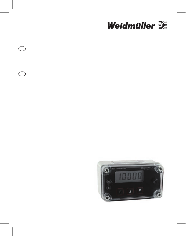
Mann Series LPD450F
P
Switch positions (shown in correct position for installation).
Page 8

• Calibration
Buy: www.ValinOnline.com | Phone 844-385-3099 | Email: CustomerService@valin.com
General
The LPD450F is factor y calibrated. You should not have to recalibrate the
unit before installation.
Allow the instrument 15 minutes of powered operation (to reach a
stable temperature) before calibration. During calibration allow a few
seconds for signals to stabilise before accepting the value.
Equipment requirements
A suitable 4-20 mA current source
•
Input calibration procedure
When the display shows Action/Description
Connec t the cur rent source to the in puts an d set to 4.0 0 mA.
Put the r un/cali brate sw itch in ca librate p ositi on, selec t setup m ode.
CALb
CALn
CALy
InH=
UPCn
UPCy
Press P
Press Å
Press P three tim es
Set the cu rrent source to 2 0.00 m A
Press P three tim es
Press Å
Press P
 Loading...