

Weidmuller IE-SW-VL16T-14TX-2ST, IE-SW-VL16-16TX, IE-SW-VL16T-14TX-2SC, IE-SW-VL16-14TX-2ST, IE-SW-VL16T-16TX Hardware Installation Manual
...
Unmanaged Fast Ethernet Switch
ValueLine
IE-SW-VL16 Series
Hardware Installation Guide
8th Edition, March 2018
1243330000/07/04.18
Important note:
This document and additional product information can be
downloaded using following link:
http://www.weidmueller.com
► Select Product Catalogue
Select „Active Industrial Ethernet “
Select „ValueLine unmanaged Switches “
Select Product model
Click and expand section „Downloads “
Download needed software or documentation
Copyright Notice
Copyright 2018 Weidmüller Interface GmbH & Co. KG
All rights reserved.
Reproduction without permission is prohibited.

Overview
ATTENTION
subject to the following two conditions: (1) This device may not
The IE-SW-VL16 series of 16-port smart Ethernet switches provides an
economical solution for your Ethernet connections. As a bonus, the
built-in smart alarm function helps system maintainers monitor the health
of your Ethernet network.
IE-SW-VL16 series is available with an operating temperature range of 0
to 60°C or optional with extended operating temperature range from -40
to 75°C. The devices are designed to withstand a high degree of vibration
and shock. The rugged hardware design makes IE-SW-VL16 series
perfect for ensuring that your Ethernet equipment can withstand critical
industrial applications, such as in hazardous locations (Class 1 Division
2/ Zone 2), and complies with FCC, UL and CE Standards.
This device complies with part 15 of FCC Rules. Operation is
cause harmful interference, and (2) this device must accept
any interference received, including interference that may
cause undesired operation.
Package Checklist
Your Ethernet Switch is shipped with the following items. If any of these
items is missing or damaged, please contact your Weidmüller customer
service for assistance.
Ethernet Switch
Protective caps for unused ports
Hardware Installation Guide (printed)
Features
High Performance Network Switching Technology
10/100BaseT(X) (RJ45), 100BaseFX (SC/ST type, Multimode)
IEEE 802.3/802.3u/802.3x
Store and Forward switching process type, with 4K address entries
10/100M, Full/Half-Duplex, MDI/MDIX auto-sensing
Industrial Grade Reliablity
Power failure, port break alarm by relay output
Redundant dual DC power inputs
Broadcast storm protection to prevent network devices from crashing
Rugged Design
IP30, rugged high-strength case
DIN-Rail or panel mounting ability
- 2 -
Panel Layout
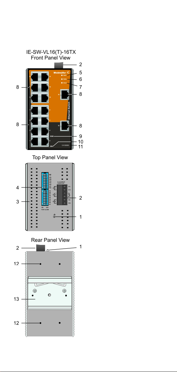
IE-SW-VL16(T)-16TX
1. Grounding screw
2. Terminal block for power input P1/P2
3. Heat dissipation orifices
4. DIP Switches
5. Power input PWR1 LED
6. Power input PWR2 LED
7. Fault LED
8. 10/100BaseT(X) Port
9. TP port’s 100 Mbps LED
10. TP port’s 10 Mbps LED
11. Article number
12. Screw hole for wall mounting kit
13. DIN-Rail Kit
- 3 -
Panel Layout
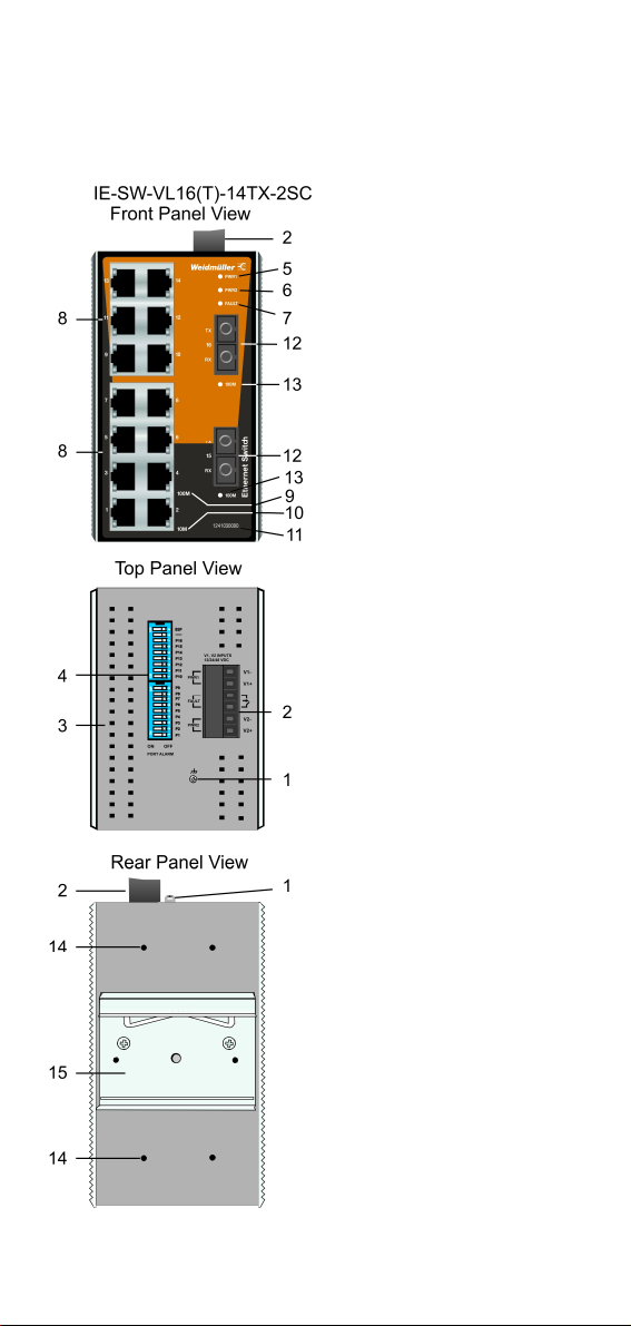
IE-SW-VL16(T)-14TX-2SC
1. Grounding screw
2. Terminal block for power input P1/P2
3. Heat dissipation orifices
4. DIP Switches
5. Power input PWR1 LED
6. Power input PWR2 LED
7. Fault LED
8. 10/100BaseT(X) Port
9. TP port’s 100 Mbps LED
10. TP port’s 10 Mbps LED
11. Article number
12. 100BaseFX Port
13. FX port’s 100 Mbps LED
14. Screw hole for wall mounting kit
15. DIN-Rail Kit
- 4 -
Panel Layout
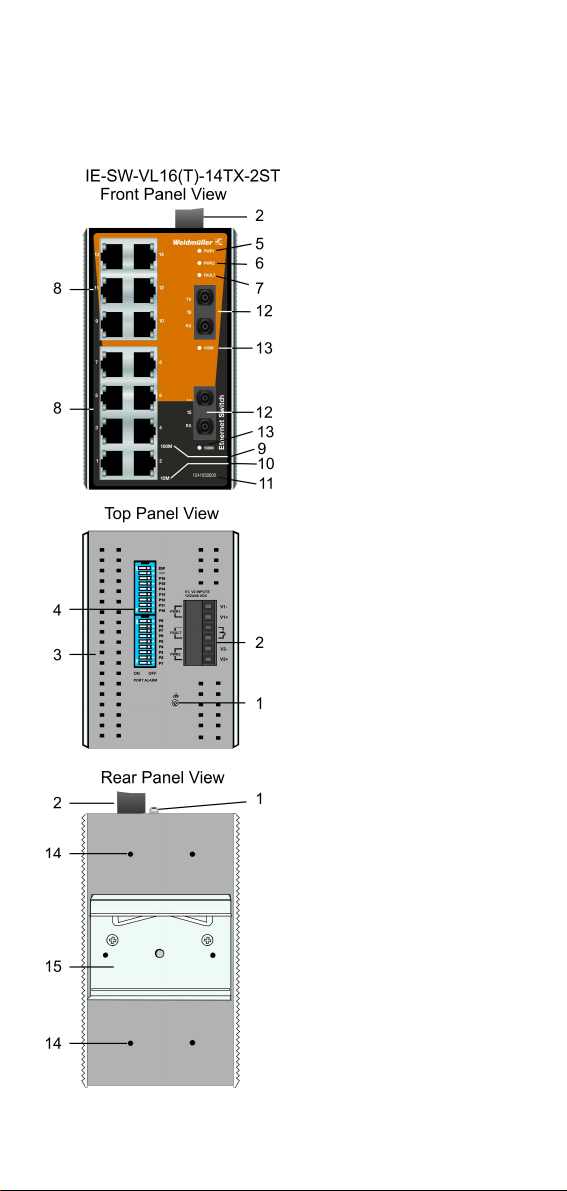
IE-SW-VL16(T)-14TX-2ST
1. Grounding screw
2. Terminal block for power input P1/P2
3. Heat dissipation orifices
4. DIP Switches
5. Power input PWR1 LED
6. Power input PWR2 LED
7. Fault LED
8. 10/100BaseT(X) Port
9. TP port’s 100 Mbps LED
10. TP port’s 10 Mbps LED
11. Article number
12. 100BaseFX Port
13. FX port’s 100 Mbps LED
14. Screw hole for wall mounting kit
15. DIN-Rail Kit
- 5 -
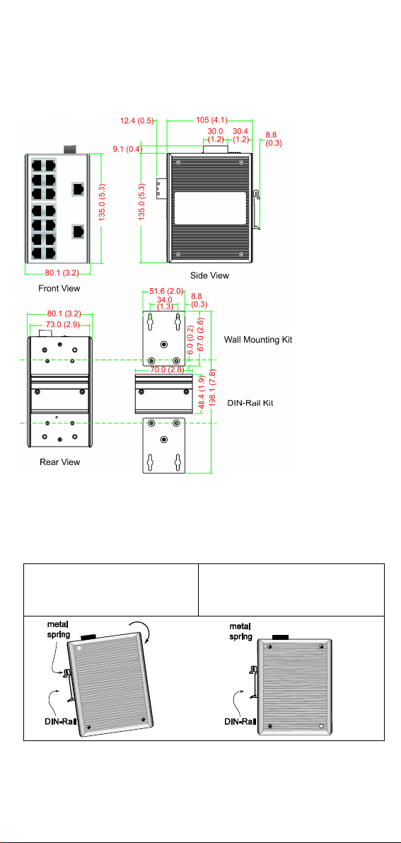
Mounting Dimensions
STEP 1
STEP 2
Units: mm (inch)
DIN-Rail Mounting
The aluminum DIN-rail attachment plate should already be fixed to the
back panel of the Ethernet Switch when you take it out of the box. If you
need to reattach the DIN-rail attachment plate, make sure the stiff metal
spring is situated towards the top, as shown in the figures below.
To remove the DIN-rail from the Ethernet Switch, simply reverse Steps 1
and 2.
:
Insert the top of the DIN-Rail into
the slot just below the stiff metal
spring.
:
The DIN-Rail attachment unit will
snap into place as shown below.
- 6 -
 Loading...