

Weidmuller IE-SW-VL09T-6TX-3SC Hardware Installation Manual

Ethernet Switch – Value Line
IE-SW-VL09T-6TX-3SC (Unmanaged)
Hardware Installation Guide
First Edition, December 2010
124098_0000/00/12.10
Please note:
This document and any further product information if available - can be downloaded at the internet link:
http://www.weidmueller.com/downloads
Copyright Notice
Copyright © 2010 Weidmüller Interface GmbH & Co. KG
All rights reserved.
Reproduction without permission is prohibited.

Overview
The switch IE-SW-VL09T-6TX-3SC with 9 Copper-and 3 SC-Fiber-Ports
provides an economical solution for your Ethernet connections. As an added
bonus, the built-in smart alarm function helps system maintainers monitor the
health of your Ethernet network.
This Ethernet switch has a wide operating temperature range of -40 to 75°C,
and is designed to withstand a high degree of vibration and shock. The rugged
hardware design makes it perfect for ensuring that your Ethernet equipment
can withstand critical industrial applications, and complies with FCC and CE
Standards.
Package Checklist
The device is shipped with the following items. If any of these items is missing
or damaged, please contact your Weidmüller customer service for assistance.
y 1 Ethernet Switch
y Hardware Installation Guide
y Protective caps for unused ports
Features
High Performance Network Switching Technology
y 10/100BaseT(X) (RJ45), 100BaseFX (SC/ST-type, Multi/Single mode)
y IEEE802.3/802.3u/802.3x
y Store and Forward switching process type, with 1024 address entries
y 10/100M, Full/Half-Duplex, MDI/MDIX auto-sensing
Industrial Grade Reliablity
y Power failure, port break alarm by relay output
y Redundant dual DC power inputs
Rugged Design
y Extended operating temperature from -40 to 75ºC
y IP30, rugged high-strength case
y DIN-rail or panel mounting ability
WARNING
The power for this product is intended to be supplied by a Listed
Power Supply, with output marked LPS, and rated to deliver 12 to
48 VDC at a maximum of 0.6A.
The DC jack should be used with an LPS unit that is rated to
deliver 12 to 48 VDC at a minimum of 1.1A. The product should
not be disassembled by operators or service people.
- 2 -

Panel Layout of
IE-SW-VL09T-6TX-3SC
1. Grounding screw
2. Terminal block for power
inputs PWR1/PWR2 and
relay output
3. Heat dissipation orifices
4. DIP switches
5. Power input PWR1 LED
6. Power input PWR2 LED
7. Fault LED
8. 10/100BaseT(X) Port
9. TP port’s 100 Mbps LED
10. TP port’s 10 Mbps LED
11. Article Number
12. 100BaseFX Port
13. Screw holes for wall
mounting kit
14. DIN-Rail Kit
15. 100 Mbps LED for FX port 7
16. 100 Mbps LED for FX port 8
17. 100 Mbps LED for FX port 9
IE-SW-VL09T-6TX-3SC
Front Panel
Top Panel View
Rear Panel View
- 3 -
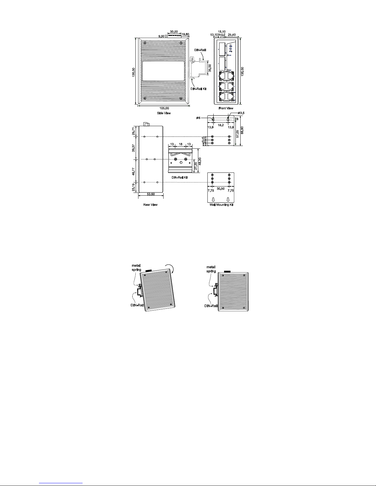
Mounting Dimensions (unit = mm)
DIN-Rail Mounting
The aluminum DIN-Rail attachment plate should already be fixed to the back
panel of the Ethernet Switch when you take it out of the box. If you need to
reattach the DIN-Rail attachment plate, make sure the stiff metal spring is
situated towards the top, as shown in the figures below.
STEP 1:
Insert the top of the DIN-Rail into the
slot just below the stiff metal spring.
STEP 2:
The DIN-Rail attachment unit will
snap into place as shown below.
To remove the Ethernet Switch from the DIN-Rail, simply reverse Steps 1 and
2 above.
- 4 -
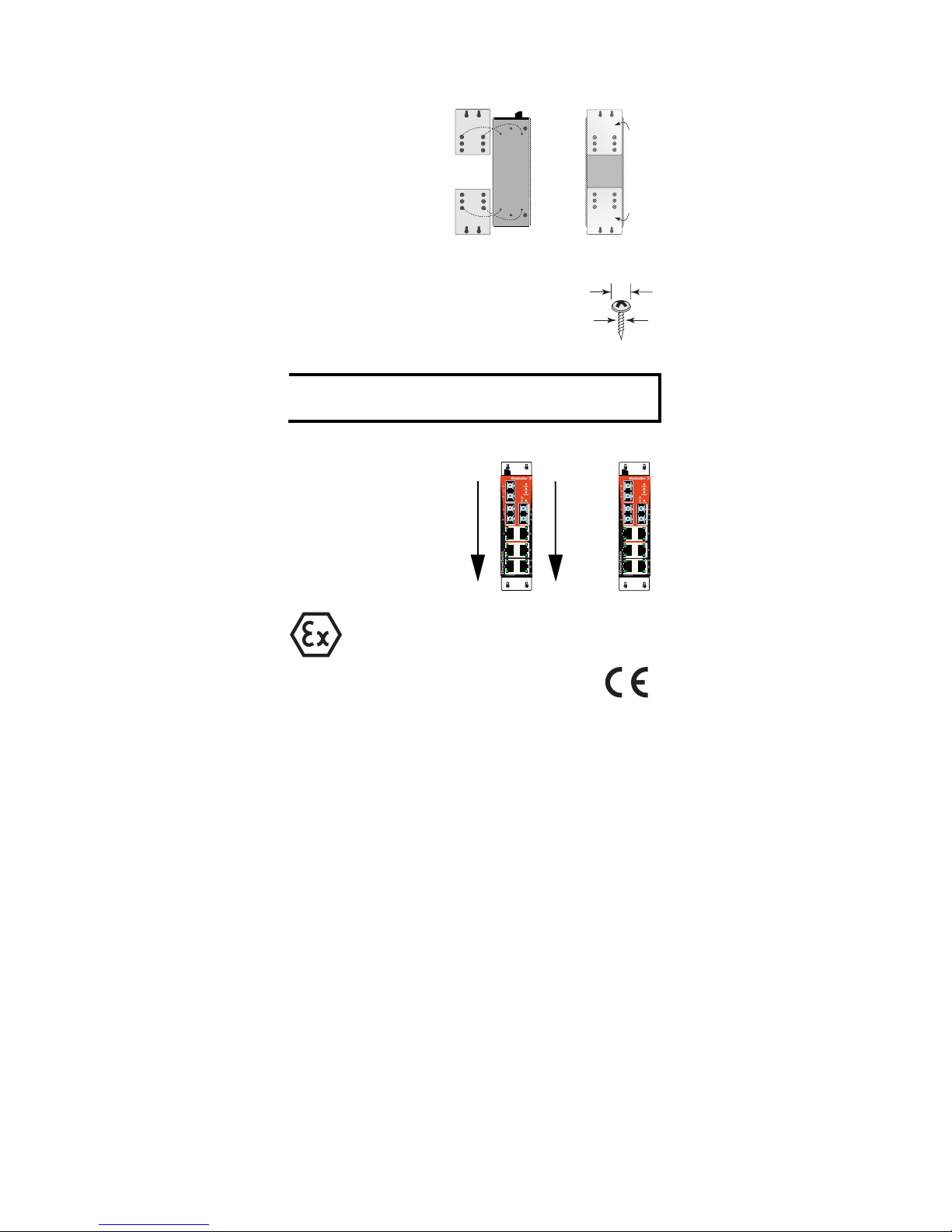
Wall Mounting (optional)
For some applications, you will find it convenient to mount the device on the
wall, as illustrated below.
STEP 1:
Remove the aluminum
DIN-Rail attachment plate from
the switch’s rear panel, and then
attach the wall mount plates, as
shown in the diagram below.
⇒
top
plate
bottom
plate
STEP 2:
Mounting the device on the wall requires 4 screws. Use the
switch, with wall mount plates attached, as a guide to mark
the correct locations of the 4 screws. The heads of the
screws should be less than 6.0 mm in diameter, and the
shafts should be less than 3.5 mm in diameter, as shown in
the figure at the right.
6.0 mm
3.5 mm
NOTE
Before tightening screws into the wall, make sure the screw head and
shank size are suitable by inserting the screw into one of the keyholeshaped apertures of the Wall Mounting Plates.
Do not screw the screws in all the way—leave about 2 mm to allow room for
sliding the wall mount panel between the wall and the screws.
STEP 3:
Once the screws are fixed in the
wall, insert the four screw heads
through the large parts of the
keyhole-shaped apertures, and then
slide the Ethernet switch
downwards, as indicated. Tighten
the four screws for added stability.
⇒
II 3G
ATEX Information
1. Certificate number DEMKO 08 ATEX 0717913X
2. Ambient range: -40°C ≤ Tamb ≤ +75°C
3. Certification String: EX nC nL IIC T4
4. Applicable standards: EN60079-0: 2006, EN60079-15:2005
5. The conditions of safe usage:
a. The Ethernet Communication Devices are intended for mounting in an
IP54 enclosure and used in an area of not more than pollution degree 2 as
defined by IEC60664-1
b. Conductors suitable for use in an ambient temperature of 95°C must be
used for the Power Supply Terminal.
- 5 -
 Loading...