

Weidmuller IE-SW-VL08M User Manual

Industrial Fast Ethernet Switch
Manual IE-SW-VL08M Series
First Edition, January 2011
1243130000/00/01.11

Industrial Ethernet Switch
Manual IE-SW-VL08M Series
The software described in this m a nual is f urn ished under a li cense a greem ent and may be used only in ac cordance
with the terms of that agreement.
Copyright Notice
Copyright © 2010 Weidmüller Interface GmbH &Co. KG.
All rights reserved.
Reproduction without permi ssion is pr ohibited.
Disclaimer
Information in this document is subject to change without notice and does not represent a commitment on the part
of Weidmüller.
Weidmüller provides this document “as is,” without warranty of any kind, either expressed or im pl ied, i ncl uding,
but not limited to, its particular purpose. Weidmüller reserves the right to make improvements and/or changes to
this manual, or to the products and/or the programs described in this manual, at any time.
Information provided in this manual is intended to be accurate and reliable. However, Weidmüller assumes no
responsibility for its use, or for any infringements on the rights of third parties that may result from its use.
This product might include unintentional technical or typographical errors. Changes are periodically made to the
information herein to correct such errors, and the se changes are incorpor ated into new editions of the publication.
Contact Information
Weidmüller Interface GmbH & Co. KG
Postbox 3030
32760 Detmold
Klingenbergstraße 16
32758 Detmold
Germany
Phone: +49(0) 5231 14-0
Fax:+49(0) 5231 14-2083
E-Mail
info@weidmueller.com
Internet www.weidmueller.com

Table of Contents
Chapter 1 Introduction ...............................................................................................1-1
Overview.............................................................................................................................. 1-2
Package Checklist................................................................................................................. 1-2
Features ................................................................................................................................ 1-2
Chapter 2 Getting Started ..........................................................................................2-1
RS-232 Console Configuration (115200, None, 8, 1, VT100) ............................................. 2-2
Configuration Using a T elnet Console..................................................................................2-5
Configuration Using a Web Browser.................................................................................... 2-7
Disabling T elnet and Browser Access .................................................................................. 2-9
Chapter 3 Featured Functions...................................................................................3-1
Configuring Basic Settings................................................................................................... 3-1
System Identification................................................................................................. 3-1
Password ................................................................................................................... 3-2
Accessible IP............................................................................................................. 3-3
Port............................................................................................................................ 3-4
Network................................................................................................................................ 3-5
Time.......................................................................................................................... 3-8
Turbo Ring DIP Switch........................................................................................... 3-10
System File Update: By Remote TFTP................................................................... 3-13
System File Update: By Local Import/Export......................................................... 3-14
System File Update: By Backup Media.................................................................. 3-15
Restart ..................................................................................................................... 3-15
Factory Default........................................................................................................ 3-15
Configuring SNMP............................................................................................................. 3-16
SNMP Read/Write Settings..................................................................................... 3-17
Trap Settings ........................................................................................................... 3-19
Private MIB information......................................................................................... 3-20
Using Communication Redundancy................................................................................... 3-20
The Turbo Ring Concept......................................................................................... 3-21
Configuring “Turbo Ring” and “Turbo Ring V2”................................................... 3-25
The Turbo Chain Concept....................................................................................... 3-31
Configuring “Turbo Chain”..................................................................................... 3-32
The STP/RSTP Concept.......................................................................................... 3-33
Configuring STP/RSTP........................................................................................... 3-38
Using Traffic Prioritization................................................................................................. 3-41
The Traffic Prioritization Concept.......................................................................... 3-41
Configuring Traffic Prioritization........................................................................... 3-44
Using Virtual LANs............................................................................................................ 3-46
The Virtual LAN (VLAN) Concept........................................................................ 3-46
Sample Applications of VLANs using the IE-SW-VL-08M................................... 3-49
Configuring Virtual LAN........................................................................................ 3-50
Using Multicast Filtering.................................................................................................... 3-52
The Concept of Multicast Filtering......................................................................... 3-52
Configuring IGMP Snooping.................................................................................. 3-55
Static Multicast MAC.............................................................................................. 3-57
Configuring GMRP................................................................................................. 3-58

GMRP Table ........................................................................................................... 3-58
Using Rate Limiting........................................................................................................... 3-58
Configuring Rate Limiting...................................................................................... 3-59
Using Auto Warning........................................................................................................... 3-60
Configuring Email Warning.................................................................................... 3-60
Email Warning Events Settings............................................................................... 3-61
Email Settings ......................................................................................................... 3-62
Configuring Relay Warning.................................................................................... 3-63
Relay Warning Events Settings............................................................................... 3-64
Relay Warning List ................................................................................................. 3-65
Using Line-Swap-Fast-Recovery........................................................................................ 3-65
Configuring Line-Swap Fast Recovery................................................................... 3-66
Using Set Device IP............................................................................................................ 3-66
Configuring Set Device IP ...................................................................................... 3-67
Using Diagnosis.................................................................................................................. 3-69
Mirror Port .............................................................................................................. 3-69
Ping ......................................................................................................................... 3-70
LLDP....................................................................................................................... 3-70
Using the Monitor............................................................................................................... 3-72
Monitor by Switch................................................................................................... 3-72
Monitor by Port....................................................................................................... 3-72
Using the MAC Address Tabl e........................................................................................... 3-73
Using Event Log................................................................................................................. 3-74
Using Syslog....................................................................................................................... 3-74
Chapter 4 Weidmüller Switch Configuration Utility................................................ A-1
Starting Ethernet Switch Configuration Utility................................................................... A-2
Broadcast Search................................................................................................................. A-2
Search by IP address............................................................................................................ A-3
Upgrade Firmware............................................................................................................... A-4
Modify IP Address............................................................................................................... A-5
Export Configuration........................................................................................................... A-5
Import Configuration........................................................................................................... A-7
Unlock the Ethernet Switch................................................................................................. A-8
Appendix A MIB Groups.............................................................................................A-10
Appendix B Modbus/TCP Map ..................................................................................... B-1
Modbus Information.............................................................................................................B-1

1
1
Chapter 1 Introduction
Welcome to the Weidmüller Industrial Ethernet Switch IE-SW-VL08M , which is designed
especially for connecting Ethernet-enabled devices in industrial field applications.
The following topics are covered in this chapter:
Over view
Package Checklist
Features

IE-SW-VL08M Series User’s Manual Introduction
1-2
Overview
Weidmüller Industrial Ethernet Switches come with a suite of useful maintenance and monitoring
functions, and is designed to provide smooth and reliable operation in harsh industri al environments.
You will find that Weidmüller Industrial Ethernet Switches establish a new industrial Ethernet
benchmark. The switches are excellent for keeping automation systems running continuously, are
ideal for sending status reports to help prevent system damages and losses, are a great tool for
mastering your industrial Ethernet networks, and are well-suited for use with industrial device
control networks.
Package Checklist
The Industrial Ethernet Switch IE-SW-VL08M is shipped with the following items:
y 1 Industrial Ethernet Switch IE-SW-VL08M
y Hardware Installation Guide
y CD-ROM with Manual and Windows Utility
y RJ45 to DB9 Console port cable
y Protective caps for unused ports
NOTE: Please notify your sales representative if any of the above items are missing or
damaged.
Features
y IPv6 Ready logo awarded (IPv6 Logo Committee certified).
y DHCP Option 82 for IP address assignment with different policies.
y Modbus/TCP industrial Ethernet protocol supported.
y Turbo Ring and Turbo Chain (recovery time < 20 ms at full load) and RSTP/STP (IEEE
802.1w/D).
y IGMP snooping and GMRP for filtering multicast traffic.
y Port-based VLAN, IEEE 802.1Q VLAN, and GVRP to ease network planning.
y Supports QoS Æ IEEE 802.1p and TOS/DiffServ to increase determinism.
y SNMPv1/v2c/v3 for different levels of network management.
y RMON for efficient network monitoring and proactive capability.
y Bandwidth management prevents unpredictable network status.
y Port mirroring for online debugging.
y Automatic warning by exception through e-mail, relay output.
y Digital inputs to integrate sensors and alarms with IP networks.

2
2
Chapter 2 Getting Started
This chapter explains how to access your Industrial Ethernet Switch for the first time. There are
three ways to access the switch: serial console, Telnet console, and web browser. The serial console
connection method, which requires using a short serial cable to connect the switch to a PC’s COM
port, can be used if you do not know the switch’s IP address. The Telnet console and web browser
connection methods can be used to access Industrial Ethernet Switches over an Ethernet LAN, or
over the Internet.
The following topics are covered:
RS-232 Console Configurat ion (115200, None, 8, 1, VT100)
Configuration Using a Telnet Console
Configuration Using a Web Browser
Disabling Telnet and Browser Access

IE-SW-VL08M Series User’s Manual Getting Started
2-2
RS-232 Console Configuration (115200, None, 8, 1, VT100)
NOTE
Connection Caution!
1. You cannot connect to the IE-SW using serial console and Telnet simultaneously.
2. You can connect to the IE-SW using a web browser and serial console simultaneously, or
using a web browser and Telnet simultaneously.
3. Recommendation: When you are connecting to the IE-SW using a web browser, do NOT
simultaneously connect using either a serial console or by Telnet.
By following this advice, you can maintain better control over how your Industrial Ethernet Switch
is managed.
NOTE
We recommend using Hyper Terminal Tool, which is alrea dy instal l e d un der Wi nd ows XP.
Before running Hyper Termi nal To ol use an RJ45 to DB9-F (or R J45 to DB25-F) cable to connect
the Ethernet Switch’s RS-232 Console port to your PC’s COM port (generally COM1 or COM2,
depending on how your system is set up).
After installing Hyper Terminal Tool, do the following to access the RS-232 Console utility.
1. From the Windows desktop, click Start Æ Programs Æ Accessories Æ
CommunicationsÆHyper Terminal.
2. Start Hyper Terminal and enter a name of your choosing for the new connection. Select the
appropriate COM port for console connection in the “New Connection” window.
IE-SW-VL08M Series User’s Manual Getting Started
2-3
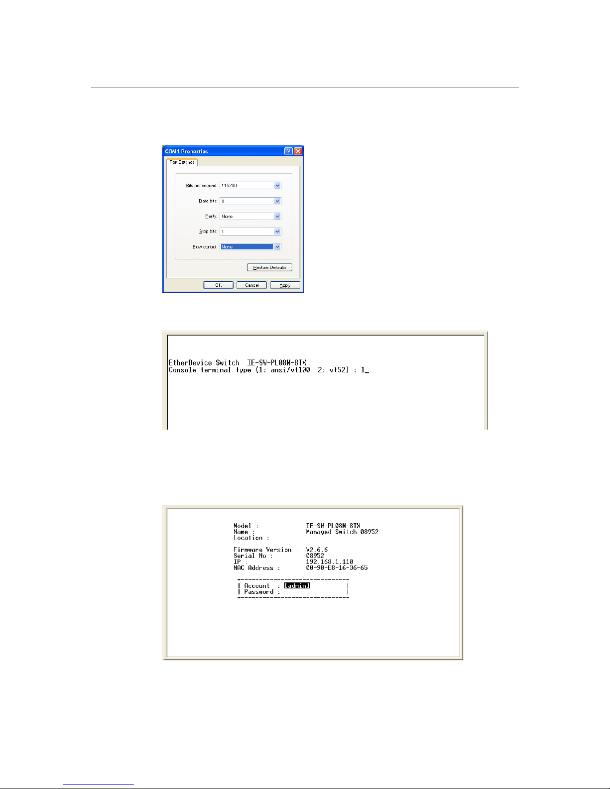
3. The Communication Parameter for console connection are:
115200 for Baud Rate, 8 for Data Bits, None for Parity, 1 for Stop bits and None for Flow
Control. Click OK to continue.
4. Type 1 to select ansi/VT 100 terminal type, and then press Enter.
5. The Console login screen will appear. Press Enter to open the Account pop-up selector and
then select either admin or user. Use the keyboard’s down arrow to move the cursor to the
Password field, enter the default Console Password “Detmold” (this is the same as the Web
Browser password; leave the Password field blank if a console pa ssword has not bee n set), and
then press Enter.

IE-SW-VL08M Series User’s Manual Getting Started
2-4
6. The IE-SW-VL08M’s Main Menu will be displayed
7. The Console login screen will be displayed. Press Enter to open the Account pop-up selector
and then select either admin or user. Use the keyboar d’s down arro w t o move the cursor to the
Password field, enter the Console Password (this is the same as the Web Browser password;
leave the Password field blank if a console password has not been set), and then press Enter.
8. The IE-SW-VL08M’s Main Menu will be displayed.

IE-SW-VL08M Series User’s Manual Getting Started
2-5
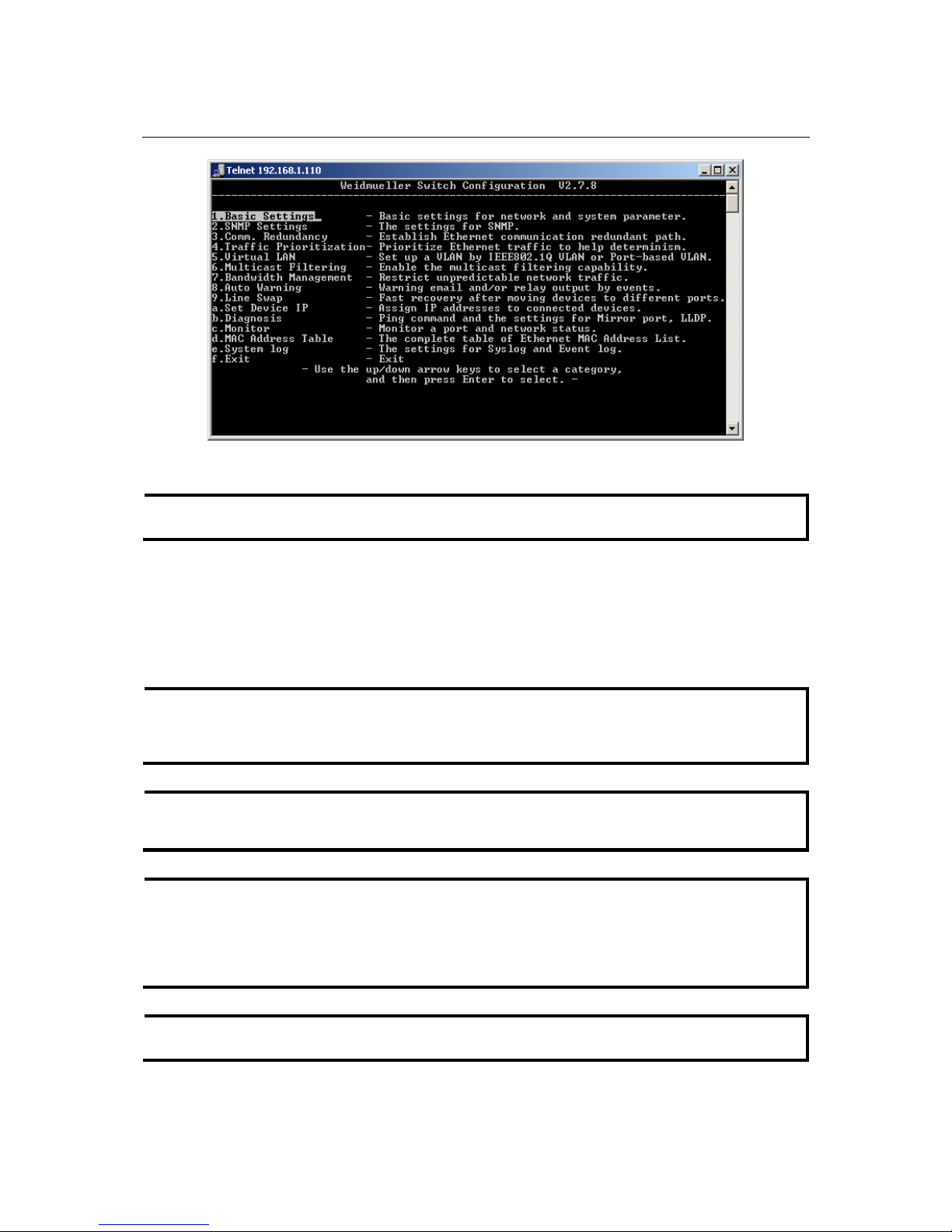
9. After entering the Main Menu, use the following keys to move the cursor, and to select options.
Key Function
Up/Down/Left/Right arrows, or Tab Move the onscreen cursor
Enter Display & select options
Space Toggle options
Esc Previous Menu
Configuration Using a Telnet Console
You may use Telnet to access the IE-SW-VL08M’s console utility over a network. To be able to
access the IE-SW-VL08M-’s functions over the network (us i ng Telnet or a Web Browser) from a
PC host that is connected to the same LAN as the IE-SW-VL08M, you need to m ake sure that the PC
host and the IE-SW-VL08M are on the same logical sub network. To do this, check your PC host’s
IP address and netmask. By default, the IE-SW-VL08M’s IP address is 192.168.1.110 and the
netmask is 255.255.255.0 (for a Class C network). If you do not change these values, and your PC
host’s netmask is 255.255.255 .0, then its IP add ress must have the form 192.16 8.1.xxx. On t he other
hand, if your PC host’s netmask is 255.255.255.0, then its IP address must have the form
192.168.1.xxx.
NOTE
To use the IE-SW-VL08M’s management and monitoring functions from a PC host connected to
the same LAN as the IE-SW-VL08M’, you must make sure that the PC host and the
IE-SW-VL08M’s are on the same logical sub network.
The IE-SW-VL08M’s default IP address is 192.168.1.110.
Perform the following steps to access the console utility via Telnet.
1. Telnet to the IE-SW-VL08M’s IP address from the Windows Run window (or from the command
prompt).
NOTE
Before accessing the console utility via Telnet, first connect one of the IE-SW-VL08M’s RJ45
Ethernet ports to your Ethernet LAN, or connect directly to your PC’s Ethernet NIC. You can
establish a connection with either a straight-through or cross-over Ethernet cable. If you have
difficulty connecting, refer to the Auto MDI/MDI-X Connection section from the Hardware
installation Guide for more information about the different types of Ethernet cables and ports.

IE-SW-VL08M Series User’s Manual Getting Started
2-6
2. Type 1 to choose ansi/vt100, and then press Enter.
3. The Console login screen will be displayed. Press Enter to open the Account pop-up selector and then
select either admin or user. Use the keyboard’s down arrow to move the cursor to the Password field,
enter the Console Password (this is the same as the Web Browser password; leave the Password field
blank if a console password has not been set), and then press Enter.
4. The IE-SW-VL08M’s Main Menu will be displayed. (NOTE: To modify the appearance of the
PComm Terminal Emulator window, select Font… under the Edit menu, and then choose the desired
formatting options.)
IE-SW-VL08M Series User’s Manual Getting Started
2-7
Configuration Using a Web Browser
The IE-SW-VL08M’s web browser interface provides a convenient way to modify the switch’s
configuration and access the built-in monitoring and network administration functions. The
recommended web browser is Microsoft Internet Explorer 5.5 or 6.0 with JVM (Java Virtual
Machine) installed.
NOTE
To use the Ethernet Switch’s management and monitoring functions from a PC host connected to
the same LAN as the IE-SW-VL08M’, you must make sure that the PC host and the Ethernet
switch are on the same logical sub network.
NOTE
If the Ethernet Switch is configured for other VLAN settings, you must make sure your PC host is
on the Management VLAN.
NOTE
Before accessing the IE-SW-VL08M’s web browser interface, first connect one of the device’s
RJ45 Ethernet ports to your Ethernet LAN, or directly to your PC’s Ethernet NIC. You can
establish a connection with either a straight-through or cross-over Ethernet cable. If you have
difficulty connecting, refer to the Auto MDI/MDI-X Connection section from the Hardware
installation Guide for more information about the different types of Ethernet cables and ports.
NOTE
The IE-SW-VL08M’s default IP is 192.168.1.110.
NOTE
The Telnet Console looks and operates in precisely the same manner as the RS-232 Console.
IE-SW-VL08M Series User’s Manual Getting Started
2-8
Perform the following steps to access the web browser interface.
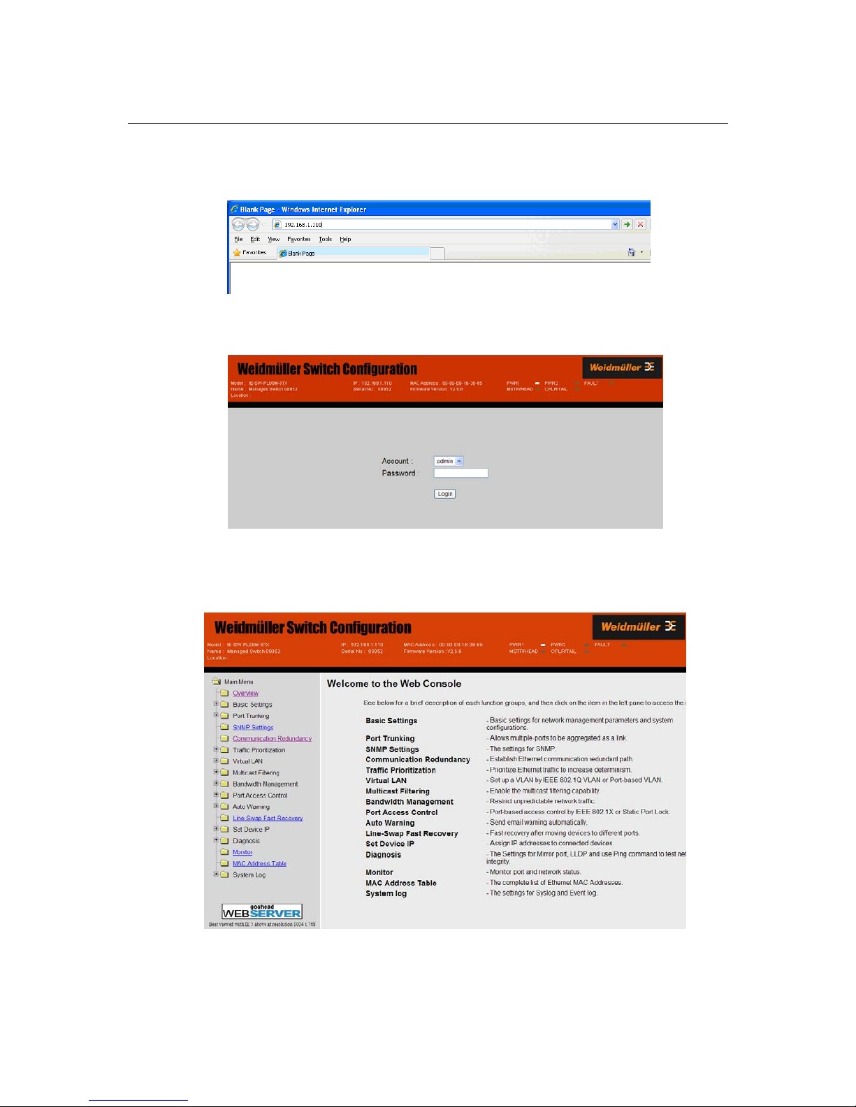
1. Open Internet Explorer and type the IE-SW-VL08M’s IP address in the Address field. Press
Enter to establish the connection.
2. The web login page will be displayed. Select the login account (Admin or User) and enter the
Password (this is the same as the Console password), and then click Login to continue. Leave
the Password field blank if a password has not been set.
You may need to wait a fe w mom ents for t he web page to be downl oaded t o your c omput er. Use t he
menu tree on the left side of the window to open the function pages to access each of the Ethernet
switch functions.

IE-SW-VL08M Series User’s Manual Getting Started
2-9
Disabling Telnet and Browser Access
If you are connecting the IE-SW-VL08M to a public network, but do not intend to use its
management functions over the network, then we suggest disabling both Telnet Console and Web
Configuration from the RS-232 Console’s Basic Settings Æ System Identification page, as
shown in the following figure.
NOTE
If you are connecting the IE-SW-VL08M to a public network, but do not intend to use its
management functions over the netw ork, t hen we s uggest disablin g both Telnet Consol e and Web
Configuration.

3
3
Chapter 3 Featured Functions
This chapter explains how to access a Weidmueller Ethernet switch’s various configuration,
monitoring, and administration functions. There are three ways to access these functions: serial
console, Telnet console, and web browser. The serial console connection method, which requires
using a short serial cable to connect the switch to a PC’s COM port, can be used if you do not know
the IE-SW’s IP address. The Telnet console and web browser connection methods can be used to
access the IE-SW over an Ethernet LAN, or over the Internet.
The Web Console is the most user-friendly way to configure your Ethernet Switch. In this chapter,
we use the Web Console interface to introduce the device functions. There are only a few differences
between the Web Console, Serial Console, and Telnet Console access methods.
The following topics are covered in this chapter:
Configuring Basic Settings
Configuring Basic Settings
Network
Configuring SNMP
Using Communication Redundancy
Using Traffic Prioritization
Using Virtual LANs
Using Multicast Filtering
Using Rate Limiting
Using Auto Warning
Using Line-Swap-Fast-Recovery
Using Set Device IP
Using Diagnosis
Using the Monitor
Using the MAC Address Table
Using Event Log
Using Syslog

Configuring Basic Settings
The Basic Settings group includes the most commonly used settings required by administrators to
maintain and control the Ethernet Switch.
System Identification
The system identification items are displayed at the top of the web page, and will be included in
alarm emails. Setting system identification items makes it easier to identify the different switches
connected to your network.
Switch Name
Setting Description Factory Default
Max. 30
Characters
This option is useful for specifying t he role or
application of different IE-Swit c h uni t s.
E.g., Factory Switch 1.
Industrial Ethernet
Switch [Serial No. of this
switch]
Switch Location
Setting Description Factory Default
Max. 80
Characters
To specify the location of different IE-Switch
units. E.g., production line 1.
Switch Location
Switch Description
Setting Description Factory Default
Max. 30
Characters
Use this to record a more det aile d descript ion
of the Ethernet switch.
None
Maintainer Contact Info
Setting Description Factory Default
IE-SW-VL08M Series User’s Manual Featured Functions
3-2
Max.30
Characters
Use this to record contact information of the
person responsible for maintaining this
IE-SW-VL08M switch.
None
Web Configuration
Setting Description Factory Default
Disable / http or https /
https only
You can select disable, or accept both http and
https, or https only, from the web console
http or https
Web Auto-logout (s)
Setting Description Factory Default
60 to 86400 (seconds)
Disable or extend the auto-logout time for the
web management console.
0 (disable)
Age time (s)
Setting Description Factory Default
15 to 3825 (seconds)
The length of time that a MAC address entry
can remain in the Weidmueller switch. When
an entry reaches its aging time, it “ages out”
and is purged from the switch, effectively
cancelling frame forwarding to that specific
port.
300
Password
The Weidmueller switch provides two levels of access privileges: admin privilege gives read/write
access to all switch configuration parameters; user privilege provides read access only—you will be
able to view the configuration, but will not be able to make modifications.
ATTENTION
The IE-SW-VL08M’s default Password is set to “Detmold”.
If a Password is set, then you will be required to type the Password when logging into the RS-232
Console, Telnet Console, or Web Browser interface .
IE-SW-VL08M Series User’s Manual Featured Functions
3-3
Account
Setting Description Factory Default
admin admin privilege allows the user to modify
all device configurations.
user user privilege only allows viewing device
configurations.
admin
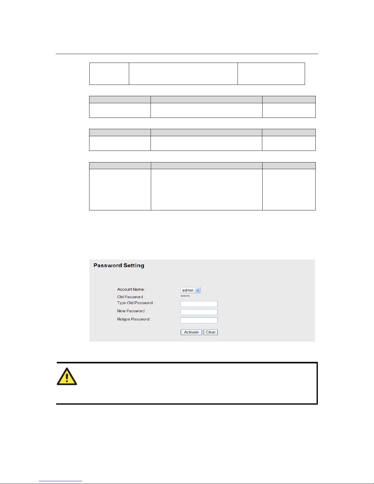
Password
Setting Description Factory Default
Old Password (Max.
16 Characters)
Type current password when changing the
password
None
New Password (Max.
16 Characters)
Type new password when changing the
password
None
Retype Password
(Max. 16 Characters)
If you type a new password in the
Password field, you will be required to
retype the password in the Retype new
password field before updating the new
password.
None
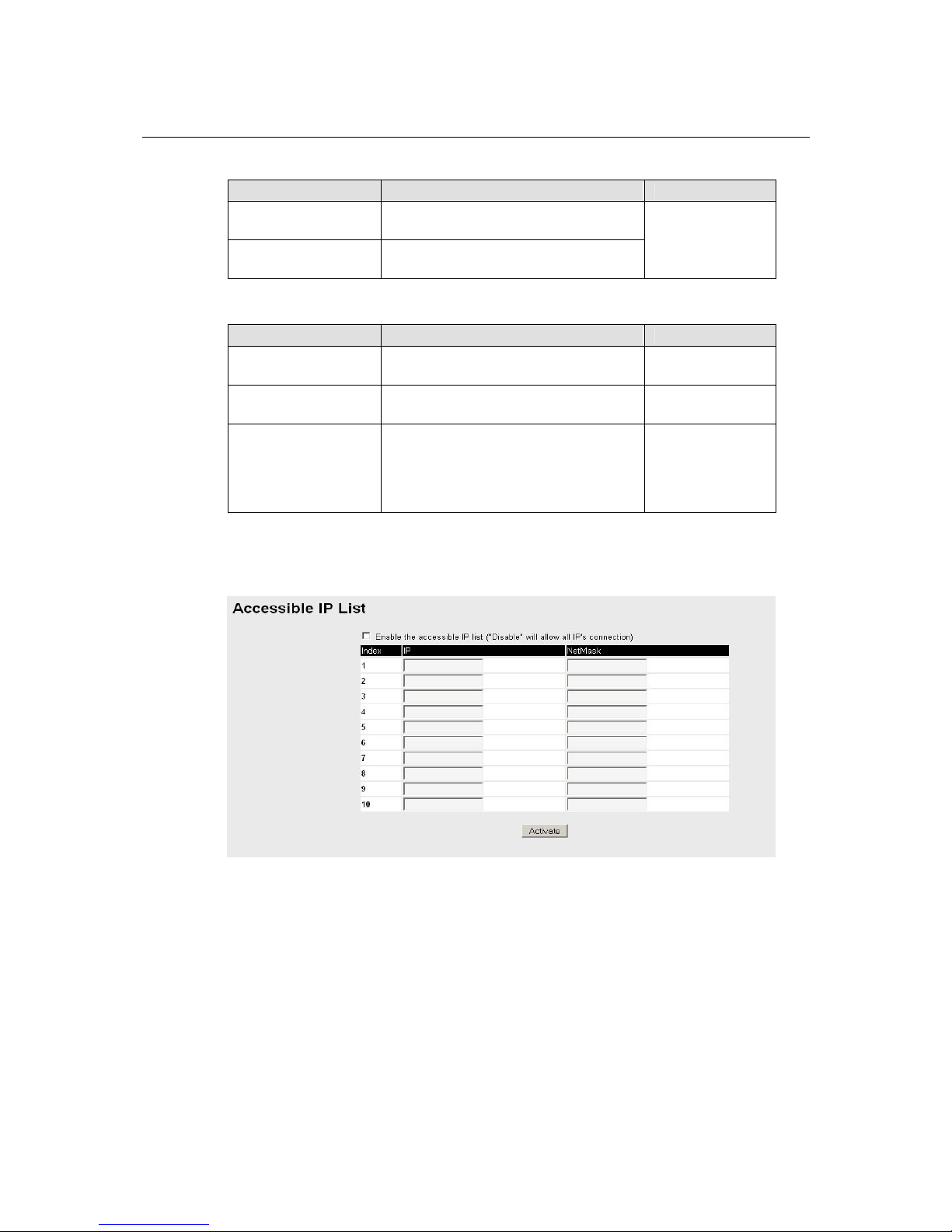
Accessible IP
An IP address-based filtering method to control access to Weidmueller switches.
Accessible IP Settings allows you to add or remove Legal remote host IP addresses to prevent
unauthorized access. Access to the Weidmueller switch is controlled by IP addresses. That is, if a
host’s IP address is in the accessible IP table, the n the host will be allowed access to the device. You
can allow one of the following cases by setting this parameter
y Only one host with the specified IP address can access the IE-SW-VL08M
E.g., enter “192.168.1.1/255.255.255.255” to allow access to just the IP address 192.168.1.1.
y Any host on a specific sub network can access the IE-SW-VL08M
E.g., enter “192.168.1.0/255.255.255.0” to allow access to all IPs on the sub network defined by
this IP address/netmask combination.

IE-SW-VL08M Series User’s Manual Featured Functions
3-4
y Any host can access the IE-SW-VL08M
Disable this function by not selecting the Enable the accessible IP list checkbox.
The following table shows additional configuration examples:
Allowable Hosts Input format
Any host Disable
192.168.1.120 192.168.1.120 / 255.255.255.255
192.168.1.1 to 192.168.1.254 192.168.1.0 / 255.255.255.0
192.168.0.1 to 192.168.255.254 192.168.0.0 / 255.255.0.0
192.168.1.1 to 192.168.1.126 192.168.1.0 / 255.255.255.128
192.168.1.129 to 192.168.1.254 192.168.1.128 / 255.255.255.128
Port
Port settings are included to give the user cont rol over Po rt Access, Port Tran sm ission Speed, Flow
Control, and Port Type (MD I or MD IX). An e xpla nat ion of eac h co nfi gura t ion i tem i s giv en bel ow .
(NOTE: The user interface for the IE-SW-VL08M will show 8 ports.)
Enable
Setting Description Factory Default
checked Allows data transmission through the port.
unchecked Immediately shuts off port access.
disabled
ATTENTION
If a connected device or sub-network is wreaking havoc on the rest of the network, the Disable
option under Advanced Settings/Port gives the administrator a q uick way to imm ediately shut off
access through this port.

IE-SW-VL08M Series User’s Manual Featured Functions
3-5
Name
Setting Description Factory Default
Max. 63
Characters
Specify an alias for each port, and assist the
administrator in remembering important
information about the port.
E.g., PLC 1
None
Port Transmission Speed
Setting Description Factory Default
Auto
Allows the port to use the IEEE 802.3u protocol
to negotiate with connected devices. The port
and connected devices will determine the best
speed for that connection.
100M-Full
100M-Half
10M-Full
10M-Half
Choose one of these fixed speed options if the
Ethernet device at the other end has trouble
auto-negotiating for line speed.
Auto
FDX Flow Control
This setting enables or disables the flow control capability of this port when the port transmission
speed setting is on auto mode. The final result will be determined by the auto process between the
IE-SW-VL08M and the connected device.
Setting Description Factory Default
Enable
Enables the flow control capability of this port
when in auto-nego mode.
Disable
Disables the flow control capability of this port
when in auto-nego mode.
Disable
Port Type
Setting Description Factory Default
Auto
Allows the port to auto detect the port type of
the Ethernet device at the other end and change
the port type accordingly.
MDI
MDIX
Choose the MDI or MDIX option if the
Ethernet device at the other end has trouble
auto-negotiating for port type.
Auto
Network
The Network configuration allows users to configure both IPv4 and IPv6 parameters for
management access over the network. The IE-SW-VLxxM series supports both IPv4 and IPv6, and
can be managed through either of these address types.

IE-SW-VL08M Series User’s Manual Featured Functions
3-6
IPv4
The IPv4 settings include the switch’s IP address and subnet mask, as well as the IP address of the
default gateway. In addition, input cells are provided for the IP addresses of a 1st and 2nd DNS
server.
IPv6
IPv6 setting includes two distinct address types—Link-Local Unicast address and Global Unicast
address. A Link-Local address makes the switch accessible over IPv6 for all devices attached to the
same local subnet. To connect to a larger network with multiple segments, the switch must be
configured with a Global Unicast address.
See a brief explanation of each configuration item below.
Auto IP Configuration
Setting Description Factory Default
Disable Set up the IE-SW-VL08M’s IP address
manually.
By DHCP The IP address will be assigned automatically
by the network’s DHCP server.
By BOOTP The IP address will be assigned automatically
by the network’s BOOTP server.
Disable
Switch IP Address
Setting Description Factory Default
IP Address of the
IE-SW-VL08M
Identifies the IE-SW-VL08M on a TCP/IP
network.
192.168.127.253
IE-SW-VL08M Series User’s Manual Featured Functions
3-7
Switch Subnet Mask
Setting Description Factory Default
Subnet mask of the
IE-SW-VL08M
Identifies the type of network to which the
IE-SW-VL08M is connected (e.g., 255.255.0.0
for a Class B network, or 255.255.255.0 for a
Class C network).
255.255.255.0
Default Gateway
Setting Description Factory Default
Default Gateway of the
IE-SW-VL08M
The IP address of the router that connects the
LAN to an outside network.
None
DNS IP Address
Setting Description Factory Default
1st DNS Server’s
IP Address
The IP address of the DNS Server used by your
network.
None
2nd DNS Server’s
IP Address
The IP address of the DNS Server used by your
network. The IE-SW-VL08M will try to locate
the 2nd DNS Server if the 1st DNS Server fails
to connect.
None
Global Unicast Address Prefix (Prefix Length: 64 bits)
Setting Description Factory Default
Global Unicast Address
Prefix
The prefix value must be formatted according to
RFC 2373 “IPv6 Addressing Architecture,”
using 8 colon-separated 16-bit he xadeci mal
values. One double colon may be used in the
address to indicate the appropriate number of
zeros required to fill the undefined fields.
None
Global Unicast Address
Setting Description Factory Default
None Displays the IPv6 Global Unicast address. The
network portion of the Global Unicast address
can be configured by specifying the Global
Unicast Prefix and using a EUI-64 interface ID
in the low order 64 bits. The host portion of the
Global Unicast address is automatically
generated using the modified EUI-64 form of
the interface identifier (Switch’s MAC address)
None
Link-Local Address
Setting Description Factory Default
None The network portion of the Link-Local address
is FE80 and the host portion of Link-Local
address is automatically generated using the
modified EUI-64 from of the interface identifier
(Switch’s MAC address)
FE80: (EUI-64
form of the MAC
address)
IE-SW-VL08M Series User’s Manual Featured Functions
3-8
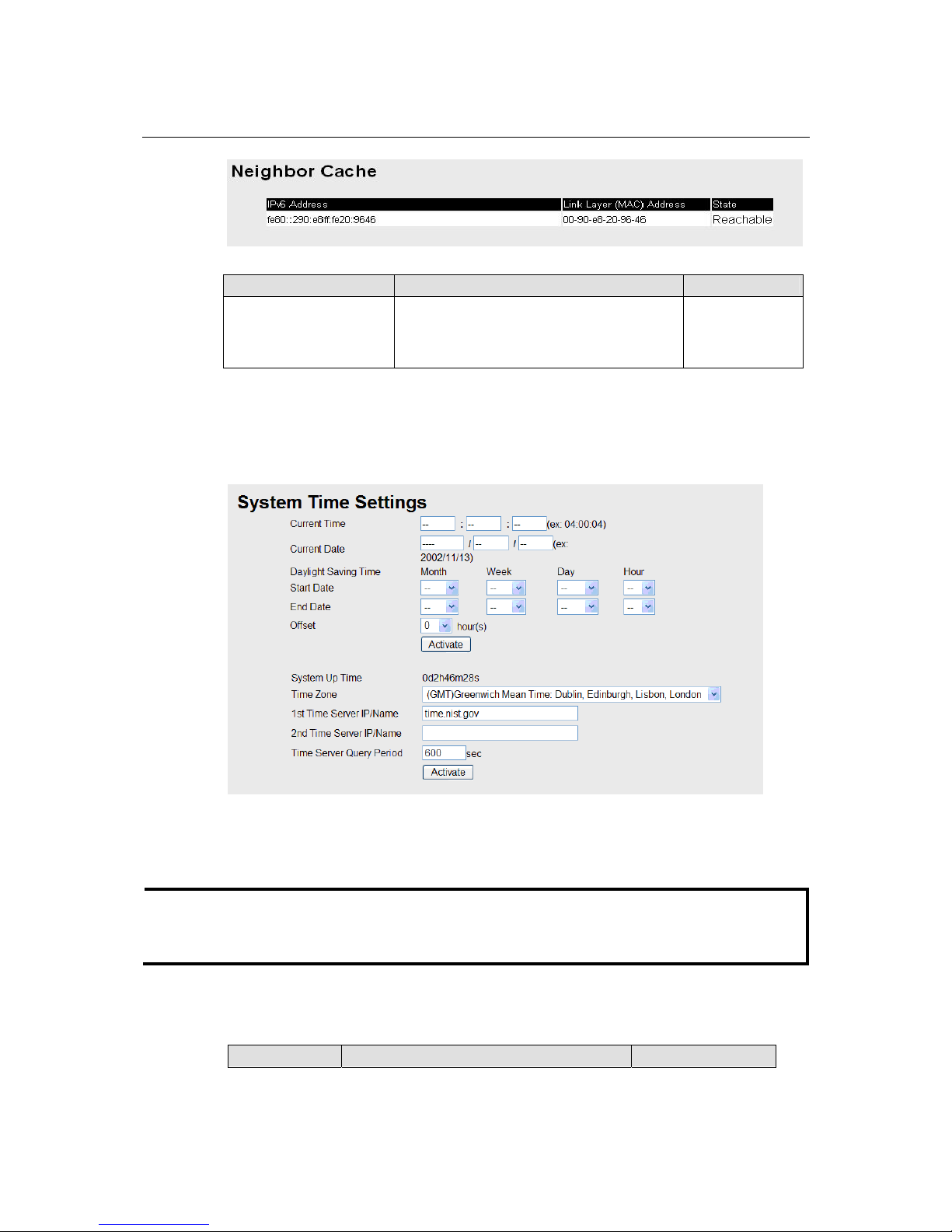
Neighbor Cache
Setting Description Factory Default
None The information in the neighbor cache that
includes the neighboring node’s IPv6 address,
the corresponding Link-Layer address, and the
current state of the entry.
None
Time
The Time configuration page lets users set the time, date, and other settings. An explanation of each
setting is given below the figure.
The switch has a time calibration function based on information from an NTP server or user
specified Time and Date information. Functions such as Auto warning Email can add real-time
information to the message.
NOTE
The IE-SW-VL08M does not have a real time clock. The user must update the Current Time and
Current Date to set the initial time for the device after each reboot, especially when the network
does not have an Internet connection for NTP server or there is no NTP server on the LAN.
Current Time
Setting Description Factory Default

IE-SW-VL08M Series User’s Manual Featured Functions
3-9
User adjustable
time.
The time parameter allows configuration of the
local time in local 24-hour format.
None (hh:mm:ss)
Current Date
Setting Description Factory Default
User adjustable
date.
The date parameter allows configuration of the
local date in yyyy/mm/dd format.
None
(yyyy/mm/dd)
Daylight Saving Time
Daylight saving time (also know as DST or summer time) involves advancing clocks (usually 1
hour) during the summer time to provide an extra hour of daylight in the afternoon.
Start Date
Setting Description Factory Default
User adjustable
date.
The Start Date parameter allows users to enter
the date that daylight saving time begins.
None
End Date
Setting Description Factory Default
User adjustable
date.
The End Date parameter allows users to enter
the date that daylight saving time ends.
None
Offset
Setting Description Factory Default
User adjustable
hour.
The offset parameter indicates how m any ho urs
forward the clock should be advanced.
None
System Up Time
Indicates the switch’s up time from the last cold start. The unit is seconds.
Time Zone
Setting Description Factory Default
User selectable
time zone
The time zone setting allows conversion from
GMT (Greenwich Mean Time) to local time.
GMT (Greenwich
Mean Time)
NOTE
Changing the time zone will automatically correct the current time. You should configure the time
zone before setting the time.
Time Server IP/Name
IE-SW-VL08M Series User’s Manual Featured Functions
3-10
Setting Description Factory Default
1st Time Server
IP/Name
IP or Domain address (e.g., 192.168.1.1 o r
time.nist.gov)
2nd Time Server
IP/Name
The device will try to locate the 2nd NTP
Server if the connection to the 1
st
NTP server
failed.
None
Time Server Query Period
Setting Description Factory Default
Query Period
This parameter determines how frequently the
time is updated from the NTP server.
600 seconds
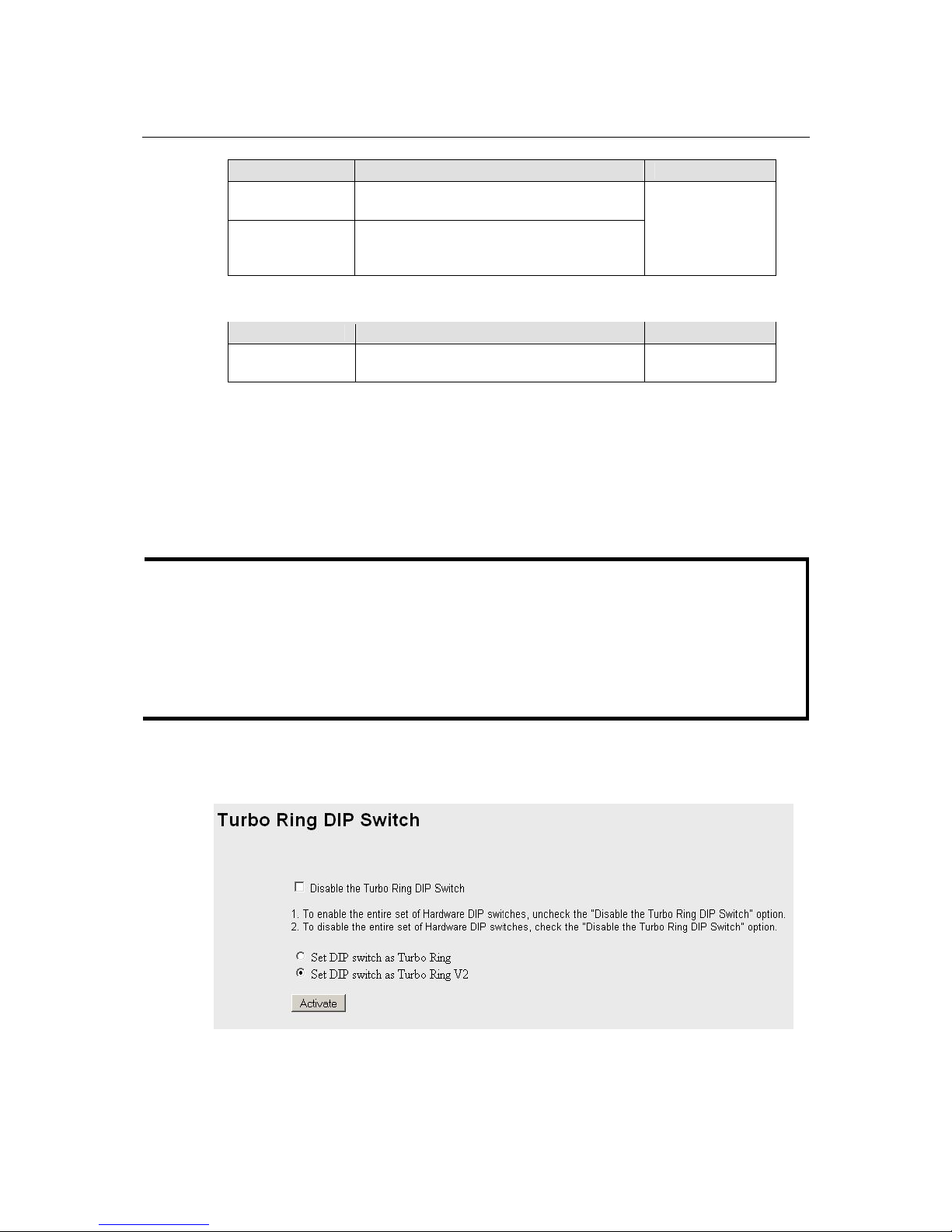
Turbo Ring DIP Switch
The Turbo Ring DIP Switch page allows users to disable the four DIP switches located on the
switch’s outer casing. When enabled, the DIP switches can be used to configure basic settings for
either the “Turbo Ring” protocol or “Turbo Ring V2” protocol. A complete description of the
settings is given below.
NOTE
The “Turbo Ring” protocol (recovery time < 300 ms) provides better network reliability and faster
recovery time for redundant ring topologies. The “Turbo Ring V2” protocol (recovery time < 20
ms), supports additional redundant ring architectures.
In this manual, we use the terminology “Turbo Ring” ring and “Turbo Ring V2” ring to
differentiate between rings configured for one or the other of these protocols.
For a detailed description of “Turbo Ring” and “Turbo Ring V2,” please refer to the Using
Communication Redundancy section later in this chapter.
How to Enable or Disable the Turbo Ring DIP Switches
Enable / Disable the Turbo Ring DIP Switch
IE-SW-VL08M Series User’s Manual Featured Functions
3-11
Setting Description Factory Default
Enable the Turbo
Ring DIP
Switches
The four DIP switches are enabled when the
“Disable the Turbo Ring DIP Switch” box is
not checked.
Disable the Turbo
Ring DIP
Switches
The four DIP switches are disabled when the
“Disable the Turbo Ring DIP Switch” box is
checked.
Not checked (i.e., the Turbo
Ring DIP Switches are
enabled by default)
Set DIP switch as Turbo Ring / Set DIP switch as Turbo Ring V2
Setting Description Factory Default
Set DIP switch as
Turbo Ring
Select this option to enable the Turbo Ring DIP
switches to configure the device for a “Turbo
Ring” ring.
This is the default if you do
NOT reset the switch to
factory default settings
(provided you upgraded the
firmware for Turbo Ring
V2).
Set DIP switch as
Turbo Ring V2
Select this option to enable the Turbo Ring DIP
switches to configure the device for a “Turbo
Ring V2” ring.
This is the default if you DO
reset the switch to factory
default settings (provided
you upgraded the firmware
for Turbo Ring V2).
NOTE
If you upgrade the firmware of your IE- SW-VL08M from Turbo Rin g to Turbo Ring V2, but do not
reset the switch to factory defaults, the DIP switches will be set to configure the device for a “Turbo
Ring” ring. If you reset the switch to factory defaults, the DIP switches will be set to configure the
device for a “Turbo Ring V2” ring.
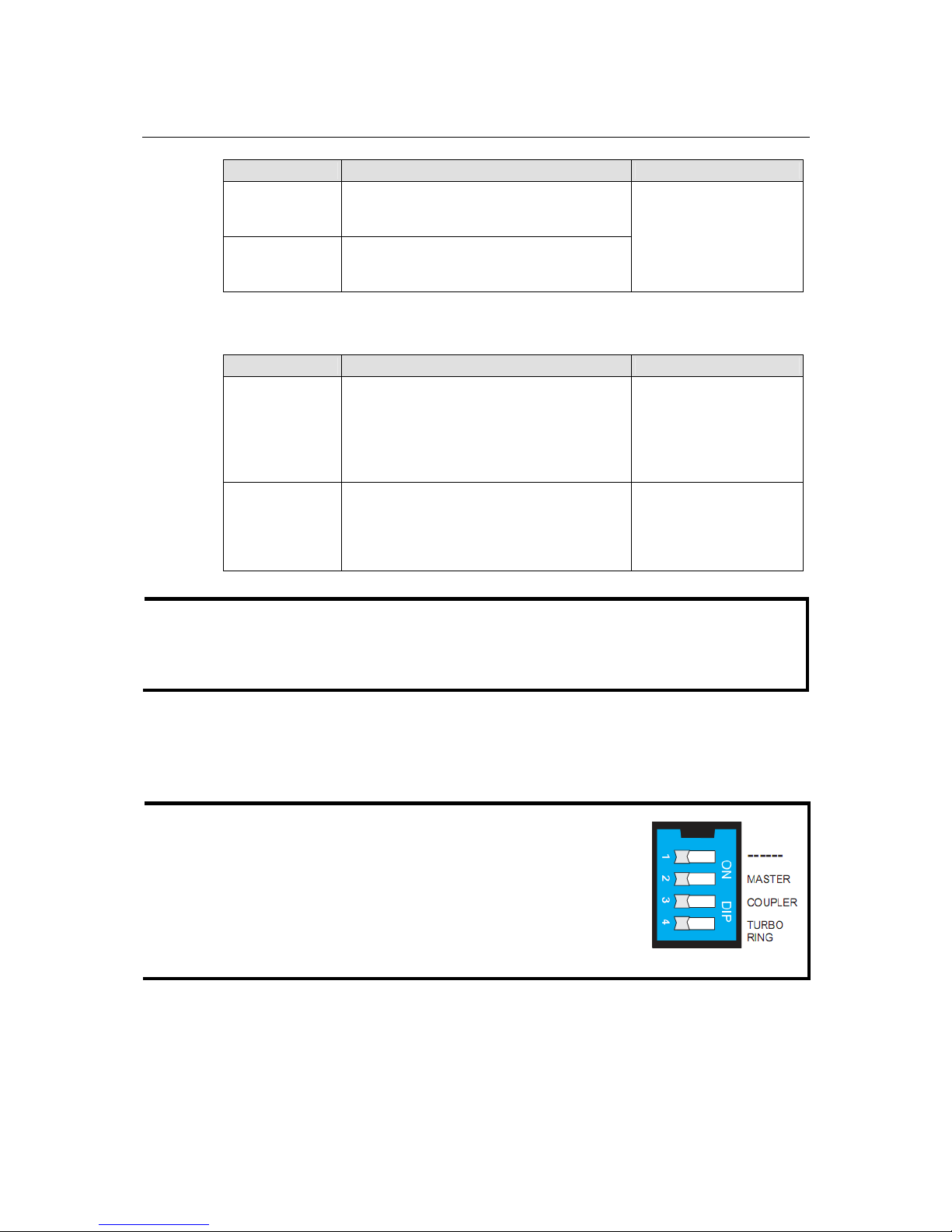
How to Configure the Turbo Ring DIP Switches
The Turbo Ring DIP Switches are set to the OFF position at the factory.
NOTE
The four DIP Switches are used to configure both the “Turbo Ring”
and “Turbo Ring V2” protocol s, depending on whic h protocol is acti ve.
To select which protocol the switch will use, start the user interface
software, and then use the left menu to navigate to the
Communication Redundancy page. To use one of the Turbo Ring
protocols for the switch, select either “Turbo Ring” or “Turbo Ring
V2” in the Redundancy Protocol drop-down box. See the
Configuring “Turbo Ring” and “Turbo Ring V2” section in this
chapter for details.
The following tables show how to use the DIP switches to configure the s witch for “Tu rbo R ing” or
“Turbo Ring V2.”

IE-SW-VL08M Series User’s Manual Featured Functions
3-12
NOTE
DIP switch 4 must be set to the ON position to enable DIP switches 1, 2, and 3. If DIP switch 4 is
set to the “OFF” position, then DIP switches 1, 2, and 3 will all be disabled.
“T urbo Ring” DIP Switch Settings
DIP 1 DIP 2 DIP 3 DIP 4
ON: Enables this
switch as the Ring
Master.
ON
: Enables the
default “Ring
Coupling” ports.
ON
: Activates DIP
switches 1, 2, 3 to
configure “Turbo
Ring” settings.
Reserved for future
use.
OFF
: This switch will
not be the Ring Master.
OFF
: Do not use this
switch as the ring
coupler.
OFF
: DIP switches 1,
2, 3 will be disabled.
“T urbo Ring V2” DIP Switch Settings
DIP 1 DIP 2 DIP 3 DIP 4
ON: Enables the
default “Ring Coupling
(backup)” port.
ON
: Enables this
switch as the Ring
Master.
ON
: Enables the
default “Ring
Coupling” port.
ON
: Activates DIP
switches 1, 2, 3 to
configure “Turbo Ring
V2” settings.
OFF: Enables the
default “Ring Coupling
(primary)” port.
OFF
: This switch will
not be the Ring Master.
OFF
: Do not use this
switch as a ring
coupler.
OFF
: DIP switches 1,
2, 3 will be disabled.
NOTE
The DIP 1 setting will only be active if DIP 3 is in the ON position. If you set DIP 3 to OFF, then
the default Ring Coupling port will NOT be enabled, even if DIP 1 is ON.
Protocol Default Turbo Ring Ports Default Ring Coupling Port(s)
Tur bo Ring
P
orts 4 and 5
P
orts 7 and 8
P
orts 2 and 3
P
orts 5 and 6
Tur bo Ring V2
P
orts 4 and 5
P
orts 7 and 8
P
ort 2
P
ort 5
NOTE
The Turbo Ring Ports and Coupling Ports will be added automatically to all VLANs if you set DIP
Switch 4 to the “ON” position.
NOTE
If you do not enable any of the IE-SW-VL08M switches to be the Ring Master, the Turbo Ring
protocol will automatically choose the IE-SW-VL08M with the smallest MAC address range to be

IE-SW-VL08M Series User’s Manual Featured Functions
3-13
the Ring Master. If you accidentally enable more than one IE-SW-VL08M to be the Ring Master,
these IE-SW-VL08M switches will auto-negotiate to determine which one will be the Ring Master.
NOTE
If you use the browser interface to enable the DIP switches (by un-checking the “Disable the Turbo
Ring DIP switch” checkbox), and then flip DIP switch 4 from ON to OFF, the Ring Ports and
Coupling Ports that were added to all VLANs will be restored to their previous software settings.
(For details, please refer to the “Using Virtual LANs” section of this manual).
System File Update: By Remote TFTP
The IE-SW-VL08M supports saving your configuration file to a remote TFTP server or local host to
allow other IE-SW-VL08M s witches t o use t he same confi guratio n at a l ater tim e, or savi ng the Log
file for future reference. Loading pre-saved firm ware or a configuration file from the TFTP server or
local host is also supported for easy upgrading or configuration of the device.
TFTP Server IP/Name
Setting Description Factory Default
IP Address of the
TFTP Server
The IP or name of the remote TFTP server.
Must be set up before downloading or
uploading files.
None
Configuration Files Path and Name
Setting Description Factory Default
Max. 40
Characters
The path and file name of the device’s
configuration file on the TFTP server.
None
Firmware Files Path and Name
Setting Description Factory Default
Max. 40
Characters
The path and file name of the devices’s
firmware file.
None
Log Files Path and Name
Setting Description Factory Default

IE-SW-VL08M Series User’s Manual Featured Functions
3-14
Max. 40
Characters
The path and file name of the devices’s log
file
None
After setting up the desired path and file name, click Activate to save the setting, and then click
Download to download the prepared file from the remote TFTP server, or click Upload to upload
the desired file to the remote TFTP server.
System File Update: By Local Import/Export
Configuration File
To export the configuration file of this switch, click Export to save it to the local host.
Log File
To export the Log file of this switch, click Export and save it to the local host.
NOTE
Some operating systems will open the configuration file and log file directly in the web page. In
such cases, right click the “Export” button to save a file.
Upgrade Firmware
To import the firmware file of the device, click Browse to select the firmware file already saved on
your computer. The upgrade procedure will proceed automatically after you click Import.
Upload Configuration Data
To import the configuration file of the device, click Browse to select the configuration file already
saved on your computer. The upgrade procedure will proceed automatically after you click Import.
 Loading...