

Weidmuller IE-SW-VL08-8GT, IE-SW-VL08-6GT-2GS Hardware Installation Manual

Gigabit Ethernet Switch – Value Line
IE-SW-VL08-GT Series
Hardware Installation Guide
Third Edition, October 2012
1243390000/02/10.12
Please note:
This document and any further product information - if
available - can be downloaded at the internet link:
http://www.weidmueller.com/downloads
Copyright Notice
Copyright 2012 Weidmüller Interface GmbH & Co. KG
All rights reserved.
Reproduction without permission is prohibited.

- 2 -
Overview
The IE-SW-VL08-GT series is equipped with 8 Gigabit Ethernet ports and up to
2 fiber optic ports, making it ideal for applications that demand high bandwidth.
These Switch Models provide an economical solution for your industrial Gigabit
Ethernet connection, and the built-in relay warning function alerts maintainers
when power failures or port breaks occur. The switches have passed a 100%
burn-in test to ensure that they fulfill the special needs of industrial automation
control. The IE-SW-VL08-GT series can be easily installed with DIN-Rail
mounting as well as distribution boxes.
Package Checklist
Your Ethernet Switch is shipped with the following items. If any of these items
is missing or damaged, please contact your Weidmüller customer service for
assistance.
Ethernet Switch
Hardware Installation Guide
Protective caps for unused ports
Features
High Performance Network Switching Technology
10/100/1000BaseT(X) (RJ45), auto negotiation speed, F/H duplex mode,
and auto MDI/MDI-X connection, 100/1000 BaseSFP slot.
IEEE 802.3/802.3u/802.3ab/802.3z/802.3x.
Store and Forward switching process type, 8K MAC address entries.
Industrial Grade Reliablity
Power failure, port break alarm by relay output
Redundant dual AC/DC power inputs
Rugged Design
Operating temperature range of 0 to 60°C or -40 to 75°C for -T models
IP30, rugged high-strength case
DIN-Rail or panel mounting ability
Redundant dual 12/24/48VDC or 18 to 30 VAC at 47 to 63Hz Power inputs
- 3 -
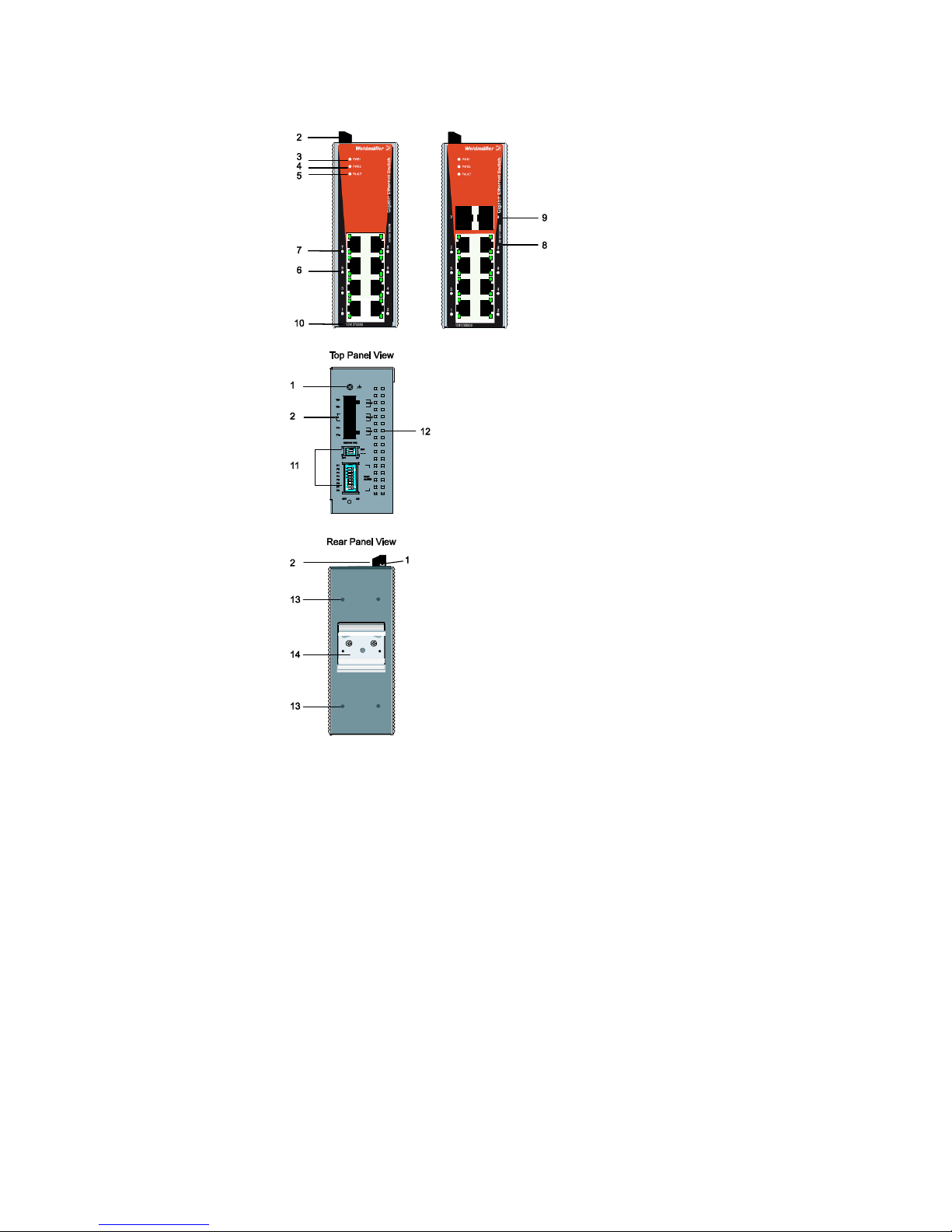
Panel Layout of
IE-SW-VL08-GT Series
1. Grounding screw
2. Terminal block for power input
(PWR1, PWR2) and relay output
3. Power input PWR1 LED
4. Power input PWR2 LED
5. Fault LED
6. TP port’s 10/10/1000 Mbps LED
7. Port number
8. 10/100/1000BaseT(X) Port
9. 100/1000Base SFP slot
10. Article Number
11. DIP switches
12. Heat dissipation orifices
13. Screw hole for wall mounting kit
14. DIN-Rail Kit
IE-SW-VL08-8GT
Front Panel View
IE-SW-VL08-6GT-2GS
Front Panel View
- 4 -
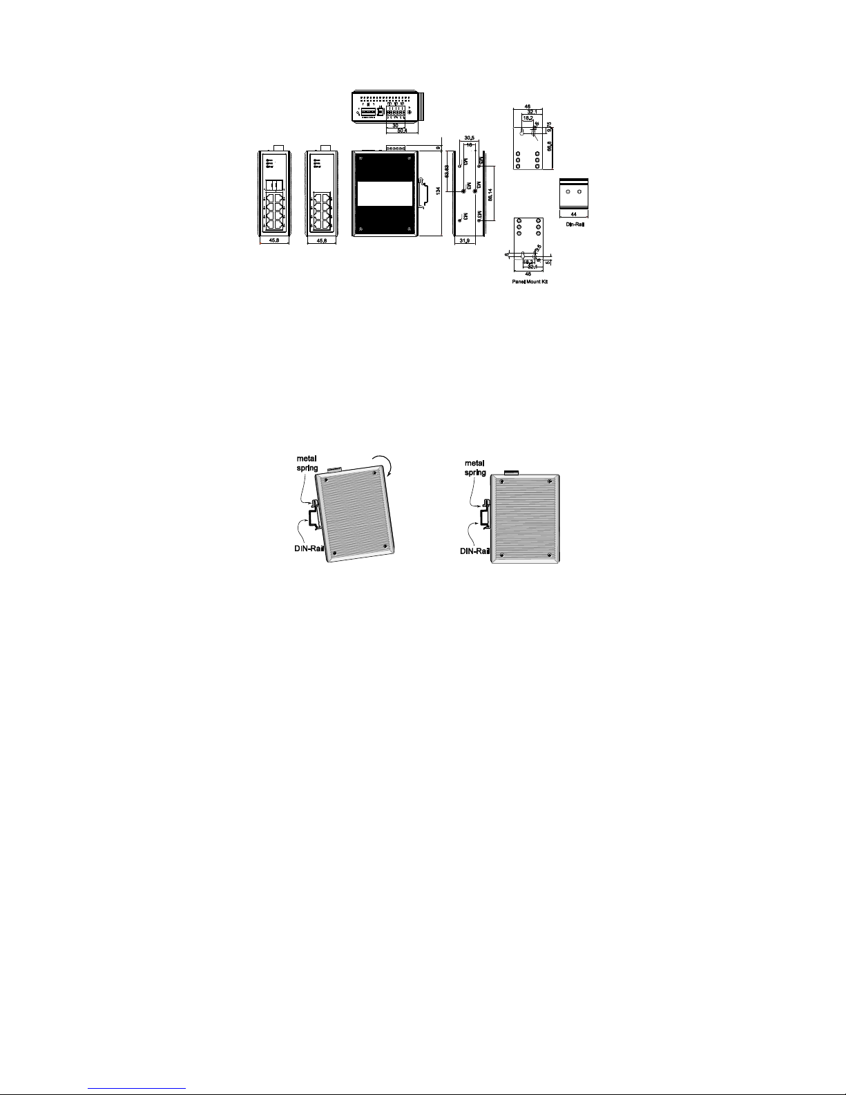
Mounting Dimensions (unit = mm)
DIN-Rail Mounting
The aluminum DIN-rail attachment plate should already be fixed to the back
panel of the Ethernet Switch when you take it out of the box. If you need to
reattach the DIN-rail attachment plate, make sure the stiff metal spring is
situated towards the top, as shown in the figures below.
STEP 1:
Insert the top of the DIN-rail into the
slot just below the stiff metal spring.
STEP 2:
The DIN-rail attachment unit will
snap into place as shown below.
To remove the DIN-rail from the Ethernet Switch, simply reverse Steps 1 and 2.
- 5 -
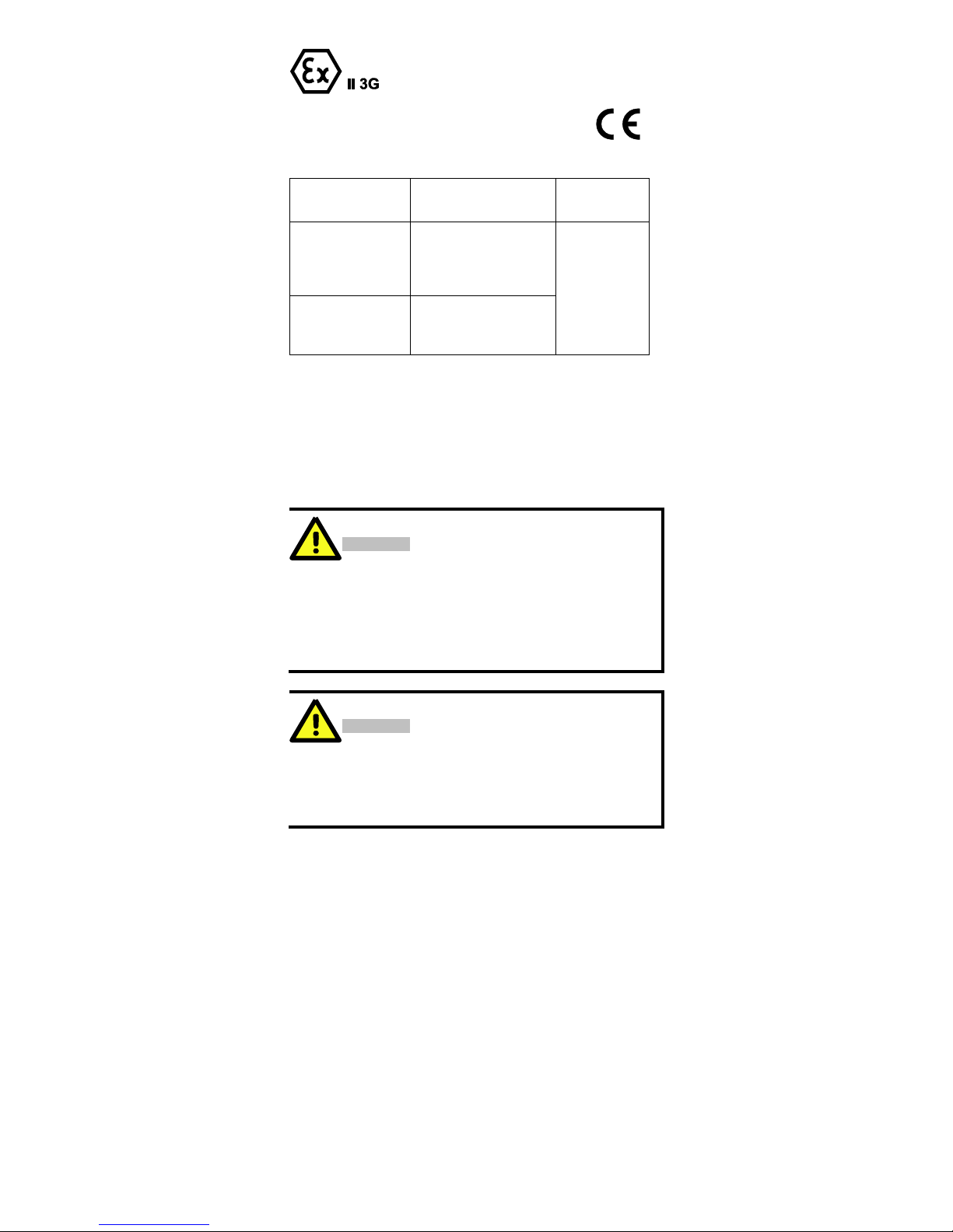
ATEX Information
1. Certificate number DEMKO 11 ATEX 150194X
2. Ambient range (-40°C ≤ Tamb ≤ 75°C)
3. Certification string (Ex nC nL IIC T4)
4. Standards covered ( EN60079-0:2006, EN60079-15:2005)
5. Electric data
Model No.
Rated Supply Voltage and
Current
Relay Contact
Rating
IE-SW-VL08-8GT
12-48 V DC, Class 2,
Maximum 0.65 A;
18-30 V AC, Class 2, 50/60
Hz, Maximum 0.5 A
24 V DC, 1 A,
resistive load
IE-SW-VL08-8GT-2GS
12-48 V DC, Class 2,
Maximum 0.71 A;
18-30 V AC, Class 2, 50/60
Hz, Maximum 0.55 A
6. The conditions of safe usage:
These products must be mounted in an IP54 enclosure.
Install in an area of pollution degree 2 or less.
Use power supply terminal conductors suitable for use in an ambient
temperature of 90°C
For ambient temperatures below –10°C and above +60°C use field wiring
suitable for both minimum and maximum ambient temperatures.
Wiring Requirements
WARNING
Safety First!
Turn the power off before disconnecting modules or wires. The
proper power supply voltage is listed on the product label. Check
the voltage of your power source to make sure you are using the
correct voltage. Do NOT use a voltage greater than what is
specified on the product label.
These devices must be supplied by an AELV source as defined in
the Low Voltage Directive 2006/95/EC and 2004/108/EC.
WARNING
Safety First!
Calculate the maximum possible current in each power wire and
common wire. Observe all electrical codes dictating the maximum
current allowable for each wire size.
If the current goes above the maximum ratings, the wiring could
overheat, causing serious damage to your equipment.
 Loading...