

Weidmuller IE-SW-PL18M-2GC-16TX, IE-SW-PL18M, IE-SW-PL18M-2GC-14TX2SC, IE-SW-PL18M-2GC-14TX2ST, IE-SW-PL18M-2GC-14TX2SCS Hardware Installation Manual

Ethernet Switch – Premium Line
IE-SW-PL18M Series (Managed)
Hardware Installation Guide
Fourth Edition, October 2012
1243410000/03/10.12
Please note:
This document, the detailed manual and any further
product information - if available - can be
downloaded at the internet link:
http://www.weidmueller.com/downloads
Copyright Notice
Copyright 2012 Weidmüller Interface GmbH & Co. KG
All rights reserved.
Reproduction without permission is prohibited.

- 2 -
Package Checklist
Your Ethernet Switch is shipped with the following items. If any of these
items are missing or damaged, please contact your Weidmüller customer
service for assistance.
1 Ethernet Switch IE-SW-PL18M
Hardware Installation Guide
CD-ROM with User’s Manual and Windows Utility (option)
Please download CD-ROM from Internet page
http://www.weidmueller.com/downloads
RJ45 to DB9 Console port cable
Protective caps for unused ports
Optional Accessories
SFP-Transceiver (Fast Ethernet and Gigabit Ethernet modules for different
transmission lengths)
RM-KIT (19” rack mounting kit)
More detailed information in datasheet
- 3 -
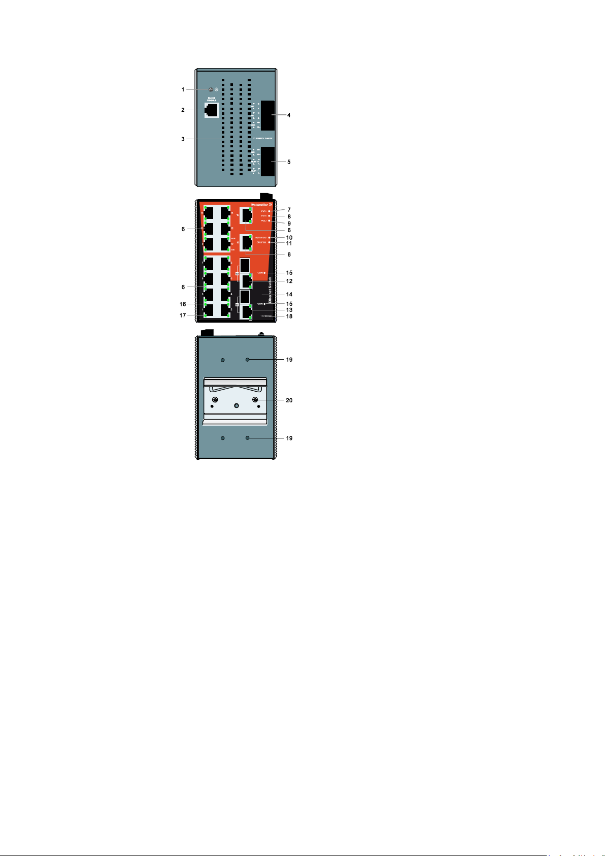
Panel Views of
1. Grounding screw
2. Console port
3. Heat dissipation orifices
4. 6-pin terminal block for DI 1, DI
2, and PWR 2
5. 6-pin terminal block for PWR1
Relay 1, and Relay 2
6. 10/100BaseT(X), ports 1 to 16
7. PWR 1: LED for power input 1
8. PWR 2: LED for power input 2
9. Fault LED
10. MSTR/HEAD LED
11. CPLR/TAIL LED
12. 10/100/1000BaseT(X), port G2
13. 10/100/1000BaseT(X), port G1
14. Label
15. 1000 Mbps LEDs
16. TP port’s 100 Mbps LED
17. TP port’s 10 Mbps LED
18. Article Number
19. Screw hole for Wall Mounting
Kit
20. DIN-Rail Kit
IE-SW-PL18M-2GC-16TX
- 4 -
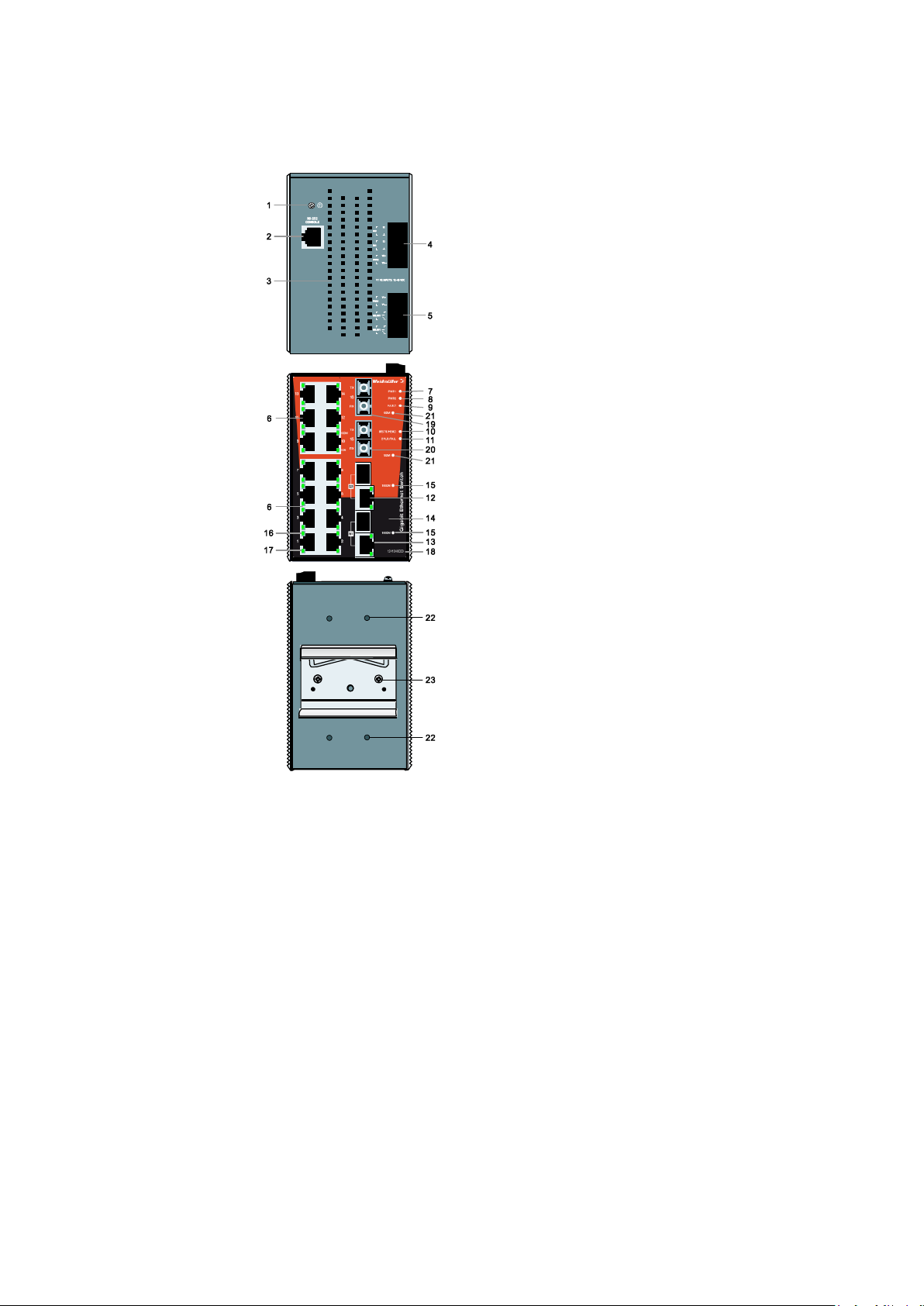
Panel Views of models
NOTE:
The appearance of models
IE-SW-PL18M-2GC14TX2SCS,
IE-SW-PL18M-2GC14TX2SC and
IE-SW-PL18M-2GC14TX2ST are apart from the optical connectors identical.
1. Grounding screw
2. Console port
3. Heat dissipation orifices
4. 6-pin terminal block for DI 1, DI 2,
and PWR 2
5. 6-pin terminal block for PWR1
Relay 1, and Relay 2
6. 10/100BaseT(X), ports 1 to 14
7. PWR 1: LED for power input 1
8. PWR 2: LED for power input 2
9. Fault LED
10. MSTR/HEAD LED
11. CPLR/TAIL LED
12. 10/100/1000BaseT(X) Port G2
13. 10/100/1000BaseT(X) Port G1
14. Label
15. 1000 Mbps LEDs
16. TP port’s 100 Mbps LED
17. TP port’s 10 Mbps LED
18. Article Number
19. 100BaseFX Port 16
20. 100BaseFX Port 15
21. 100BaseFX LEDs
22. Screw hole for Wall Mounting Kit
23. DIN-Rail Kit
IE-SW-PL18M-2GC-14TX2ST
IE-SW-PL18M-2GC-14TX2SC
IE-SW-PL18M-2GC-14TX2SCS
- 5 -
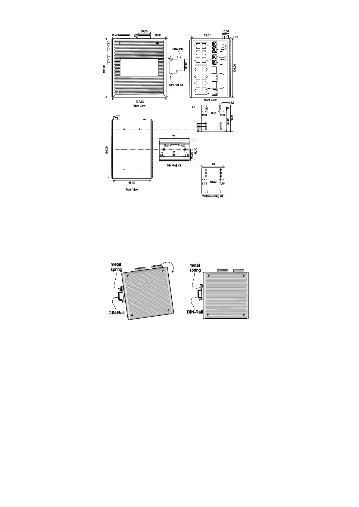
Mounting Dimensions (unit = mm)
STEP 1—Insert the top of the
DIN-Rail into the slot just below the
stiff metal spring.
STEP 2—The DIN-Rail attachment
unit will snap into place as shown in
the following illustration.
DIN-Rail Mounting
The aluminum DIN-Rail attachment plate should already be fixed to the back
panel of IE-SW-PL18M when you take it out of the box. If you need to
reattach the DIN-Rail attachment plate to IE-SW-PL18M, make sure the stiff
metal spring is situated towards the top, as shown by the following figures.
To remove the IE-SW-PL18M from the DIN-Rail, simply reverse Steps 1 and
2 above.
 Loading...