

Weidmuller IE-SW-PL06M-2TX-4PoE Hardware Installation Manual

Ethernet PoE Switch - Premium Line
IE-SW-PL06M-2TX-4PoE (Managed)
Hardware Installation Guide
Second Edition, October 2012
1254050000/01/10.12
Please note:
This document, the detailed manual and any further
product information - if available - can be
downloaded at the internet link:
http://www.weidmueller.com/downloads
Copyright Notice
Copyright 2012 Weidmüller Interface GmbH & Co. KG
All rights reserved.
Reproduction without permission is prohibited.

- 2 -
Overview
The IE-SW-PL06M-2TX-4PoE is a managed redundant Ethernet switch that
comes standard with 4 10/100BaseT(X) 802.3at/af (PoE/PoE+) compliant
Ethernet ports and 2 10/100BaseT(X) Ethernet ports. The PoE Switch
provides up to 30 watts of power per PoE port, and allow power to be
supplied to connected devices (such as surveillance cameras, wireless access
points, and IP phones) when power is not readily available or cost-prohibitive
to provide locally. The Ethernet switch supports a variety of management
functions, including Turbo Chain, IEEE 1588 PTP, Turbo Ring, RSTP/STP,
IGMP, VLAN, QoS, RMON, bandwidth management, and port mirroring.
This PoE Switch is designed especially for security automation applications
such as IP surveillance and gate of entry systems, which can benefit from a
scalable backbone construction and Power-over-Ethernet support.
The switch can operate from 0 to 60°C and the rugged hardware design
makes it perfect for ensuring that your Ethernet equipment can operate in
critical industrial environments, and complies with FCC and CE standards.
Package Checklist
IE-SW-PLM-PoE-Switches are shipped with the following items. If any of
these items are missing or damaged, please contact your customer service
representative for assistance.
1 Ethernet Switch IE-SW-PL06M-2TX-4PoE
Hardware Installation Guide (this guide)
CD-ROM with User’s Manual and Windows Utility (option)
Please download CD-ROM from Internet page
http://www.weidmueller.com/downloads
RJ45 to DB9 console port cable
Protective caps for unused ports
- 3 -
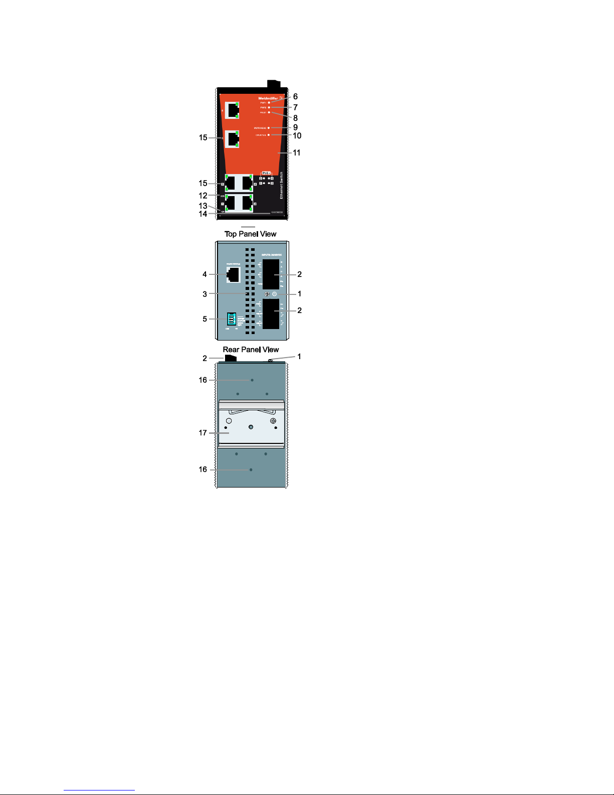
Panel Layout of
IE-SW-PL06M-2TX-4PoE
1. Grounding screw
2. Terminal block for power input
PWR1/PWR2 and relay output
3. Heat dissipation orifices
4. Console port
5. DIP switches
6. Power input PWR1 LED
7. Power input PWR2 LED
8. Fault LED
9. MSTR/HEAD LED indicator
10. CPLR/TAIL LED indicator
11. Label
12. TP port’s 100 Mbps LED
13. TP port’s 10 Mbps LED
14. Article Number
15. 10/100 BaseT(X) Ports
16. Screw hole for wall mounting kit
17. DIN-Rail kit
IE-SW-PL06M-2TX-4PoE
Front Panel View
- 4 -
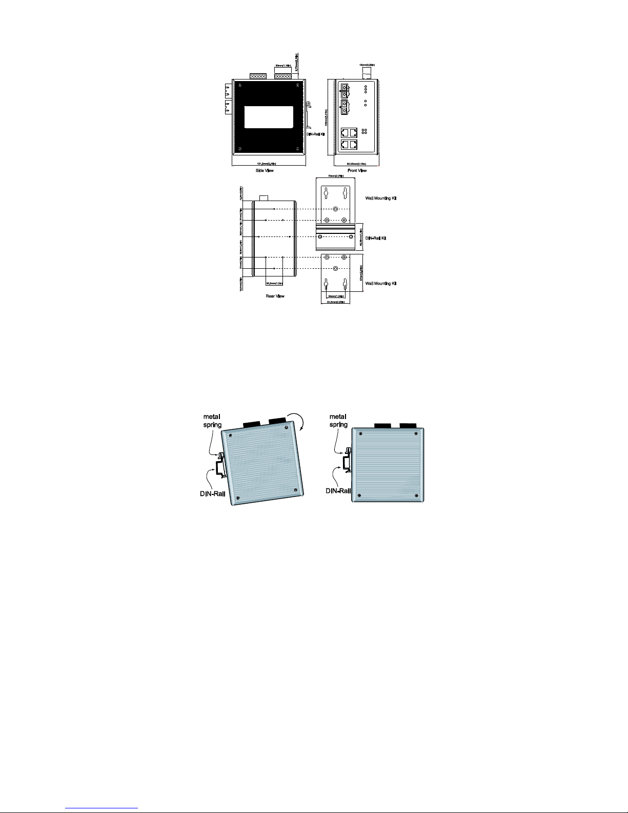
Mounting Dimensions
DIN-Rail Mounting
The aluminum DIN-Rail attachment plate should already be fixed to the back
panel of the IE-SW-PL06M-2TX-4PoE when you take it out of the box. If
you need to reattach the DIN-Rail attachment plate to the switch, make sure
the stiff metal spring is situated towards the top, as shown by the following
figures.
STEP 1—Insert the top of the
DIN-Rail into the slot just below the
stiff metal spring.
STEP 2—The DIN-Rail attachment
unit will snap into place as shown in
the following illustration.
To remove the Ethernet switch from the DIN-Rail, simply reverse Steps 1 and
2 above.
 Loading...