

Weider 831149330 Owner’s Manual
Model No. 831.14933.0
Serial No.
Write the serial number in the space
above for reference.
Decal
• Assembly
• Operation
• Maintenance
• Part List and Drawing
WEIGHT BENCH EXERCISER
User's Manual
Sears, Roebuck and Co.
Hoffman Estates, IL 60179
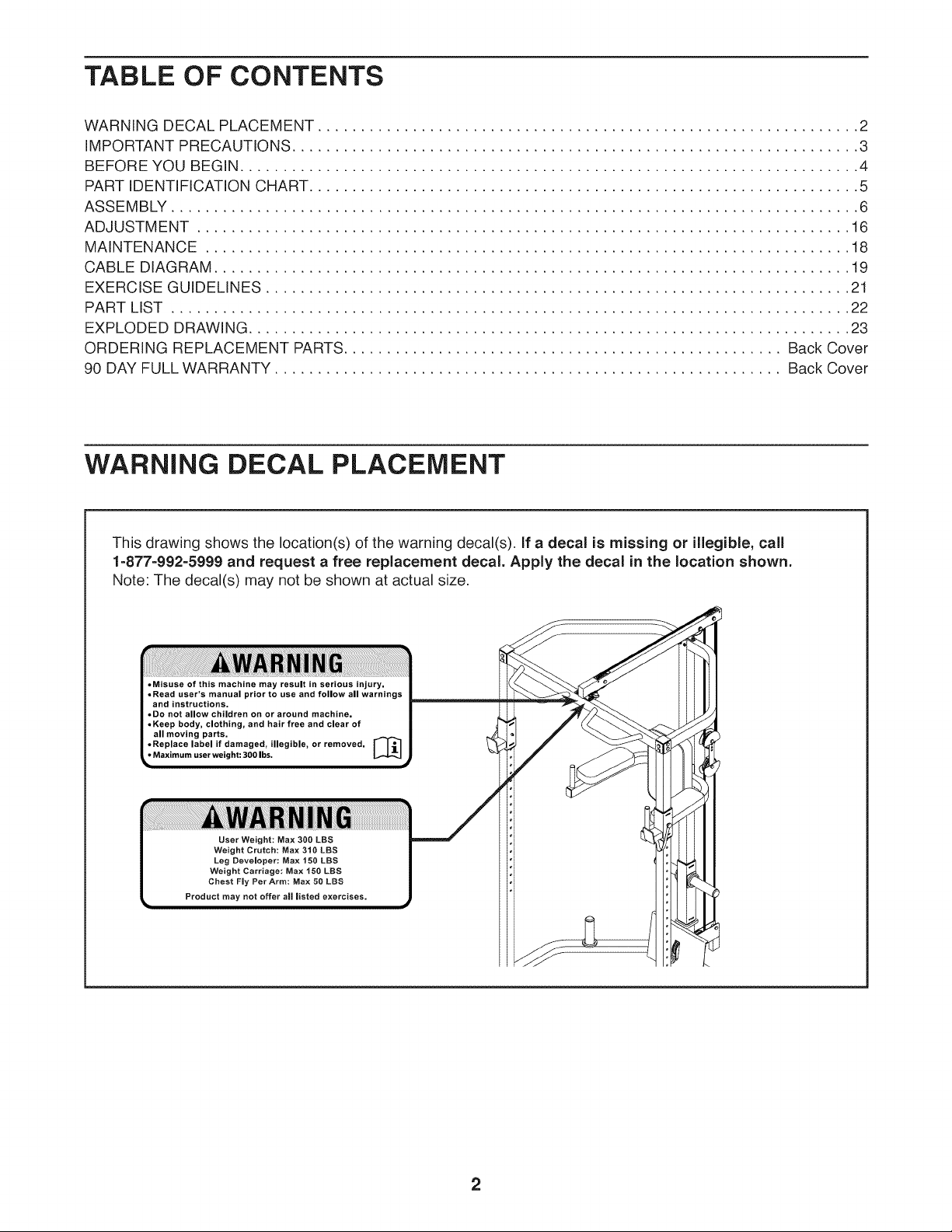
TABLE OF CONTENTS
WARNING DECAL PLACEMENT ............................................................... 2
IMPORTANT PRECAUTIONS .................................................................. 3
BEFORE YOU BEGIN ........................................................................ 4
PART IDENTIFICATION CHART ................................................................ 5
ASSEMBLY ................................................................................ 6
ADJUSTMENT ............................................................................ 16
MAINTENANCE ........................................................................... 18
CABLE DIAGRAM .......................................................................... 19
EXERCISE GUIDELINES .................................................................... 21
PART LIST ............................................................................... 22
EXPLODED DRAWING ...................................................................... 23
ORDERING REPLACEMENT PARTS................................................... Back Cover
90 DAY FULL WARRANTY ........................................................... Back Cover
WARNING DECAL PLACEMENT
This drawing shows the location(s) of the warning decal(s). If a decal is missing or illegible, call
1=877=992=5999 and request a free replacement decal. Apply the decal inthe location shown.
Note: The decal(s) may not be shown at actual size.
• Misuse of this machine may result in serious injury. |
• Read user's manual prior to use and follow all warnings |
and instructions, i
• Do not allow children on or around machine. |
.Keep body, clothing, and hair free and clear of |
allmoving parts. _ I
• Replace label if damaged, illegibl ....... oved. I I_I I
Maximum user weight: 300 Ibs. L,_I_J J
Product may not offer all listed
J
2
iMPORTANT PRECAUTIONS
WARNING: Toreducether skofserious niury,reada, mportantprecautionsand
instructions in this manual and all warnings on your weight bench before using your weight bench.
Sears assumes no responsibility for personal injury or property damage sustained by or through the
use of this product.
1. it is the responsibility of the owner to ensure 9.
that all users of the weight bench are ade-
quately informed of all precautions.
.
Before beginning any exercise program,
consult your physician. This is especially
important for persons over age 35 or per-
sons with pre-existing health problems.
,
Use the weight bench only as described in
this manual.
.
The weight bench is intended for home use
only. Do not use the weight bench in a com-
mercial, rental, or institutional setting.
.
Keep the weight bench indoors, away from
moisture and dust. Do not put the weight
bench in a garage or covered patio, or near
water.
,
Place the weight bench on a level surface,
with a mat beneath it to protect the floor or
carpet. Make sure that there is enough clear-
ance around the weight bench to mount,
dismount, and use it.
.
Inspect and properly tighten all parts regu-
larly. Replace any worn parts immediately.
,
Keep children under age 12 and pets away
from the weight bench at all times.
Wear appropriate clothes while exercising;
do not wear loose clothes that could become
caught on the weight bench. Wear athletic
shoes for foot protection while exercising.
10.
Keep hands and feet away from moving
parts.
11.
The weight bench is designed to support a
maximum user weight of 300 Ibs. (136 kg)
Do not place more than 150 Ibs. (68 kg) of
weight on the weight carriage. Do not place
more than 310 Ibs. (141 kg) of weight, includ-
ing a barbell, on the bar cradles. Note: A
barbell is not included.
12.
Before you use the bar cradles, make sure
that the adjustment pins are fully inserted
through the bar cradles and through the
uprights.
13.
Do not use a barbell that is longer than 6 ft.
(1.8 m) with the weight bench.
14.
Make sure that the cables remain on the pul-
leys at all times. If the cables bind while you
are exercising, stop immediately and make
sure that the cables are on the pulleys.
15.
Over exercising may result in serious injury
or death, if you feel faint or if you experience
pain while exercising, stop immediately and
cool down.
3
BEFORE YOU BEGIN
Thank you for selecting the versatile WELDER PRO TM
weight bench. Whether your goal is to tone your body,
build dramatic muscle size and strength, or improve
your cardiovascular system, the weight bench will help
you to achieve the specific results you want.
For your benefit, read this manual carefully before
using the weight bench. If you have questions after
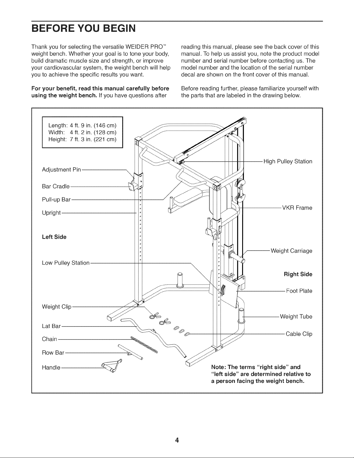
Length 4 ft. 9 in. (146 cm)
Width: 4 ft. 2 in. (128 cm)
Height: 7 ft. 3 in. (221 cm)
Adjustment Pin
Bar Cradle
Pull-up Bar
Upright
reading this manual, please see the back cover of this
manual. To help us assist you, note the product model
number and serial number before contacting us. The
model number and the location of the serial number
decal are shown on the front cover of this manual.
Before reading further, please familiarize yourself with
the parts that are labeled in the drawing below.
gh Pulley Station
v'KR Frame
Left Side
Low Pulley Station
Weight Clip
Lat Bar
Chain
Row Bar
Handle
Weight Carriage
Right Side
Foot Plate
Weight Tube
Cable Clip
Note: The terms "right side" and
"left side" are determined relative to
a person facing the weight bench.
4
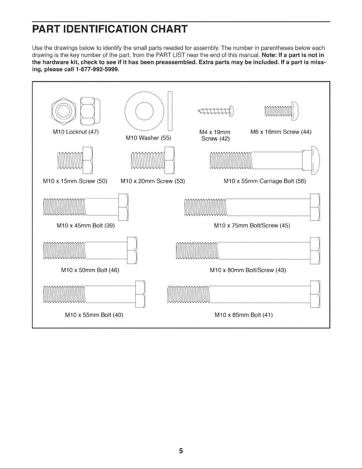
PART iDENTiFiCATiON CHART
Use the drawings below to identify the small parts needed for assembly. The number in parentheses below each
drawing is the key number of the part, from the PART LIST near the end of this manual. Note: If a part is not in
the hardware kit, check to see if it has been preassembled. Extra parts may be included, if a part is miss-
ing, please call 1=877=992=5999.
M10 Locknut (47)
M10 x 15mm Screw (50)
MIO x 45mm Bolt (39)
M10 x 50mm Bolt (46)
M10 Washer (55)
M10 x 20mm Screw (53)
M4 x 19mm
Screw (42)
M10 x 55mm Carriage Bolt (56)
M10 x 75mm Bolt/Screw (45)
M10 x 80mm Bolt/Screw (43)
M6 x 16mm Screw (44)
M10 x 55mm Bolt (40)
MIO x 85mm Bolt (41)
5
ASSEMBLY
Assembly requires two persons.
Due to its weight and size, the weight bench
should be assembled in the location where it will
be used. Make sure that there is enough clear-
ance to walk around the weight bench as you
assemble it.
Place all parts in a cleared area and remove the
packing materials. Do not dispose of the packing
materials until you finish all assembly steps.
Left parts are marked "L" or "Left" and right parts
are marked "R" or "Right."
The Three Stages of the Assembly Process
Frame Assembly--You will begin by assembling
the bases and the uprights that form the skeleton of
the weight bench.
Cable Assembly--During this stage you will attach
To identify small parts, see page 5.
in addition to the included tool(s), assembly
requires the following tool(s):
two adjustable wrenches
one Phillips screwdriver
Assembly may be easier if you have a set of
wrenches. To avoid damaging parts, do not use
power tools.
the cables and pulleys that connect the weight
carriage to the frame.
VKR Assembly--During this stage you will
assemble the VKR frame and pads.
.
Go to www.weiderservice.com/registration on
your computer and register your product.
• activates your warranty
• saves you time if you ever need to contact
Customer Care
• allows us to notify you of upgrades and offers
Note: if you do not have Internet access, call
1-877-992-5999 and register your product.
6

,
Orient the Right and Left Bases (1, 2) as shown.
Insert the Right Base into the Left Base.
Attach the Guide (4) to the Right and Left Bases
(1,2) with two M10 x 55mm Carriage Bolts (56)
and two M10 Locknuts (47). Do not fully tighten
the Locknuts yet.
,
Attach the Foot Plate (11) to the Guide (4) with
an M10 x 75mm Screw (45), an M10 Washer
(55), two M10 x 85mm Bolts (41), and two
M10 Locknuts (47). Do not fully tighten the
Locknuts yet.
56
45
41
47
7
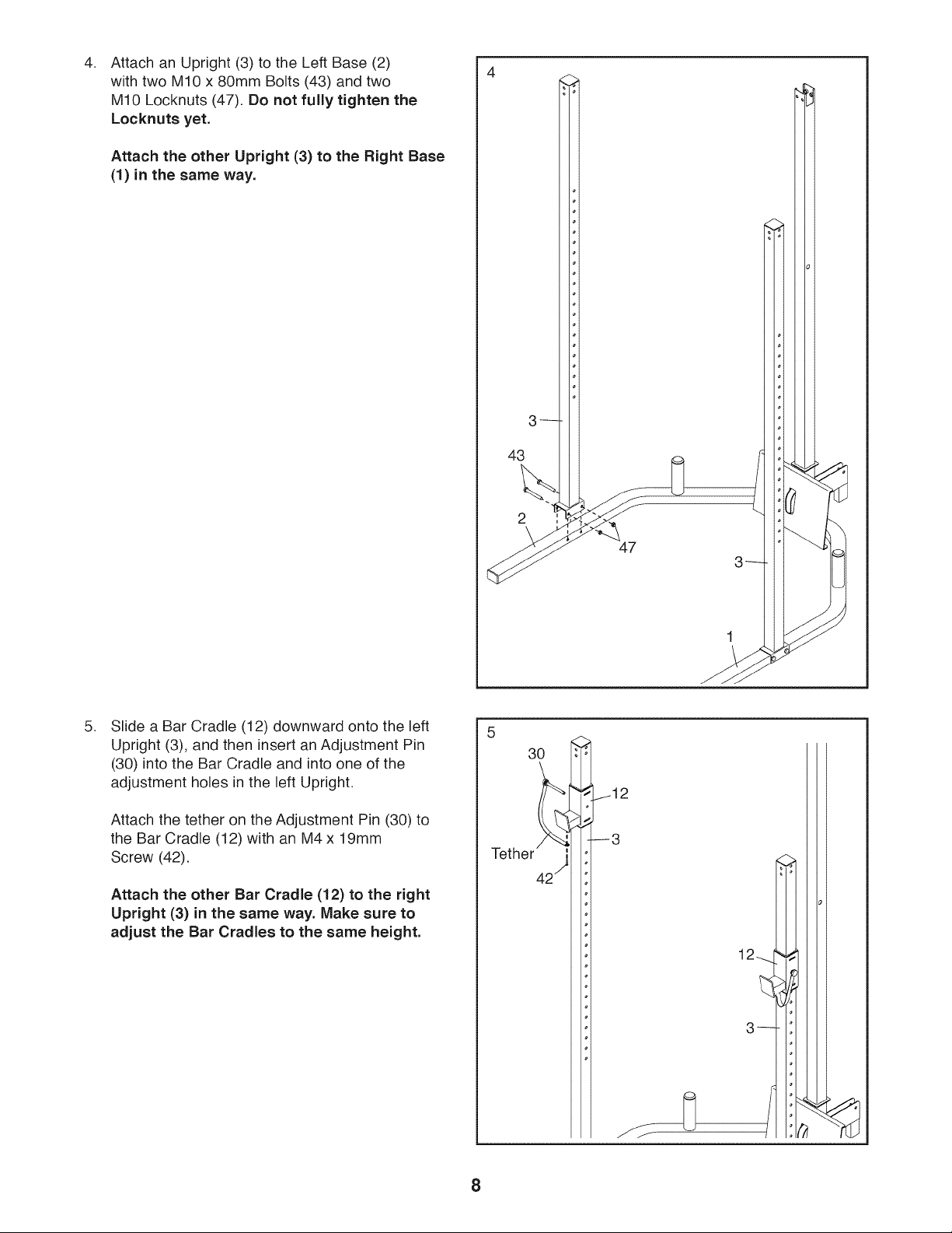
Attach an Upright (3) to the Left Base (2)
4. 4
with two M10 x 80mm Bolts (43) and two
M10 Locknuts (47). Do not fully tighten the
Locknuts yet.
Attach the other Upright (3) to the Right Base
(1) in the same way.
3_
43
,
Slide a Bar Cradle (12) downward onto the left
Upright (3), and then insert an Adjustment Pin
(30) into the Bar Cradle and into one of the
adjustment holes in the left Upright.
Attach the tether on the Adjustment Pin (30) to
the Bar Cradle (12)with an M4 x 19mm
Screw (42).
Attach the other Bar Cradle (12) to the right
Upright (3) in the same way. Make sure to
adjust the Bar Cradles to the same height.
47
3--
30
8
 Loading...