

Weider 831149222 Owner’s Manual

Model No. 831.14922.2
Serial No.
|
Write the serial number in the space
above for reference.
Serial Number Decal
(under the seat)
• Assembly
• Operation
• Maintenance
• Part List and Drawing
WEIGHT SYSTEM EXERCISER
User's Manual
Sears, Roebuck and Co.
Hoffman Estates, IL 60179
i_w _w_ FREE
(_ HOW-TO "_
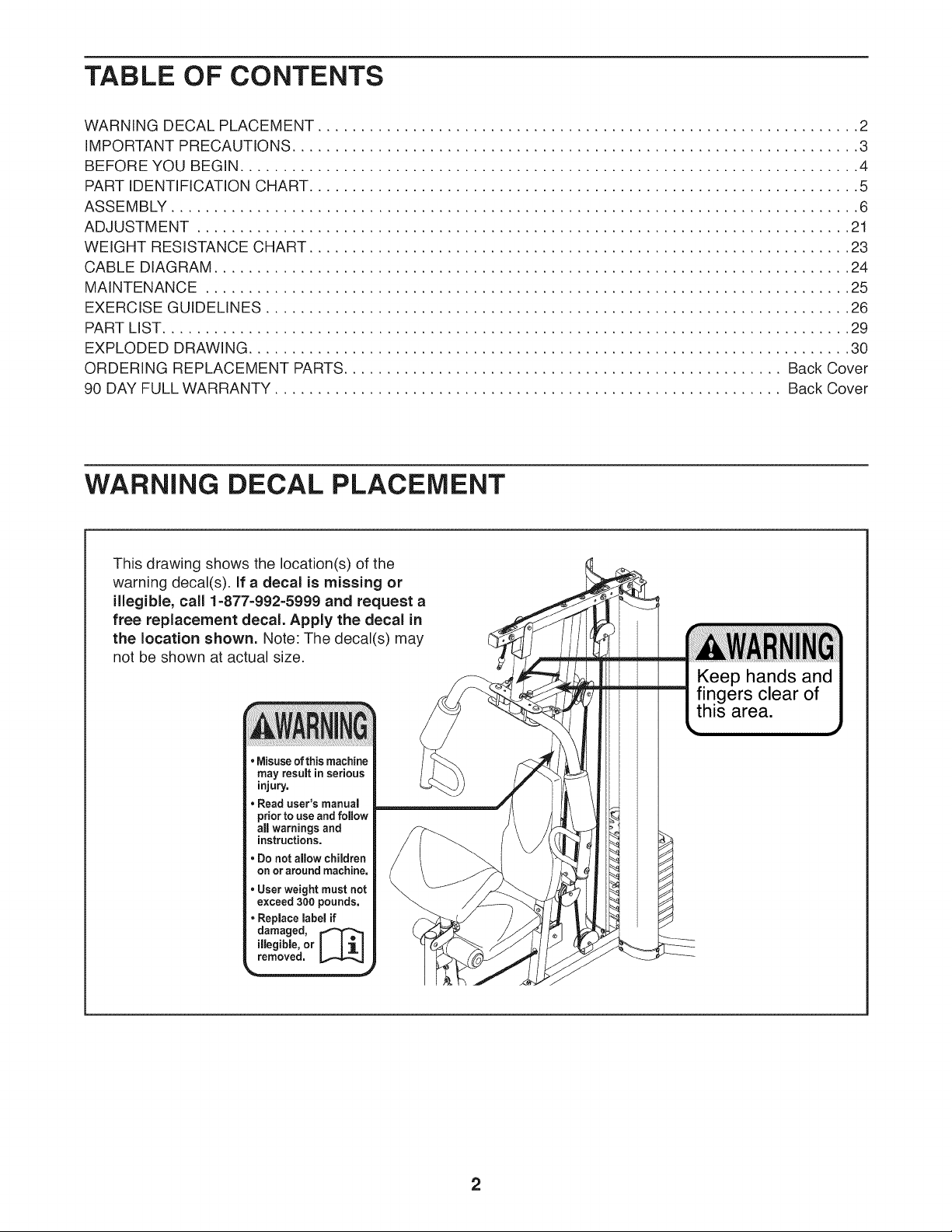
TABLE OF CONTENTS
WARNING DECAL PLACEMENT ............................................................... 2
IMPORTANT PRECAUTIONS .................................................................. 3
BEFORE YOU BEGIN ........................................................................ 4
PART IDENTIFICATION CHART ................................................................ 5
ASSEMBLY ................................................................................ 6
ADJUSTMENT ............................................................................ 21
WEIGHT RESISTANCE CHART ............................................................... 23
CABLE DIAGRAM .......................................................................... 24
MAINTENANCE ........................................................................... 25
EXERCISE GUIDELINES .................................................................... 26
PART LIST................................................................................ 29
EXPLODED DRAWING ...................................................................... 30
ORDERING REPLACEMENT PARTS ................................................... Back Cover
90 DAY FULL WARRANTY ........................................................... Back Cover
WARNING DECAL PLACEMENT
This drawing shows the location(s) of the
warning decal(s). If a decal is missing or
illegible, call 1-877-992=5999 and request a
free replacement decal. Apply the decal in
the location shown. Note: The decal(s) may
not be shown at actual size.
• Misuseof this machine
may result in serious
injury.
• Read user's manual
prior to use and follow
all warnings and
instructions.
• Do not aflow children
on or around machine,
• User weight must not
exceed300 pounds,
• Replace label if
illegible, or
damaged, [_
removed,
2
iMPORTANT PRECAUTIONS
3
BEFORE YOU BEGIN
Thank you for selecting the versatile WELDER PRO"R_
6900 weight system. The weight system offers a selec-
tion of weight stations designed to develop every major
muscle group of the body. Whether your goal is to tone
your body, build dramatic muscle size and strength, or
improve your cardiovascular system, the weight system
will help you to achieve the specific results you want.
For your benefit, read this manual carefully before
using the weight system. If you have questions after
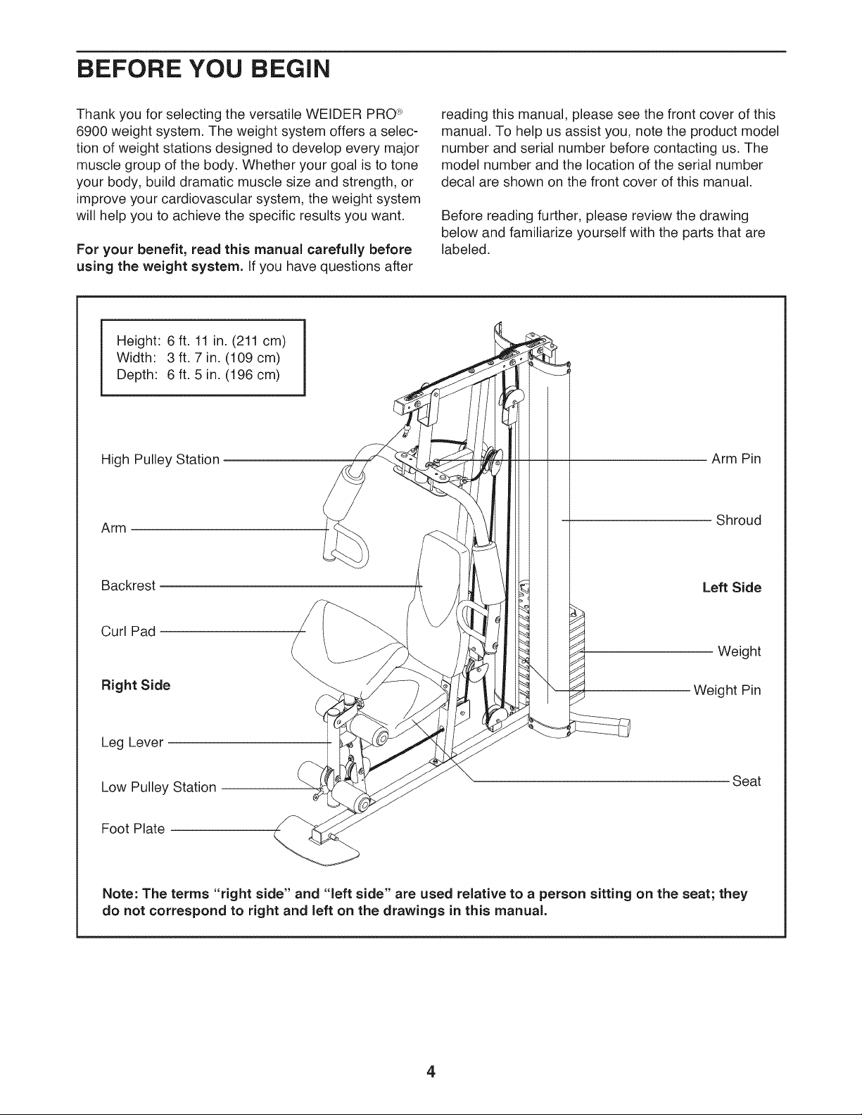
Height: 6 ft. 11 in. (211 cm)
Width: 3 ft. 7 in. (109 cm)
Depth: 6 ft. 5 in. (196 cm)
High Pulley Station
Arm
reading this manual, please see the front cover of this
manual. To help us assist you, note the product model
number and serial number before contacting us. The
model number and the location of the serial number
decal are shown on the front cover of this manual.
Before reading further, please review the drawing
below and familiarize yourself with the parts that are
labeled.
Arm Pin
Shroud
Backrest
Curl Pad
Right Side
Leg Lever
Low Pulley Station
Foot Plate
Note: The terms "right side" and "left side" are used relative to a person sitting on the seat; they
do not correspond to right and left on the drawings in this manual.
Left Side
Weight
Weight Pin
Seat
4
PART iDENTiFiCATiON CHART
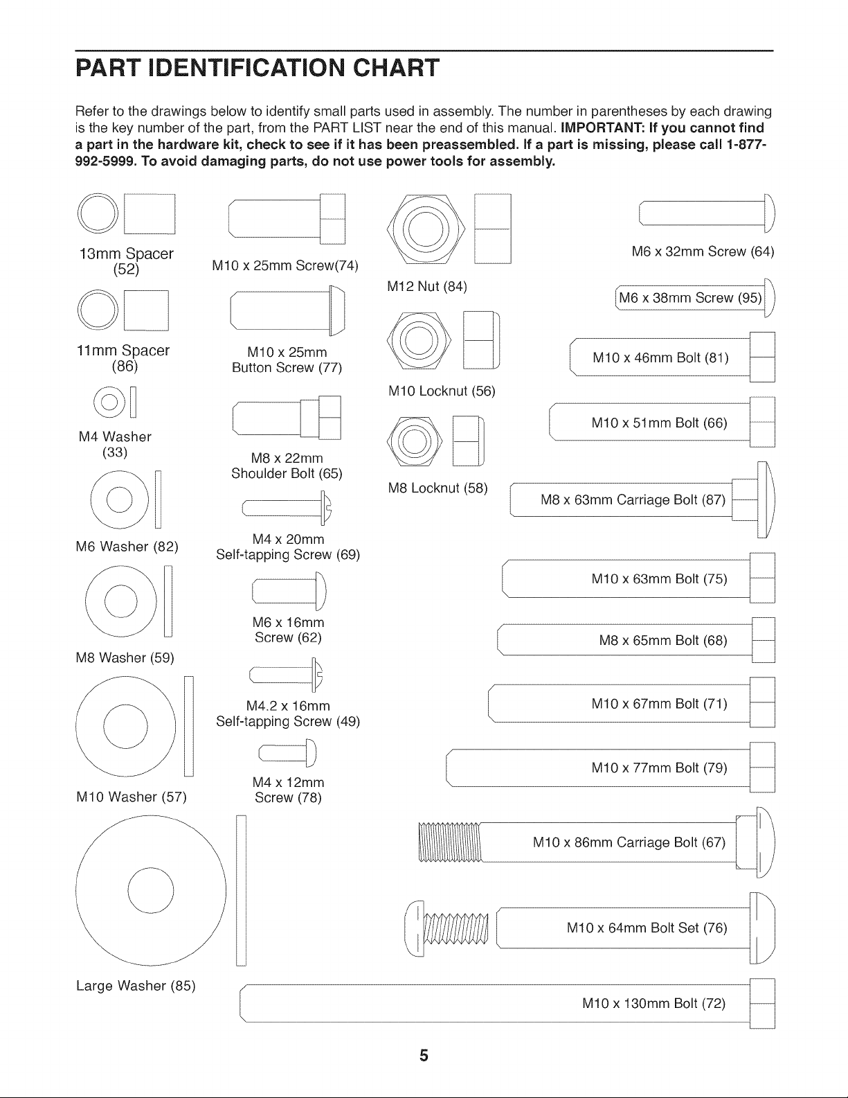
Refer to the drawings below to identify small parts used in assembly. The number in parentheses by each drawing
is the key number of the part, from the PART LIST near the end of this manual, iMPORTANT: If you cannot find
a part in the hardware kit, check to see if it has been preassembled. If a part is missing, please call 1=877=
992=5999. To avoid damaging parts, do not use power tools for assembly.
13mm Spacer
(52)
11mm Spacer
(86)
M4 Washer
(33)
H
M6 Washer (82)
M8 Washer (59)
M10 x 25mm Screw(74)
MIO x 25mm
Button Screw (77)
M8 x 22mm
Shoulder Bolt (65)
M4 x 20mm
Self-tapping Screw (69)
M6 x 16mm
Screw (62)
M12 Nut (84)
M10 Locknut (56)
M8 Locknut (58) (
M6 x 32mm Screw (64)
M6 x 38mm Screw (95)
I M10 x 46mm Bolt (81)
I M10 x 51 mm Bolt (66)
L
M8 x 63mm Carriage Bolt (87)
MIO x 63mm Bolt (75) _
M8 x 65mm Bolt (68)
M10 Washer (57)
Large Washer (85)
M4.2 x 16mm
Self-tapping Screw (49)
M4 x 12ram
Screw (78)
M10 x 67mm Bolt (71)
M10 x 77mm Bolt (79)
M10 x 86mm Carriage Bolt (67)
M10 x 64mm Bolt Set (76)
M10 x 130mm Bolt (72)
5
ASSEMBLY
Assembly requires two persons.
Because of its weight and size, assemble the
weight system in the location where it will be
used. Make sure that there is enough clearance
to walk around the weight system.
Place all parts in a cleared area and remove the
packing materials. Do not dispose of the packing
materials until assembly is completed.
For help identifying small parts, use the PART
IDENTIFICATION CHART on page 5.
The Four Stages of the Assembly Process
Frame Assembly--You will begin by assembling
the base and the uprights that form the skeleton of
the weight system.
Arm Assembly--During this stage you will assem-
ble the arms and the leg lever.
• The following tool(s) (not included) may be
required for assembly:
two adjustable wrenches
one rubber mallet c (_
one standard screwdriver (_:3====_
one Phillips screwdriver
Assembly may be easier if you have a set of
wrenches. To avoid damaging parts, do not use
power tools.
Cable Assembly--During this stage you will attach
the cables and pulleys that connect the arms to the
weights.
Seat Assembly--During the final stage you will
assemble the seat and the backrest.
6
,
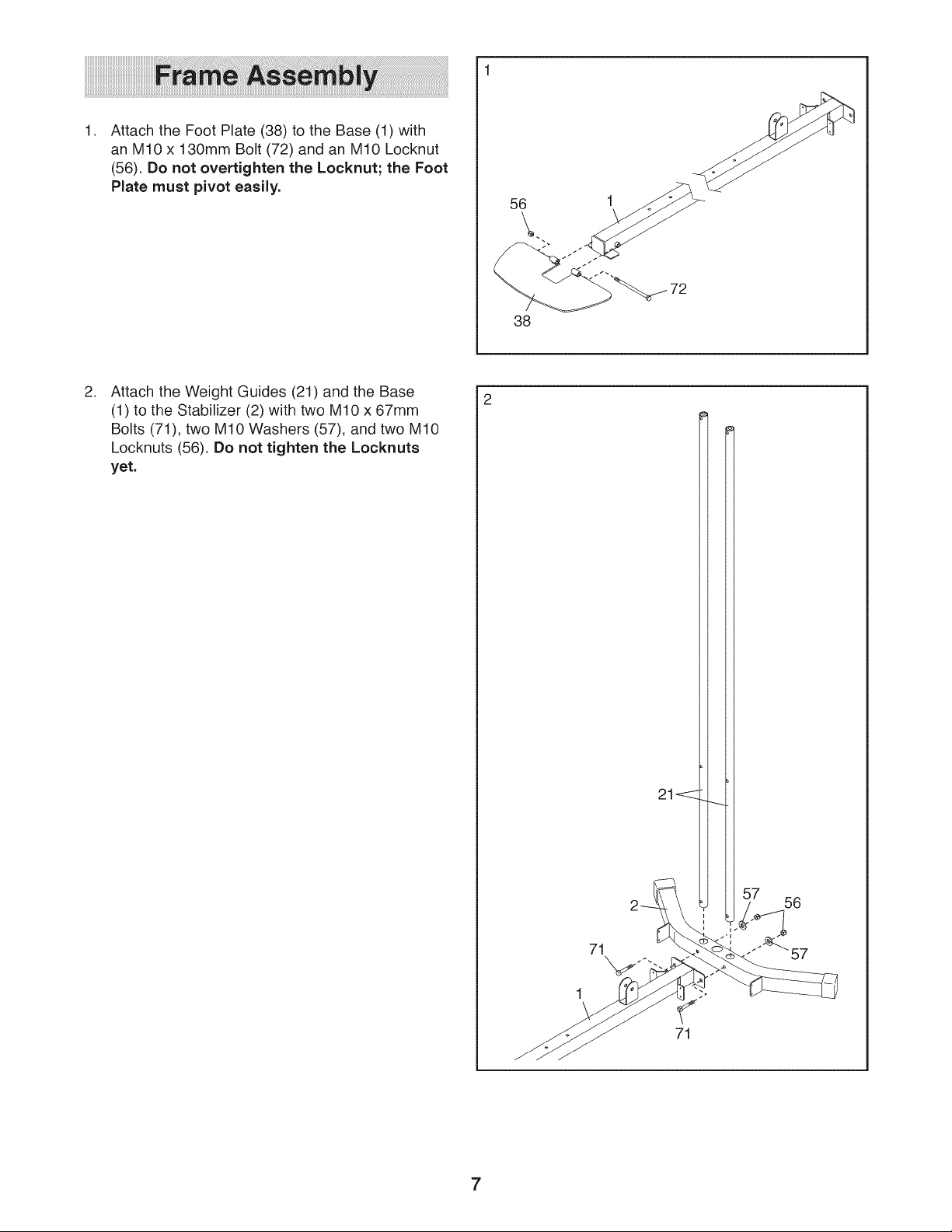
Attach the Foot Plate (38) to the Base (1) with
an M10 x 130mm Bolt (72) and an M10 Locknut
(56). Do not overtighten the Locknut; the Foot
Plate must pivot easily.
,
Attach the Weight Guides (21) and the Base
(1) to the Stabilizer (2) with two M10 x 67mm
Bolts (71), two M10 Washers (57), and two M10
Locknuts (56). Do not tighten the Locknuts
yet.
56
38
71
71
7
,
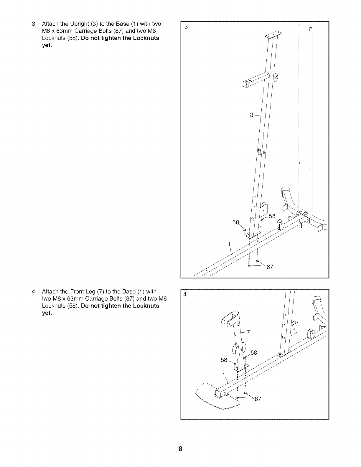
Attach the Upright (3) to the Base (1) with two
M8 x 63mm Carriage Bolts (87) and two M8
Locknuts (58). Do not tighten the Locknuts
yet.
,
Attach the Front Leg (7) to the Base (1) with
two M8 x 63mm Carriage Bolts (87) and two M8
Locknuts (58). Do not tighten the Locknuts
yet.
58
58
87
4
58
87
8
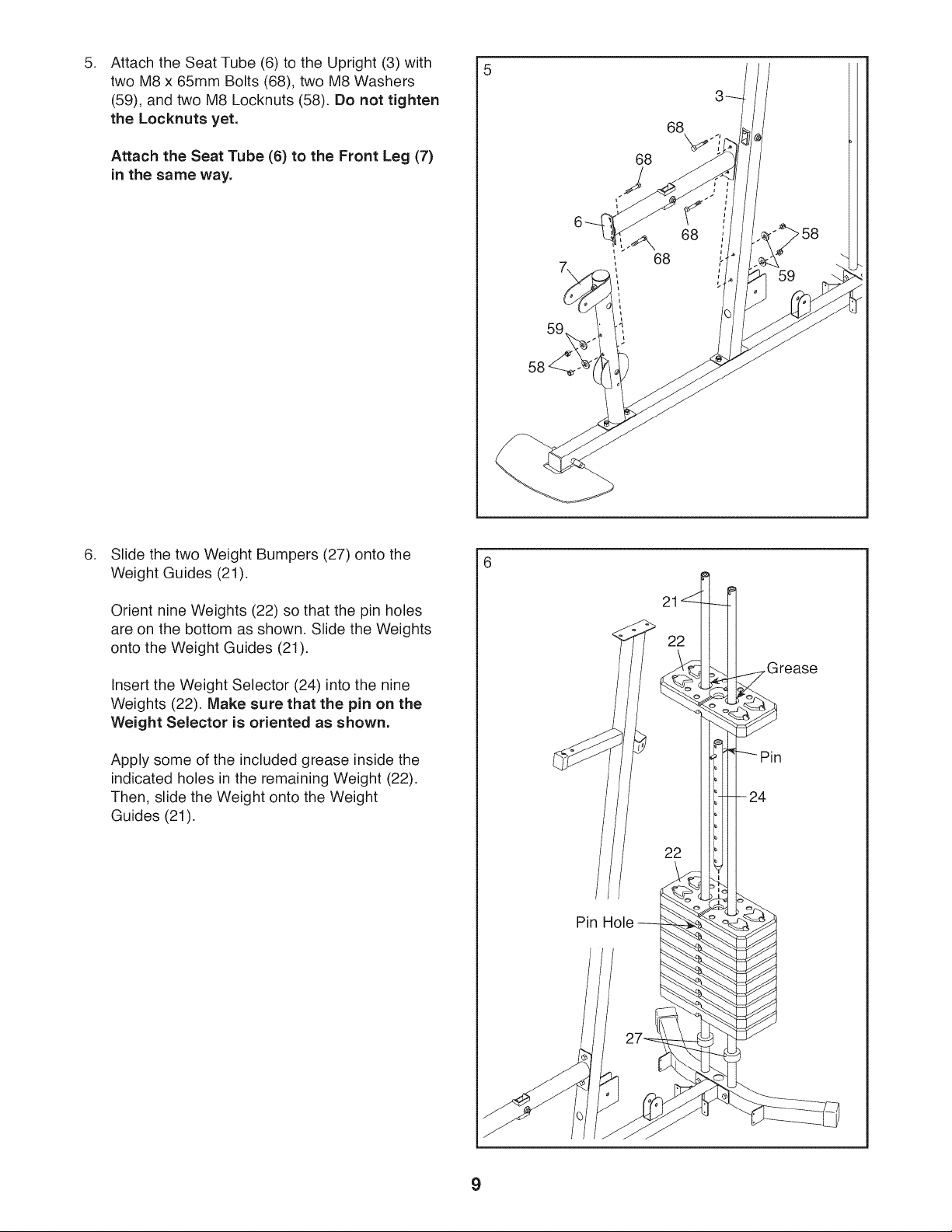
Attach the Seat Tube (6) to the Upright (3) with
5. 5
two M8 x 65mm Bolts (68), two M8 Washers
(59), and two M8 Locknuts (58). Do not tighten
the Locknuts yet.
68
Attach the Seat Tube (6) to the Front Leg (7)
in the same way.
,
Slide the two Weight Bumpers (27) onto the
Weight Guides (21).
68
68
59
Orient nine Weights (22) so that the pin holes
are on the bottom as shown. Slide the Weights
onto the Weight Guides (21).
Insert the Weight Selector (24) into the nine
Weights (22). Make sure that the pin on the
Weight Selector is oriented as shown.
Apply some of the included grease inside the
indicated holes in the remaining Weight (22).
Then, slide the Weight onto the Weight
Guides (21).
Grease
24
22
Pin Hole
9
,
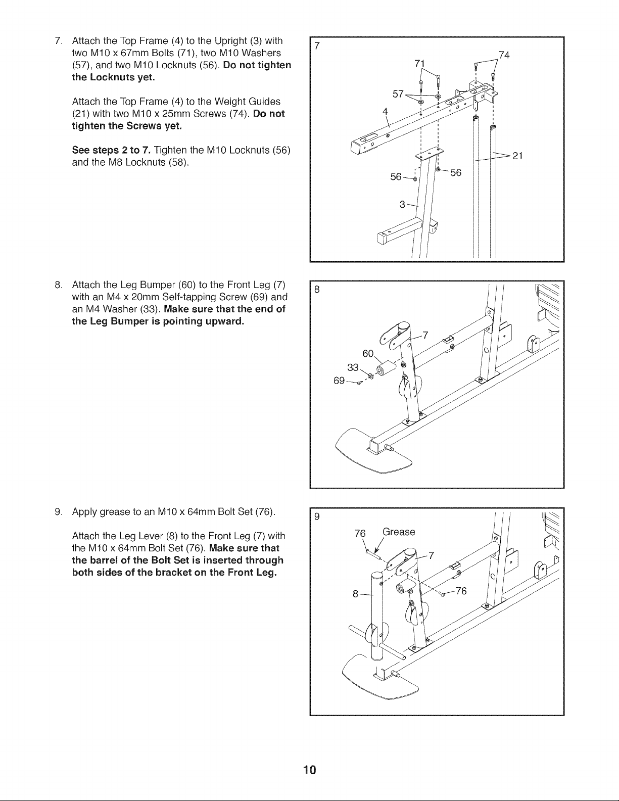
Attach the Top Frame (4) to the Upright (3) with
two M10 x 67mm Bolts (71), two M10 Washers
(57), and two M10 Locknuts (56). Do not tighten
the Locknuts yet.
Attach the Top Frame (4) to the Weight Guides
(21) with two M10 x 25mm Screws (74). Do not
tighten the Screws yet.
See steps 2 to 7. Tighten the M10 Locknuts (56)
and the M8 Locknuts (58).
,
Attach the Leg Bumper (60) to the Front Leg (7)
with an M4 x 20mm Self-tapping Screw (69) and
an M4 Washer (33). Make sure that the end of
the Leg Bumper is pointing upward.
71
74
8
9. Apply grease to an M10 x 64mm Bolt Set (76).
Attach the Leg Lever (8) to the Front Leg (7) with
the M10 x 64mm Bolt Set (76). Make sure that
the barrel of the Bolt Set is inserted through
both sides of the bracket on the Front Leg.
9
76 Grease
10
 Loading...