


R Trademark
Rev.4
12/08/12
KAP
Please do not return product to retailer.
Por favor, no devuelva el producto al lugar de compra.
Veuillez ne pas retourner le produit au détaillant.
1--800--554--6723
Register your product online at:
Registre su producto en línea en:
Enregistrez votre produit en ligne à l’adresse :
www.weedeater.com
Instruction Manual
Manual de Instrucciones
Manuel d’ Instructions
W25CB / W25CF / W25CBK / W25CFK
W25SB / W25SF / W25SBK / W25SFK
ENGLISH ESPAÑOL
For Occasional Use Only
WARNING:
Read and follow all Safety Rules and Operating Instructions before
using this product. Failure to do so can result in serious injury.
ADVERTENCIA:
Lea el manual de instrucciones y siga todas las advertencias e
instrucciones de seguridad. El no hacerlo puede resultar en lesiones
graves.
AVERTISSEMENT:
Lire le manuel d’instructions et bien respecter tous les avertissements et toutes les instructions de sécurité. Tout défaut de le faire
pourrait entraîner des blessures graves.
WEED EATER
9335 Harris Corners Parkway
Charlotte, NC 28269
850 Matheson Blvd. West
Mississauga, Ontario L5V 0B4
WEED EATER
115495027
FRANÇAIS

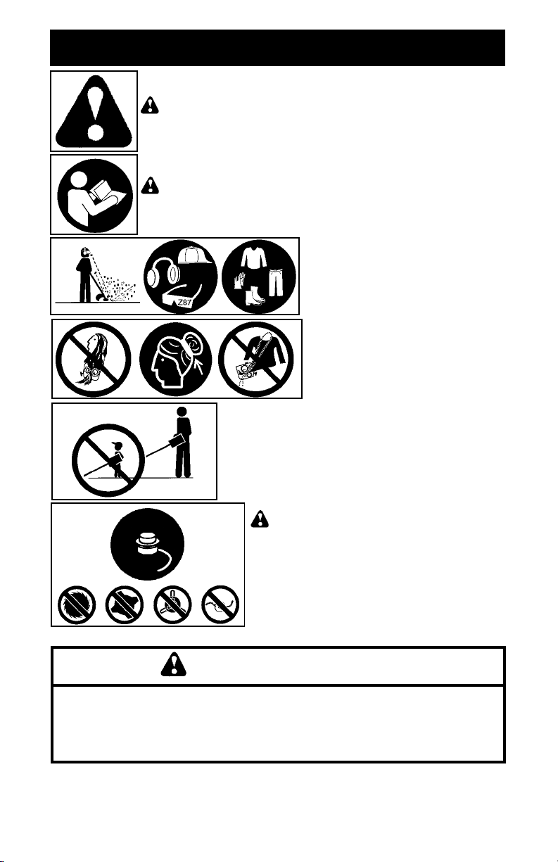
IDENTIFICATION OF SAFETY SYMBOLS
WARNING:
use can cause serious injury.
WARNING:
follow instructions could result in serious injury to the operator and/or
bystanders. Save operator’s manual.
This unit can be dangerous! Careless or improper
Read the operator’s manual before use. Failure to
Trimmer line can throw objects violently.
You can be blinded or injured. Always
wear safety glasses marked Z87.
Always wear hearing protection. We
recommend the use of head protection,
heavy, long pants, long sleeves, boots
and gloves.
Secure hair above shoulder length.
Do not wear jewelry, loose clothing,
or clothing with loosely hanging straps,
ties, tassels, etc. They can be caught in
moving parts.
Never allow children to operate this unit.
WARNING:
head, spool, and recommended trimmer line.
Never use blades, flailing devices, wire, rope,
string, etc. This attachment is designed for line
trimmer use only. Failure to follow these instructions may result in serious injury.
Use only specified trimmer
WARNING
The engine exhaust from this product contains
chemicals known to the State of California to cause
cancer, birth defects or other reproductive harm.
2

IDENTIFICATION OF SAFETY SYMBOLS
Hazard zone for thrown objects.
S Trimmer line throws objects violently.
S You and others can be blinded/injured.
S Keep children, bystanders, and animals 50 feet
(15 meters) away.
WARNING:
use the unit near a flame or sparks (including smoking, open flames, or
work that can cause sparks).
To stop the engine, push and hold the STOP switch in the STOP
position until the engine stops.
Location of idle speed adjustment screw
Fire hazard. Never mix, pour, or store gasoline or
Always stop unit and disconnect spark plug before
cleaning or servicing.
When servicing unit, use only identical replacement
parts.
Store unit indoors in a high, dry place out of the reach of
children.
Use unleaded gasoline and two--stroke oil mixed at a ratio of
40:1 (2.5%).
3

IDENTIFICATION OF SAFETY SYMBOLS
Starting
symbols
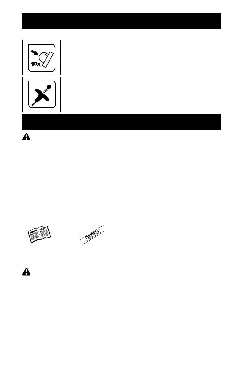
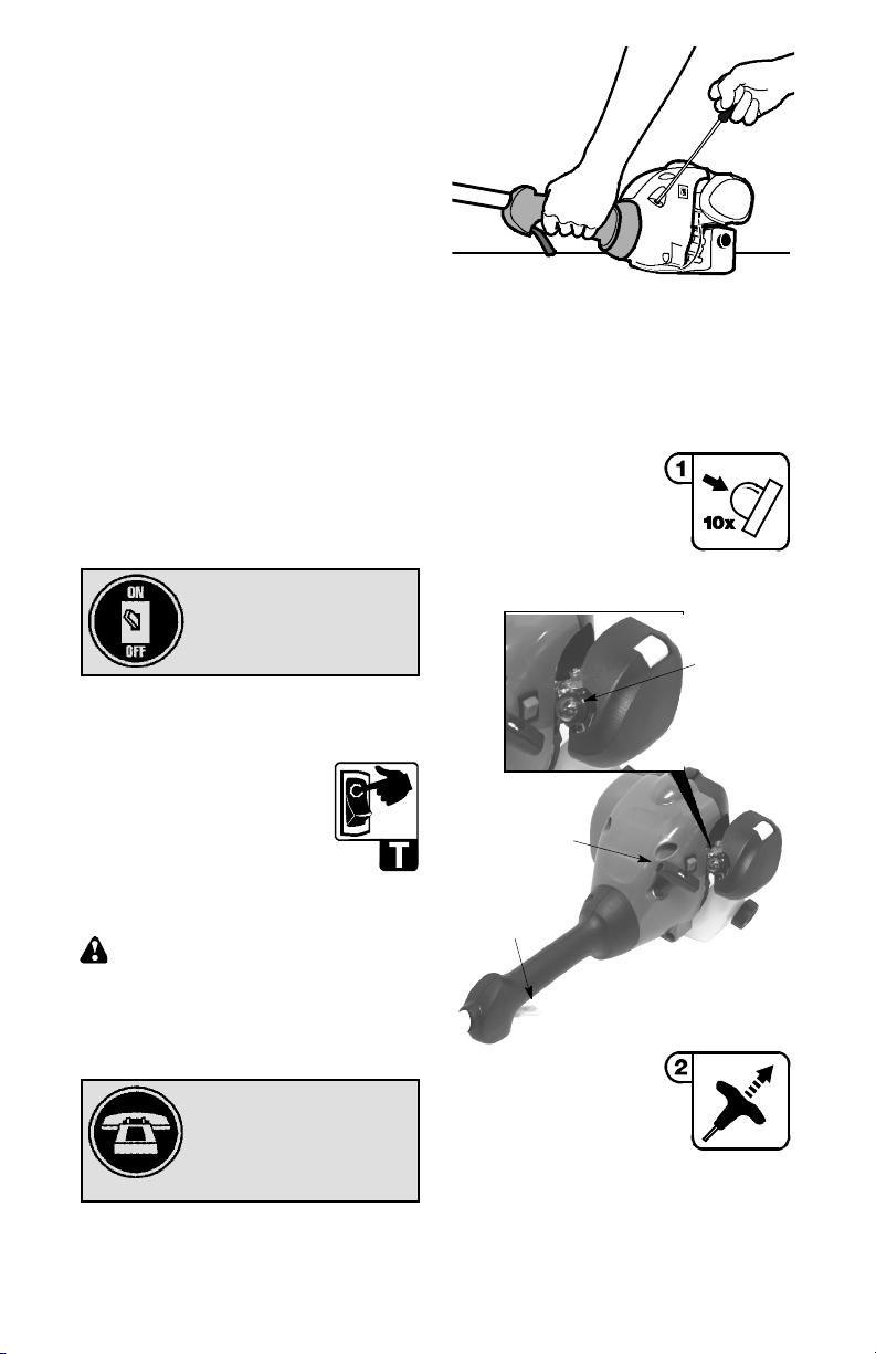
Press primer bulb 10 times firmly (first push will move the primer bulb
slightly creating a “click” sound).
While holding the unit in starting position, pull starter rope handle rapidly
until engine starts.
SAFETY RULES
WARNING:
appliances, basic safety precautions must always be followed to reduce the risk of fire and
serious injury. Read and follow all instructions.
Operator is responsible for following instructions and warnings on unit and in manual.
Read entire instruction manual before using
unit! Be thoroughly familiar with the controls
andthe proper use of the unit. Restrict the use
of this unit to persons who have read, understand, and will follow the instructions and
warnings on the unit and in the manual. Never
allow children to operate this unit.
INSTRUCTION
MANUAL
WARNING:
ing devices. This unit is designed for line trimmer use only.Use of any other accessories or
attachments will increase the risk of injury.
If situations occur which are not covered in
this manual, use care and good judgment. If
you need assistance, contact your authorized
service dealer or call 1-800-554--6723.
OPERATOR SAFETY
S Dress properly. Always wear safety glasses
or similar eye protection when operating, or
performing maintenance, on your unit (safety
glasses are available). Eye protectionshould
be marked Z87.
S Always wear hearing protection.
S Always wear face ordust mask if operation is
dusty.
S Always wear heavy, longpants, longsleeves,
boots, and gloves. Wearing safety legguards
is recommended.
When using gardening
SAFETY INFORMATION
ON THE UNIT
Never use blades or flail-
S Always wear foot protection. Do not go bare-
foot or wear sandals. Stay clear of spinning
line.
S Securehairaboveshoulder length. Secureor
remove loose clothing or clothing with loosely
hanging ties, straps, tassels, etc. They can
be caught in moving parts.
S Being fully covered also helps protect you
from debris and pieces of toxic plants thrown
by spinning line.
S Stay alert. Do not operate this unit when you
are tired, ill, upset or under the influence of alcohol, drugs, or medication. Watch what you
are doing; use common sense.
S Never start or run inside a closed room or
building. Breathing exhaust fumes can kill.
S Keep handles free of oil and fuel.
UNIT / MAINTENANCE SAFETY
S Disconnect the spark plug before performing
maintenance except idle speed adjustments.
S Look for and replace damaged or loose parts
before each use. Look for and repair fuel
leaks before use. Keep in good working
condition.
S Replace trimmer head partsthat arechipped,
cracked, broken, or damaged in any other
way before using the unit.
S Maintainunit accordingto recommendedpro-
cedures. Keep cutting line at proper length.
S Use only recommended WEED EATER
brand line. Never use wire, rope, string, etc.
S Install required shield properly before using
the unit. Use only specified trimmer head;
make sure it is properly installed and securely
fastened.
S Make sure unit is assembled correctly as
shown in this manual.
S Make idle speed adjustments with lower end
supported to prevent line from contacting any
object.
S Keep others away when making idle speed
adjustments.
S Use only recommended WEED EATER ac-
cessories and replacement parts.
4

S Have all maintenance and service not ex-
plained in this manualperformedby an authorized service dealer.
FUEL SAFETY
S Mix and pour fuel outdoors.
S Keep away from sparks or flames.
S Use a container approved for fuel.
S Do not smoke or allow smoking near fuel or
the unit.
S Avoid spillingfuel or oil. Wipe upall fuel spills.
S Move at least 10 feet (3 meters) away from
fueling site before starting engine.
S Stop engine and allow to cool before remov-
ing fuel cap.
S Always store gasoline in a container ap-
proved for flammable liquids.
S Look for and repair fuel leaks before use.
S Ensure that fuel cap is securely tightened
after adding fuel.
CUTTING SAFETY
WARNING:
each use. Remove objects (rocks, broken
glass, nails, wire, etc.) which can be thrown
by or become entangled in line. Hard objects
can damage the trimmer head and be thrown
causing serious injury.
S Keep others including children, animals,
bystanders, and helpers at least 50 feet (15
meters) away. Bystanders shouldbeencouraged to wear safety glasses. Stop engine
immediately if you are approached.
S Use only for trimming, scalping, mowing and
sweeping. Do not use for edging, pruning or
hedge trimming.
S Keep firm footing and balance. Do not over-
reach.
S Keepall parts of your body away from muffler
and spinning line. Keep engine below waist
level. A hot muffler can cause serious burns.
S Models W25CB, W25CF, W25CBK,
W25CFK: Cut from your right to your left.
Cutting on left side of the shield will throw
debris away from the operator.
S Models W25SB, W25SF, W25SBK,
W25SFK: Cut from your left to your right.
Cutting on right side of the shield will throw
debris away from the operator.
S Use only in daylight or good artificial light.
S Use only for jobs explained in this manual.
Inspect the area before
TRANSPORTING AND STORAGE
S Allow engine to cool; secure unit before stor-
ing or transporting in vehicle.
S Empty the fuel tank before storing or trans-
portingtheunit. Use up fuelleft in the carburetorby startingtheengine and letting it rununtil
it stops.
S Store unit and fuel in area where fuel vapors
cannot reachsparks or openflames from water heaters, electric motors or switches, furnaces, etc.
S Store unit solinelimiterbladecannot acciden-
tallycause injury. The unit canbehung by the
shaft.
S Store unit out of reach of children.
SAFETY NOTICE:
through prolonged use of gasoline powered
hand tools could cause blood vessel or nerve
damage in the fingers, hands, and joints of
people prone to circulation disorders or abnormal swellings. Prolonged use in cold weather
has been linked to blood vessel damage in
otherwise healthy people. If symptoms occur
such as numbness, pain, loss of strength,
change in skin color or texture, or loss of feeling
in the fingers, hands, or joints, discontinue the
use of this tool and seek medical attention. An
anti--vibration system does not guarantee the
avoidance of these problems. Users who operatepowertools on a continualand regularbasis
must monitor closely their physical condition
and the condition of this tool.
SPECIAL NOTICE:
with a temperature limiting muffler and spark arresting screenwhich meets the requirements of
California Codes 4442and4443. All U.S. forest
land and the states of California, Idaho, Maine,
Minnesota, New Jersey, Oregon, and Washington require by law that many internal combustion engines be equipped with a spark arresting
screen. If you operate in a locale where such
regulations exist, you are legally responsible for
maintaining the operating condition of these
parts. Failure to do so is a violation of the law.
For normal homeowner use, the muffler and
spark arresting screen will not require any service. After 50 hours ofuse, we recommend that
your muffler be serviced or replaced by your authorized service dealer.
Exposure to vibrations
This unit is equipped
ASSEMBLY
CAUTION:
all steps to ensure your unit is properly assembled and all fasteners are secure.
Examine parts for damage. Do not use damaged parts.
NOTE:
missing or damaged, call 1-800-554-6723.
It is normal for the fuel filter to rattle in the
empty fuel tank.
If received assembled, repeat
If you need assistance or find parts
Finding fuel or oil residue on muffler is normal
due to carburetor adjustments and testing
done by the manufacturer.
SHAFT ASSEMBLY
(Models W25CBK, W25CFK,
W25SBK, W25SFK)
CAUTION:
the unit on a flat surface for stability.
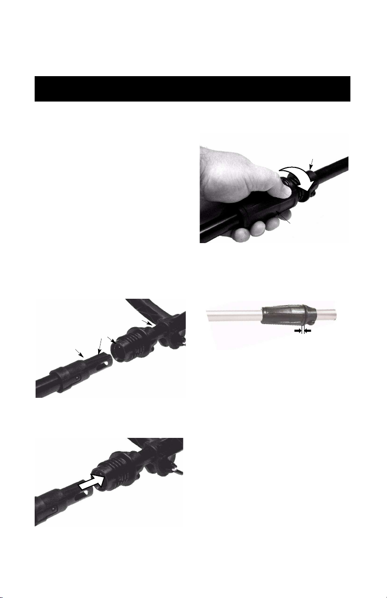
1. Align grooves on upper and lower shafts.
When assembling shaft, place
5
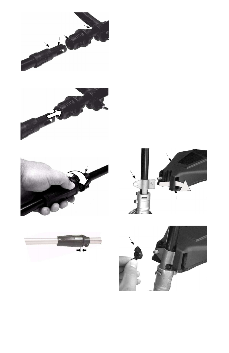
Upper Shaft
Upper
Locking
Shield
Grooves
Lower Shaft
2. Push the two shafts together until the lower
shaft is fully seated in the upper shaft.
3. Slide lower locking sleeve assembly over
upper locking sleeve assembly and tighten by turning clockwise.
Sleeve Assembly
2. Rotate the handle on the shaft to anupright
position; retighten wing nut.
ADJUSTING THE HANDLE
(Models W25CBK, W25CFK,
W25SBK, W25SFK)
CAUTION:
dle, be sure it remains above the upper locking sleeve and below the mark or arrow on the
shaft.
1. Loosen wing nut on handle.
2. Rotate the handle on the shaft to anupright
position; retighten wing nut.
When adjusting the assist han-
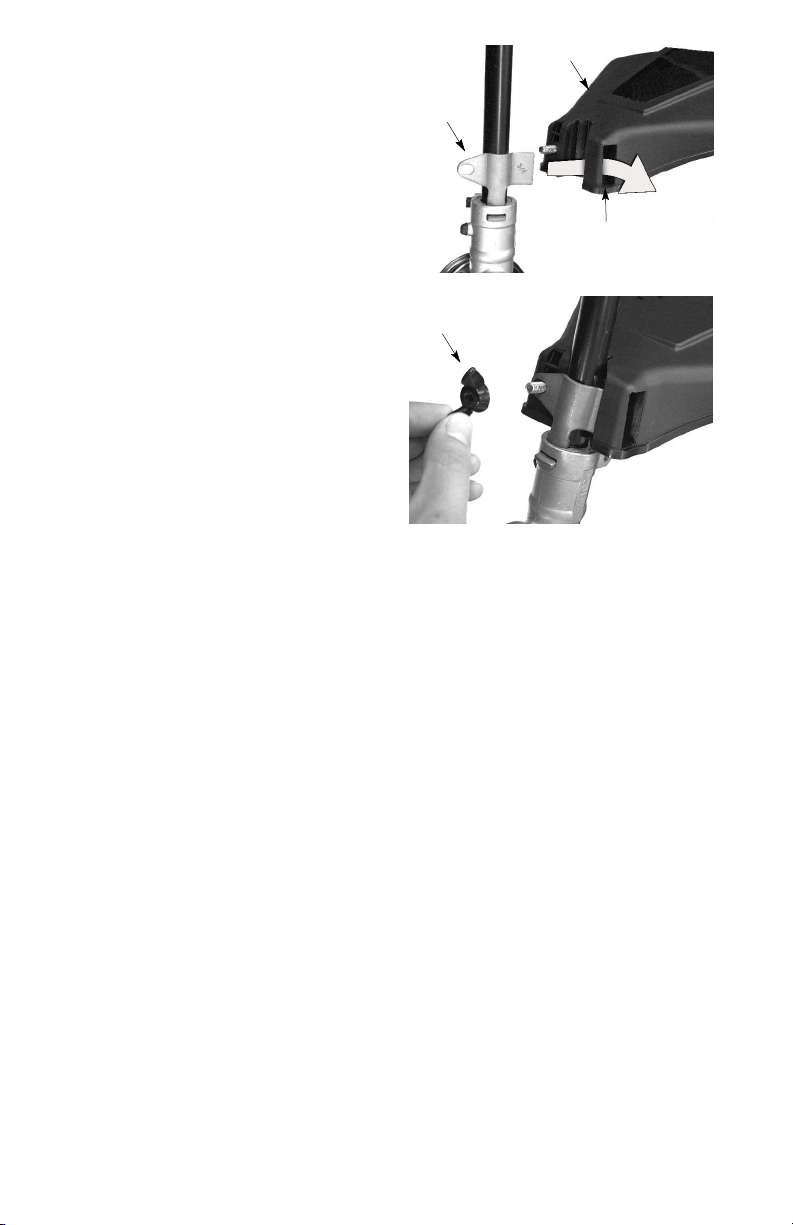
ATTACHING SHIELD
CAUTION:
installed. The shield provides partial protection
from the risk of thrown objects to the operator
and others and is equipped with a line limiter
blade which cuts excess line to the proper
length. The line limiter blade (on underside of
shield) is sharp and can cut you.
For proper orientation of shield, see KNOW
YOUR TRIMMER illustration in OPERATION
section.
1. Remove wing nut from shield.
2. Insert bracket into slot as shown.
3. Pivot shielduntilbolt passes through hole in
bracket.
4. Securely tighten wing nut onto bolt.
Bracket
The shield must be properly
Lower Locking
Sleeve Assembly
NOTE:
not tighten (gap is more than 1/4″), the upper
and lower shafts are not fully seated.
If lower locking sleeve assembly will
Gap is more than 1/4″
ADJUSTING THE HANDLE
(Models W25CB, W25SB, W25CF,
W25SF)
CAUTION:
be sure it remains above the safety label and
below the mark or arrow on the shaft.
1. Loosen wing nut on handle.
When adjusting the assisthandle,
Slot
Wing Nut
6

OPERATION
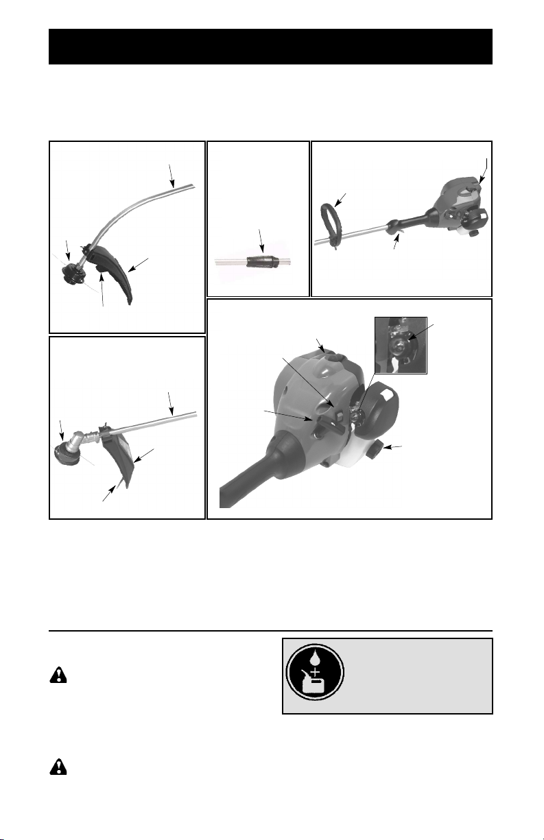
KNOW YOUR TRIMMER
READ THIS INSTRUCTION MANUAL AND SAFETYRULES BEFORE OPERATING YOUR UNIT.
Compare the illustrations with your unit to familiarize yourself with the location of the various controls
and adjustments. Save this manual for future reference.
Models:
W25CB, W25CF,
W25CBK, W25CFK
Head
Line Limiter Blade
Models:
W25SB, W25SF,
W25SBK, W25SFK
Trimmer
Head
Line Limiter Blade
Shaft
Shield
Shaft
Shield
Models:
W25CBK, W25CFK,
W25SBK, W25SFK
Locking Sleeve
AssemblyTrimmer
STOP Switch
Starter
Handle
STOP SWITCH
The STOP switch is usedto stop the engine. To
stop the engine, push and hold the switch inthe
STOP position until the engine stops.
Muffler
Assist Handle
Throttle Trigger
Fuel Mix
Fill Cap
Primer Bulb
Spark Plug
PRIMER BULB
The PRIMER BULB removes air from thecarburetor and fuel lines and fills them with fuel.
This allows you to start the engine with fewer
pulls on the starter rope. Activate the primer
bulb by pressing it and allowing it to return to
its original form.
BEFORE STARTING ENGINE
WARNING:
information in the safety rules before you
begin. If you do not understand the safety
rules, do not attempt to fuel your unit. Call
1-800-554-6723.
Be sure to read the fuel
FUELING ENGINE
WARNING:
when refueling.
Remove fuel cap slowly
HELPFUL TIP
To obtain the correct oil mix
ratio, pour 3.2 ounces of
2--cycle synthetic oil into
one gallon of fresh gas.
IMPORTANT:
operate on unleaded gasoline with a minimum
87 octane (R+M/2 method), with ethanol
blended up to 10%maximum by volume (E-10).
Before operation, gasolinemust be mixedwith a
good quality synthetic 2-cycle air-cooled engine
oil designed to be mixed at a ratio of 40:1.
Poulan/WEED EATER brand synthetic oil is
recommended. Mix gasoline and oil at a ratio of
40:1. A 40:1 ratio is obtained by mixing 3.2 fluid
ounces of oil with 1 gallon of unleaded gasoline.
DO NOT USE automotive oil or marine oil.
These oils will cause engine damage. When
mixing fuel, follow instructions printed on
container. Once oil is added to gasoline, shake
container momentarily to assure that the fuel is
thoroughly mixed.
This equipment is designedto
7

Always read and follow the safety rules relating
2.While
holding
the
unit
to fuel before fueling your unit. Purchase fuel in
quantities that can be used within 30 days to
assure fuel freshness.
CAUTION:
your unit. This will cause permanent engine
damageand void the limited warranty. Do not
use alternate fuels such as ethanol blends
above 10% by volume (E-15, E-85) or any
methanol blended fuel. Use of these fuelscan
cause major engine performance and durability problems.
Never use straight gasoline in
HELPFUL TIP
If your engine switch reads
“push to stop”, it is always
in the ON position.
HOW TO STOP YOUR UNIT
S To stop the engine, push
and hold the STOP switch in
the STOP position until the
engine stops.
Starter
Handle
Thottle
Trigger
Primer
Bulb
HOW TO START YOUR UNIT
WARNING:
turn whilestarting the engine. Avoid any contact with the muffler. A hot muffler can cause
serious burns.
The trimmer head will
HELPFUL TIP
If your engine still does not
start after following these
instructions, please call
1--800--554--6723.
STARTING
POSITION
STARTING A COLD ENGINE (or a hot
engine after running out of fuel)
NOTE:
pull throttle trigger until the engine starts. If
throttle trigger is pulled before the engine
starts, the engine will not start!
1. Press primer bulb
Set unit on a flat surface. DO NOT
10 times firmly
(first push will move the
primer bulbslightly creating
a “click” sound).
in starting position as
shown, pull starter rope
handle rapidly until engine starts. Do not pull
starter rope more than
10 times.
3. Once the engine starts, allow it to run approximately 30 seconds, then pull the
throttle trigger to disengage the starting
system.
4. If the engine does not start, proceed to
STARTING A HOT ENGINE.
STARTING A HOT ENGINE
1. Pull and release throttle trigger to ensure
that the cold starting system has been disengaged.
2. When engine is hot (operated in the last
15 minutes), hold the unit in starting positionas shownand pull starter rope handle
rapidly until engine starts. Do not pull
starter rope more than 10 times.
3. If the engine does not start, proceed to
STARTING A FLOODED ENGINE.
NOTE:
can be used within 15 minutes after the unit is
turned off. If the unit sits for more than 15 minutes without being used, it will be necessary to
start the unit by following the steps under
STARTING A COLD ENGINE.
Normally, the hot starting procedure
STARTING A FLOODED ENGINE
Fully squeeze throttle trigger. Pull the starter
rope handle repeatedly while squeezing
throttle trigger until engine starts and runs.
This could require pulling the starter handle
many times depending on how badly the unit
is flooded. If the unit still doesn’t start, refer to
TROUBLESHOOTING TABLE or call
1-800-554-6723.
8
OPERATING INSTRUCTIONS
Tipof
line
does
Line
crowded
into
It is recommended that the engine not be operated for longer than 1 minute at full throttle.
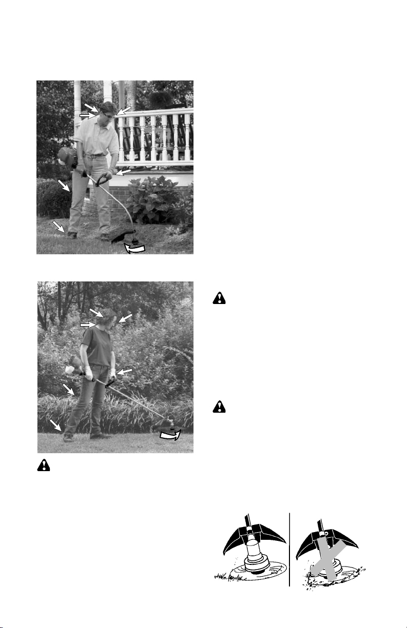
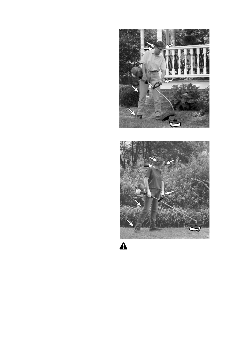
OPERATING POSITIONS
Models W25CB, W25CF, W25CBK,
W25CFK:
ALWAYS WEAR:
Hearing protection
Hair above
shoulders
Long
Pants
Heavy
Shoes
Models W25SB, W25SF, W25SBK,
W25SFK:
ALWAYS WEAR:
Hearing protection
Hair above
shoulders
Long
Pants
Heavy
Shoes
Cut from your left to your right.
WARNING:
protection and eye protection. Never lean
over the trimmer head. Rocks or debris can
ricochet or be thrown into eyes and face and
cause blindness or other serious injury.
Maintain firm footing and hold trimmer with
both hands with right hand on the rear handle/
throttle control and the left hand on the front
handle. Always keep engine and trimmer
head below waist level.
Do not run the engine at a higher speed than
necessary. The cutting line will cut efficiently
when the engine is run at less than full throttle.
At lower speeds, there is less engine noise and
vibration. The cutting line will last longer and will
be less likely to “weld” onto the spool.
Eye protection
Gloves
Cut from
your right
to your left.
Eye protection
Gloves
Always wear hearing
Always release the throttle trigger and allow the
engine to return to idle speed when not cutting.
To stop engine:
S Release the throttle trigger.
S Push and hold the STOP switch in the
STOP position until the engine stops.
TRIMMER LINE ADVANCE
(Models W25CB, W25SB, W25CBK,
W25SBK)
The trimmer line will advance approximately 2
inches (5 cm) each time the bottom of the
trimmerhead is tapped on the ground with the
engine running at full throttle.
The most efficient line length is the maximum
length allowed by the line limiter.
Always keep the shield in placewhen the tool
is being operated.
To advance line:
S Operate the engine at full throttle.
S Holdthe trimmer headparallel to andabove
the grassy area.
S Tap the bottom of the trimmer head lightly
on the ground one time. Approximately 2
inches (5 cm) of line will be advanced with
each tap.
Always tap the trimmer head on a grassy
area. Tapping on surfaces such as concrete
or asphalt can cause excessive wear to the
trimmer head.
If the line is worn down to 2 inches (5 cm) or
less, more than one tap will be required to obtain the most efficient line length.
WARNING:
W25SB, W25CBK, W25SBK, use only 0.080
inch (2 mm) diameter line.Other sizesof linewill
not advance properly and will result in improper
cutting head function or can cause serious
injury. For models W25CF, W25SF, W25CFK,
W25SFK, use only 0.095 inch (2.4 mm) diameter cut length line. Do not use other materials
such as wire, string, rope, etc. Wire can break
off during cutting and become a dangerous projectile that can cause serious injury.
For models W25CB,
CUTTING METHODS
WARNING:
and do not crowd the line when cuttingaround
hard objects (rock, gravel, fence posts, etc.),
whichcan damage the trimmerhead,become
entangled in the line, or be thrown causing a
serious hazard.
S The tip of the line does the cutting. You will
achieve the best performance and mini-
mum line wear by not crowding the line into
the cutting area. The right and wrong ways
are shown below.
the cutting.
Right
Use minimum speed
work area.
Wrong
9

S The line will easily remove grass and
weeds from around walls, fences, trees and
flower beds, but it also can cut the tender
bark of trees or shrubs and scar fences. To
help avoid damage especially to delicate
vegetation or trees with tender bark,
shorten line to 4--5 inches (10--13 cm) and
use at less than full throttle.
S For trimming or scalping, use less than full
throttle to increase line life and decrease
head wear, especially:
S During light duty cutting.
S Near objects around which the line can
wrap such as small posts, trees or fence
wire.
S Formowing or sweeping,use full throttlefor
a good clean job.
TRIMMING -- Hold the bottom of the trimmer
head about 3 inches (8 cm) above the ground
and at an angle. Allow only the tip of the line to
make contact. Do not force trimmer line into
work area.
Trimming
3 inches (8 cm)
above ground
SCALPING -- The scalping technique removes unwanted vegetationdown to the
ground. Hold the bottom of the trimmer head
about 3 inches (8 cm) above the ground and
at an angle. Allow the tipof the lineto strikethe
ground around trees, posts, monuments, etc.
This technique increases line wear.
Scalping
MOWING -- Your trimmer is ideal for mowing
in places conventional lawn mowers cannot
reach. In the mowing position, keep the line
parallel to the ground. Avoid pressing the
head into the ground as this can scalp the
ground and damage the tool.
Mowing
SWEEPING -- The fanning action of therotat-
ing line can be used for a quick and easy
clean up. Keep the line parallel to and above
the surfaces being swept and move the tool
from side to side.
Sweeping
MAINTENANCE
WARNING:
plug before performing maintenance except
for idle speed adjustments.
If any dealer other than an authorized
service dealer performs work on the
product, WEED EATER may not pay for
repairs under warranty. It is your responsibility to maintain and perform
general maintenance.
Disconnect the spark
HELPFUL TIP
IMPORTANT:
repairs other than the recommended maintenance
described in the instruction
manual performed by an
authorized service dealer.
Have all
CHECK FOR LOOSE
FASTENERS AND PARTS
S Spark Plug Boot
S Air Filter
S Housing Screws
S Assist Handle Screws
S Debris Shield
S Fuel Cap
CHECK FOR DAMAGED OR
WORN PARTS
Contact an authorized service dealer for replacement of damaged or worn parts.
S STOP Switch -- Ensure STOP switch func-
tions properly by pushing and holding the
switch in the STOP position. Make sure engine stops. Restart engine and continue.
S Fuel Tank -- Discontinue use of unit if fuel
tank, fuel cap, and/or fuel ines shows signs
of damage or leaks.
S Debris Shield -- Discontinue use of unit if
debris shield is damaged.
10

INSPECT AND CLEAN UNIT AND
LABELS
S After each use, inspect complete unit for
loose or damaged parts. Clean the unit and
labels using a damp cloth with a mild deter-
gent.
S Wipe off unit with a clean dry cloth.
CLEAN AIR FILTER
A dirty air filter decreases engine performance and increases fuel consumption and
harmful emissions. Always clean after every
5 hours of operation.
1. Clean the air filter cover and the area
around it to keep dirt from falling into the
carburetor chamber when the cover is
opened.
2. Open air filter cover by pushing button
(see illustration). Remove air filter.
NOTE:
producing harmful evaporative emissions, do
not clean filter in gasoline or other flammable
solvent.
3. Wash the filter in soap and water.
4. Allow filter to dry.
5. Replace air filter and close cover.
To avoid creating a fire hazard or
Button
Air Filter
MUFFLER AND SPARK ARRESTING SCREEN
As your unit is used, carbon deposits build up
on the muffler and spark arresting screen.
For normal homeowner use, however, the
muffler and spark arresting screen will not require any service.
After 50 hours of use, we recommend that
your muffler be serviced or replaced by your
authorized service dealer.
REPLACE SPARK PLUG
Replace the spark plug each year to ensure
the engine starts easier and runs better. Set
spark plug gap at 0.025 inch (0.6 mm). Ignition timing is fixed and nonadjustable.
NOTE:
spark ignition system complies with the Canadian standard ICES--002.
1. Twist, then pull off spark plug boot.
2. Remove spark plug from cylinder and dis-
3. For U.S. models only: Replace with
4. Tighten securely with a 3/4 inch (19 mm)
5. Reinstall the spark plug boot.
For Canadian models only: This
card.
Champion RCJ-6Y.
For Canadian models only: Replace
with Champion QCJ--6Y.
socket wrench.
Air Filter Cover
SERVICE AND ADJUSTMENTS
LINE REPLACEMENT
(Models W25CB, W25SB, W25CBK,
W25SBK)
WARNING:
W25SB, W25CBK, W25SBK, use only 0.080
inch (2 mm) diameter line.Other sizesof linewill
not advance properly and will result in improper
cutting head function or can cause serious
injury. For models W25CF, W25SF, W25CFK,
W25SFK, use only 0.095 inch (2.4 mm) diameter cut length line. Do not use other materials
such as wire, string, rope, etc. Wire can break
off during cutting and become a dangerous projectile that can cause serious injury.
1. Remove spool by firmly pulling on tap
button.
2. Clean entire surface of hub and spool.
3. Replace witha pre-wound spool, or cuttwo
lengths of
diameter WEED EATER brand line.
4. Insert ends of the lines about 1/2 inch (1
cm) into the small holes on the inside of
spool.
12-1/2
For models W25CB,
feet of 0.080 inch (2 mm)
Spool
Line in notch
Line exit hole
11
Line in notch
Hub
Small
Holes
Line exit hole

5. Wind the line evenly and tightly onto the
spool. Wind in the direction of the arrows
found on the spool.
6. Push the lines into the notches, leaving 3
to 5 inches (7 -- 12 cm) unwound.
7. Insert the lines into the the exit holes in
the hub as shown in the illustration.
8. Align the notches with the line exit holes.
9. Push spool into hub until it snaps into
place.
10. Pull the lines extending outside of the hub
to release the lines from the notches.
LINE REPLACEMENT
(Models W25CF, W25SF, W25CFK,
W25SFK)
5. Pullends of lineuntil line is tight. Correctly
installed line will be the same length on
both ends.
REPLACING THE TRIMMER HEAD
(Models W25CB, W25SB, W25CBK,
W25SBK)
1. Hold the dust cup with a wrench to keep
the shaft from turning whileremovingand
installing trimmer head.
Dust Cup
WARNING:
W25SB, W25CBK, W25SBK, use only 0.080
inch (2 mm) diameter line.Other sizesof linewill
not advance properly and will result in improper
cutting head function or can cause serious
injury. For models W25CF, W25SF, W25CFK,
W25SFK, use only 0.095 inch (2.4 mm) diameter cut length line. Do not use other materials
such as wire, string, rope, etc. Wire can break
off during cutting and become a dangerous projectile that can cause serious injury.
For unit to operate properly, the cutting line
should be replaced when line becomes worn
to less than 3 inches in length from the edge of
each side of the cutting head.
1. Remove and discard worn line before
installing new line.
2. Clean entire surface of cutting head.
3. Insert ends of line into the two guide holes
on front of cutting head.
Guide
Hole
4. Continue to feed line through the guide
holes until the line is fully extended
through the side exit holes.
For models W25CB,
Guide
Hole
Side Exit Hole
2. Remove trimmer head by turning counterclockwise (looking from bottom of unit).
3. Thread replacement trimmer head onto
the shaft by turning clockwise. Tighten
until secure.
REPLACING THE TRIMMER HEAD
(Models W25CF, W25SF, W25CFK,
W25SFK)
1. Alignholein the dustcup with thehole in the
side of the gearbox by rotatingthe dustcup.
2. Insert a small screwdriver into aligned
holes. This will keep the shaft from turning
whileremoving and installing trimmerhead.
Screwdriver
3. While holding the screwdriver in position,
remove trimmer head by turning clockwise
(looking from bottom of unit).
4. Thread replacement trimmer head onto the
shaft by turning counterclockwise. Tighten
until secure.
5. Remove the screwdriver.
IDLE SPEED ADJUSTMENT
Side Exit
Hole
WARNING:
making idle speed adjustments. The trimmer
head will be spinning during this procedure.
Wear your protective equipment and observe
all safety precautions.
The carburetor has been carefully set at the
factory. Adjustment of the idle speed may be
necessary if you notice any of the following
conditions:
S Engine will not idle when the throttle is re-
leased.
Keep others away when
12

Make adjustments with the unit supported so
the cutting attachment is off the ground and
willnot make contact with anyobject. Hold the
unit by hand while running and makingadjustments. Keep all parts of your body away from
the cutting attachment and muffler.
To adjust idle speed:
Start engine and allow to warm up 4-- 5
minutes while heavy cutting, or 10--15
minutes moderate cutting. Allow engine to
idle. Adjust speed until engine runs without
stalling (idle speed too slow).
S Turn idle speed screw clockwise to in-
crease enginespeed if engine stalls or dies.
S Turn idle speed screw counterclockwise to
decrease engine speed.
STORAGE
Idle Speed Screw
If you require further assistance or areunsure
about performing this procedure, contact an
authorized service dealer or call
1--800-- 554--6723.
CAUTION:
ter each use:
S Allow engine to cool, and secure the unit
before storing or transporting.
S Store unit and fuel in a well ventilated area
where fuel vapors cannot reach sparks or
open flames from water heaters, electric
motors or switches, furnaces, etc.
S Store unit with all guards in place. Position
unit so that any sharp object cannot accidentally cause injury.
S Store unit and fuel well out of the reach of
children.
Perform the following steps af-
SEASONAL STORAGE
Prepare unit for storage at end of season or if
it will not be used for 30 days or more.
If your unit is to be stored for a period of time:
S Clean the entire unit before lengthy storage.
S Store in a clean dry area.
S Lightly oil external metal surfaces.
FUEL SYSTEM
Under FUELING ENGINE in the OPERATION section of this manual, see messagelabeled IMPORTANT regarding the use of
proper fuel in your engine.
Fuel stabilizer is an acceptable alternative in
minimizing the formation of fuel gum deposits
during storage. Add stabilizer to the gasoline
in the fuel tank or fuel storage container.
Followthe mix instructions foundon stabilizer
container. Run engine at least 5 minutesafter
adding stabilizer.
HELPFUL TIP
During storage of your gas/
oil mixture, the oil will separate from the gas.
We recommend that you
shake the gas can weekly
to insure proper blending of
the gas and oil.
ENGINE
S Remove spark plugand pour 1 teaspoon of
40:1, 2-cycle engine oil (air cooled) through
the spark plug opening. Slowly pull the
starter rope 8 to 10 times to distribute oil.
S Replace spark plugwith new one of recom-
mended type and heat range.
S Clean air filter.
S Check entire unit for loose screws, nuts,
and bolts. Replace any damaged, broken,
or worn parts.
S At the beginning of the next season, use
only fresh fuel having theproper gasolineto
oil ratio.
OTHER
S Do not store gasoline from one season to
another.
S Replace your gasoline can if itstarts to rust.
13

WARNING:
TROUBLESHOOTING
T
ABLE
recommended remedies below except remedies that require operation of the unit.
Always stop unit and disconnect spark plug before performingall of the
TROUBLE CAUSE REMEDY
Engine will not
start.
Engine will
not idle
properly.
Engine will not
accelerate,
lacks power,
or dies under
a load.
Engine
smokes
excessively.
Engine runs
hot.
1. Engine flooded.
2. Fuel tank empty.
3. Spark plug not firing.
4. Fuel not reaching
carburetor.
5. Carburetor requires
adjustment.
1. Carburetor requires
adjustment.
2. Crankshaft seals worn.
3. Compression low.
1. Air filter dirty.
2. Spark plug fouled.
3. Carburetor requires
adjustment.
4. Carbon build-up on
muffler outlet screen.
5. Compression low.
1. Fuel mixture incorrect.
2. Air filter dirty.
3. Carburetor requires
adjustment.
1. Fuel mixture incorrect.
2. Spark plug incorrect.
3. Carburetor requires
adjustment.
4. Carbon build-up on
muffler outlet screen.
1. See “Starting a Flooded Engine” in
Operation Section.
2. Fill tank with correct fuel mixture.
3. Install new spark plug.
4. Check for dirty fuel filter; replace.
Check for kinked or split fuel line;
repair or replace.
5. Contact an authorized service dealer.
1. See “Carburetor Idle Speed Adjustment”
in Service and Adjustments Section.
2. Contact an authorized service dealer.
3. Contact an authorized service dealer.
1. Clean or replace air filter.
2. Clean or replace plug
and regap.
3. Contact an authorized service dealer.
4. Contact an authorized service dealer.
5. Contact an authorized service dealer.
1. Empty fuel tank and refill with
correct fuel mixture.
2. Clean or replace air filter.
3. Contact an authorized service dealer.
1. See “Fueling Engine” in Operation
section.
2. Replace with correct spark plug.
3. Contact an authorized service dealer.
4. Contact an authorized service dealer.
WEED EATER, a division of Husqvarna
Consumer Outdoor Products N.A., Inc.,
warrants to the original consumer purchaser
that each new WEED EATER brand gasoline
tool or attachment is free from defects in
material and workmanship and agrees to repair
or replace under this warranty any defective
gasoline product or attachment as follows from
the original date of purchase.
2 YEARS -- Parts and Labor, when used for
household purposes.
90 DAYS -- Parts and Labor, when used for
commercial, professional, or income producing
purposes.
30 DAYS -- Parts and Labor, if used for rental
purposes.
This warranty is not transferable and does not
cover damage or liability caused by improper
handling, improper maintenance or alteration, or
the use of accessories and/or attachments not
LIMITED WARRANTY
specifically recommended by WEED EATER
for this tool. This warranty does not cover
tune--up, spark plugs, filters, starter ropes,
starter springs, cutting line, or rotating head
partsthat willwear andrequirereplacementwith
reasonable use during thewarrantyperiod. This
warranty does not cover pre--delivery setup or
normal adjustments explained in the instruction
manual. This warranty does not cover
transportation costs.
In the event you have a claim under this
warranty, you must return the product to an
authorized service dealer.
Should you have any unanswered questions
concerning this warranty, please contact:
WEED EATER, a division of Husqvarna
Consumer Outdoor Products N.A., Inc.
9335 Harris Corners Parkway
Charlotte, NC 28269
1--800--554--6723
14

In Canada, contact:
WEED EATER
850 Matheson Blvd. West
Mississauga, Ontario L5V 0B4
Giving the model number, serial number and
date of purchase of your product and the name
and address of the authorized dealer from
whom it was purchased.
THIS WARRANTY GIVES YOU SPECIFIC
LEGAL RIGHTS, AND YOU MAY HAVE
OTHER RIGHTS WHICH VARY FROM
STATE TO STATE.
NO CLAIMS FOR CONSEQUENTIAL OR
OTHER DAMAGES WILL BE ALLOWED,
AND THERE ARE NO OTHER EXPRESS
WARRANTIES EXCEPT THOSE
EXPRESSLY STIPULATED HEREIN.
IMPORTANT: This product is compliant with U.S. EPA Phase 3 regulations for exhaust and
evaporative emissions. To ensure EPA Phase 3 compliance, we recommend using only genuine
WEED EATER brand replacement parts. Use of non-compliant replacement parts is a violation of
federal law.
SOME STATES DO NOT ALLOW
LIMITATIONS ON HOW LONG AN IMPLIED
WARRANTY LASTS OR THE EXCLUSION
OR LIMITATIONS OF INCIDENTAL OR
CONSEQUENTIAL DAMAGES, SO THE
ABOVE LIMITATIONS OR EXCLUSION MAY
NOT APPLY TO YOU.
This is a limited warranty within the meaning of
that term as defined in the Magnuson--Moss Act
of 1975.
The policy of WEED EATER is to
continuously improve its products.
Therefore, WEED EATER reserves the right
to change, modify, or discontinue models,
designs, specifications, and accessories of
all products at any time without notice or
obligation to any purchaser.
U.S. EPA/CALIFORNIA/ENVIRONMENT CANADA
EMISSION CONTROL WARRANTY STATEMENT
YOUR WARRANTY RIGHTS AND OBLIGATIONS: The U.S. Environmental
Protection Agency, California Air Resources
Board, Environment Canada and Husqvarna
Consumer Outdoor Products N.A., Inc., are
pleasedto explain the emissions control system
warranty on your year 2013 and later small off-road engine. In California, all small off--road engines must be designed, built, and equipped to
meet the State’s stringent anti--smog standards. Husqvarna Consumer Outdoor
Products N.A., Inc., must warrant the emission control system on your small off--road
enginefor the periods of time listed below provided there has been no abuse, neglect, or
improper maintenance of your small off--road
engine. Your emission control system includes
parts such as the carburetor, theignition system
and the fuel tank, line, and cap. Where a warrantable condition exists, Husqvarna Consumer Outdoor Products N.A., Inc., will repair
your small off--road engine at no cost to you.
Expenses covered under warranty include
diagnosis, parts and labor. MANUFACTUR-
ER’S WARRANTY COVERAGE: If any
emissions related part on your engine (as
listed under Emissions Control Warranty Parts
List) is defective or a defect in the materials or
workmanship of theengine causes the failure of
suchan emission related part, the partwill be repaired or replaced by Husqvarna Consumer
Outdoor Products N.A., Inc. OWNER’S WAR-
RANTY RESPONSIBILITIES: As the small
off--road engine owner, you are responsible for
the performance of the required maintenance
listed in your instruction manual. Husqvarna
Consumer OutdoorProducts N.A., Inc., recommends that you retain all receipts covering
maintenance on your smalloff--road engine, but
Husqvarna Consumer Outdoor Products N.A.,
Inc., cannot deny warranty solely for the lack of
receipts or for your failure to ensure the performance of all
scheduled maintenance. As the small off--road
engine owner, you should be aware that
Husqvarna Consumer Outdoor Products N.A.,
Inc., may deny you warranty coverage if your
small off--road engine or a part of it has failed
due to abuse, neglect, improper maintenance,
unapproved modifications, or the use of parts
not madeor approved by the originalequipment
manufacturer. You are responsible for presenting your small off--road engine to a Husqvarna
Consumer Outdoor Products N.A., Inc., authorized repair center as soon as a problem
exists. Warranty repairs should be completed
in a reasonable amount of time, not to exceed
30 days. If you have any questions regarding
your warranty rights and responsibilities, you
should contact your nearest authorized service
center, Husqvarna Consumer Outdoor
Products N.A., Inc., USA: 1--800--487--5951,
Canada: 1--800--805--5523, emission.warranty
@HCOP--emission.com. WARRANTY COM-
MENCEMENT DATE: The warranty period
begins on the date the small off--road engine
is purchased. LENGTH OF COVERAGE:
This warranty shall be for a period of two
years from the initial date of purchase, or until
the end of the product warranty (whichever is
longer). WHAT IS COVERED: REPAIR OR
REPLACEMENT OF PARTS. Repair or replacement of any warranted part will be performed at no charge to the owner at an approved Husqvarna Consumer Outdoor
Products N.A., Inc., servicing center. If you
have any questions regarding your warranty
rights and responsibilities, you should contact
your nearest authorized service center, call
Husqvarna Consumer Outdoor Products N.A.,
Inc., USA: 1--800--487--5951, Canada:
1--800--805--5523, emission.warranty@
HCOP--emission.com. WARRANTYPERIOD:
Any warranted part which is not scheduled for
replacementas required maintenance, or which
isscheduled only for regular inspectionto the ef-
15
fect of “repair or replace as necessary” shall be
warranted for 2 years. Any warranted part
which is scheduled for replacement as requiredmaintenanceshall be warranted for the
period of time up to the first scheduled replacement point for that part. DIAGNOSIS:
The owner shall not be charged for diagnostic
labor which leads to the determination that a
warranted part is defective if the diagnostic
work is performed at an approved Husqvarna
Consumer Outdoor Products N.A., Inc., servicing center. CONSEQUENTIAL DAM-
AGES: Husqvarna Consumer Outdoor
Products N.A., Inc., may be liable for damages to other engine components caused by
the failure of a warranted part still under warranty. WHAT IS NOT COVERED: All failures
caused by abuse, neglect, or improper maintenance are not covered. ADD--ON OR MO-
DIFIED PARTS: The use of add--on or modified parts can be grounds for disallowing a
warranty claim. Husqvarna Consumer Outdoor Products N.A., Inc., is not liable to cover
failures of warranted parts caused by the use of
add--on or modified parts. HOW TO FILE A
CLAIM: If you have any questions regarding
your warranty rights and responsibilities, you
should contact your nearest authorized service
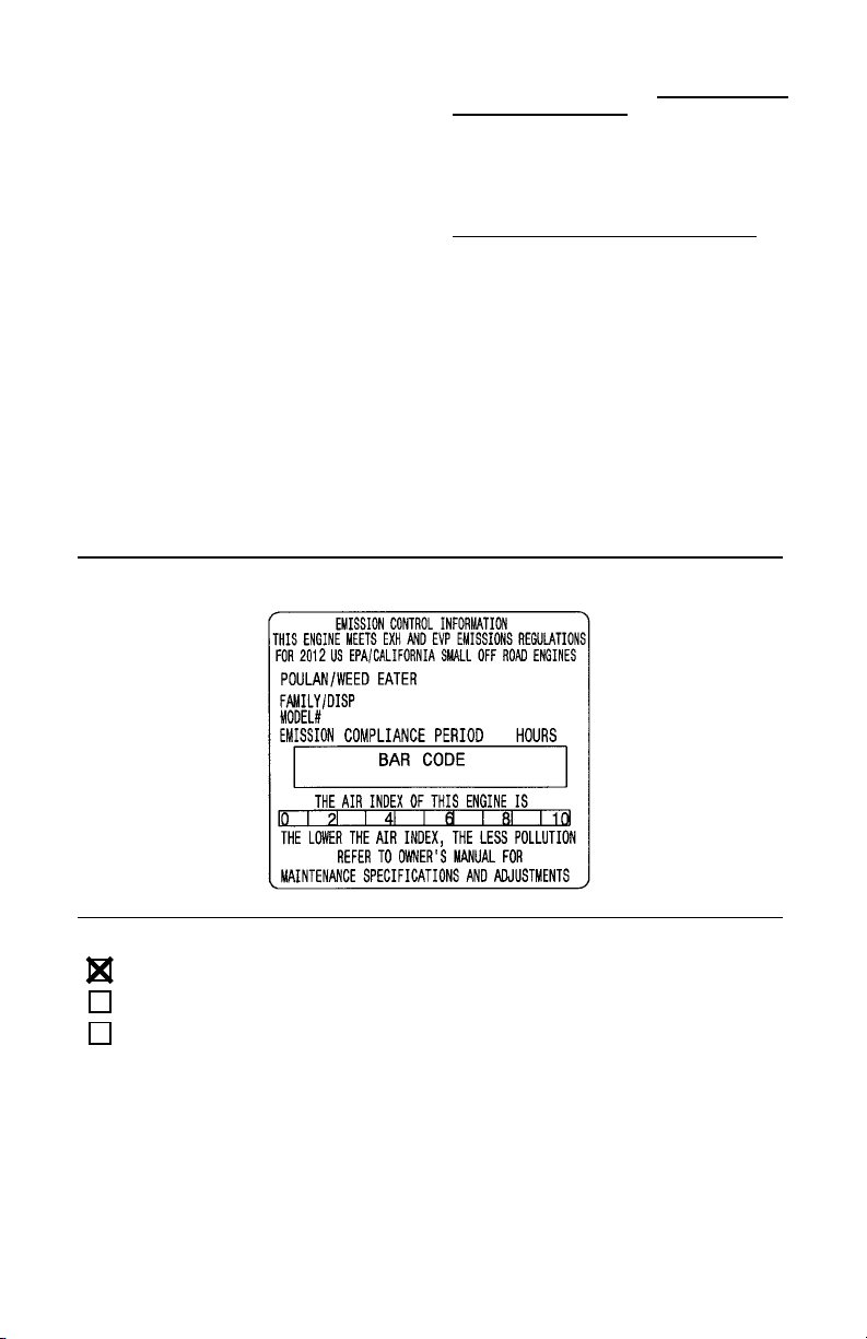
The information on the product label indicates which standard your engine is certified.
Example: (Year) EPA and/or CALIFORNIA.
center, call Husqvarna Consumer Outdoor
Products N.A., Inc., USA: 1--800--487--5951,
Canada: 1--800--805--5523, emission.warranty
@HCOP--emission.com. WHERE TO GET
WARRANTY SERVICE: Warranty services or
repairs shall be provided at all Husqvarna Consumer Outdoor Products N.A., Inc., service
centers. Call Husqvarna Consumer Outdoor
Products N.A., Inc., USA: 1--800--487--5951,
Canada: 1--800--805--5523,
emission.warranty@HCOP--emission.com.
MAINTENANCE, REPLACEMENT AND
REPAIR OF EMISSION RELATED PARTS:
Any HusqvarnaConsumer Outdoor Products
N.A., Inc., approved replacement part used in
the performance of any warranty maintenance or repair on emission related parts will
be provided without charge to the owner if the
part is under warranty. EMISSION CON-
TROL WARRANTY PARTS LIST: Carburetor, air filter (covered up to maintenance
schedule), ignition system: spark plug (covered up to maintenance schedule), ignition
module, muffler including catalyst (if
equipped), fuel tank, line, and cap. MAINTE-
NANCE STATEMENT: The owner is responsible for the performance of all required maintenance as defined in the instruction manual.
This engine is certified to be emissions compliant for the following use:
Moderate (50 hours)
Intermediate (125 hours)
Extended (300 hours)
16
IDENTIFICACIÓN DE LOS SÍMBOLOS DE SEGURIDAD
ADVERTENCIA:
descuidado o indebido de esta herramienta puede causar graves heridas.
ADVERTENCIA:
No seguir las instrucciones podía causar graves heridas tanto al operador
como a otras personas. Guarde el manual de instrucciones.
No permita que los niños usen este aparato.
¡Este aparato puede ser peligrosa! El uso
Lea el manual de instrucciones antes de usar.
La línea de corte arroja objetos violentamente. Los objetos arrojados pueden cegarlo o herirlo a usted y a terceros. Use
siempre anteojos de seguridad marcar con
Z87. Use siempre protección de oídos.
Se recomienda el uso de un casco,
pantalones pesados y largos, mangas
largas, botas y guantes.
Asegúrese de tener el cabello recogido
por encima de los hombros. No use
joyería, ropa suelta ni ropa con corbatas,
tiras, borlas, etc. que cuelgan libremente.
Pueden enredarse en las piezas en movimiento.
ADVERTENCIA:
cabezal de corte, la bobina especificada y la línea
de corte recomendado. Nunca use cuchillas ni
dispositivos desgrandores, alambre, soga, hilo, etc.
Este accesorio ha sido diseñado exclusivamente
como cortador a línea. El incumplimiento de cualquiera de las instrucciones puede causar graves
heridas.
Use exclusivamente la
ADVERTENCIA
Los gases de escape del motor de este producto
contienen sustancias químicas conocidas en el
Estado de California como causantes de cáncer,
defectos congénitos y otros daños reproductivos.
17

IDENTIFICACIÓN DE LOS SÍMBOLOS DE SEGURIDAD
Zona de peligro por objetos arrojados al aire.
S La línea de corte arroja objetos violentamente.
S Los objetos arrojados pueden cegarlo o herirlo a
usted y a terceros.
S Mantenga a personas y animales 15 metros (50 pies)
alejados de la zona de trabajo.
ADVERTENCIA:
almacene el combustible o utilice el aparato cerca de llamas o fuentes
de chispas (inclusive los cigarrillos, las llamas abiertas, y cualquier trabajo que cause chispas).
Paradetenerelmotor,empuje y sostengaelinterruptorSTOPen la posición
STOP hasta que el motor se haya detenido por completo.
La ubicación del tornillo de marcha lenta
Siempre apague el aparato y desconecte la bujía
antes de dar mantenimiento.
Al mantener este aparato, use solamente las
piezas de reemplazo idénticas.
Guarde el aparato al abrigo de la intemperie,
desenchufado, en un lugar alto, seco y fuera del alcance
de los niños.
Riesgo de incendios. Nunca mezcle, vierta, o
Utilice gasolina sin plomo y aceite para motores de dos tiempos
mezclado en proporción al 40:1 (2.5%).
18
IDENTIFICACIÓN DE LOS SÍMBOLOS DE SEGURIDAD
Symboles de arranque
Presione el bombeador 10 veces con firmeza (la primera presione moverá
el bombeador levemente, y se escuchara un sonido de “clic”).
Mientras mantiene el aparato en posición de arranque como se muestra,
tire del mango de la cuerda de arranque rápidamente hasta que
arranque el motor, pero no tire de la cuerda más de 10 veces.
REGLAS DE SEGURIDAD
ponibles). La protecciónpara los ojosdebe
ADVERTENCIA:
herramientadefuerzadejardinería, deberánobservarse precauciones básicas de seguirdaden
todomomentoparareducirel riesgo deincendio
y graves heridas. Lea y cumpla con todas las
instrucciones.
Cabe al usuario le responsabilidadde cumplir
con todas las advertencias e instrucciones.
¡Lea el manual de instrucciones en su totalidad antes de usar el aparato! Esté completamente familiarizadocon los controles y con el
uso correcto del aparato. Limite el uso de este
aparato a aquellas personas que hayan leído
y comprendido, y que vayan a obedecer, todas las advertencias e instrucciones tantoen
el aparato como en el manual. No permita
nunca a los niños que usen este aparato.
MANUAL DE
INSTRUCCIONES
ADVERTENCIA:
las nidispositivos desgranadores.El aparatofue
diseñado para ser usado exclusivamente como
cortadora línea.El usode cualquier otra piezao
accesorio incrementará el peligro de heridas.
Este aparato ha sido diseñado exclusivamente
como cortador a línea.
Siacontece algunasituación no previstaeneste
manual, tenga cuidado y use buen criterio. Si
necesita ayuda, entre en contacto con su
distribuidor autorizado del servicio o llame al
1-800-554-6723.
Al usar cualquier
INFORMACION
DE SEGURIDAD
DEL APARATO
Nunca use cuchil-
SEGURIDAD DEL USUARIO
S Vistase apropiadamente. Siempre use ante-
ojosde seguridado similarprotecciónparalos
ojos cuando use o dé mantenimiento a este
aparato (anteojos de seguridad están dis-
estar marcada Z87.
S Siempre utilize protección de oídos.
S Siempre utilize mascarilla para la cara o
mascarilla a prueba de polvo si se va a trabajar en condiciones donde hay polvo.
S Siempre utilize pantalones pesados y largos,
mangas largas, botas y guantes. Se recomienda el uso de pantorrilleras de seguridad.
S Siempre utilize protecciónparalos pies. No
trabaje descalzo ni en sandalias. Evite la
línea girante.
S Mantenga el cabello por encima de los hom-
bros, atándolo paratal efecto si es necesario.
Nouse ropasueltaniropa con corbatas,tiras,
borlas, etc. que cuelgan libremente. Pueden
enredarse en las piezas en movimiento.
S Si está completament tapado, estará más
protegido de los escombros y pedazos de
plantas tóxicos arrojados por la línea girante.
S Manténgasealerta. No hagauso del apara-
to estando cansado,enfermo,trastornadoo
bajola influenciadel alcohol, de drogas o de
remedios. Vigilebien lo que está haciendo;
use del sentido común.
S Nunca ponga el aparato en marcha ni lo
deje en marcha dentro de un recinto cerrado. Respirar los vapores del combustible lo
puede matar.
S Mantenga las manijas libres de aceite y de
combustible.
SEGURIDAD DEL APARATO Y EN
EL MANTENIMIENTO
S Desconectela bujía antesde hacer cualqui-
er mantenimiento menos los ajustes de la
marcha lenta.
S Inspeccione el aparato y cambie las piezas
dañadas o flojas antesde cadauso. Repare
toda fuga de combustible antes de usar el
aparato. Mantenga el aparato en buenas
condiciones de uso.
S Cambie todas las piezas del cabezal que
estén descantilladas, resquebrajadas,quebradas o dañadas de cualquier otro modo,
antes de usar el aparato.
19

S Haga el mantenimiento del aparato de
acuerdo a los procedimientos recomendados. Mantenga la línea de corte el largo
aprodiado.
S Use solamente línea de corte de la marca
WEED EATER recomendados. Nunca use
alambre, soga, hilo, etc.
S Instale la protector requerida antes de usar
su aparato. Use la bobina especificada.
Asegúrese que la bobina esté correctamente instalada y esté bien fijo.
S Asegúresequeelaparato estécorrectamente
armado como se muestra en el manual.
S Haga los ajustes de la marcha lenta con el
cabezal apoyado de modo que la línea no
pueda tocar nada.
S Mantenga alejadas a las demás personas
siempre que haga ajustes de la marcha
lenta.
S Use exclusivamente los accesorios y repues-
tos WEED EATER recomendados.
S Todo servicio y mantinimiento no explicado
eneste manualdeberá ser efectuadoporun
distribuidor autorizado del servicio.
SEGURIDAD CON EL COMBUSTIBLE
S Mezcle y vierta el combustible al aire libre.
S Manténgalo alejado de las chispas y de las
llamas.
S Use recipiente aprobado para el combus-
tible.
S No fume ni permita que se fume cerca del
combustible ni del aparato ni mientras éste
esté en uso.
S Evite derramar el combustible o el aceite.
Limpie todo el combustible derramado.
S Aléjese a por lo menos 3 metros (10 pies)
del lugar de abastecimiento antes de poner
en marcha el motor.
S Pareel motor y permitaque seenfríe elapa-
rato antes de retirar la tapa del tanque.
S Almacéne siempre combustible en un reci-
piente aprobado paralos líquidosinflamables.
S Repare toda fuga de combustible antes de
usar el aparato.
S Asegúrese de que la tapa del tanque de
combustibleestá bien apretado después de
agregar combustible.
SEGURIDAD AL CORTAR
ADVERTENCIA:
área antes de cada uso. Retire los objetos
(piedras, vidrio roto, clavos, alambre, etc.)
que se puedan enredar en la línea o que ésta
pueda arrojar. Los objetos duros pueden
dañarel cabezaly éste los puedearrojar,causando graves heridas.
S Mantengaa los niños,los espectadores y ani-
males a una distancia mínima de 15 metros
(50 pies). Se debe exhortar a los espectadores a que usen protección para los ojos.
Pare elmotor inmediatamente si alguien se le
acerca.
S Use el aparato exclusivamente para recortar,
para cortar césped y para barrer. No lo use
paracortarbordes,parapodar ni pararecortar
seto.
S Mantengael equilibrio, con los piesenunasu-
perficie estable. No se extienda demasiado.
Inspeccione el
S Mantengatodas laspartes delcuerpo aleja-
das de la línea girante y del silenciador.
Mantenga el motor por debajodelnivel dela
cintura. El silenciador puede causar graves
quemaduras cuando está caliente.
S Modelos W25CB, W25CF, W25CBK,
W25CFK: Corte siempre de derecha a
izquierda. Si se corta con la línea del lado
izquierdo del protector, los escombros volarán en sentido opuesto al usuario.
S Modelos W25SB, W25SF, W25SBK,
W25SFK: Corte siempre de izquierda a
derecha. Si se corta con la línea del lado
derecho del protector, los escombros volarán
en sentido opuesto al usuario.
S Use el aparato únicamente de día o en luz
artificial fuerte.
S Utilice el aparato solamente para las tareas
explicadas en este manual.
TRANSPORTE Y ALMACENAMIENTO
S Espere que el motor se enfríe y fije bien el
aparato antes de quardarlo o de transportarlo en un vehículo.
S Vacíeeltanquedecombustibleantesdeguar-
dar el aparato o de transportarlo. Consuma
todo el combustible restante en el carburador
poniendo el motor en marcha y dejándolo en
marcha hasta que le motor se pare solo.
S Guardeel aparato y el combustibleen un lu-
gar donde los vapores del combustible no
puedan alcanzar chispas ni llamas provenientes de los termotanques, los motores o
interruptores eléctricos, los calefactores
centrales, etc.
S Guarde el aparato de modoque el limitador
de línea no pueda causar heridas accidentales. Se puede colgar el aparato por la caja
el eje de propulsión.
S Guarde el aparato fuera del alcance de los
niños.
AVISO DE SEGURIDAD:
a las vibraciones a travésdelusoprolongadode
herramientas defuerza a gasolina puedecausar
daños a los vasos sanguíneoso alos nerviosde
los dedos, las manos y las coyunturasen aquellas personas que tienen propensidada los trastornos de la circulación o a las hinchazones
anormales. El uso prolongado en tiempo frío ha
sido asociado con daños a los vasos sanguíneos de personas que por otra parte se encuentranen perfectoestadodesalud. Si ocurren
síntomastalescomoelentumecimiento, eldolor,
lafaltade fuerza,loscambiosenel coloro latextura de lapielo faltade sentidoen los dedos, las
manos o las coyunturas, deje de usar esta
máquina inmediatamente y procure atención
médica. Los sistemas de anti--vibración no garantizan que se eviten tales problemas. Los
usuarios que hacen uso continuo y prolongando
de las herramientas de fuerza deben fiscalizar
atentamente su estado físico y el estado del
aparato.
AVISO ESPECIAL:
padacon silenciador limitador detemperatura
y con rejilla antichispa quecumpla losrequisitos de los Códigos de California 4442 y 4443.
Todas las tierras forestadas federales, más
los estados de California, Idaho, Maine, Minnesota,Nueva Jersey, Washington y Oregón,
El estarexpuesto
Su aparato viene equi-
20
requieren por ley que muchos motores de
combustióninterna estén equipados con rejilla antichispa. Si usted el aparato en un estado
y otralocalidaddondeexisten talesreglamentos, usted tiene la responsabilidad jurídica de
mantener estas piezas en correcto estado de
funcionamiento. De lo contrario, estará en in-
MONTAJE
fracción de la ley. Para el uso normal del
dueño de la casa, el silenciador y la rejilla
antichispa no requerirán ningún servicio.
Después de 50 horasde uso, recomendamos
que al silenciador se le de servicio o sea
substituido por un distribuidor autorizado del
servicio.
PRECAUCIÓN:
mado, repita todos los pasos para asegurar
que el mismo se encuentrecorrectamente armado y que todos los fijadores se encuentren
bien ajustados.
Examinelas piezaspara verificarqueno haya
daños. No use piezas dañadas.
AVISO:
si hay piezas dañadas, llame al número
1-800-554-6723.
Es normal escuchar que el filtro decombustible
golpetee en el tanque vacío.
Es normalencontrar residuos de aceiteo degasolina en el silenciador, debido a los ajustes al
carburador y a las pruebas efectuadas por el
fabricante.
Si necesita ayuda, si faltan piezas o
Si recibióel aparatoya ar-
MONTAJE DEL EJE
(Modelos W25CBK, W25CFK,
W25SBK, W25SFK)
PRECAUCIÓN:
coloqueel aparato sobre una superficieplana
para mantener la estabilidad.
1. Alinee los ranuras de los ejes superior y
inferior.
Eje Inferior
2. Presionelos dos ejesjuntos hastaque el eje
inferior se asienteporcompletoen el superior .
Cuandoensambles el eje,
Eje Superior
Ranuras
3. Deslice el conjunto inferior del manguito
de bloqueo sobre el superior y apriete girando en sentido horario.
Conjunto superior de
manguito de bloqueo
Conjunto inferior de
manguito de bloqueo
AVISO:
de bloqueo no esta apretado (el espacio es
más que 1/4 de pulgada), el eje superior y la
eje inferior no están completamente asentados.
Si el conjunto inferior del manguito
Espacio es más que 1/4 de pulgada
AJUSTE DEL MANGO
(Modelos W25CB, W25SB, W25CF,
W25SF)
PRECAUCIÓN:
auxiliar, asegúrese que éste se mantenga
sobre la etiqueta de seguridad y debajo la
marca o la flecha en el eje.
1. Afloje la tuerca mariposa en el mango.
2. Gire el mango enposición vertical.Vuelva
a apretar la tuerca mariposa firmemente.
Al ajustar la mango
AJUSTE DEL MANGO
(Modelos W25CBK, W25CFK,
W25SBK, W25SFK)
PRECAUCIÓN: Al ajustar la mango auxiliar,
asegúrese que éste se mantenga sobre el
conjunto superior de manguito de bloqueo y
debajo la marca o la flecha en el eje.
1. Afloje la tuerca mariposa en el mango.
2. Gire el mango enposición vertical.Vuelva
a apretar la tuerca mariposa firmemente.
21
INSTALACION DE LA PROTECTOR
PRECAUCIÓN:
instalado correctamente. El protector provee
protecciónparcial contra el riesgo de los objetos arrojados hacia el usuario y otras personas y viene equipado con un cuchilla limitadora de línea que corta el exceso de línea. El
cuchillalimitadorade línea(en la parte inferior
del protector) es filoso y puede cortar.
Para conseguir la orientación apropiada para el
protector, vea la ilustración CONOZCA SU
APARATO que se encuentra en la sección de
USO.
1. Remuevala tuercamariposade la protector.
2. Introduzca el soporte dentro de la ranura
como se muestra.
3. Haga girarla protectorhastaque eltornillo
pase a través del hueco en el soporte.
4. Apriete firmemente la tuerca mariposa en
el tornillo.
El protector deberá ser
Protector
Soporte
Ranura
Tuerca Mariposa
22
USO
CONOZCA SU APARATO
LEA ESTE MANUAL DE INSTRUCCIONES Y LAS REGLAS DE SEGURIDAD ANTES DE
PONER EL APARATO EN MARCHA. Compare las ilustraciones con su aparato para familiarizarse con la ubicación de los diversos controles y ajustes. Guardeeste manualpara uso futuro.
Modelos:
W25CB, W25CF,
W25CBK, W25CFK
Cabezal
de Corte
Cuchilla Limitadora de Línea
Modelos:
W25SB, W25SF,
W25SBK, W25SFK
Cabezal
de Corte
Cuchilla Limitadora de Línea
Eje
Protector
Eje
Protector
Modelos:
W25CBK, W25CFK,
W25SBK, W25SFK
Montaje para
Sujetar la
Manga
Interruptor
STOP
Mango de la
Cuerda de
Arranque
INTERRUPTOR STOP
Se usa el interruptor STOP para detener el motor. Paradetener elmotor, empujey sostenga el
interruptorenlaposiciónSTOP hastaque el motor se haya detenido por completo.
ANTES DE PONER EN MARCHA EL
MOTOR
ADVERTENCIA:
la información sobre el combustible en laas
reglasde seguridadantes decomenzar. Si no
comprende las reglas de seguridad, no
intente abastecer el aparato de combustible.
Llame al número 1-800-554-6723.
Lea atentamente
ABASTECIMIENTO DEL MOTOR
ADVERTENCIA:
del tanque de combustible lentamente al reabastecer combustible.
Remueva la tapa
Silenciador
Mango Auxiliar
Gatillo Acelerador
Bujía
Bombeador
Tapa del Tanque
de Mezcla de
Combustible
BOMBEADOR
El BOMBEADOR retira el aire de el carburador y de las líneas de combustible y las llena
demezcla decombustible, permitiéndoleponer el motor en marchacon menostirones dela
cuerda de arranque. Accione el bombeador
oprimiéndolo y luego dejando que este recobre su forma original.
INFORMACION UTIL
Para obtener la proporción
correcta de mezcla de
aceite vierta 3,2 onzas de
aceite sintético de 2 ciclos
dentro de gasolina fresca.
IMPORTANTE:
para operar con gasolina sin plomo con un
mínimo de octano 87 (método R+M/2), con
etanol mezclado hasta un 10% máximo por
volumen (E-10). Antes de la operación, la
gasolina se debe mezclar con un aceite para
motor enfriado por aire de 2 ciclos sintéticos de
Este equipo está diseñado
23
buena calidad diseñado para mezclarse a una
2.Mientras
mantiene
el
proporción de 40:1. Se recomienda el aceite
sintético de la marca Poulan/WEED EATER.
Mezcle la gasolina y el aceite a una proporción
de 40:1. Se obtiene una proporción de 40:1 al
mezclar 3,2 onzas líquidas (95 ml) de aceitecon
1 galón (4 litros)de gasolinasin plomo.NO USE
aceite automotriz ni aceite marítimo. Estos
aceites causarán daños al motor. Al mezclar
combustible, siga las instrucciones impresas en
elrecipiente. Unavez queel aceitese agreguea
la gasolina, agite el recipiente
momentáneamente para asegurar que el
combustible se mezcle bien. Siemprelea y siga
las reglas de seguridad relacionadas con el
combustible antes de llenar su unidad con
combustible. Compre combust- ible en
cantidades quese puedan usar en 30 díaspara
asegurar la frescura del combustible.
PRECAUCIÓN:
su unidad. Esto causará un daño permanente
en el motor y anulará la garantía limitada. No
usecombustibles alternativos como mezclas
de etanolpor arriba del 10%por volumen(E-15,
E-85) o cualquier combustible mezclado con
metanol. El uso de estos combustibles puede
causar un mayor desempeño del motor y
problemas de durabilidad.
Nunca use gasolina sola en
INFORMACION UTIL
Si su interruptor indica oprima para detener el motor,
este siempre se encuentra
en la posición ON.
POSICION DE
ARRANQUE
PARA ARRANCAR CON EL MOTOR
FRIO (o motor caliente después de
quedar sin combustible)
AVISO:
plana. NO apriete el gatillo del acelerador hasta
que arranqueel motor. Si elgatillo delacelerador
se apriete antes de que arranque el motor, el
motor no arrancara!
1. Presione el bombeador
Ponga el aparato en una superficie
10 veces con firmeza
(la primera presione
moverá el bombeador
levemente, y se escuchara
un sonido de “clic”).
Bombeador
PARA DETENER EL MOTOR
S Para detener el motor, em-
puje y sostenga el interruptor
STOP en la posición STOP
hasta que el motor se haya
detenido por completo.
PARA PONER EN MARCHA
EL MOTOR
ADVERTENCIA:
corte girará mientras seesté intentandoponer
en marchael motor. Evite el hacer ningún tipo
de contacto con el silenciador. Un silenciador
caliente podría provocar quemaduras de gravedad si se toca.
El cabezal de
INFORMACION UTIL
Si el motor de su aparato
no se pusiera en marcha
después de haber seguido
estas instrucciones, llame
al 1--800--554--6723.
Mango de la
Cuerda de
Arranque
Gatillo
Acelerador
aparato en posición de
arranque como se
muestra, tire del mango
de la cuerda de arranque
rápidamente hasta que
arranque el motor, pero
no tire de la cuerda más
de 10 veces.
24
3. Una vez que el motor arranca, permita que
Corte
izquierda
a
derecha.
marche por aproximadamente 30 segundos; luego, apriete el gatillo aceleradorpara
desactivar el sistema del arranque.
4. Si el aparato sin ponerse en marcha, proceda con la sección PARA ARRANCAR
CON EL MOTOR CALIENTE.
PARA ARRANCAR CON EL MOTOR
CALIENTE
1. Tire y suelteel gatilloaceleradorparaasegurarsede queel sistema dearranquefrío
ha sido desactivado.
2. Cuando el motor está caliente (operado
en los últimos 15 minutos), mantenga el
aparato en posición de arranque como
se muestra y tire del mango de la cuerda
de arranque rápidamente hasta que arranque el motor, pero no tire de la cuerda
más de 10 veces.
3. Si el aparato sin ponerse en marcha, proceda con la sección PARA ARRANCAR
CON MOTOR AHOGADO.
AVISO:
arrancar con el motor caliente puede ser utilizado dentro15 minutos despuésque el motor
se para. Si el aparato esta sin funcionar por
más de 15 minutos, será necesario arrancar
el aparato siguiendo los pasos abajo PARA
ARRANCAR CON MOTOR FRIO o después
trate los pasos de las instrucciónes de como
arrancar el aparato.
Normalmente, elprocedimiento para
PARA ARRANCAR CON EL MOTOR
AHOGADO
Oprima y sostengaelgatilloacelerador.Mantengaelgatillototalmenteoprimido hastaqueelmotor marche sin problemas. Tire firmemente del
mango de la cuerda de arranque hasta que el
motor arranque y se ponga en marcha. Esto
podrárequerirque se tire del mango de la cuerda muchas veces dependiendo cuan ahogado
se encuentre el motor. Si el aparato sigue sin
ponerse en marcha, vea la TABLA DIAGNOSTICA o llame al número 1-800-554-6723.
INSTRUCCIONES DE USO
Se recomienda que noopereel motor pormas
de un minuto a la velocidad máxima.
POSICIONES DE USO
Modelos W25CB, W25CF, W25CBK,
W25CFK:
USE SIEMPRE:
Protección
de oídos
El cabello
por encima
de los
hombros
Pantalones
Largos
Zapatos
Gruesos
Protección de
Ojos
Guantes
Corte derecha
a izquierda.
Modelos W25SB, W25SF,
W25SBK, W25SFK:
USE SIEMPRE:
Protección
de oídos
El cabello
por encima
de los
hombros
Pantalones
Largos
Zapatos
Gruesos
Protección de
Ojos
Guantes
ADVERTENCIA:
tección para los ojos. Nunca se incline por encima del cabezal. La línea puede arrojar o
hacer rebotar piedras o desechos hacia los
ojos y la cara, pudiendo causar la pérdida de
la vista u otras graves heridas.
Mantenga el equilibrio. Mantenga el aparato
con ambas manos con la mano derecha en el
mango trasero/gatillo acelerador y la mano
izquierda en el mango auxiliar. Mantenga
siempre el motor y el cabezalde corte por debajo del nivel de la cintura.
No haga marcharel motor a revolucionesmás
altas que las necesarias. La línea de corte
cortará de una forma más eficiente sin que el
motor esté acelerado a fondo. A revoluciones
más bajas, habrámenos ruido y menor vibración del motor. La línea de corte durará más
tiempo y tendrá menor probabilidad de “fundirse” en la bobina.
Use siempre pro-
25

Siempre que no se halle cortando, suelte el
La
puntadela
línea
La
línea
está
metida
gatilloacelerador y permita que el motor vuelva a marcha lenta.
Para detener el motor:
S Suelte el gatillo acelerador.
S Empuje y sostenga el interruptor STOP en la
posición STOP hasta que el motor se haya
detenido por completo.
AVANCE DE LA LÍNEA DE CORTE
(Modelos W25CB, W25SB, W25CBK,
W25SBK)
La línea de corte avanza aproximadamente 5
cm (2 pulgadas) cada vez que se toca el cabezal contra el suelo con el motor acelerado a
fondo. El largo más eficientede la líneaes ellargo máximo permitido por el limitador de línea.
Siempre mantenga la cubierta protectora en su
lugar siempre que el aparato esté en uso.
Para avanzar la línea:
S Acelere el motor a fondo.
S Sostenga el cabezal paraleloal suelo, por en-
cima de un área con césped.
S Toqueelcabezaldecortecontrael sueloleve-
mente una vez. Con cada toque, la línea
avanzará aproximadamente 5 cm (2 pulga-
das).
Toque el cabezal contra el suelo siempre en
un área con césped. Si se hace tocar contra
superficies como el cemento o el asfalto, el
cabezal podría sufrir desgaste excesivo.
Si la línea se ha gastado y cuenta con 5 cm (2
pulgadas) o menos, hará falta más de un toque
para obtener el largo de línea más eficiente.
ADVERTENCIA:
W25CB, W25SB, W25CBK, W25SBK, use
únicamente línea con diámetro de 2 mm (0,080
de pulgada). Las líneas de otros diámetros no
avanzarán debidamente y pueden causar
graves heridas. Para los modelos W25CF,
W25SF, W25CFK, W25SFK, use únicamente
un largo de línea de diámetro de 2,4 mm
(0,095 de pulgada) . No use otros materiales,
tales, como el alambre, el hilo, la cuerda, etc. El
alambre se puede quebrar al cortar, convirtiéndose enun proyectilmuy peligrosoy causando
heridas de gravedad.
Para los modelos
METODOS DE CORTE
ADVERTENCIA:
mínimay no acerque el aparato demasiado al
cortar cerca de objetos sólidos (piedra, gravilla, postes, etc.): estos pueden dañar el cabezal, pueden enredarse enla líneao la línealos
puedearrojarviolentamenteal aire, causando
serio peligro.
S Lapunta de la línea es la que corta. Se con-
seguirá mejor rendimiento y el mínimo des-
gaste si no se mete lalínea dentro del mate-
rial que se está cortando. La ilustración a
continuación muestra laformacorrecta ein-
correcta de cortar.
Use la velocidad
es la que corta.
Right
S Lalínearetirafâcilmenteelcéspedy las malas
hierbas de alrededor de paredes, cercados,
árboles y macizos de flores; pero también es
capaz de cortar la corteza tierna de árboles y
arbustos y de marcar las cercas. Para evitar
daños, especialmente a la vegetación delicada o a los árboles con corteza fina, acorte la
líneaa unos10a 13cm (4 a 5 pulgadas) yuse
el aparato sin acelerar a fondo.
S Para recortar o escalpar, use el aparatosin
acelerar a fondo, para incrementar la vida
útilde la líneay disminuir el desgastedelcabezal, especialmente:
S Al hacer trabajos livianos.
S Cerca de objetos con los cuales la línea se
puede enredar, como son los postes o
árboles de poco diámetro y el alambre de
las cercas.
S Para cortar césped y barrer, acelere el mo-
tor a fondo para lograr un buen trabajo de
limpieza.
PARA RECORTAR -- Sostenga el cabezal
unos 8 cm (3 pulgadas) del suelo y en ángulo.
Unicamente la punta de la línea deberá hacerel
contacto con el material a cortar. No meta la
línea dentro del área que se está cortando.
Para Recortar
PARAESCALPAR-- Latécnica del ascalpado
retirala vegetaciónno deseada abajo a la tierra. Sostenga el cabezal unos 8 cm (3 pulgadas) del suelo y en ángulo. Deje que la punta
de la línea golpeecontra el suelocerca de los
árboles, los postes, los monumentos, etc.
Esta técnica incrementa el desgaste de la
línea.
dentro del material
de trabajo.
Wrong
8 cm (3 pulgadas) del suelo
26

Para Escalpar
PARA CORTAR CESPED -- Este parato es
idealpara cortar césped en lugares donde las
cortadoras convencionales no llegan. En posición de cortar césped,mantengala línea paralelaal suelo.Evite presionar el cabezal contra el suelo, ya que de hacerlopodríaescalpar
la vegetación y dañar el aparato.
Para Cortar Césped
MANTENIMIENTO
ADVERTENCIA:
bujía antes de hacer cualquier mantenimiento,
con la excepción de los ajustes de la marcha
lenta.
INFORMACION UTIL
IMPORTANTE:
que toda reparación que no
sea el mantenimiento recomendado en el manual
de instrucciones sea efectuada por un distribuidor
Si un distribuidor NO autorizado efectuara cualquier trabajo en el producto,
WEED EATER no pagará reparaciones
bajo la garantía. Es su responsabilidad el
mantener y efectuar el mantenimiento
general del producto.
VERIFIQUE QUE NO HAYA FIJADORES NI PIEZAS SUELTAS
S Cubierta de la Bujía
S Filtro de Aire
S Tornillos de la Caja
S Tornillo del Mango Auxiliar
S Protector
S Tapa del Tanque
VERIFIQUE QUE NO HAYA PIEZAS
DAÑADAS O GASTADAS
Entre en contacto con el distribuidor autorizado del servicio para el reemplazo de piezas
dañadas o desgastadas.
S InterruptorSTOP-- Asegúrese de queel inter-
ruptor STOP esté funcionandocorrectamente
autorizado del servicio.
Desconecte la
Permita
PARA BARRER -- Se puede usar la acción
ventiladora de lalínea girante para barrerrápida y fácilmenteun áreadeterminada.Mantengala línea paralelaal suelodirectamenteencima de las superficies que se quiera barrer y
meuva el aparato de un lado al otro rápidamente.
Para Barrer
empujando y sosteniendo el interruptor en la
posiciónSTOP. Asegúresede queel motorse
haya detenido por completo. Ponga el motor
en marcha nuevamente y continúe.
S Tanque de Combustible -- Deje de usar el
aparatosi hay señales dedaños o pérididas
en el tanque de combustible, la tapa de
tanque, y/o el líneas de combustible.
S Protector-- Deje de usar el aparato si elpro-
tector está dañado.
INSPECCIONE Y LIMPIE EL APARATO Y SUS PLACAS
S Después de que cada uso, inspeccione la
aparato completa para saber si hay piezas
flojas o dañadas. Limpie el aparato y las
placas usandoun trapo húmedo con un de-
tergente suave.
S Seque el aparato usando un trapo seco y
limpio.
LIMPIE EL FILTRO DEL AIRE
Los filtros de aire sucios disminuyen la vida
útily el rendimientodel motore incrementanel
consumodecombustibley deemicionesnocivas. Limpie siempre el filtro de aire después
de cada 5 horas de uso.
1. Limpie latapa del filtrode aire y el área al-
rededor de la tapa para evitar que caiga
suciedad o desechos en el carburador
cuando se abre la tapa.
2. Abra latapa del filtro de aire presionando el
botón(vea la ilustración). Remueva el filtro.
AVISO:
emiciones evaporativas nocivas, no limpie el
filtro de aire con gasolina nicualquier otro solvente inflamable.
3. Limpie el filtro con agua y jabón.
Para evitar peligro de incendio y de
27

4. Permita que el filtro se seque.
Introduzca
la
línea
5. Instale el filtro de aire y cierra la tapa.
Botón
Filtro de
Aire
Tapa del Filtro de Aire
SILENCIADOR Y LA REJILLA ANTICHISPAS
A medida que se use el aparato,el silenciador
y la rejilla antichispas se van carbonizando.
Para el uso normal del dueño de la casa, sin
embargo, el silenciador y la rejilla antichispa no
requerirán ningún servicio. Después de 50
SERVICIO Y AJUSTES
horasde uso,recomendamos que al silenciador
se le de servicio o sea substituido por un distribuidor autorizado del servicio.
CAMBIE LA BUJIA
Deberá cambiarse la bujía anualmente para
asegurar que el motor arranque fácilmente y
tenga un mejor rendimeinto.Ajuste la separación de los electrodos a 0,6 mm (0,025 de pulgada). El encendido es fijo e inalterable.
AVISO:
nadienses: Este sistema de ignición cumple
con los requisitos del estándar Canadiense
ICES--002.
1. Gire y saque la cubierta de la bujía.
2. Retire la bujía del cilindro y deséchela.
3. Por solamente modelos de Estados
4. Ajuste firmemente la bujía nueva con una
5. Instale nuevamentela cubiertade labujía.
Por solamente modelos Ca-
Unidos: Cámbiela por una bujía Champion
RCJ-6Y.
Por solamente modelos Canadienses:
Cámbiela por una bujía Champion QCJ-6Y.
llave de cubo de 19 mm (3/4 de pulgada).
REEMPLAZO DE LA LINEA
(Modelos W25CB, W25SB, W25CBK,
W25SBK)
ADVERTENCIA:
W25CB, W25SB, W25CBK, W25SBK, use
únicamente línea con diámetro de 2 mm (0,080
de pulgada). Las líneas de otros diámetros no
avanzarán debidamente y pueden causar
graves heridas. Para los modelos W25CF,
W25SF, W25CFK, W25SFK, use únicamente
un largo de línea de diámetro de 2,4 mm
(0,095 de pulgada) . No use otros materiales,
tales, como el alambre, el hilo, la cuerda, etc. El
alambre se puede quebrar al cortar, convirtiéndose enun proyectilmuy peligrosoy causando
heridas de gravedad.
1. Retire labobinatirandodel botónde toque
firmemente.
2. Limpie por entero la superficie del cubo y
de la bobina.
3. Reemplace la bobina por una previamente enrollada, o corte dos pedazos de
aproximadamente 3,8 metros (12-1/2
pies) de largo de línea de 2 mm (0,080 de
pulgada) de la marca WEED EATER.
4. Introduzca las puntas de la línea, alrededor de 1 cm (1/2 pulgada), dentro del huecos pequeño que se encuentraen laparte
interior de la bobina.
Bobina
Para los modelos
Huecos
Pequeño
dentro de la muesca
Hueco de
Cubo
Introduzca
la línea
dentro de la
muesca
Hueco de salida
de la línea
5. Enrollela línea en labobinade forma pareja y ajustada. Enrolle la línea en la direcciónen que apuntanlas flechasque seencuentran en la bobina.
6. Introduzca la líneadentrode las muescas,
dejando de 7 a 12 cm (3 a 5 pulgadas) sin
enrollar.
7. Introduzca la líneas dentro de los huecos
de salida en el cubo como se muestra en
la ilustración.
8. Alínee las muescas con el los huecos de
salida de la línea.
9. Presione la bobina dentro del cubo hasta
que ésta encaje en su lugar.
10. Tire de la líneas que se extiende fuera del
cubo para soltarla de la muescas.
salida de la
línea
28

REEMPLAZO DE LA LINEA
(Modelos W25CF, W25SF, W25CFK,
W25SFK)
ADVERTENCIA:
W25CB, W25SB, W25CBK, W25SBK, use
únicamente línea con diámetro de 2 mm (0,080
de pulgada). Las líneas de otros diámetros no
avanzarán debidamente y pueden causar
graves heridas. Para los modelos W25CF,
W25SF, W25CFK, W25SFK, use únicamente
un largo de línea de diámetro de 2,4 mm
(0,095 de pulgada) . No use otros materiales,
tales, como el alambre, el hilo, la cuerda, etc. El
alambre se puede quebrar al cortar, convirtiéndose enun proyectilmuy peligrosoy causando
heridas de gravedad.
Para que elaparato funcione de maneraapropiada,la línea decorte deberáser reemplazada cuando ésta se encuentre desgastadacon
menos de 7 1/2 cm (3 pulgadas) de longitud
comenzandodesdeel bordede los túneles de
posición a cada lado del cabezal de corte.
1. Retire y desechela línea gastada antesde
instalar la línea nueva.
2. Limpie toda la superficie del cabezal de
corte.
3. Inserte los extremos de la líneaen los dos
orificios de guía de la parte delantera del
cabezal de corte.
Para los modelos
5. Tire de los extremos de la línea hasta que
esté tirante. Una línea correctamente
instaladatendrá la misma longitud en ambos extremos.
REEMPLAZO DE LA CABEZAL DE
CORTE (Modelos W25CB, W25SB,
W25CBK, W25SBK)
1. Sostenga la taza para el polvo con una
llave. Esto previene que el eje gire
mientras usted remueva y instale el
cabezal de corte.
Taza para
el polvo
2. Remueva el cabezalde corte dando vuelta a la izquierda (mirando desde la base
del aparato).
3. Enrosque el cabezal de remplazo en el eje
dando vuelta a la derecha. Apriete firmemente.
REEMPLAZO DE LA CABEZAL DE
CORTE (Modelos W25CF, W25SF,
W25CFK, W25SFK)
1. Haga girarel tazapara elpolvopara hacer
coincidirel orificiocon elotro orificiosituado a un lado del cajetín de engranajes.
2. Introduzca un destornillador pequeño por
los orificios confrontados. Esto previene
que el eje gire mientras usted remueva y
instale el cabezal de corte.
Orificio de
Guía
Orificio de
Guía
4. Continúe alimentando la líneaa través de
los orificios de guía hastaque se extienda
completamente a través de los orificios
laterales de salida.
Orificio lateral
de salida
Orificio lateral
de salida
Destornillador
3. Sujete el destornillador en su posición y
remueva el cabezal de corte dando vuelta a
la derecha (mirando desde la base del
aparato).
4. Enrosque elcabezalde remplazo en eleje
dando vuelta a la izquierda. Apriete
firmemente.
5. Remueva el destornillador.
AJUSTE DE LA MARCHA
LENTA
ADVERTENCIA:
personasalejadasde lazona endonde se encuentre haciendo ajustes de marcha lenta. El
cabezal de corte se mantendrá girando durante este procedimiento. Use su equipo protector y observe todas las precauciones de
seguridad.
El carburador ha sido ajustado cuidadosamente en la fábrica. Posiblemente sea necesario hacer ajustes demarcha lentasi se nota
cualquiera de las siguientes condiciones:
Mantenga a otras
29

S El motor no funcionaen marchalenta cuan-
T
ornillo
de
Ajuste
de
do se suelta el acelerador.
Haga los ajustes sosteniendo el equipo de
manera que el accesorio de corte se encuentre alejado del suelo y no haga contacto
con ningúnobjeto. Sostenga el aparatomanualmente mientras el motor se encuentre encendido y mientras usted se encuentre haciendolosajustes. Mantengatodas las partes
de su cuerpo alejadas de los accesorios de
corte y del silenciador.
Para ajuste de la marcha lenta:
Arranque el motor y deje que se caliente por
4--5 minutos durante el corte pesado, o por
10--15 minutos durante el corte moderado.
Deje el motor en marcha lenta. Ajuste las revoluciones hasta que el motor se mantenga
en marchasin calarse (la marchalenta es demasiado lenta).
S Gire el tornillo de marcha lenta hacia la dere-
cha para aumentar las revoluciones si el mo-
tor se ahoga o se para.
S Gire el tornillo de marcha lenta hacia la iz-
quierda para reducir las revoluciones.
ALMACENAJE
la Marcha Lenta
Si requiriera ayuda adicional o no se sintiera
seguro al desempeñar este procedimiento,
entre en contacto con el distribuidor autorizado del servicio o llame al 1--800--554--6723.
PRECAUCIÓN:
pasos después de cada uso:
S Permita que el motor se enfríe y fije bien el
aparato antes de guardarlo o transportarlo.
S Guardeel aparato y el combustibleen un lu-
gar bien ventilado donde los vapores del
combustible no puedan entrar en contacto
con chispas ni llamas abiertas provenientes
de clentadores de agua,motores ointerrup-
tores eléctricos, calefactorescentrales,etc.
S Guardeel aparato contodos losprotectores
ensu lugary coloquelode modoque laspie-
zas cortantesnopuedancausar heridas por
accidente.
S Guardeel aparato y el combustibleen un lu-
gar completamentefuera delalcance delos
niños.
Realice los siguientes
ESTACIONAL ALMACENAJE
Prepare el aparato para almacenarlo al final
dela temporadao si no lo va a usar por másde
30 días.
Si va a almacenarel aparato durante unperiodo largo de tiempo:
S Limpie el aparato por completo antes del al-
macenaje.
S Almacene en un área limpia y seca.
S Aplique una pequeña cantidad de aceite a
las superficies externas metálicas.
SISTEMA DE COMBUSTIBLE
Vea el mensaje marcado como IMPORTANTE, que se refiere al uso de combustible
adecuado en su motor en su aparato, en la
sección de USO, bajo ABASTECIMIENTO
DEL MOTOR. Los estabilizadores de combustible son una alternativa aceptable para
minimizar la formación de depósitos de goma
durante el almacenaje.
Añadaestabilizadora la gasolina en el tanque
de combustible o en el recipiente para almacenar el mismo. Siga las instrucciones de
mezcla quese encuentran impresas en el envase. Ponga el motor en marcha y déjelo en
marcha por unos 5 minutos después de haberle puesto estabilizador.
INFORMACION UTIL
Si almacenara su mezcla de
gasolina y aceite, con el
tiempo,elaceitese separará
de la gasolina.
Recomendamos agite el recipiente cada semana para
asegurarse de que la mezcla de gasolina y aceite sea
la apropiada.
INTERIOR DEL MOTOR
S Retire la bujía y vierta una cucharadita de
aceite 40:1 para motores a 2 tiempos (enfriados a aire) por la abertura para la bujía.
Lentamente, tire de la cuerda de arranque
de 8 a 10 veces para distribuir el aceite.
S Cambie la bujía por una nueva del tipo y de
la gama de calor recomendados.
S Limpie el filtro de aire.
S Examine todo el aparato para verificar que
no haya tornillos, tuercas ni pernos sueltos.
Cambie todas la piezas dañadas, quebradas o gastadas.
S Al principio de la próxima temporada, use
exclusivamente combustible fresco con la
proporción correcta de gasolina a aceite.
OTROS
S No guarde la gasolina de una temporada a
la próxima.
S Cambie el recipiente de gasolina si se em-
pieza a oxidar.
30

T
ABLA
DIAGNOSTICA
ADVERTENCIA:
er cualquiera de las reparaciones recomendadas acontinuaciónque no requieran que
la unidad esté en operación.
SINTOMA CAUSA SOLUCION
El motor no
arranca.
El motor no
anda en
marcha lenta
como debe.
El motor no
acelera, le
falta
potencia o
se para bajo
carga.
El motor
humea excesivamente
El motor
marcha con
temperatura
elevada.
1. El motor está ahogado.
2. El tanque de combustible
3. La bujía no está haciendo
4. El combustible no está
5. El carburador requier
1. El carburador requier
2. Las lunas del cigueñal
3. La compresión está baja.
1. El filtro de aire está sucio.
2. La bujía está carbonizada.
3. El carburador requiere
4. Acumulación de carbón.
5. La compresión está baja.
1. La mezcla de combustible
2. El filtro de aire está sucio.
3. El carburador requiere
1. La mezcla de combustible
2. Se ha instalado la bujía
3. El carburador requiere
4. Acumulación de carbón.
Siempreapagueel aparato y desconecte la bujíaantes dehac-
1. Vea “Arranque de Motor Ahogado”
en la sección Uso.
está vacío.
chispa.
llegando al carburador.
ajuste.
ajuste.
están gastadas.
ajuste.
se ha hecho incorrecta-mente.
ajuste.
está se he hecho
incorrectamente.
incorrecta.
ajuste.
2. Llene el tanque con la mezcla
correcta de combustible.
3. Instale una bujía nueva.
4. Verifique si el filtro de combustible no
esté sucio; cámbielo. Verifique si hay
dobleces en la línea de combustible
o si está partida; repárela o cámbiela.
5. Entre en contacto con el distribuidor
autorizado del servicio.
1. Vea “Ajuste de la Marcha Lenta del Carburador” en la sección Servicio y Ajustes.
2. Entre en contacto con el distribuidor
autorizado del servicio.
3. Entre en contacto con el distribuidor
autorizado del servicio.
1. Limpie o cambie el filtro de aire.
2. Limpie o cambie la bujía y calibre
la separación.
3. Entre en contacto con el distribuidor
autorizado del servicio.
4. Entre en contacto con el distribuidor
autorizado del servicio.
5. Entre en contacto con el distribuidor
autorizado del servicio.
1. Vacié el tanque de combustible y
llénelo de combustible con la mezcla
correcta.
2. Limpie o cambie el filtro de aire.
3. Entre en contacto con el distribuidor
autorizado del servicio.
1. Vea “Abastecimiento del Motor” en la
sección Uso.
2. Cambie por la bujía correcta.
3. Entre en contacto con el distribuidor
autorizado del servicio.
4. Entre en contacto con el distribuidor
autorizado del servicio.
31

GARANTIA LIMITADA
WEED EATER, una división de Husqvarna
Consumer Outdoor Products N.A., Inc., garantiza al comprador original que cada nuevaherramientacon funcionamiento a gasolinao accesorio de la marca WEED EATER está libre de
defectosen el materialy manode obray estáde
acuerdo en reparar o reemplazar, bajo esta garantía, cualquier producto con funcionamiento a
gasolinao accesoriodeacuerdocon lo siguiente
a partir de la fecha original de compra:
2AÑOS -- Piezas ymanode obra, cuandosea
de uso doméstico.
90 DÍAS -- Piezas y mano deobra, cuando sea
de uso comercial, profesional o con fines de
lucro.
30 DÍAS -- Piezas y mano de obra,cuando se
utilice para rentarlo.
Esta garantía no es transferible y no cubre los
daños o responsabilidades provocadas por el
manejoinapropiado, mantenimiento inapropiado
o alteración, o por el uso de accesorios y/o
componentes adicionales no recomendados
específicamente por WEED EATER para esta
herramienta. Esta garantía no cubre afinación,
bujías de encendido, filtros, cuerdas de
arranque,resortes de arranque,líneade corte, o
partes giratorias de la cabeza que sufran
desgaste y requieran reemplazarse con el uso
razonable durante el período de garantía. Esta
garantía nocubre ajustes previos a la entrega o
ajustes normales explicados en el instructivo de
uso. Esta garantía no cubre costos de
transportación.
En el caso deque tengaunareclamaciónbajo
esta garantía, deberá devolver el producto a
un distribuidor autorizado del servicio.
En caso de duda con respecto a esta garantía, por favor contacte a:
WEED EATER, una división de Husqvarna
Consumer Outdoor Products N.A., Inc.
9335 Harris Corners Parkway
Charlotte, NC 28269
1--800--554--6723
Contacto en Canadá:
WEED EATER
850 Matheson Blvd. West
Mississauga, Ontario L5V 0B4
Dandoel númerodelmodelo, el númerodeserie
y lafechade la comprade su producto así como
elnombre y la direccióndeldistribuidor autorizado de quien fue comprada.
ESTA GARANTÍA LE OTORGA DERECHOS
ESPECÍFICOS LEGALES Y PODRÍA TENER
OTROS DERECHOSQUE VARÍANEN CADA
ESTADO.
NO SE PERMITEN RECLAMACIONES POR
DAÑOS CONSECUENCIALES O
DERIVADOS, Y NO EXISTEN OTRAS
GARANTÍAS EXPRESAS EXCEPTO LAS
EXPRESAMENTE ESTIPULADAS EN
ESTE INSTRUMENTO.
ALGUNOS ESTADOS NO PERMITEN LAS
LIMITACIONES SOBRE LA DURACIÓN DE
UNA GARANTÍA IMPLÍCITA O SOBRE LAS
EXCLUSIONES O LIMITACIONES DE
DAÑOS CONSECUENCIALES O
INCIDENTALES, DE MODO QUE LAS
LIMITACIONES ANTERIORES PODRÍAN
NO SER APLICABLES EN SU CASO.
Ésta es una garantía limitada dentro del significado del término tal como se define en la Ley
Magnuson Moss de 1975.
La política de WEED EATER es la demejorar
continuamente sus productos. Por ello,
WEED EATER se reserva el derecho a
cambiar, modificar o descontinuar la
fabricación de modelos, diseños,
especificaciones y accesorios de todos los
productos, en cualquier momento sin previo
aviso ni obligación para el comprador.
32

IMPORTANTE:
Ambiental de los Estados Unidos (EPA) referente a emisiones de escape y evaporación. Para
asegurar laconformidad con EPA Fase 3, se recomiendautilizar sólorepuestos originalesde lamarca WEED EATER. El uso de otro tipo de repuestos incumple las leyes federales.
Esteproductoes conforme con la normativaFase3 dela Agenciade Protección
DECLARACION DE GARANTIA DE CONTROL
DE EMISION DE U.S. EPA/CALIFORNIA/
AGENCIA AMBIENTAL CANADIENSE
SUS DERECHOS Y OBLIGACIONES DE
GARANTIA: La Agencia de Protección Am-
bientalde los Estados Unidos, laJunta deRecursos Ambientales de California, la Agencia
Ambiental Canadiense y Husqvarna Consumer Outdoor Products N.A., Inc., se complacenenexplicarla garantía conla que cuenta el sistema de control de emisión en su
motorpequeño,modelo2012 y más adelante,
para uso fuera de carretera. En California, todos los motores pequeños para uso fuera de
carretera deben ser diseñados, construídosy
equipados para satisfacer las rigurosas normas antihumo que posee el estado.
Husqvarna Consumer Outdoor Products
N.A., Inc., deberá garantizar el sistema de
control de emisión en su máquina de motor
pequeño para uso fuera de carretera por los
períodos de tiempo que explicamos a continuacióny con la condiciónde quesu máquina
de motor pequeño para uso fuera decarretera
no haya sufrido ningún tipo de abuso, negligencia o mantenimiento inapropiado. Su sistema de control de emisión incluye piezas
tales como el carburador, el sistema de ignición y el tanquede combustible,línea de combustible, y tapa. Donde exista una condición
que requiera reparación bajo garantía,
Husqvarna Consumer Outdoor Products
N.A., Inc., reparará gratis su motor pequeño
parauso fuerade carretera. Los gatos cubiertos bajo la garantía incluyen el diagnóstico,
las piezas y labor. CUBIERTA DE GARAN-
TIA DEL FABRICANTE: Si cualquier pieza
relacionada con el sistema de emisión de su
motor (como hemos enumerado en la lista de
piezas de controlde emisiónbajogarantía)se
encontraradefectuosa o defectos en el material o en la labor del motor causaran que tal
piezacomenzaraa fallar,la pieza seráreparada o reemplazada por Husqvarna Consumer
Outdoor Products N.A., Inc. GARANTIA DE
RESPONSABILIDAD DE DEL DUEÑO:
Como dueño de una máquina de motor pequeñopara uso fuera de carretera, usted será
responsable por el mantenimiento adecuado
en los períodos previamente programados y
enumerados en su manual de instrucciones.
Husqvarna Consumer Outdoor Products
N.A., Inc., recomienda que guarde todos los
recibosqueindiquenquese hadesempeñado
mantenimiento en su máquina de motor pequeño para uso fuera de carretera, pero
Husqvarna Consumer Outdoor Products
N.A., Inc., no podrá negar el servicio bajo garantía únicamente a causa de la falta de recibos o por el incumplimiento de su parte en
asegurarse que el mantenimiento programado haya sido desempeñado. Como dueño de
una máquina de motor pequeño para uso
fuerade carretera, usted deberácontar con el
conocimiento de que Husqvarna Consumer
Outdoor Products N.A., Inc., puede negar la
cubierta bajo garantíasi su máquinade motor
pequeño para uso fuera de carretera o alguna
pieza de la misma ha dejado de funcionar debido al abuso, negligencia, mantenimiento inapropiado, modificaciones no aprobadas o el
uso de piezas que no hayan sido fabricadas o
aprobadas por el fabricante original del equipo. Es responsabilidad suya el llevar su
máquina de motor pequeñopara uso fuerade
carretera a un centro de reparación autorizado Husqvarna Consumer Outdoor Products
N.A., Inc., tan prontocomo se presente elproblema. Las reparaciones bajo garantía deberán ser completadas en un período de tiempo razonable, que no exceda los 30 días. Si
cuenta usted con algunapreguntaen relación
a sus derechos y responsabilidades de garantía,usted deberácomunicarsecon sucentrode servicioautorizadomás cercano,llamar
a Husqvarna ConsumerOutdoor ProductsN.A.,
Inc., en USA: 1--800--487--5951, en Canadá:
1--800--805--5523, emission.warranty@HCOP-emission.com. FECHA DEL COMIENZA DE
LA GARANTIA: El período de garantía comienza en la fecha decompra de la máquinade
motor pequeño para uso fuera de carretera.
DURACION DE LA GARANTIA: Esta garantía cuenta con un período de duración de
dos años comenzando en la fecha inicial de
compra, o hasta el final del garantía de producto (cualquiera que sea más largo). QUE
CUBRE LA GARANTIA: REPARACION O
REEMPLAZO DE PIEZAS. La reparación o el
reemplazode cualquier pieza garantizadaserán
desempeñados y ofrecidos al dueño sin costo
algunoenuncentrodeservicioHusqvarnaConsumer Outdoor Products N.A., Inc. Si cuenta
usted con alguna pregunta en relación a sus
derechos y responsabilidades de garantía,
usteddeberácomunicarsecon su centro de servicio autorizado más cercano, llamar a
Husqvarna Consumer Outdoor Products N.A.,
Inc., en USA: 1--800--487--5951, en Canadá:
1--800--805--5523, emission.warranty@HCOP-emission.com.PERIODO DE GARANTIA: Cu-
alquier piezagarantizadaquenoestéprogramada para ser reemplazada como parte del mantenimiento requerido, o que esté programada
únicamente para inspección regular para efectos de “reparación o reemplazo si fuera necesario” deberá garantizarse por un período de dos
años.Cualquierpieza garantizadaqueestéprogramada para ser reemplazada como parte del
mantenimiento requerido deberá estar garantizada por elperíodo de tiempo que comienza en
la fecha de compra inicial hasta la fecha del
primer reemplazoprogramado paradichapieza.
33
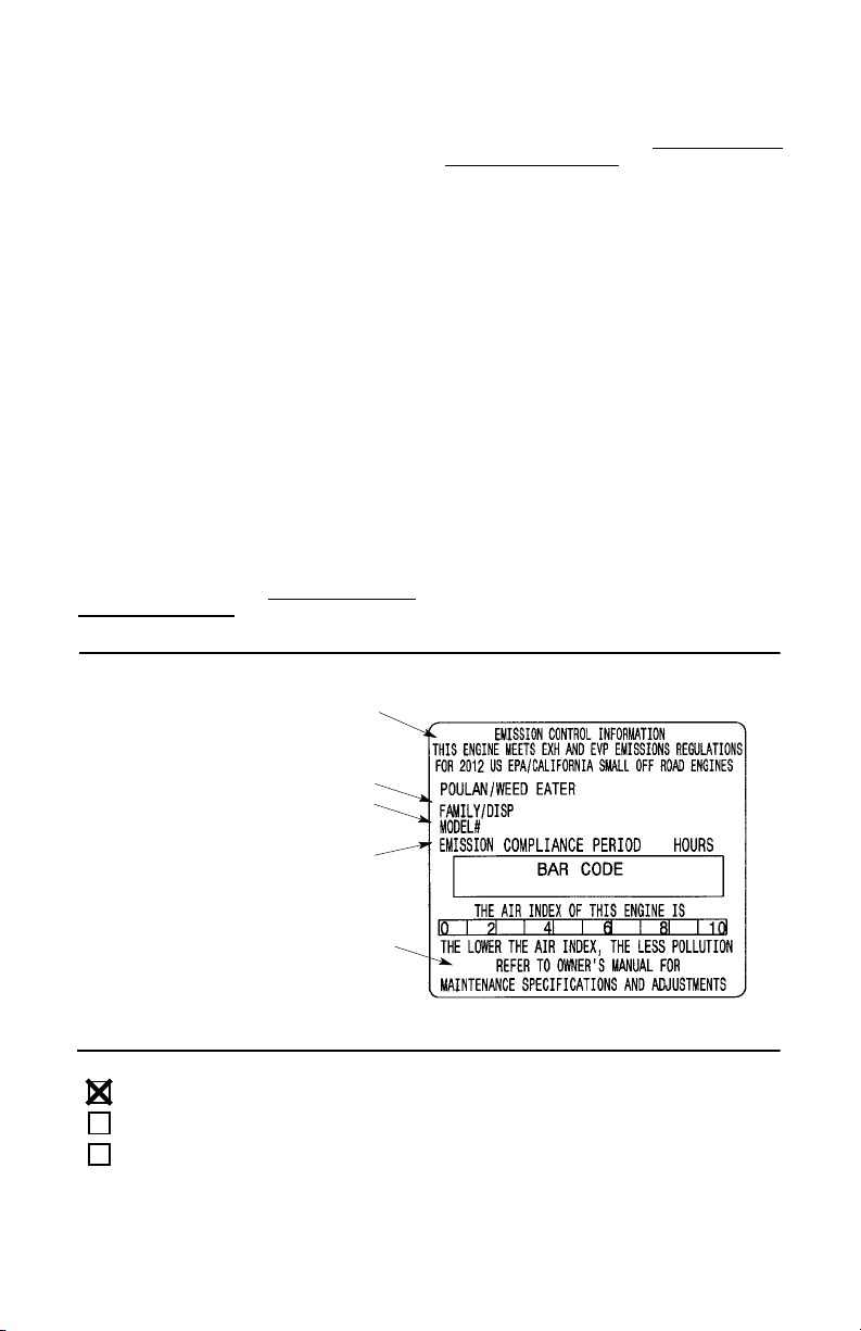
DIAGNOSTICO: No se deberá cobrar aldueño
ningúntipo de cargos por la labor de diagnóstico
la cual determine que una pieza garantizada se
encuentra defectuosa si el trabajo de diagnóstico ha sidodesempeñadoporuncentrodeservicio autorizado Husqvarna Consumer Outdoor
Products N.A., Inc. DANOS POR CONSE-
CUECIA: Husqvarna Consumer Outdoor
Products N.A., Inc., podrá ser responsable de
daños ocurridos a otras piezas delmotorcausados porla falla deuna pieza garantizada que se
encuentre bajoel períodode garantía.QUE NO
CUBRE LA GARANTIA: Todas las fallas causadas por elabuso, negligencia o mantenimiento inapropiado no están cubiertas. PIEZAS
AÑADIDAS O MODIFICADAS: El uso de piezasañadidaso lamodificaciónde piezaspodrán
servir como base paraque se anulela reclamación de garantía. La garantía de Husqvarna
Consumer Outdoor Products N.A., Inc., no se
responsabilizaporel mal funcionamiento debido
al uso de piezas añadidas o de piezas modificadas. COMO ENTABLAR UNA RECLAMA-
CION: Si cuenta usted con alguna pregunta relacionada con sus derechos y
responsabilidades de garantía, usted deberá
entrar encontacto consu centrode servicioautorizado Husqvarna Consumer Outdoor
Products N.A., Inc., más cercano, llamar a
Husqvarna Consumer Outdoor Products N.A.,
Inc., en USA: 1--800--487--5951, en Canadá:
1--800--805--5523, emission.warranty@
HCOP--emission.com.
La información en la etiqueta del producto indica las normas de certificación de su motor.
Ejemplo: (Año) EPA y/o CALIFORNIA.
Informacion Importante en relación al
motor. Este motor satisface las
regulaciones de emision para
motores pequeños operados
fuera de la carretera.
Familia
# De Serie
DONDE OBTENER SERVICIO DE GARANTIA: Servicio o reparaciones bajo garantía deb-
eránser provistas entodos los centros deservicio Husqvarna Consumer Outdoor Products
N.A., Inc. en USA: 1--800--487--5951, en
Canadá: 1--800--805--5523, emission.warranty
@HCOP--emission.com. MANTENIMIENTO,
REEMPLAZO Y REPARACION DE PIEZAS
RELACIONADASCON LA EMISION:Cualqu-
ier pieza de repuesto Husqvarna Consumer
Outdoor Products N.A., Inc., aprobada y utilizada en el desempeño de cualquier servicio de
mantenimientoo serviciode reparación bajogarantía de piezas relacionadas con la emisión
será provistosin costo algunoal dueñosi lapieza se encuentra bajo garantía. LISTA SE PIE-
ZAS DE CONTROL DE EMISION GARANTIZADAS: Carburador, filtro de aire (cubierta
hasta la fecha de mantenimiento programada),
sistema de ignición: bujía (cubierta hasta la fecha de mantenimiento programada), módulo
de ignición, silenciador incluido al catalizador
(si está equipado), tanque de combustible,
línea de combustible, y tapa. DECLARA-
CION DE MANTENIMIENTO: Eldueño es responsable de adquirir todo el mantenimiento
requerido como lo define en el manual de
instrucciones.
Horas de la durabilidad del motor
Vea el manual de instrucciones
para especificaciones de
mantenimiento y ajustes.
Se certifica este motor para satisfacer los requisitos de emisión para los uso siguientes:
Moderado (50 horas)
Intermedio (125 horas)
Extendido (300 horas)
34
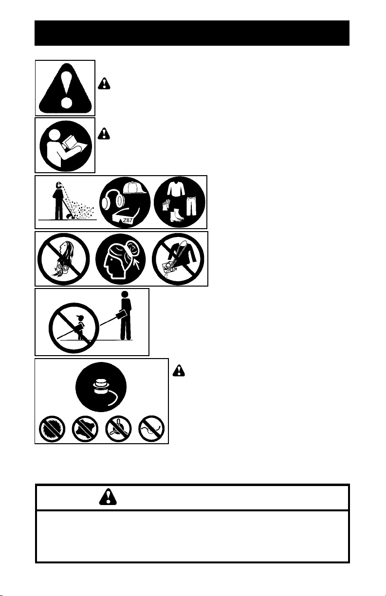
IDENTIFICATION DES SYMBOLES DE SÉCURITÉ
AVERTISSEMENT:
L’emploi négligeant ou impropre de cet appareil pourra entraîner des blessures graves.
AVERTISSEMENT:
ment avant d’utiliser l’appareil. Tout défaut de respecter tous les
instructions peut entraîner des blessures graves aux utilisateur
et/ou spectateurs. Conservez ces instructions.
Ne permettez jamais aux enfants d’utiliser votre
appareil.
Cet appareil à moteur peut devenir dangereux!
Lisez le manuel d’instructions complète-
Le fil de coupe peuvent projette violement
des objets. Vous pourriez perdre la vue
ou être blessé(e)/ aveuglés. Portez
toujours des lunettes de sécurité marquée
Z87. Toujours porter un protecteur de
l’ouïe. Nous recommandons l’utilisation
d’un casque de protection, des pantalons longs, manches longues, des
bottes et des gants.
Attachez--vous les cheveux pour qu’ils
ne dépassent pas les épaules. Attachez
ou enlevez les bijoux, les vêtements amples ou les vêtements qui ont des bretelles, des attaches, des pompons etc. qui
pendent. Ils pourraient se prendre dans
les pièces mobiles.
AVERTISSEMENT:
la tête de coupe et la bobine spécifiée. Utilisez
seulement un fil de coupe recommandé. N’utilisez
jamais de lames, de fléaux, de fil métallique, de
corde, de cordons, etc. L’appareil est conçu uniquement pour une utilisation avec fil de coupe. Tout
défaut de respecter tous les instructions peut
entraîner des blessures graves.
Utilisez seulement
AVERTISSEMENT
Les émissions du moteur de cet outil contiennent des
produits chimiques qui, d’après l’État de Californie,
peuvent causer le cancer, des malformations
congénitales ou autre danger pour la reproduction.
35
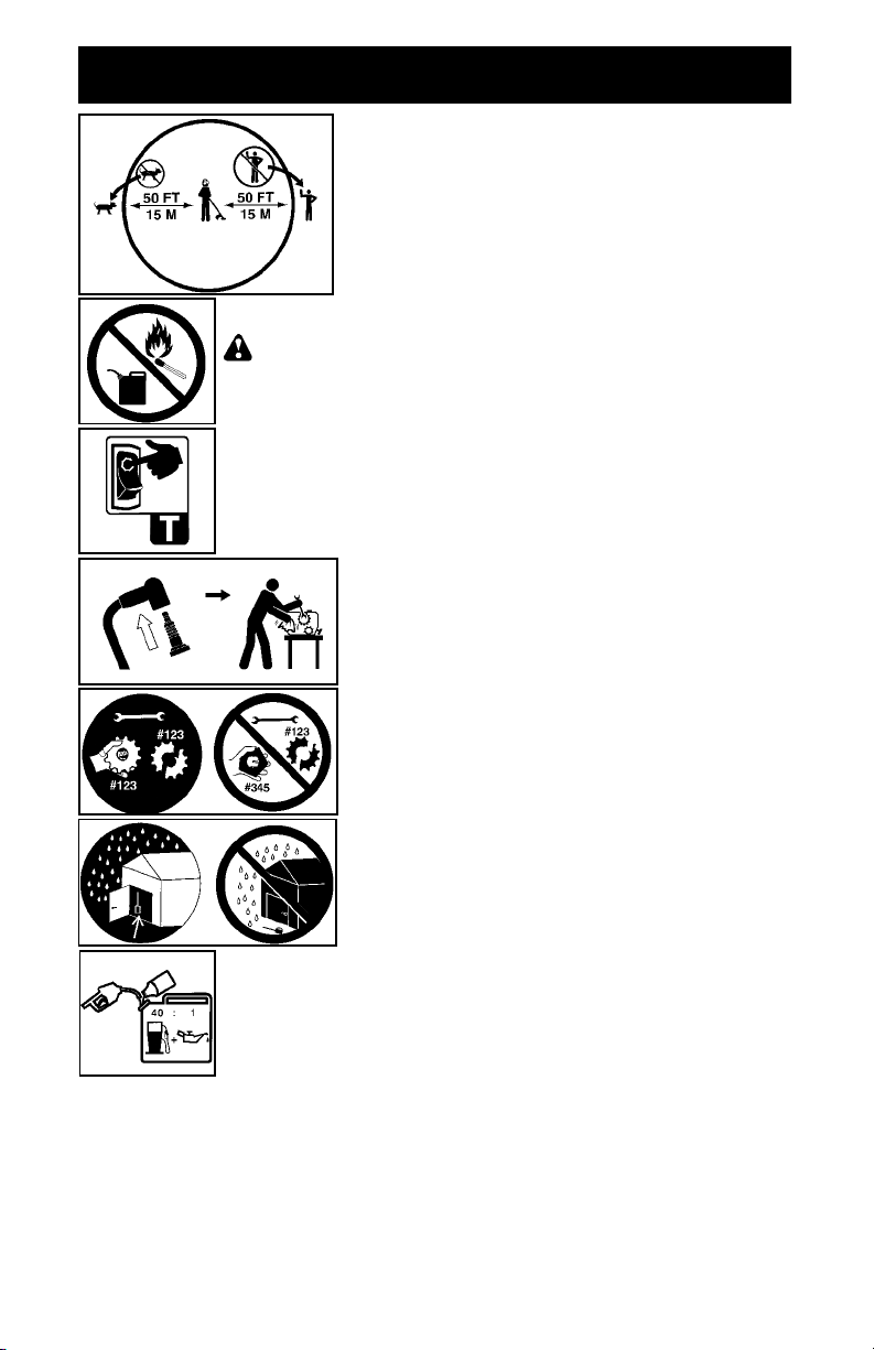
IDENTIFICATION DES SYMBOLES DE SÉCURITÉ
Zone de danger de projection d’objets.
S Le fil de coupe peuvent projeter violement des objets.
S Des tiers peuvent être blessés ou perdre la vue.
S Ne pas laisser les enfants, les spectateurs ou les animaux
s’approcher à moins de 15 mètres (50 pieds).
AVERTISSEMENT:
versé, ou entreposé le carburant ou utilisez l’appareil près de flammes
ou des source d’étincelles (cigares/cigarettes, flammes nues, ou travail
qui peut causer des étincelles).
Pour arrêter le moteur, poussez l’interrupteur STOP et maintenez--le
dans la position STOP jusqu’à ce que le moteur soit completement
arrêté.
Emplacement des vis de réglage du ralenti
Débranchez toujours la bougie avant en nettoyant
ou pendant l’entretien.
Pendant l’entretien de l’appareil, emploient seulement
les pièces de rechange identiques.
Rangez l’outil à l’intérieur. Rangez--le débranché dans
un endroit surélevé et sec, hors de portée des enfants.
Risque d’incendie. Ne jamais mélangé,
Utilisez de l’essence sans plomb et un huile deux temps mélangée
dans un rapport de 40:1 (2,5%).
36
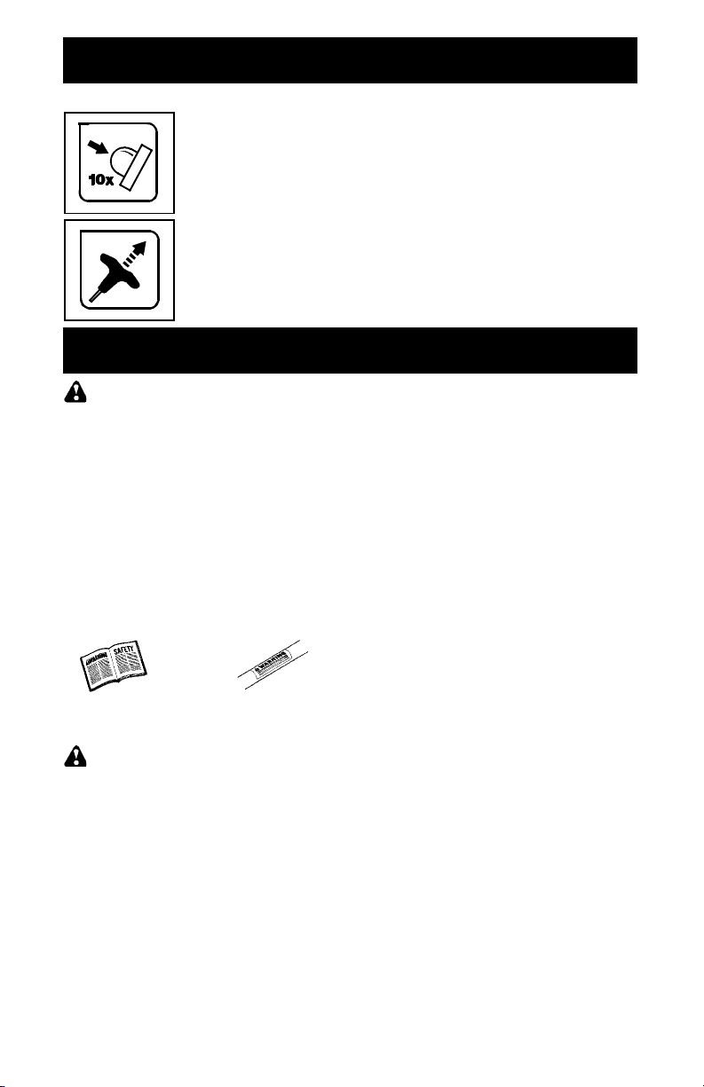
IDENTIFICATION DES SYMBOLES DE SÉCURITÉ
Symboles
de
démarrage
Appuyez 10 fois la poire d’amorçage fermement (appuyant sur la
poire la première fois déplacera la poire d’amorçage qu’un peu et fera un
“clic”).
Tout en maintenant l’appareil en position de démarrage, tirez fort sur la
corde de démarrage jusqu’à ce que le moteur se mette en marche et
fonctionne.
RÉGLES DE SÉCURITÉ
S Portez toujours un protecteur de l’ouïe.
AVERTISSEMENT:
employez n’importequel appareilde jardinage,il
faudra toujours respecter des précautions fondamentales de sécurité afin de réduire le risque
d’incendie et de blessures graves. Lisez et observez toutes les instructions.
L’utilisateur a la responsabilité d’observertoutes
les instructions etavertissements.Lisez lemanuel d’instructions complètement avant d’utiliser
l’appareil!Familiarisez-vous profondément avec
les contrôles etavec l’utilisation correctede l’appareil.Limitez l’utilisationdecetappareil aux personnes quiontlu,qui comprennentet quepeuvent bien respecter les instructions et
avertissements qui se trouvent dans le manuel
etsurl’appareil.Nepermettez jamaisquelesenfants utilisent cet appareil.
MANUEL
D’INSTRUCTIONS
AVERTISSEMENT:
mais de lames ni de dispositifs pour battre au
fléau. Cet appareil a été conçu exclusivement
commecoupeurà ligne.L’utilisationden’importe
quel autre accessoire augmentera le risque de
blessures.
Si vous vous trouvez dans des situations non
déscrites dans ce manuel, soyez prudents et
utilisez votre bon sens. Si vous avez besoin
d’aide, mettez--vous en rapport avec votre
distributeur autorisé de service ou avec le téléphone 1--800--554--6723.
Lorsque vous
INFORMATION DE
SÉCURITÉ SUR
L’APPAREIL
N’employez ja-
SÉCURITÉ DE L’UTILISATEUR
S Équipez--vous bien. Quand vous utilisez ou
entretenez votre appareil, portez toujours
des lunettes de sécurité ou une protection
des yeux similaire (lunettes de sécurité disponibles). La protection des yeux devriez
marquée Z87.
S Pour les travaux poussiéreux, portez tou-
jours un masque.
S Portez toujours des pantalons longs et
épais, des manches longues, des bottes et
des gants. On recommande l’utilisation de
jambières.
S Toujours protection de pieds d’usure. Ne
travaillez pas pieds nus et ne portez pas de
sandales. Tenez--vous à l’écart du fil tournante.
S Attachez--vous les cheveux pourqu’ilsne dé-
passentpaslesépaules. Attachezouenlevez
tous les vêtements ampleset les bijoux ou les
vêtements qui ont des attaches, des bretelles,
des pompons, etc. quipendent.Ils peuventse
prendre dans les pieces mobiles.
S Si vous êtes bien couvert(e), cela vous aid-
era à vous protéger contre les débris et
brins de plantes toxiques qui sont projetés
par le fil qui tourne.
S Soyez vigilant(e). N’utilisez pas l’appareil
quandvous êtesfatigué,maladeou sousinfluence de l’alcool, des drogues ou des
médicaments. Portez attention à ce vous
faites et faites preuve de bon sens.
S Ne mettez pas l’appareil en marche ni lais-
sez pas tourner le moteur dans un endroit
fermé. Respirer la vapeur d’essence peut
vous tuer.
S Conservez les poignée libres d’huile et de
carburant.
SÉCURITÉ DE L’APPAREIL ET
DANS LE ENTRETIEN
S Débranchez toujours la bougie quand vous
faites le maintien, sauf les réglages du
ralenti.
S Inspectez l’appareil et changez les piéces
endommagéesou branlantes avantchaque
utilisation de l’appareil. Réparez toute fuite
de carburant avant d’utiliser l’appareil. Tenez l’appareil toujours en bon état de fonctionnement.
S Remplacez les pièces de la tête de coupe qui
sont ébréchées, craquelées, cassées ou endommagées de n’importe quelle autre façon.
37

S Entretenez l’appareil selon les méthodes
recommandées. Conservez le fil de coupe
à la bonne longueur.
S N’utilisez que le fil de coupe recom-
mandées de marque WEED EATER. Ne
utilisez pas jamais de broche,de corde, de
ficelle, etc.
S Installez--bien la protecteur requise avant
d’utiliser l’appareil. Utilisez la tête de coupe
spécifiée. Assurez--vous qu’elle est bien
installée et que toutes les pièces sont bien
serrées.
S Assurez--vous que l’appareil est correcte-
ment monté selon ce manuel.
S Faites leréglagedu ralentiavec lebout infé-
rieur supporté en haut afin que le fil ne
touche aucun objet.
S Tenez toute autre personne eloignée pen-
dant que vous faites le réglage du ralenti.
S Employez exclusivement les accessoires
et les pièces de rechange WEED EATER
recommandées.
S Faites faire toutes les réparations/tout l’entre-
tienquine sontpas éxpliqués dansce manuel
par le distributeur autorisé de service.
SÉCURITÉ DU CARBURANT
S Mêlez et versez le carburant dehors.
S Éloignez--vous des étincelles et des
flammes.
S Employez un récipient approuvé pourl’ess-
ence.
S Ne fumez pas et ne permettez que per-
sonne fume près du carburant ni pendant
l’utilisation de l’appareil.
S Évitez de renverser le carburant ou le huile.
Essuyez tout les déversements decarburant.
S Éloignez--vous au moins de 3 mètres (10
pieds) de l’endroit de ravitaillage avant de
mettre le moteur en marche.
S Arrêtez le moteur et laissez l’appareil se re-
froidir avant d’enlever le bouchon du réservoir de carburant.
S Rangez toujours le carburant dans un réci-
pient approuvé pour les liquides inflammables.
S Réparez toutefuite de carburant avantd’uti-
liser l’appareil.
S Assurez--vous que le capuchon de rem-
plissage est bien serré après l’ajout de
carburant.
SÉCURITÉ PENDANT DE COUPAGE
AVERTISSEMENT:
l’espace avant chaque utilisation. Enlevez les
objets (pierres, verre cassé, clous, fil de cuivre,
etc.) que le fil pourrait jeter ou qui pourraient se
prendredans la même. Les objets durs peuvent
endommagerlatêtedecoupeetpeuvent êtrejetés et causer des blessures graves.
S Ne laissez ni enfants, ni spectateurs ni ani-
maux s’approcher à moins de 15 mètres. Encouragez--les à porter des protection des
yeux. Arrêtez le moteur immédiatement si la
distance de sécurité n’est pas respectée.
S Utilisez l’appareil exclusivement pour
tondre la pelouse et pour balayer. Ne l’employez pas pour border, élaguer ou tailler.
Inspectez
S Tener les pieds toujours sur une surface
stable et maintenez l’équilibre. Ne vous penchez pas excessivement.
S Tenez tous les membresducorpséloignés du
fil tournante, tête de coupe et du silencieux.
Tenez le moteur toujours au--dessous du niveau dela ceinture. Le silencieux peutcauser
des brûlures graves quand il est chaud.
S Modèles W25CB, W25CF, W25CBK,
W25CFK: Coupez de droite a gauche. Si
vous coupez avec le fil du côté gauche du
protecteur, le fil éloignera les déchets.
S Modèles W25SB, W25SF, W25SBK,
W25SFK: Coupez de gauche a droite. Si
vous coupez avecle fildu côté droiteduprotecteur, le fil éloignera les déchets.
S N’utilisez l’appareil que le jour ou sous une
bonne lumière artificielle.
S N’utilisez l’appareil que pour les travaux in-
diqués dans ce manuel.
TRANSPORT ET ENTREPOSAGE
S Laissez le moteur se refroidir et fixez bien
l’appareil avant de le garder ou de le transporter dans un véhicule.
S Videz le réservoir de carburant avant de
garder ou de transproter l’appareil. Afin de
consommertoutle carburant restant dansle
carburateur, mettez le moteuren marche et
laissez--le tourner jusqu’à ce qu’il s’arrête
tout seul.
S Gardez l’appareilet le combustible dans un
endroit oú les vapeurs d’essence ne peuvent pas entrer en contact avec des étincelles ni des flammes nues des chauffeurs
d’eau, des moteurs ou des interrupteurs
électriques, le chauffage central, etc.
S Gardezl’appareil de façon que personnene
puisse se blesser accidentalement avec le
coupeur du fil. On peut accrocher l’appareil
par l’axe.
S Gardez l’appareil hors de la protée des en-
fants.
REMARQUE SÉCURITÉ:
vibrations à travers l’utilisation prolongée d’appareils à moteur d’essence serrés dans les
mains peut causer des dommages aux vaisseauxsanguinsouauxnerfs danslesdoigts,les
mains et les articulations des personnesquisont
sujets aux maladies de la circulation ou aux enflures anormales. L’utilisation prolongée au
temps froid a été relationée aux dommages des
vaisseaux sanguins dans des personnes qui
autrement ont une bonne santé. Si vous avez
des symptomes tels que l’engourdissement, la
douleur, manque de foces,changementde couleurou texturede lapeau,ou pertede sensation
dans les doigts, les mains ou les articulations,
arrêtez l’utilisation de cet appareil et consultez
un médecin. Les systèmes anti--vibration ne
peuvent pas garantir que ce type de problèmes
seraévité.Lesutilisateurs quitravaillent avecles
appareils à moteurcontinuellement devront surveiller leur condition physique, et la condition de
l’appareil, soigneusement.
REMARQUESPÉCIALE:
ent equipée d’un silencieux limiteur de température et unécranpare--étincelles afindesatisfaire
les conditions des codes de Californie 4442 et
L’exposition aux
Votre appareilvi-
38
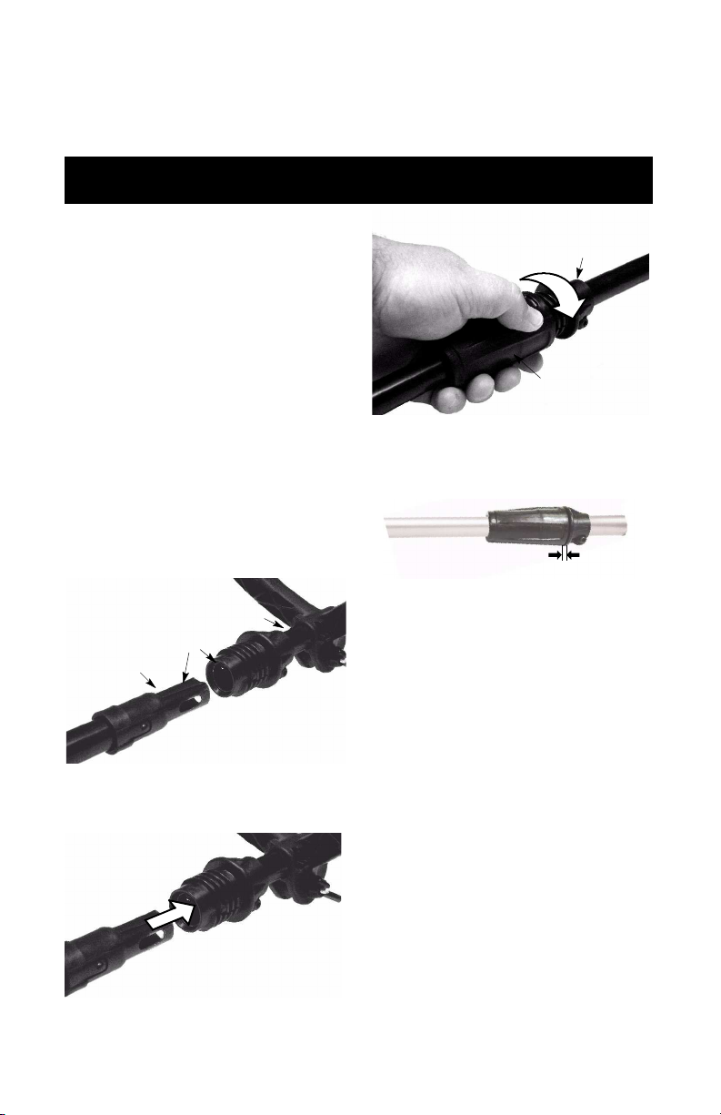
4443. Toutes les terres fiscales boisées et les
états de Californie, Idaho, Maine, Minnesota,
Nouvelle Jersey, Orégon etWashingtonexigent
par loi un écran pare--étincelles dans beaucoup
de moteurs de combustion interne. Si vous utilisez l’appareil où il y a de telles règles, vous êtes
juridiquement responsable de l’installation et du
maintien de ces pièces.Le manquede ces con-
MONTAGE
ditions est une violation de la loi. Pour l’usage
normal de propriétaire d’une maison, le silencieux et d’un écran pare--étincelles n’exigeront
aucun service. Après 50 heures d’utilisation,
nous recommandons que votresilencieux à entretenir ou est remplacéparvotre distributeur autorisé de service.
ATTENTION :
lé, vérifiez chaque étape de l’assemblage
pourvous assurer qu’il est bien fait et que tous
les raccords sont bien serrés.
Vérifiez que les pièces soient en bon état.
N’utilisez pas de pièces endommagées.
REMARQUE:
ou trouvez des pièces endommagées, appelez au 1-800-554-6723.
Il est normal que le filtre à carburant cliquette
dans le réservoir de carburant vide.
Il est normal que vous trouviez un résidu de
carburant ou d’huile sur votre silencieux, à la
suite des réglages et des essais de carburateur faits par le fabricant.
Si l’appareilest déjàassemb-
Si vous avez besoin d’aide
MONTAGE DE L’AXE
(Modèles W25CBK, W25CFK,
W25SBK, W25SFK)
ATTENTION :
posez l’appareil sur une surface plane pour
qu’il soit parfaitement stable.
1. Alignez les rainures sur l’axe supérieur et
l’axe inférieur.
Axe inférieur
2. Réunissez l’axe inférieur dans l’axe supérieur en les poussant l’un dans l’autre pour
les emboîter.
3. Faitesglisserles partiesinférieureetsupérieure du manchon de verrouillage l’une
sur l’autre et serrez en tournant dans le
sens horaire.
Lors du montage de l’axe,
Axe supérieur
Rainures
Partie supérieure du
manchon de verrouillage
Partie inférieure
du manchon de
verrouillage
REMARQUE:
serrer le manchonde verrouillage inférieuresi
les axes inférieure et supérieure ne sont pas
complètement emboîtés (l’espace est plus
large que 1/4 pouce).
Espace est plus large que 1/4 pouce
Il ne sera pas possible de
RÉGLAGE DU POIGNÉE
(Models W25CB, W25SB, W25CF,
W25SF)
ATTENTION :
néeauxiliaire,assurez--vous qu’ellereste au-dessus de l’étiquette de sécurité et au--dessous de la marque ou de la flèche sur l’axe.
1. Desserrez l’écrou papillon ou le bouton de
la poignée.
2. Faites tourner la poignée sur l’axe jusqu’à
ce qu’elle soit droite; resserrez l’écrou papillon.
Quand vous ajustez la poig-
RÉGLAGE DU POIGNÉE
(Models W25CBK, W25CFK,
W25SBK, W25SFK)
ATTENTION :
poignée auxiliaire, assurez-vous qu’ellereste
au--dessus du manchon de verrouillage
supérieureet au--dessous de la marqueou de
la flèche sur l’axe.
1. Desserrez l’écrou papillon ou le bouton de
la poignée.
2. Faites tourner la poignée sur l’axe jusqu’à
ce qu’elle soit droite; resserrez l’écrou papillon.
Quand vous ajustez la
INSTALLATION DU PROTECTEUR
ATTENTION :
protecteur soit installé correctement. Le protecteur offre une protection partiale du risque des
objets jetés contre l’utilisateur et autres personnes etilvient equipéd’un lamede limiteurdu
Il fest indispensable que le
39
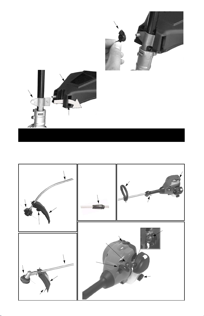
filquicoupe l’excès de fil. Lelame delimiteurdu
Protecteur
fil (qui se trouve en bas du protecteur) est bien
tranchant et peut vous blesser.
Pour bien identifier toutes les pièces, référez-vous à l’illustration FAMILIARISEZ--VOUS
AVEC VOTRE APPAREIL dans la sectionUTILISATION.
1. Enlevez l’écrou papillon le protecteur.
2. Insérez le support dans la fente comme le
montre la figure.
3. Faites pivoter le protecteur jusqu’à ce que
le boulon passe dans le trou du support.
4. Resserez fortement l’écrou papillon sur le
boulon.
Support
Fente
Écrou papillon
UTILISATION
FAMILIARISEZ--VOUS AVEC VOTRE APPAREIL
LISEZ BIEN CE MANUEL ET LES RÈGLES DE SÉCURITÉ AVANT D’UTILISER VOTRE
APPAREIL.Comparez l’appareil aux illustrations pour bienvoir où se trouvent les commandes.
Conservez ce manuel pour vous y reporter plus tard.
Modèles:
W25CB, W25CF,
W25CBK, W25CFK
Axe
Modèles:
W25CBK, W25CFK,
W25SBK, W25SFK
Silencieux
Poignée auxiliaire
Tête de
coupe
Protecteur
Lame de limiteur du fil
Modèles:
W25SB, W25SF,
W25SBK, W25SFK
Tête de
coupe
Lame de limiteur du fil
Axe
Protecteur
Douille de
fermeture
Interrupteur
STOP
Poignée de
la corde de
mise en
marche
40
Bougie
Gâchette d’accélérateur
Poire
d’amorçage
Capuchon de
remplissage
(carburant)

INTERRUPTEUR STOP
Pour
arrêter
le
moteur
,
Vous utilisez l’interrupteur STOP pour arrêter
votre moteur. Pour arrêter le moteur, poussez
l’interrupteur et maintenez--le dans la position
STOP jusqu’à ce que le moteur soit completement arrêté.
POIRE D’AMORÇAGE
La POIRE D’AMORÇAGE enlève l’air des
carburateur et conduites de carburant et les
remplit de carburant. Cela vous permet de
mettrele moteuren marche en tirant moins de
fois le corde de mise en marche. Utilisez la
poire d’amorçage en pressant et un lui permettant de reprendre sa forme initiale.
AVANT DE FAIRE DÉMARRER LE
MOTEUR
AVERTISSEMENT:
commencer, ne manquez pas de lire les
instructions de traitement du carburant des
règles de sécurité de ce manuel. Si vous ne
les comprenez pas, n’essayez pas de remplir
votre appareil. Demandez l’aide de quelqu’un
quiles comprendou appelez notre ligned’aide
aux consommateurs au 1-800-554-6723.
Avant de
REMPLISSAGE DU RÉSERVOIR DE
CARBURANT
AVERTISSEMENT:
puchonde remplissage (carburant) lentement
quand ajoutant plus de carburant à l’appareil.
Enlevez le ca-
RENSEIGNEMENTS UTILES
Pour obtenir le bonmélange
d’huile et d’essence, versez
3,2 onces d’huile synthétique à deux temps dans un
gallon d’essence fraîche.
IMPORTANT:
pour fonctionner avec du carburant sans
plombayant un indiceminimal d’octane de 87
(méthodeR+M/2),avec un mélange d’éthanol
jusqu’à 10% maximum par volume (E-10).
Avant l’utilisation, le carburant doit être
mélangé avec une huile synthétiquede bonne
qualité pour moteur refroidi à l’air 2 temps
conçue pour un mélange dans un rapport
40:1. L’huile synthétique Poulan/WEED
EATER est recommandée. Mélanger le
carburant et l’huile dans une proportion 40:1.
Le rapport 40:1 est obtenu en mélangeant 95
ml (3,2 onces liquide) d’huile avec 4 litres (1
gallon) de carburant sans plomb. NE PAS
UTILISER d’huile de qualité automobile ou
marine. Ces huiles endommageront le
moteur. Lors du mélange du carburant, suivre
les instructions sur le contenant. Dès que
l’huile est ajoutée au carburant, secouer
quelques secondesle contenant pour assurer
un bon mélange. Toujours lire et suivre les
règles de sécurité en lien avec le carburant
avant de procéder à l’avitaillement de la
machine. Acheter des quantités d’essence
pouvant être consommées dans les 30 jours
afin de garantir la fraîcheur de l’essence.
MISE EN GARDE :
uniquement du carburant dansla machine. Cela
pourrait occasionner des dommages
permanents au moteur et annuler la garantie
limitée. Ne pas utiliser de carburants de
remplacementtels quedesmélanges d’éthanol
Cet équipement est conçu
Ne jamais utiliser
à plus de 10% par volume (E-15, E-85) ou tout
carburant additionné de méthanol. Le recours à
ces carburants peut entraîner des problèmes
majeurs au niveau de la performance et de la
durabilité du moteur.
RENSEIGNEMENTS UTILES
Si votre interrupteur indique qu’il faut pousser pour
arrêter, il est toujours en
position «ON».
ARRÊT DU MOTEUR
S
poussez l’interrupteur
STOP et maintenez--le
dans la position STOP
jusqu’à ce que le moteur
soit completement arrêté.
DÉMARRAGE DU MOTEUR
AVERTISSEMENT:
coupetourne quand vous mettezle moteuren
marche. Évitez tout contact avec le silencieux. Un silencieux chaud peut causer des
brûlures sérieuses.
La tête de
RENSEIGNEMENTS UTILES
Si vous ne réussissez pas
à faire démarrer votre moteur après avoir suivi ces
instructions, appelez le
1--800--554--6723.
POSITION DE
DÉMARRAGE
DÉMARRAGE D’UN MOTEUR FROID
(ou après remplissage du réservoir
à carburant)
REMARQUE:
face plane. NE serrez pas la gâchette d’accélérateur jusqu’à ce que le moteur se mette
en marche et fonctions. Si la gâchette d’accélérateur est tirée avant que le moteur démarre, le moteur ne vas pas démarré!
Placez l’appareilsur unesur-
41

1. Appuyez 10 fois la
2.T
outenmaintenant
poire d’amorçage
fermement (appuyant
sur la poire la première
fois déplacera la poire
d’amorçage qu’un peu et
fera un “clic”).
Poignée de la
corde de mise
en marche
Gâchette
d’accélérateur
Poire
d’amorçage
pendant plusde15minutessans êtreemployé,il
seranécessairede démarrerl’appareil paraprès
les étapessousDÉMARRAGEDU MOTEUR A
FROID ou après les étapes de démarrage
montrées sur l’appareil.
DÉMARRAGE D’UN MOTEUR NOYÉ
Appuyez et maintenez appuyée la gâchette
d’accélération. Tirez fort la corde de mise en
marche en serrant la gâchette d’accélération
jusqu’à ce que le moteur fonctionne. Cela peut
vous obliger à tirerla poignée dudémarreur plusieurs fois selon le degré de noyade dumoteur.
Si l’appareil ne part pas, consultez TABLEAU
DE DÉPANNAGE ou appelez le
1-800-554-6723.
INSTRUCTIONS D’UTILISATION
On luirecommandequele moteur pour nepas
être fonctionnépour plus d’une minute à la vitesse maximum.
POSITIONS D’UTILISATION
Modèles W25CB, W25CF, W25CBK,
W25CFK:
PORTEZ TOUJO
Protecteur de l’ouïe
Les
cheveux
au--dessus
des épaules
Protection des
yeux
l’appareil en position de
démarrage, tirez fort sur
la corde de démarrage
jusqu’à ce que le moteur
se mette en marche et
fonctionne, mais pas plus
de 10 fois.
3. Unefois quele moteur démarre, permettez
à l’appareil de marcher environ 30
secondes, puis serrez entièrement la
gâchette d’accélérateur pour désengager
le système de démarrage.
4. Si l’appareil ne part pas, réferez--vous a la
section DÉMARRAGE D’UN MOTEUR
CHAUD.
DÉMARRAGE D’UN MOTEUR CHAUD
1. Tirez et relâcher la gâchette pour faire en
sorte que le système de démarrage à froid
a été désengagé.
2. Lorsque le moteur est chaud (utilisé dans
les 15 dernièresminutes), tout en maintenant l’appareil en position de démarrage,
tirez fort sur la corde
de démarrage jusqu’à ce que le moteur se
mette en marche et fonctionne, mais pas
plus
de 10 fois.
3. Si l’appareil ne part pas, réferez--vous a la
section DÉMARRAGE D’UN MOTEUR
NOYÉ.
REMARQUE:
indiquées pour un moteur chaud peut être
employé à moins de 15 minutes après que
l’appareil est arrêtée. Si l’appareil se repose
Normalement, les consignes
Pantalons
Longs
Gros
Chaussures
Gants
Coupez
de droite a
gauche.
Modèles W25SB, W25SF, W25SBK,
W25SFK:
PORTEZ TOUJOURS:
Protecteur de l’ouïe
Les
cheveux
au--dessus
des épaules
Pantalons
Longs
Gros
Chaussures
Coupez de gauche a droite.
Protection des
yeux
Gants
42

AVERTISSEMENT:
Le
boutdufil
Le
fil
est
forcé
dans
des lunettes de sécurité. Ne vous penchez jamais sur la tête de coupe. Des pierres ou des
débris peuventricocher ouêtreprojetés survos
yeux et sur votrevisage etvous rendre aveugle
ou vous causer des blessures sérieuses.
Maintenez l’équilibre. Tenez l’appareil à deux
mains, la main droite sur la poignée arrière /
gâchetteetla main gauche surla poignéeauxiliaire. Toujours garder le moteur et la tête de
coupe au--dessous de niveau de la taille.
Ne faites pas marcher le moteur à moteur à
une vitesse plus élevée que c’est nécessaire.
Le fil de coupe efficacement quand le moteur
marche à moins que son accélération maximum. À plus basse vitesse, le moteur fait
moins de bruit et moins de vitesse. Le fil de
coupe dure plus longtemps et a moins de
chances de rentrer dans la bobine.
Relâchez toujours la gâchette d’accélération
et permettez au moteur de tourner au ralenti,
quand vous ne coupez pas d’herbe.
Pour arrêter le moteur:
S Lâchez la gâchette d’accélérateur.
S Poussezl’interrupteur STOPet maintenez--
le dans la position STOP jusqu’à ce que le
moteur soit completement arrêté.
Portez toujours
AVANCE DU FIL DE COUPE
(Modèles W25CB, W25SB, W25CBK,
W25SBK)
Le fil de coupe avance d’environ 5 cm (2
pouces) chaque fois que le bas de la tête de
coupe tape contre le sol avec le moteur qui
marche à pleine accélération. La longueur de
fil la plus efficace est la longueur maximum
permise par le lame de limiteur du fil.
Laissez toujours le protecteuren place quand
vous utilisez l’appareil.
Pour avance du fil:
S Faites marcher le moteur à pleine accéléra-
tion.
S Tenez la tête de coupe parallèlle aux zones
d’herbe et au dessus d’elles.
S Tapez légèrement le bas de la tête de coupe
contrele solunefois. Environ5cm (2pouces)
de fil sortent chaque fois que vous tapez.
Tapez toujours la tête de coupe contre le sol
dans une zone d’herbe. Si vous le tapez contre des surfaces comme du béton ou de l’asphalte, cela risque d’occasionner une usure
excessive de la tête de coupe.
Si le fil est tellement usé qu’il n’est pas plus
longque5 cm (2 pouces), oumoins, il fautplus
d’une tape pour obtenir la longueur du fil la
plus efficiente.
AVERTISSEMENT:
èles W25CB, W25SB, W25CBK, W25SBK,
n’utilisez que le fil de 2 mm (0,080 pouce) de
diamètre. Les fils de coupe d’autres tailles
n’avancent pas bien et peuvent causer des
blessures sérieuses. Pour les modèles
W25CF, W25SF, W25CFK, W25SFK, n’utilisez que le fil de 2,4 mm (0,095 pouce) de
diamètre. N’utilisez pas d’autres matériaux
commelefil de fer, laficelle,la corde, etc. Lefil
de fer peut se briser pendant la coupeet deve-
Pour les mod-
nir un missile dangereux qui peut causar des
blessures graves.
MÉTHODES DE COUPE
AVERTISSEMENT:
tesse minimum et ne surchargez pas le fil
quand vous coupez autour d’objets durs
(rochers, gravier, piquets de barrière, etc.) qui
peuvent endommager la tête de coupe, se
mêlerdans lefil ou êtreprojetésen causantun
danger sérieux.
S C’est le bout de la fil qui coupe. Vous obtien-
drez le meilleurrendementet l’usureminimum
du fil en ne forçant pas le fil dans la zone à
couper. Nous vous montrons ci--dessous la
bonne et la mauvaise monière de couper.
coupe.
Bonne méthode
S Lefil coupefacilement l’herbeet lesmauvai-
ses herbes autour des murs, des barrières,
des arbres et des parterres de fleurs, mais il
peutégalementcouperl’écorcedes arbres ou
des arbustes et marquer les barrières.
S Pourtaillerouraser l’herbe, utilisez l’appareil
à une puissance inférieureà la pleineaccélération pour augmenter la durée du fil et
baisser l’usure de la tête, en particulier:
S Quand vous faites des travaux de coupe
légers.
S Quand vous coupez près d’objets autour
desquels le fil peur s’emmêler, comme
des poteaux, des arbres ou des haies en
fil de fer.
S Pourtondreou balayer, utilisez toutel’accé-
lération pour faire un bon travail propre.
TAILLE-- Maintenez lebas dela têtede coupe
à environ 8 cm (3 pouces)du sol et à unangle.
Ne permettez qu’auboutdu fil deprendrecontact avec l’herbe. Ne forcez pas la pénétration
du fil de coupe dans la zone de travail.
Taille
RASAGE -- La technique de rasage retire
toute végétation non désirée. Maintenez le
bas de la tête de coupe à environ 8 cm (3
pouces) du sol et à un angle. Permettez à la
pointe du fil de frapper le sol autour des
Utilisez la vi-
la zone de travail.
Mauvaise méthode
8 cm (3
pouces) au
dessus du sol
43

arbres, des piquets, des monuments, etc.
Avec cette technique, le fil s’use plus vite.
Rasage
FAUCHAGE -- Votre coupe--herbe est idéal
pour faucher l’herbe dans les endroits que les
tondeuses conventionnelles ne peuvent atteindre.En positionde fauchage, maintenezle
fil parallèle au sol. Évitez de presser la tête
dans le sol car celapeut raserle sol et endommager l’appareil.
Fauchage
ENTRETIEN
AVERTISSEMENT:
toujours le fil de la bougie quand vous ferez des
réparations, sauf les réglages du ralenti.
RENSEIGNEMENTS UTILES
IMPORTANT :
fectuer toutes les réparations
autres que les opérations
d’entretien recommandées
dans le manuel d’instructions
par un distributeur autorisé
Si un réparateur qui n’est pas un distributeur
autorisé fait des réparations sur l’appareil,
WEED EATER ne paierapas les réparations
sous garantie. Vous êtes responsable d’entretenir et de faire l’entretiengénéral de votre
appareil.
VOIR S’IL Y A DES RACCORDS/
PIÈCES DESSERRÉ(E)S
S Le couvercle de la bougie
S Le filtre à air
S Les vis du boîtier
S Les vis de la poignée auxiliaire
S Le protecteur
S Capuchon de remplissage
VOIR S’IL Y A DES PIÈCES
ENDOMMAGÉES/USÉES
Contactez un distributeur autorisé de service
pour le remplacement des pièces endommagées ou usées.
de service.
Débranchez
Faites ef-
BALAYAGE -- Vous pouvez utiliser l’action de
balayage du fil de coupe pour nettoyer vite et
facilement. Maintenez le fil parallèle aux surfaces balayées etau dessus d’elles etbougez
l’appareil d’un côte à l’autre.
Balayage
S L’interrupteur STOP -- Assurez--vous que
l’interrupteur STOP fonctionne bien en
poussant sur l’interrupteur et en le maintenant en position STOP. Assurez--vous que
le moteur s’arrête. Remettez ensuite en
marche l’appareil et continuez.
S Leréservoir de carburant-- Arrêtezd’utiliser
l’appareil si le réservoir de carburant,
capuchon de remplissage, et/ou tuyau de
carburantmontre des signes dedommages
ou de fuite.
S Le protecteur -- Arrêtez--vous d’utiliser l’ap-
pareil si le protecteur est endommagé.
INSPECTEZ ET NETTOYEZ L’APPAREIL ET LES ÉTIQUETTES
S Après chaque usage, inspectez l’appareil
complètepour déceler les pièces lâches ou
endommagées.
Nettoyez l’appareil avec un chiffon humide
et un détergent doux.
S Sécher avec un chiffon propre et sec.
NETTOYAGE DU FILTRE À AIR
Un filtre à air sale diminue le rendement du
moteur et augmente la consommation de carburant et les émissions nocives. Nettoyez
toutes les 5 heures de fonctionnement.
1. Nettoyez le couvercle du filtre à air et la
zone quil’entoure pour empêcher la saleté
de tomber dansla chambrede carburateur
quand le couvercle est enlevé.
2. Ouvrez la couvercle de filtre à air en appuyantsur le bouton(voirl’illustration). Enlevez le filtre.
44

REMARQUE:
dans de l’essence ou dans un autre solvant inflammable pour éviter de courir un danger d’indendie ou de produire des émissions nocives.
3. Lavez le filtre dans de l’eau savonneuse.
4. Laissez sécher le filtre.
5. Réinstallez le filtre à air et fermez la couvercle.
Ne nettoyez pas le filtre à air
Bouton
Filtre
à air
Couvercle du filtre à air
SILENCIEUX ET ÉCRAN DU
PARE-ÉTINCELLES
Durantl’utilisationde l’outil,des dépôts decarbone se forment sur le silencieux et le pareétincelles.
RÉPARATIONS ET RÉGLAGES
Pourl’usagenormalde propriétaired’unemaison, cependant, le silencieux et d’un écran
pare--étincelles n’exigeront aucun service.
Après 50 heures d’utilisation, nous recommandons que votre silencieux à entretenir ou
est remplacé par votre distributeur autorisé de
service.
REMPLACEMENT DE LA BOUGIE
Remplacez la bougie chaque année pour assurer un démarrage facile et un meilleur fonctionnement du moteur. Réglez l’écart de la
bougieà 0,6 mm (0,025 pouce). Le cycle d’allumage est fixe et ne peut pas être ajusté.
REMARQUE:
nadiens seulement: Ce système d’allumage
par étincelles est conforme à la norme
NMB--002 du Canada.
1. Tournez, puis tirez le couvercle de bougie.
2. Enlevez la bougie du cylindre et jetez--la.
3. Pour les modèlesseulementaux Ètats-
Unis: Remplacez-la par une bougie
Champion RCJ-6Y.
Pour les modèles Canadiens seulement:
Remplacez-la par une bougie Champion
QCJ-6Y.
4. Et serrez-la à l’aide d’une clé à douille de
19 mm (3/4 pouce).
5. Réinstallez le couvercle de bougie.
Pour les modèles Ca-
REMPLACEMENT DU FIL DE COUPE
(Modèles W25CB, W25SB, W25CBK,
W25SBK)
AVERTISSEMENT:
èles W25CB, W25SB, W25CBK, W25SBK,
n’utilisez que le fil de 2 mm (0,080 pouce) de
diamètre. Les fils de coupe d’autres tailles
n’avancent pas bien et peuvent causer des
blessures sérieuses. Pour les modèles
W25CF, W25SF, W25CFK, W25SFK, n’utilisez que le fil de 2,4 mm (0,095 pouce) de
diamètre. N’utilisez pas d’autres matériaux
commelefil de fer, laficelle,la corde, etc. Lefil
de fer peut se briser pendant la coupeet devenir un missile dangereux qui peut causar des
blessures graves.
1. Enlevez la bobineen tirant fermementsur
le bouton de tapage.
2. Nettoyez toute la surface du moyeu et de
la bobine.
3. Remplacez avec une bobine pré-enroulée ou coupez deux longueurs de 3,8
mètres (12-1/2 pieds) du fil de marque
WEED EATER avec diamètre 2 mm
(0,080 pouces).
4. Insérez les extrémités du fil dans le petit
trousà l’intérieurdela bobine,sur unelongueur d’environ 1 cm (1/2 pouce).
Pour les mod-
Petit
Bobine
Poussez le fil
dans la fente
Moyeu
Poussez le fil
dans la fente
Trou de sortie
5. Embobinez le fildans la bobine en maintenant sa tension et avec régularité. Embobinez dans la direction des flèches que
vous trouverez sur la bobine.
6. Poussez lefil dans la fentes, en laissant 7
à 12 cm (3 à 5 pouces) non embobinés.
7. Insérez le fil dans les trous de sortie du
moyeu, comme le montre l’illustration.
trous
Trou de sortie
45

8. Alignez les fentes avec le trous de sortie
Orifice
de
du fil.
9. Poussez la bobine dansle moyeujusqu’à
ce qu’elle soit fixée en place.
10. Tirez le fil qui sort du moyeu pour lelibérer
de la fentes.
REMPLACEMENT DU FIL DE COUPE
(Modèles W25CF, W25SF, W25CFK,
W25SFK)
AVERTISSEMENT:
èles W25CB, W25SB, W25CBK, W25SBK,
n’utilisez que le fil de 2 mm (0,080 pouce) de
diamètre. Les fils de coupe d’autres tailles
n’avancent pas bien et peuvent causer des
blessures sérieuses. Pour les modèles
W25CF, W25SF, W25CFK, W25SFK, n’utilisez que le fil de 2,4 mm (0,095 pouce) de
diamètre. N’utilisez pas d’autres matériaux
commelefil de fer, laficelle,la corde, etc. Lefil
de fer peut se briser pendant la coupeet devenir un missile dangereux qui peut causar des
blessures graves.
Pour bien faire fonctionner votre appareil, vous
devez remplacer lefil decoupe quand il est usé
à moins de 7 cm (3 pouces) de longueurà partir
de l’extrémité des tunnels de positionnement situés de chaque côte de la tête de coupe.
1. Retirez et mettez au rebut le fil usé avant
d’installer le fil neuf.
2. Nettoyez toute la surface de la tête de
coupe.
3. Insérez les extrémités du fil dans les deux
orifices de guidagesitués sur le devantde
la tête de coupe.
Pour les mod-
5. Tirez les extrémités du fil pour le serrer.
Lorsque le fil est correctement installé, la
longueurdoit êtreidentiquede chaquecôté.
REMPLACEMENT DE LA TÊTE DE
COUPE (Modèles W25CB, W25SB,
W25CBK, W25SBK)
1. Tenirle chapeauprotège--poussière avec
uneclé afin d’empêcher l’arbre detourner
pendant la retirez et installez la tête de
coupe.
Chapeau
protège-poussière
2. Enlevez la tête de coupe en tournant dans
le sens contraire des aiguilles d’unemontre
(vu depuis le bas de l’appareil).
3. Visser la tête de coupe de rechange sur
l’arbre en tournant dans le sens aiguilles
d’une montre. Serrez solidement.
REMPLACEMENT DE LA TÊTE DE
COUPE (Modèles W25CF, W25SF,
W25CFK, W25SFK)
1. Alignezletrou du chapeauprotège--poussière avec celui sur le côté de la boîte de
vitesses en tournant le chapeau protège-poussière.
2. Entrez un petit tournevis dans les orifices
alignés. Celaempêcheral’arbrede tourner pendant que vous retirez et installez la
tête de coupe.
Orifices de
guidage
Orifices de
guidage
4. Continuez de faire passer le fil à travers
les orifices jusqu’à ce que le fil soit
complètement tenduà travers les orifices
de sortie latéraux.
sortie latéral
Orifice de
sortie latéral
Tournevis
3. En maintenant le tournevis en position,
enlevezlatêtedecoupeentournantdansle
sens des aiguilles d’une montre (vu depuis
le bas de l’appareil).
4. Vissez le tête de coupe de rechange dans
l’arbre en tournant dans le sens contraire
des aiguilles d’une montre. Serrez bien.
5. Enlevez le tournevis.
RÉGLAGE DU RALENTI
AVERTISSEMENT:
sonneapprocherlors du réglage du ralenti. La
tête de coupe tourne pendant la plus grande
partie de cette procédure. Portez votre matérial de protection et observez toutes les précautions de sécurité.
Votre carburateur a été soigneusement réglé
à l’usine. Des ajustements du ralenti peuvent
être nécessaires si vous vous trouvez dans
l’une des situations suivantes:
Ne laisser per-
46

S Le moteur ne tourne pas au ralenti lorsque
l’accélérateur est relâché.
Pour effectuer le réglage, posez l’appareil de
façon à ce que l’accessoire de coupe soit
éloigné du sol etqu’il nepuisse toucheraucun
objet. Tenez l’appareil à la main lorsqu’il
tourne et que vous le réglez. Maintenez l’accessoire de coupe et le silencieux éloignés de
toute partie de votre corps.
Pour réglage du ralenti :
Démarrez le moteur et laissez--le se
réchauffer pendant 4--5 minutes pendant la
coupe lourde, ou pendant 10--15 minutes
pendant la coupe modérée.Laissez le moteur
tourner au ralenti. Ajustez la vitesse jusqu’à
ce que le moteurtourne sanscaler (ralentitrop
lent).
S Tournez la vis de réglage au ralenti dans le
sens des aiguilles d’une montre pour aug-
menter la vitesse du moteur.
S Tournez la vis de réglage au ralenti dans le
sens inverse à celui des aiguilles d’une
montre pour dimineur la vitesse.
RANGEMENT
Vis de ralenti
Pour toute aide supplémentaire ou si vous
n’êtespas sûr de la façon deréaliser cetteopération, contactez un distributeur autorisé de
service ou appelez au 1--800--554--6723.
ATTENTION :
vantes après chaque utilisation:
S Laissez se refoidir l’appareil, et attachez
l’appareil avant de l’entreposer ou de le
transporter.
S Entreposez l’appareil et le carburant dans
un en droit bien ventilé, où les vapeurs de
carburant de peuvent pas être en contact
avec des étincelles ou des flammes en
provenance d’appareils de chauffage de
l’eau, des moteurs électriques ou des inter-
rupteurs, des chaudières de chauffage,etc.
S Entreposez l’appareil avec tous les méca-
nismes de protection en place. Placez l’ap-
pareil de manière à ce qu’aucun objet cou-
pant ne puisse causer accidentellement
des blessures.
S Entreposez l’appareil et le carburant hors
de la portée des enfants.
Exécutez les étapes sui-
SAISONNIÈRE RANGEMENT
Préparez l’appareil pour l’entreposage à la fin
de la saison ou si vous necomptez pas l’utiliser pendant au moins 30 jours.
Avant d’entreposer votre appareil pendant
une longue période:
S Nettoyez l’appareil entière avant d’entre-
poser pendant une longue période.
S Rangez--le dans un endroit propre et sec.
S Huilez légèrement lessurfaces externes en
metal.
SYSTÈME DE CARBURANT
Voir le message IMPORTANTse rapportantà
l’usage de carburant approprié dans votre
moteur dans la section du FONCTIONNEMENT de ce manual.
Un agent stabilisateur de carburant constitue
une alternative acceptable pour minimiser la
formation de dépôts de gomme pendant l’entreposage.
Ajoutez l’agent stabilisateur à l’essence dans
le réservoir ou dans le bidon d’essence. Suivez les instruction de mélangeinscrites sur le
bidon de l’agent stabilisateur. Faites marcher
le moteur au moins 5 minutes après avoir
ajouté l’agent stabilisateur.
RENSEIGNEMENTS UTILES
Quand vous conservez un
mélange d’huile et d’essence, l’huile se sépare de
l’essence avec le temps.
Nous vous recommandons
de secouer le bidon chaque semaine pour assurer
un bon mélange de l’huile
et de l’essence.
MOTEUR
S Enlevez la bougie et versez le cuiller à thé
d’huile de moteur 2 temps (refroidi à air)
dans l’ouverture de la bougie. Tirez lentementle cordede mise en marche 8à 10 fois
pour répartir l’huile.
S Remplacez la bougie par une neuve de la
catégorieet de lagamme thermique recommandées.
S Nettoyez le filtre à air.
S Vérifiez l’ensemble de l’appareil pour bien
revisser toutes les vis, les boulons et les
écrous. Remplacez toute pièce endommagée, cassée ou usée.
S Au début de la saison suivante, utilisez uni-
quement du carburant frais, composé par le
bon rapport d’essence à l’huile.
AUTRES RECOMMANDATIONS
S N’entreposez pas d’essence pour la saison
suivante.
S Remplacez votre essence si le réservoir ou
le bidon commence à rouiller.
47

T
ABLEAU
DE
DÉP
ANNAGE
AVERTISSEMENT:
d’exécuter n’importe lequel des remèdes recommandés ci--dessous autre que les
remèdes qui exigent l’exécution de l’appareil.
Toujours arrêtez l’unité et débranchez la bougie avant
PROBLÈME CAUSE REMEDY
Le moteur
refuse de
démarrer.
Le moteur
ne tourne
pas bien au
ralenti.
Le moteur
n’accélère
pas, manque
de puissance
ou meurt
sous la
charge.
Le moteur
fume trop.
Le moteur
surchauffe.
1. Moteur noyé
2. Réservoir de carburant
vide.
3. La bougie ne fait pas feu.
4. Le carburant n’atteint pas
le carburateur.
5. Le carburateur exige un
réglage.
1. Le carburateur exige un
réglage.
2. Joints du vibrequin usés
3. Compression basse
1. Filtre à air sale
2. Bougie encrassée
3. Le carburateur exige un
réglage.
4. Accumulation de carbone.
5. Compression basse.
1. Mélange de carburant
incorrect.
2. Filtre à air sale.
3. Le carburateur exige un
réglage.
1. Mélange de carburant
incorrect.
2. Bougie que n’est pas la
bonne.
3. Le carburateur exige un
réglage.
4. Accumulation de carbone
1. Voir “Démarrage d’un moteur noye”
dans la seccion Fonctionnement.
2. Remplir le réservoir du bon
mélange de carburant.
3. Poser une nouvelle bougie.
4. Vérifier si le filtre à aire est sale. Le
remplacer. Vérifier si la conduite de
carburant est entortillée ou fendue.
Réparer ou remplacer.
5. Contactez un distributeur autorisé
de service.
1. Voir “Réglage du Ralenti au Carburateur”
dans la section Réparations et Réglages.
2. Contactez un distributeur autorisé
de service.
3. Contactez un distributeur autorisé de service.
1. Nettoyer ou remplacer le filtre à air.
2. Nettoyer ou remplacer la bougie et
ajuste l’écartement.
3. Contactez un distributeur autorisé
de service.
4. Contactez un distributeur autorisé de service.
5. Contactez un distributeur autorisé de service.
1. Vider le réservoir de carburant et le
remplir du bon mélange de carburant.
2. Nettoyer ou remplacer le filtre à air.
3. Contactez un distributeur autorisé
de service.
1. Voir “Remplissage du réservoir du
carburant” dans la section Fonc-tionnement.
2. Remplacer la bougie par celle
qui convient.
3. Contactez un distributeur autorisé
de service.
4. Contactez un distributeur autorisé de service.
48

GARANTIE LIMITÉE
WEED EATER, une division de Husqvarna
Consumer Outdoor Products N.A., Inc., garantit
aupremieracheteurconsommateurquechaque
nouvel outil à essenceouaccessoire de marque
WEED EATER est exempt de tout défaut de
matière ou de fabrication et accepte de réparer
ou remplacer en vertu de cette garantie tout
produit ou accessoire à essence défectueux de
la façon suivante, à partir de la date d’achat
originale :
2 ANS -- Pièces et Main d’œuvre,lorsqu’ilest
utilisé à des fins domestiques.
90 JOURS -- Pièces et Main d’œuvre, lorsqu’il
est utilisé à des fins commerciales,
professionnelles, ou à des fins de revenu.
30 JOURS -- Pièces et Main d’œuvre, lorsqu’il
est utilisé à des fins de location.
Cette garantie n’est pas transférable et ne
couvre pas les dommages ou la responsabilité
causés par une manipulation incorrecte, un
entretien ou une modification incorrect, ou
l’utilisation d’accessoires et (ou) d’équipements
qui ne sont pas spécifiquement recommandés
par WEED EATER pour cet outil. Cettegarantie
ne couvre pas la mise au point, les bougies,les
filtres, les cordes de démarrage,les ressorts de
démarrage, la ligne de coupe ou lespièces de la
tête de coupe qui s’useront et qui auront besoin
d’être remplacés dans le cadre d’une utilisation
normale pendant la période de garantie. Cette
garantie ne couvre pas le montage avant la
livraison ou les ajustements courants expliqués
dans le moded’emploi. Cettegarantie ne couvre
pas les frais de transport.
Si vous avez une plainte à formuler en vertu
de cette garantie, vous devez retourner le
produit à un réparateur autorisé.
Sivous avezencore des questionsau sujetde
cette garantie, veuillez contacter :
WEED EATER, une division de Husqvarna
Consumer Outdoor Products N.A., Inc.
9335 Harris Corners Parkway
Charlotte, NC 28269
1--800--554--6723
Au Canada, contactez :
WEED EATER
850 Matheson Blvd. West
Mississauga, Ontario L5V 0B4
en donnant le numéro du modèle, le numéro
de série et la date d’achat de votre produit,
ainsi que le nom et l’adresse du détaillant
autorisé chez qui il a été acheté.
CETTE GARANTIE VOUS DONNE DES
DROITS PARTICULIERS ET VOUS POUVEZ
AVOIR D’AUTRES DROITS QUI PEUVENT
VARIER D’UN ETAT A L’AUTRE.
AUCUNE RECLAMATION CONCERNANT
DES DOMMAGES CONSECUTIFS OU
AUTRE NE SERA ACCEPTEE, ET IL
N’EXISTE PAS D’AUTRE GARANTIE
EXPRESSE A L’EXCEPTION DE CELLES
QUISONTEXPRESSEMENTSTIPULEESAU
PRESENT DOCUMENT.
CERTAINS ETATS N’AUTORISENT PAS LES
LIMITATIONS CONCERNANT LA DUREE
PENDANT LAQUELLE UNE GARANTIE
IMPLICITE DURE OU L’EXCLUSION OU LES
LIMITATIONS CONCERNANT LES
DOMMAGES INDIRECTS OU
CONSECUTIFS, AINSI LES LIMITATIONSOU
EXCLUSIONS MENTIONNEES CI--DESSUS
PEUVENT NE PAS S’APPLIQUER A VOUS.
Ceci est une garantie limitée au sens de la loi
“Magnuson--Moss Act ” de 1975.
La politique de WEED EATER est d’améliorer
constamment ses produits. C’est pourquoi,
WEED EATER se réserve le droit de modifier,
de changer ou d’abandonner les modèles, les
plans, les caractéristiques et les accessoires de
tout produit en tout temps sans préavis ni
obligation envers l’acheteur.
49

IMPORTANT :
DÉCLARA
TION
DE
GARANTIE
DELUTTEAN
MIS
SIONS
tectionde l’Environnementdes États-Unis(EPA) en ce quitouche les émissions d’échappement
et d’évaporation. Pour assurer la conformité à la Phase 3 de l’EPA, nous recommandons le recours à des pièces deremplacement d’origineWEED EATERuniquement.L’utilisationdepièces
de remplacement non conformes est une infraction à la législation fédérale.
DROITS ET OBLIGATIONS DE VOTRE GARANTIE: L’Agence de Protection de l’Envi-
ronnement des E--U, CaliforniaAirResources
Board, Environnement Canada et Husqvarna
Consumer Outdoor Products N.A., Inc., ont le
plaisir d’expliquer la garantie du système de
contrôle des émissions sur votre petit moteur
tout--terrain, pour les années 2012 et plus
tard. En Californie, tous les petits moteurs
tout--terrain doivent être conçus, construits et
équipés de manière à se conformer aux
normes sévères anti--smog de l’État.
Husqvarna Consumer Outdoor Products
N.A., Inc., doit garantir le système decontrôle
des émissions de votre petit moteur tout--terrain pendant la période indiquée ci--dessous,
à condition qu’il n’y ait eu aucun mauvais
traitement, négligence ou mauvais entretien
du petitmoteur tout--terrain.Votre système de
contrôle des émissions comprend des pièces
comme le carburateur, le système d’allumage
et le réservoir de carburant, tuyau de carburant, et capuchon de remplissage. S’il se produit une panne couverte par la garantie,
Husqvarna Consumer Outdoor Products
N.A., Inc., répareravotrepetit moteur tout--terrain gratuitement pour vous. Les frais couvertes par la garantie comprennent le diagnostic, les pièces et la main--d’oeuvre.
COUVERTURE DE GARANTIE DU FABRICANT : Siune pièce relative aux émissionsde
votre moteur (figurant surla listede pièces garanties à titre du contrôle des émissions) est
défectueuse ou si un vice de matériau ou de
main--d’oeuvre du moteur occasionnela panne d’une pièce relative aux émissions, cette
pièce sera changée ou réparée par
Husqvarna Consumer Outdoor Products
N.A., Inc. RESPONSABILITÉS DE GARAN-
TIE DU PROPRIÉTAIRE: En qualité de propriétaire du petit moteur tout--terrain, vous
êtes responsable d’effectuer l’entretienrequis
tel qu’indiqué dans votre manuel d’instructions, mais Husqvarna Consumer Outdoor
Products N.A., Inc., ne peut annuler votre garantie uniquementparce que vous n’avezpas
conservé vos reçus ou parce que vousn’avez
pas effectué tout l’entretien prévu. En qualité
de propriétaire du petit moteur tout--terrain,
vous devez réaliser que Husqvarna Consumer Outdoor Products N.A., Inc., peut vous
refuser de couvrir votre garantie si votre petit
moteurtout--terrainou unepiècede cemoteur
tombeen panne à la suite d’unmauvais traitement,de négligence,de mauvais entretien, de
modifications non approuvées ou à la suitede
l’utilisation de pièces qui ne sont pas faites ou
approuvées par le fabricant de matériel original.Vousêtes responsablede présentervotre
Ce produit est conforme àla réglementationde la Phase 3 del’Agence dePro-
DE LA U.S. EPA/CALIFORNIE/
ENVIRONNEMENT CANADA
petit moteur tout--terrain à un centre de service autorisé de Husqvarna Consumer Outdoor Products N.A., Inc., aussitôt que se présente un problème. Les réparations
couvertes par cette garantie doivent être terminéesdans desdélais raisonnables, ne pouvant pas dépasser 30 jours. Si vous avez des
questions sur vos droits et vos responsabilités en vertu de la garantie, vous pouvez contacter votre centre de service le plus proche,
appeler Husqvarna Consumer Outdoor
Products N.A., Inc., aux Etats-Unis: aunuméro 1--800--487--5951, au Canada: au numéro
1--800--805--5523, emission.warranty@HCOP-emission.com. DATE DE DÉBUT DE GA-
RANTIE : Lapériodedegarantiecommenceà
la dateà laquellevous avez acheté votre petit
moteur tout--terrain. DURÉE DE COUVER-
TURE : Cette garantie est valable pendant
deux ans à partir de la date d’achat initial, ou
jusqu’à l’extrémité de la garantie de l’appareil
(celuiqui est plus long). CE QUI EST COUV-
ERT: RÉPARATION OU REMPLACEMENT
DES PARTIES. La réparationou leremplace-
ment de toute pièce sous garantie sera effectuée gratuitement pour le propriétaire de l’appareil dans un centre de service approuvé
Husqvarna Consumer Outdoor Products
N.A., Inc. Si vous avez des questions sur vos
droits et vos responsabilités relativement à
cette garantie, vous devez contacter votre
centre de service autorisé le plus proche, appeler Husqvarna Consumer Outdoor
Products N.A., Inc., aux Etats-Unis:au numéro
1--800--487--5951, au Canada: au numéro
1--800--805--5523, emission.warranty@HCOP-emission.com. PÉRIODE DE GARANTIE :
Toute pièce sous garantie qui ne doit pas être
remplacée pour un entretien normal, ou qui
doit seulement être inspectée régulièrement
pourvoir s’il fautla réparer oula remplacer,est
garantie pendant deux ans. Toute pièce qui
doit être remplacée pour un entretien normal
est garantie jusqu’à la date de premier remplacement prévu. DIAGNOSTIC : Le propriétaire ne doit pas payer la main--d’oeuvre
pourle diagnostic àl’aideduquelon a déterminé qu’une pièce sous garantie est défectueusesi le travail de diagnostic a été effectué
dans un distributeur de service Husqvarna
ConsumerOutdoor Products N.A., Inc. DOM-
MAGES INDIRECTS : Husqvarna Consumer
Outdoor Products N.A., Inc., peuvent être responsables de dommages à d’autres éléments de moteur occasionnés par la panne
d’une pièce sous garantie. CE QUI N’EST
PAS COUVERT: Toute panne occasionnée
par un mauvais traitement, la négligence ou
un mauvais entretien n’est pas couverte.
50
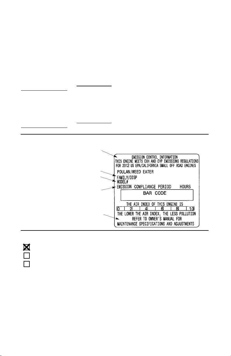
PIÈCES AJOUTÉES OU MODIFIÉES : L’utilisation de pièces ajoutées ou modifiées peut
constituer une raison d’annulation de réclamation en vertu de la garantie. Husqvarna
Consumer Outdoor Products N.A., Inc., n’est
pas responsable de couvrir les pannes de
pièces sous garantie occasionnées par l’utilisation de pièces ajoutées ou modifiées.
COMMENT REMPLIR UNE RÉCLAMATION : Si vous avez des questions sur vos
droits et vos responsabilités de garantie,vous
pouvez contacter votre centre de service le
plus proche, appeler Husqvarna Consumer
Outdoor Products N.A., Inc., aux Etats-Unis:
au numéro 1--800--487--5951,au Canada: au
numéro 1--800--805--5523, emission.warranty
@HCOP--emission.com. OÙ OBTENIR LE
SERVICE EN VERTU DE LA GARANTIE :
Leservice oulesréparationsenvertu dela garantie sont offerts dans tous les centres de
service Husqvarna Consumer Outdoor
Products N.A., Inc. Appelez aux Etats-Unis:
au numéro 1--800--487--5951,au Canada: au
numéro 1--800--805--5523, emission.warranty
@HCOP--emission.com.
L’information sur l’étiquette du produit indique la norme de certification de votre moteur.
Example: (Année) EPA et/ou CALIFORNIA.
Renseignements importants sur le
moteur. Ce moteur se forme aux
règlements sur les émissions pour
petits moteurs tout--terrain
Famille
NoDe Série
ENTRETIEN, REMPLACEMENT OU RÉPARATION DE PIÈCES RELATIVES À
L’ÉMISSION : Toute pièce de remplacement
approuvée Husqvarna Consumer Outdoor
Products N.A., Inc., utilisée dans l’accomplissement de tout entretien ou réparation en
vertu de la garantie sur les pièces relatives à
l’émission sera fournie gratuitement au propriétaire si cette pièce est sous garantie.
LISTE DES PIÈCES GARANTIES RELATIVESAU CONTRÔLE DES ÉMISSIONS :
Carburateur, filtre à air (couverte jusqu’à la
date de remplacement pour l’entretien),
système d’allumage: bougie (couverte jusqu’à la date de remplacement pour l’entretien), module d’allumage, silencieux incluant
le catalyseur (si équipé), réservoir de carburant, tuyau de carburant, et capuchon de remplissage. DÉCLARATION D’ENTRETIEN :
Le propriétaire est responsable d’effectuer
tout l’entretien requis tel qu’indiqué dans le
manuel d’instructions.
Heures de longévité du moteur
Consultez le manuel d’instructions
pour les caractéristiques et les
réglages d’entretien
Ce moteur est certifié se conformer aux règles d’émissions pour les usages suivants :
Modéré (50 heures)
Intermédiaire (125 heures)
Étendu (300 heures)
51

52
 Loading...