

Page 1

CLS200
User’s Guide
Page 2

CLS200 Series User’s Guide
Safety Warnings, Cautions, and Notes
WARNING! The controller may fail in a 0% or 100% power
output state. To prevent death, personal injury, equipment
damage or property damage, install external safety shutdown
devices. If death or injury may occur, you must install approved
safety shutdown devices that operate independently from the
process control equipment.
WARNING! Risk of electric shock. Shut off power to your entire
process before you begin installation of the controller.
WARNING! To reduce the risk of fire or electric shock, install
the CLS200 in a controlled environment, relatively free of
contaminants.
WARNING! To reduce the risk of electrical shock, fire, and
equipment damage, follow all local and national electrical codes.
Correct wire sizes, fuses and thermal breakers are essential for
safe operation of this equipment.
WARNING! Use a power supply with a Class 2 rating only. UL®
approval requires a Class 2 power supply.
WARNING! During autotuning, the controller will set the output
to 100% until the process variable rises near the setpoint. Set
the setpoint within the safe operating limits of your system.
WARNING! Do not rely solely on the output override feature to
shut down your process. Install external safety devices or overtemperature devices for emergency shutdowns.
WARNING! Do not rely solely on the sensor fail alarm to adjust
the output in the event of a sensor failure. If the loop is in manual
control when a failed sensor alarm occurs, the output is not
adjusted. Install independent external safety devices that will
shut down the system if a failure occurs.
CAUTION! Never run input leads in bundles with high power
wires or near other sources of EMI. This could inductively couple
voltage onto the input leads and damage the controller or could
induce noise and cause poor measurement and control.
Physically separate high-voltage circuits from low-voltage circuits
and from CLS200 hardware. If possible, install high-voltage ac
power circuits in a separate panel.
CAUTION! Without proper grounding, the CLS200 may not
operate properly or may be damaged.
CAUTION! To prevent damage from incorrect connections, do
not turn on the ac power before testing the connections.
CAUTION! The EPROM and other components are sensitive
to damage from electrostatic discharge (ESD). To prevent ESD
damage, use an ESD wrist strap or another antistatic device.
NOTE! For indoor use only.
Avertissements, Attentions et Remarques
AVERTISSEMENT! Le régulateur peut s’avérer défaillant avec
un régime de puissance de sortie à 0 % ou à 100 %. Pour éviter
tout risque de décès, blessure personnelle, endommagements
de l’équipement ou dégâts matériels, veuillez installer des
équipements d’arrêt d’urgence externes. Si un décès ou
un accident venait à se produire, vous devez installer des
équipements d’arrêt d’urgence approuvés qui fonctionnent
indépendamment du matériel de contrôle du processus.
AVERTISSEMENT! Risques de choc électrique. Coupez le
courant de votre processus tout entier avant de commencer à
installer le régulateur.
AVERTISSEMENT! Afin de minimiser les risques d’incendie ou
de choc électrique, installez le CLS200 dans un environnement
sous contrôle et relativement épargné par les contaminants.
AVERTISSEMENT! Afin de minimiser les risques de choc
électrique, d’incendie, et de dégâts matériels, suivez tous les
codes de l’électricité locaux et nationaux. Des diamètres de fils,
des fusibles et des disjoncteurs magnéto-thermiques adaptés
sont indispensables pour un fonctionnement sécurisé de cet
équipement.
AVERTISSEMENT! Utilisez uniquement une alimentation
électrique avec une note de rang 2. Une approbation UL®
impose une alimentation électrique de rang 2.
AVERTISSEMENT! Pendant le réglage automatique, le
régulateur définira la sortie sur 100 % jusqu’à ce que la variable
du processus s’élève près de la valeur seuil. Définissez la valeur
seuil dans les limites de fonctionnement sécurisées de votre
système.
AVERTISSEMENT! Ne comptez pas uniquement sur la fonction
de priorité de sortie pour arrêter le processus. Installez les
dispositifs de sécurité externes ou de protection contre l’excès
de température pour les arrêts d’urgence.
AVERTISSEMENT! Ne comptez pas uniquement sur l’alarme
d’échec du capteur pour ajuster la sortie dans l’éventualité
d’une défaillance du capteur. Si la boucle est en contrôle manuel
lorsqu’une alarme d’échec du capteur se déclenche, la sortie
n’est pas ajustée. Installez des dispositifs externes indépendants
qui éteindront le système si une défaillance se produit.
ATTENTION! Ne faites jamais fonctionner des conducteurs
d’entrée en faisceau avec des câbles à haute puissance ou
près d’autres sources d’EMI. Cela pourrait lier par couplage
inductif la tension sur les conducteurs d’entrée et endommager
le régulateur, ou créer un bruit et être à l’origine de mauvaises
mesures et de régulations erronées.
Séparez physiquement les circuits haute-tension des circuits
basse-tension et du matériel CLS200. Si possible, installez des
circuits électriques ca haute-tension dans un panneau séparé.
2
Page 3

CLS200 Series User’s Guide
ATTENTION! Sans mise à la terre appropriée, il se peut que le
CLS200 ne fonctionne pas correctement ou soit endommagé.
ATTENTION! Pour éviter tout dommage causé par des
connexions incorrectes, n’allumez pas l’alimentation électrique
en ca avant d’avoir testé les connexions.
ATTENTION! L’EPROM et les autres composants sont sensibles
aux dégâts provoqués par les décharges électrostatiques (ESD).
Pour éviter de tels dommages, utilisez un bracelet antistatique
ou tout autre dispositif antistatique.
REMARQUE : Destiné à un usage intérieur uniquement.
Technical Assistance
If you encounter a problem with your Watlow® controller, review
your configuration information to verify that your selections are
consistent with your application: inputs, outputs, alarms, limits, etc.
If the problem persists, you can get technical assistance from your
local Watlow representative (see back cover), by e-mailing your
questions to wintechsupport@watlow.com or by dialing +1 (507)
494-5656 between 7 a.m. and 5 p.m. Central Time USA & Canada.
Ask for for an Applications Engineer. Please have the complete
model number available when calling.
Return Material Authorization (RMA)
1. Call Watlow Customer Service, (507) 454-5300, for a Return
Material Authorization (RMA) number before returning any
failed product to Watlow. If you do not know why the product
failed, contact an Application Engineer. All RMA’s require:
• Ship-to address
• Bill-to address
• Contact name
• Phone number
• Method of return shipment
• Your P.O. number
• Detailed description of the problem
• Any special instructions
• Name and phone number of person returning the
product
2. Prior approval and an RMA number from the customer
service department is required when returning any product.
Make sure the RMA number is on the outside of the
carton and on all paperwork returned. Ship on a freight
prepaid basis.
3. After we receive your return, we will examine it to verify the
reason for the product failure. Unless otherwise agreed to
in writing, Watlow’s standard warranty provisions, which can
be located at www.watlow.com/terms, will apply to any failed
product.
4. In the event that the product is not subject to an applicable
warranty, we will quote repair costs to you and request a
purchase order from you prior to proceeding with the
repair work.
5. Watlow reserves the right to charge for no trouble found
(NTF) returns.
Contact Watlow
1241 Bundy Boulevard
Winona, Minnesota 55987 USA
Phone: +1 (507) 454-5300
Fax: +1 (507) 452-4507
http://www.watlow.com
Warranty
This product is warranted by Watlow for a period of 36 months in
accordance with the terms and conditions set forth on Watlow’s
website, which may be accessed at www.watlow.com/terms.
Document
Document Number: 10-30466 Revision –
August 2019
©2019 Watlow Electric Manufacturing Company, all rights reserved. Watlow® is a registered trademark of Watlow Electric and Manufacturing
Company. Modbus® is a registered trademark of Schneider Automation Incorporated. UL® is a registered trademark of Underwriter’s
Laboratories, Inc. Windows® is a registered trademark of Microsoft Corporation.
3
Page 4

Table of Contents
Chapter 1: System Overview—12
Manual Contents 12
Getting Started 13
Safety Symbols 13
Initial Inspection 13
Product Features 13
CLS200 Parts List 15
CLS200 16
TB50 17
CLS200 Cabling 18
External Safety Devices 18
Power-Fail Protection 18
Chapter 2: Installation—19
Typical Installation 19
Mounting Controller Components 20
Recommended Tools 20
Mounting the Controller 21
Mounting the TB50 23
Mounting the Power Supply 25
System Wiring 25
Wiring Recommendations 26
Noise Suppression 26
Ground Loops 28
Power Connections 29
Wiring the Power Supply 29
Connecting TB50 to CLS200 31
Testing Your System 31
TB50 or TB18 Test 31
Digital Output Test 31
Digital Input Test 31
Sensor Wiring 32
Input Wiring Recommendations 33
Thermocouple Connections 33
RTD Input Connections 34
Reference Voltage Terminals 34
Voltage Input Connections 34
Current Input Connections 35
Pulse Input Connections 35
Wiring Control and Digital I/O 36
Output Wiring Recommendations 36
Cable Tie Wraps 37
Digital Outputs 37
Digital Inputs 40
TB18 Connections 41
TB50 Connections 42
Analog Outputs 44
Wiring the Dual DAC 44
Wiring the Serial DAC 44
Serial Communications 44
EIA/TIA-232 Interface 44
EIA/TIA-485 Interface 46
EIA/TIA-485 Converters and Laptop
Computers 47
Chapter 3: Using CLS200—48
Front Panel 49
Front Panel Keys 49
Displays 51
Bar Graph Display 51
Single Loop Display 52
Alarm Displays 53
System Alarms 55
Job Display 55
Changing the Setpoint 56
Selecting the Control Status 56
Manual and Automatic Control 57
Autotuning a Loop 57
Using Alarms 59
Alarm Delay 59
Failed Sensor Alarms 59
Process Alarms 61
Global Alarm 63
Ramp/Soak 63
Chapter 4: Setup—64
How to Access the Setup Menus 64
How to Change a Parameter 64
Standard Menus 66
Setup Global Parameters Menu 67
Load Setup From Job 67
Save Setup to Job 68
Job Select Digital Inputs 68
Job Select Digital Inputs Active 69
Output Override Digital Input 70
Override Digital Input Active 70
Startup Alarm Delay 70
Keyboard Lock Status 71
4
Page 5

CLS200 Series User’s Guide
Power Up Output Status 71
Process Power Digital Input 71
Controller Address 72
Communications Baud Rate 72
Communications Protocol 72
Communications Error Checking 72
AC Line Frequency 73
Digital Output Polarity on Alarm 73
EPROM Information 73
Setup Loop Input Menu 74
Input Type 75
Loop Name 76
Input Units 76
Input Reading Offset 76
Reversed T/C Detection 77
Input Pulse Sample Time 77
Linear Scaling Parameters 77
Input Filter 80
Setup Loop Control Parameters Menu 81
Heat or Cool Control PB 82
Heat or Cool Control TI 82
Heat or Cool Control TD 82
Heat or Cool Output Filter 83
Spread 83
Restore PID Digital Input 83
Setup Loop Outputs Menu 84
Enable or Disable Heat or Cool Outputs 85
Heat or Cool Output Type 85
Heat or Cool Cycle Time 86
SDAC Mode 86
SDAC Low Value 86
SDAC High Value 86
Heat or Cool Output Action 87
Heat or Cool Output Limit 87
Heat or Cool Output Limit Time 87
Sensor Fail Heat or Cool Output 88
Heat or Cool Thermocouple Break Output
Average 88
Heat or Cool Linearity 88
Setup Loop Alarms Menu 89
High Process Alarm Setpoint 90
High Process Alarm Type 90
High Process Alarm Output Number 90
Deviation Alarm Value 91
High Deviation Alarm Type 91
High Deviation Alarm Output Number 91
Low Deviation Alarm Type 91
Low Deviation Alarm Output Number 92
Low Process Alarm Setpoint 92
Low Process Alarm Type 92
Low Process Alarm Output Number 92
Alarm Deadband 92
Alarm Delay 93
Manual I/O Test 93
Digital Inputs 94
Test Digital Output 94
Digital Output Number 94
Keypad Test 95
Display Test 95
Chapter 5: Enhanced Features—96
Enhanced Features Menus 97
Process Variable Retransmit 98
Process Variable Retransmit Menu 98
Process Variable Retransmit Example: Data
Logging 100
Cascade Control 102
Setup Loop Cascade Menu 103
Cascade Control Example: Water Tank 105
Ratio Control 108
Setup Loop Ratio Control Menu 108
Ratio Control Example: Diluting KOH 110
Remote Analog Setpoint 112
Remote Analog Setpoint Example: Setting a
Setpoint with a PLC 112
Differential Control 113
Differential Control Example:
Thermoforming 113
Chapter 6: Ramp/Soak—115
Features 116
Ramp/Soak Menus 117
Setup Global Parameters Menu 118
Ramp/Soak Time Base 118
Setup Ramp/Soak Profile Menu 118
Edit Ramp/Soak Profile 118
Copy Setup From Profile 118
Tolerance Alarm Time 119
Ready Segment Setpoint 119
Ready Segment Edit Events 119
External Reset Input Number 120
Edit Segment Number 120
Segment Time 120
Segment Setpoint 121
Edit Segment Events 121
Edit Segment Triggers 122
Segment Tolerance 123
Last Segment 124
Repeat Cycles 124
Setpoints and Tolerances for Various Input
Types 124
Using Ramp/Soak 125
Ramp/Soak Displays 125
Assigning a Profile to a Loop 127
Running a Profile 128
Holding a Profile or Continuing from Hold 128
Responding to a Tolerance Alarm 129
Resetting a Profile 130
In Case of a Power Failure 130
5
Page 6

CLS200 Series User’s Guide
Chapter 7: Turning and Control—131
Control Algorithms 131
On/Off Control 131
Proportional Control 132
Proportional and Integral Control 133
Proportional, Integral and Derivative
Control 133
Heat and Cool Outputs 134
Control Outputs 134
Output Control Signals 134
Output Filter 135
Reverse and Direct Action 135
Setting Up and Tuning PID Loops 136
Proportional Band (PB) Settings 136
Integral Settings 136
Derivative Settings 137
General PID Constants by Application 138
Proportional Band Only (P) 138
Proportional with Integral (PI) 138
PI with Derivative (PID) 138
Chapter 8: Troubleshooting and
Reconfiguring—139
When There is a Problem 139
Troubleshooting Controllers 140
Process and Deviation Alarms 140
Failed Sensor Alarms 141
System Alarms 142
Other Behaviors 142
Corrective and Diagnostic Procedures 143
Low Power 143
Battery Dead 143
Ambient Warning 144
H/W Ambient Failure 144
H/W Gain or Offset Failure 145
Keys Do Not Respond 145
Checking Analog Inputs 145
Earth Grounding 146
Checking Control Outputs 147
Testing Control Output Devices 147
Testing the TB18 and TB50 147
Testing Control and Digital Outputs 147
Testing Digital Inputs 148
Additional Troubleshooting for Computer
Supervised Systems 148
Computer Problems 148
Communications 149
Ground Loops 149
Software Problems 149
NO-Key Reset 150
Replacing the EPROM 150
Removing or Replacing the Battery 152
Changing Communications 153
Scaling Resistors 154
Four-Loop and Eight-Loop Input Circuit 154
Current Inputs to Four-Loop and Eight-Loop
Controllers 155
Voltage Inputs to Four-Loop and Eight-Loop
Controllers 155
RTDs and Thermistor Inputs to Four-Loop and
Eight-Loop Controllers 156
Sixteen-Loop Input Circuit 157
Current Inputs to Sixteen-Loop Controllers 157
Voltage Inputs to Sixteen-Loop Controllers 158
Scaling and Calibration 158
Chapter 9: Linear Scaling Examples—159
Example 1: A 4-to-20mA Sensor 159
Situation 159
Setup 159
Example 2: A 0-to-5VDC Sensor 160
Situation 160
Setup 160
Example 3: A Pulse Encoder 161
Situation 161
Setup 161
Chapter 10: Specifications—162
CLS200 System Specifications 162
CLS200 Processor Physical Specifications 162
TB50 Physical Specifications 164
Inputs 166
Outputs 168
Glossary—171
Index—180
Menu Structure—192
Declaration of Conformity—193
How to Reach Us—194
6
Page 7

List of Figures
Chapter 1: System Overview—12
Figure 1.1 — CLS200 Rear Views 16
Figure 1.2 — CLS200 Front Panel 17
Figure 1.3 — TB50 17
Chapter 2: Installation—19
Figure 2.1 — CLS200 System Components 20
Figure 2.2 —Clearance with TB18 Option 21
Figure 2.3 —Clearance with Standard SCSI Cable 21
Figure 2.3a — Clearance with Right-Angle SCSI Cable 22
Figure 2.4 —Mounting Bracket Clearance 22
Figure 2.5 —Panel Thickness and Cutout Size 22
Figure 2.6 — Mounting the TB50 23
Figure 2.7 — TB50 Mounted on a DIN Rail (Front) 24
Figure 2.8 — TB50 Mounted on DIN Rail (Side) 24
Figure 2.9 — Mounting a TB50 with Standoffs 25
Figure 2.10 — CLS200 Series Controller with TB18 29
Figure 2.11 — CLS200 Series Controller with TB50 29
Figure 2.12 — Power Connections 30
Figure 2.13 — Thermocouple Connections 33
Figure 2.14 — RTD Connections 34
Figure 2.15 — Linear Voltage Signal Connections 35
Figure 2.16 — Linear Current Signal Connections 35
Figure 2.17 — Encoder with 5VDC TTL Signa 36
Figure 2.18 — Encoder Input with Voltage Divider 36
Figure 2.19 — Digital Output Wiring 38
Figure 2.20 — S ample Heat, Cool and Alarm Output Connections 39
Figure 2.21 — Output Connections Using External Power Supply 39
Figure 2.22 — TB50 Watchdog Timer Output 39
Figure 2.23 — TB18 Watchdog Timer Output 40
Figure 2.24 — Wiring Digital Inputs 41
Figure 2.25 — Connecting One CLS200 to a Computer Using EIA/TIA-232 45
Figure 2.26 — EIA/TIA-485 Wiring 46
Figure 2.27 — Recommended System Connections 47
Chapter 3: Using CLS200—48
Figure 3.1 — Operator Displays 48
Figure 3.2 — CLS200 Front Panel 49
Figure 3.3 — Bar Graph Display 51
Figure 3.4 — Single Loop Display 52
Figure 3.5 — Single Loop Display, Heat and Cool Outputs Enabled 53
Figure 3.6 — Single Loop Display with a Process Alarm 53
7
Page 8

CLS200 Series User’s Guide
Figure 3.7 — Failed Sensor Alarm in the Single Loop Display 54
Figure 3.8 — Alarm Symbols in the Bar Graph Display 54
Figure 3.9 — Activation and Deactivation of Process Alarms 62
Chapter 4: Setup—64
Figure 4.1 — CLS200 Menu Tree 66
Figure 4.2 — Two Points Determine Process Variable Conversion 78
Figure 4.3 — Process Variable Limited by Input Reading Range 78
Figure 4.4 — Linear and Nonlinear Outputs 89
Figure 4.5 — Digital Inputs Screen 94
Chapter 5: Enhanced Features—96
Figure 5.1 — Enhanced Features Option Menus 97
Figure 5.2 — Linear Scaling of Process Variable for Retransmit 100
Figure 5.3 — Application Using Process Variable Retransmit 101
Figure 5.4 — Relationship Between the Primary Loop’s Output and the Secondary Loop’s Setpoint 103
Figure 5.5 — Application Using Cascade Control 105
Figure 5.6 — Secondary Loop Setpoint Related to Primary Loop Output 107
Figure 5.7 — Relationship Between the Master Loop’s Process Variable and the Ratio Loop’s Setpoint 108
Figure 5.8 — Application Using Ratio Control 110
Chapter 6: Ramp/Soak—115
Figure 6.1 — Sample Ramp/Soak Profile 115
Figure 6.2 — Setup Ramp/Soak Profiles Menu 117
Figure 6.3 — Positive and Negative Tolerances 123
Figure 6.4 — Ramp/Soak Screens 125
Chapter 7: Turning and Control—131
Figure 7.1 — On/Off Control 132
Figure 7.2 — Proportional Control 132
Figure 7.3 — Proportional and Integral Control 133
Figure 7.4 — Proportional, Integral and Derivative Control 133
Figure 7.5 — Time Proportioning and Distributed Zero Crossing Waveforms 134
Chapter 8: Troubleshooting and Reconfiguring—139
Figure 8.1 — Remove Board Assembly from Case 151
Figure 8.2 — Disconnect Keypad Ribbon Cable from Processor Board 151
Figure 8.3 — Unlatch Boards from Carrier 151
Figure 8.4 — Remove the Standoffs 151
Figure 8.5 — EPROM Location 152
Figure 8.6 — Remove EPROM 152
Figure 8.7 — Battery-Backed RAM Module on the Processor Board 153
Figure 8.8 — Jumper Configurations 153
Figure 8.9 — Differential Input Circuit in Four-Loop and Eight-Loop Controllers 154
Figure 8.10 — Single-Ended Input Circuit in Sixteen-Loop Controllers 157
Chapter 10: Specifications—162
Figure 10.1 — CLS200 Processor Module Dimensions 163
Figure 10.2 — CLS200 Clearances with Straight SCSI Cable 163
Figure 10.3 — CLS200 Clearances with Right-Angle SCSI Cable 164
Figure 10.4 — TB50 Dimensions 165
Figure 10.5 — TB50 Dimensions with Standard SCSI Cable 165
Figure 10.6 — TB50 Dimensions with Right-Angle SCSI Cable 166
8
Page 9

List of Tables
Chapter 1: System Overview—12
Table 1.1 — Ordering Options 15
Chapter 2: Installation—19
Table 2.1 — Cable Recommendations 26
Table 2.2 — Power Connections 29
Table 2.3 — Analog Input Connections on TB1 for Four-Loop and Eight-Loop Models 32
Table 2.4 — Analog Input Connections on TB1 for Sixteen-Loop Models 32
Table 2.5 — Digital Output States and Values Stored in the Controller 37
Table 2.6 — Digital Inputs States and Values Stored in the Controller 40
Table 2.7 — TB18 Connections 41
Table 2.8 — TB50 Connections for Four-Loop and Eight-Loop Controllers 42
Table 2.9 — TB50 Connections for Sixteen-Loop Controllers 43
Table 2.10 — EIA/TIA-232 Connections 45
Table 2.11 — RTS/CTS Pins in DB-9 and DB-25 Connectors 45
Chapter 3: Using CLS200—48
Table 3.1 — Bar Graph Display Symbols 51
Table 3.2 — Control Status Symbols on the Bar Graph and Single Loop Displays 52
Table 3.3 — Alarm Type and Symbols 54
Chapter 4: Setup—64
Table 4.1 — Global Parameters 67
Table 4.2 — Job Select Inputs 69
Table 4.3 — Job Selected for Various Input States 69
Table 4.4 — Firmware Option Codes 74
Table 4.5 — Setup Loop Input 74
Table 4.6 — CLS200 Input Types and Ranges 75
Table 4.7 — Input Character Sets 76
Table 4.8 — Input Reading Offset 77
Table 4.9 — Display Formats 79
Table 4.10 — Setup Loop Control Parameters 81
Table 4.11 — Setup Loop Outputs 84
Table 4.12 — Heat / Cool Output Types 85
Table 4.13 — Setup Loop Alarms 90
Table 4.14 — Manual I/O Test 93
Chapter 5: Enhanced Features—96
Table 5.1 — Application Example: Setting Up Process Variable Retransmit 101
Table 5.2 — Application Example: Setting Up Cascade Control 106
Table 5.3 — Application Example: Setting Up Ratio Control 111
9
Page 10

CLS200 Series User’s Guide
Table 5.4 — Application Example: Setting Up Remote Setpoint 112
Table 5.5 — Application Example: Setting Up Differential Control 114
Chapter 6: Ramp/Soak—115
Table 6.1 — Ramp/Soak Specifications 116
Table 6.2 — Trigger Latch Logic 123
Table 6.3 — Display Formats 124
Table 6.4 — Ramp/Soak Single Loop Display 125
Table 6.5 — Ramp/Soak Control Status Symbols 126
Table 6.6 — Ramp/Soak Profile Modes 129
Chapter 7: Turning and Control—131
Table 7.1 — Proportional Band Settings 136
Table 7.2 — Integral Term and Reset Settings 137
Table 7.3 — Derivative Term Versus Rate 137
Table 7.4 — General PID Constants 138
Chapter 8: Troubleshooting and Reconfiguring—139
Table 8.1 — Controller Alarm Codes for Process and Deviation Alarms 140
Table 8.2 — Operator Response to Alarms 141
Table 8.3 — Failed Sensor Alarm Codes 141
Table 8.4 — Hardware Error Messages 142
Table 8.5 — Other Symptoms 142
Table 8.6 — Resistor Values for Current Inputs to Four-Loop and Eight-Loop Controllers 155
Table 8.7 — Resistor Locations for Current Inputs to Four-Loop and Eight-Loop Controllers 155
Table 8.8 — Resistor Values for Voltage Inputs to Four-Loop and Eight-Loop Controllers 155
Table 8.9 — Resistor Locations for Voltage Inputs to Four-Loop and Eight-Loop Controllers 156
Table 8.10 — Resistor Values for RTD and Thermistor Inputs to Four-Loop and Eight-Loop Controllers 156
Table 8.11 — Resistor Locations for RTD and Thermistor Inputs to Four-Loop and Eight-Loop Controllers 156
Table 8.12 — Resistor Values for Current Inputs to Sixteen-Loop Controllers 157
Table 8.13 — Resistor Locations for Current Inputs to Sixteen-Loop Controllers 157
Table 8.14 — Resistor Values for Voltage Inputs to Sixteen-Loop Controllers 158
Table 8.15 — Resistor Locations for Voltage Inputs to Sixteen-Loop Controllers 158
Chapter 9: Linear Scaling Examples—159
Table 9.1 — Input Readings 159
Table 9.2 — Scaling Values 159
Table 9.3 — Input Readings and Calculations 160
Table 9.4 — Scaling Values 160
Table 9.5 — Scaling Values 161
Chapter 10: Specifications—162
Table 10.1 — Agency Approvals / Compliance 162
Table 10.2 — Environmental Specifications 162
Table 10.3 — Physical Dimensions 162
Table 10.4 — Processor with Standard SCSI Cable 163
Table 10.5 — Processor with Right Angle SCSI Cable 163
Table 10.6 — Processor Connections 164
Table 10.7 — TB50 Physical Dimensions 164
Table 10.8 — TB50 Connections 165
Table 10.9 — TB50 with Straight SCSI Cable 165
Table 10.10 — TB50 with Right Angle SCSI Cable 166
Table 10.11 — Analog Inputs 166
10
Page 11

CLS200 Series User’s Guide
Table 10.12 — Pulse Inputs 167
Table 10.13 — Thermocouple Range and Resolution 167
Table 10.14 — RTD Range and Resolution 168
Table 10.15 — Input Resistance for Voltage Inputs 168
Table 10.16 — Digital Inputs 168
Table 10.17 — Digital Outputs Control / Alarm 169
Table 10.18 — CPU Watchdog Output 169
Table 10.19 — 5VDC Output (Power to Operate Solid-State Relays) 169
Table 10.20 — Reference Voltage Output (Power to Operate Bridge Circuit Sensors) 170
Table 10.21 —Serial Communication 170
Table 10.22 — Power Requirements 170
11
Page 12

Chapter 1: System Overview
Manual Contents
This manual describes how to install, set up, and operate CLS200 controllers. Each chapter covers
a different aspect of your control system and may apply to different users:
• Chapter 1: System Overview provides a component list and summary of features for the
CLS200 series controllers.
• Chapter 2: Installation provides detailed instructions on installing the CLS200 series
controller and its peripherals.
• Chapter 3: Using CLS200 provides an overview of operator displays used for system
monitoring and job selection.
• Chapter 4: Setup provides detailed descriptions of all menus and parameters for controller
setup.
• Chapter 5: Enhanced Features describes process variable retransmit, ratio, differential and
cascade control features available with the enhanced features option.
• Chapter 6: Ramp/Soak explains how to set up and use the features of the ramp/soak
option.
• Chapter 7: Turning and Control describes available control algorithms and provides
suggestions for applications.
• Chapter 8: Troubleshooting and Reconfiguring includes troubleshooting, upgrading and
reconfiguring procedures for technical personnel.
• Chapter 9: Linear Scaling Examples provides an example configuring a pressure sensor, a
flow sensor, and an encoder using linear scaling.
• Chapter 10: Specifications lists detailed specifications of the controller and optional
components.
12
Page 13
CLS200 Series User’s Guide
Chapter 1: System Overview
Getting Started
The following sections provide information regarding product features, technical descriptions, safety
requirements, and preparation for operation.
Safety Symbols
These symbols are used throughout this manual:
NOTE! Marks a short message to alert you to an important detail.
CAUTION! Information that is important for protecting your equipment and
performance. Be especially careful to read and follow all cautions that apply to your
application.
WARNING! Safety alert appears with information that is important for protecting you,
others and equipment from damage. Pay very close attention to all warnings that apply
to your application.
Initial Inspection
Accessories may or may not be shipped in the same container as the CLS200, depending upon
their size. Check the shipping invoice carefully against the contents received in all boxes.
Product Features
The CLS200 series controllers provide 4, 8 or 16 fully independent control loops. When used as
a stand-alone controller, you may operate the CLS200 via the two-line 16-character display and
touch keypad. You can also use it as the key element in a computer-supervised data acquisition and
control system; the CLS200 can be locally or remotely controlled via an EIA/TIA-232 or EIA/TIA-485
serial communications interface.
The CLS200 features include:
• Direct Connection of Mixed Thermocouple Sensors: Connect most thermocouples
to the controller with no hardware modifications. Thermocouple inputs feature reference
junction compensation, linearization, process variable offset calibration to correct for sensor
inaccuracies, detection of broken, shorted or reversed thermocouples, and a choice of
Fahrenheit or Celsius display.
• Accepts Resistive Temperature Detectors (RTDs): Use 3-wire, 100Ω, platinum,
0.00385-curve sensors with two choices for range and precision of measurements. (To use
this input, order a four-loop or eight-loop controller with scaling resistors.)
• Automatic Scaling for Linear Analog Inputs: The CLS200 series automatically scales
linear inputs used with industrial process sensors. Enter two points, and all input values are
automatically scaled in your units. Scaling resistors must be installed.
• Dual Outputs: The CLS200 series includes both heat and cool control outputs for each
loop. Independent control parameters are provided for each output.
13
Page 14

CLS200 Series User’s Guide
Chapter 1: System Overview
• Independently Selectable Control and Output Modes: You can set each control output
to on/off, time proportioning, Serial DAC (digital-to-analog converter), or distributed zero
crossing mode. Set up to two outputs per loop for on/off, P, PI or PID control with reverse or
direct action.
• Control Outputs: Set high/low deviation and high/ low process limits to operate digital
outputs as on/off control functions or alarms.
• Flexible Alarm Outputs: Independently set high/ low process alarms and a high/low
deviation band alarm for each loop. Alarms can activate a digital output by themselves, or
they can be grouped with other alarms to activate an output.
• Global Alarm Output: When any alarm is triggered, the global alarm output is also triggered,
and it stays on until you acknowledge it.
• CPU Watchdog: The CLS200 series CPU watchdog timer output notifies you of system
failure. Use it to hold a relay closed while the controller is running, so you are notified if the
microprocessor shuts down.
• Front Panel or Computer Operation: Set up and run the controller from the front panel or
from a local or remote computer. Watlow® offers SpecView, a Windows® compatible Human
Machine Interface (HMI) software package that includes data logging and graphing features in
addition to process monitoring.
• Modbus® RTU Protocol, EIA/TIA-232 and 485 Communications: Connect to PLCs,
operator interface terminals and third-party software packages using the widely supported
Modbus® RTU protocol.
• Multiple Job Storage: Store up to eight jobs in memory, and access them locally by
entering a single job number or remotely via digital inputs. Each job is a set of operating
conditions, including setpoints and alarms.
• Nonlinear Output Curves: Select either of two non-linear output curves for each control
output.
• Autotuning: Use the autotune feature to set up your system quickly and easily.
• Pulse Counter Input: Use the pulse counter input for precise control of motor or belt speed.
• Low Power Shutdown: The controller shuts down and turns off all outputs when it detects
the input voltage drop below the minimum safe operating level.
14
Page 15

CLS200 Series User’s Guide
Chapter 1: System Overview
CLS200 Parts List
You may have received one or more of the following components. See Table 1.1 – Ordering Options
for configuration information.
• CLS200 series controller
• Controller mounting kit
• TB50 with 50-pin SCSI cable
• EIA/TIA-232 or EIA/TIA-485 communications cable
• Special input resistors (installed in CLS200)
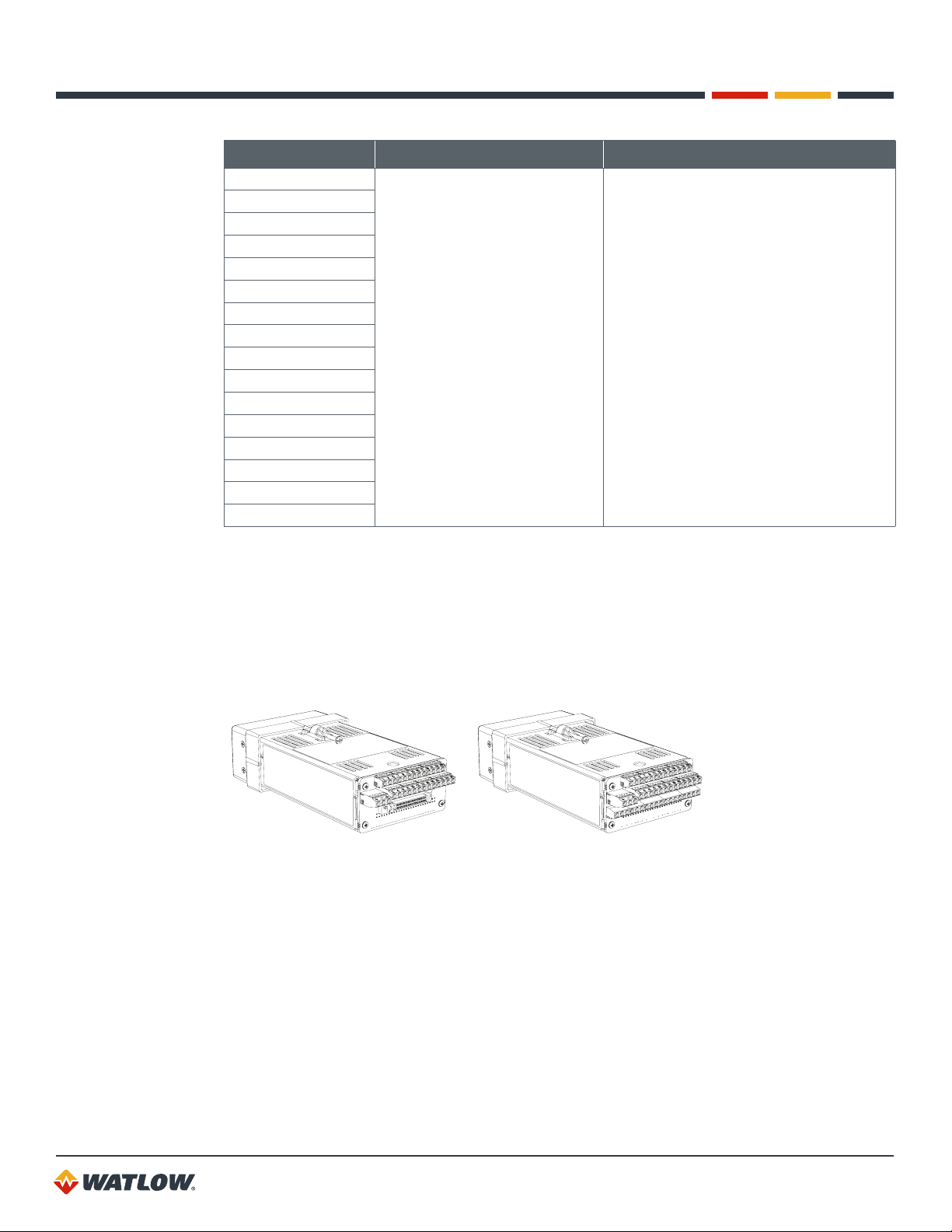
Table 1.1 — Ordering Options
CHARACTERISTIC OPTIONS DESCRIPTION
4 Loops
Number of Loops
Firmware
Digital I/O Termination
Digital I/O Termination
Board Accessory
Digital I/O Termination
Cable Accessory
Serial Communication
Jumper Settings
Serial Communication
Cable
Mounting Hardware
Customer Specific None Not applicable to standard product
8 Loops
16 Loops
Standard
Ramp and Soak
Enhanced Features
Screw Terminals (TB18) TB18 Terminal Block
Mass Termination (SCSI) SCSI Connector
None No external terminal board included
TB50 Terminal Board TB50-SCSI (50 Pin terminal board)
None
3-foot SCSI cable
6-foot SCSI cable
3-foot SCSI cable with right angle
connector
EIA/TIA-232
EIA/TIA-485, not terminated
EIA/TIA-485, terminated
None No communication cable
10 foot communication cable
(DB-9 female/bare wires)
Plastic collar and screw clips Standard mounting hardware
Low profile metal L-brackets and
screws
The number of analog inputs and control
loops that can be controlled based on the
feedback from the analog inputs. There is an
additional control loop that uses feedback
from the pulse input.
Includes closed-loop, PID control, autotune, alarms, job memory and failed sensor
detection
Provides the features of the standard version
plus the additional Ramp and Soak features
Provides the features of the standard version
plus the additional Enhanced Features
Accessory cable to connect digital I/O
signals between the SCSI connector on the
controller and the TB50 board
Application uses 232 communication or no
communication
Application uses 485 communication, this
controller is not last in the network
Application uses 485 communication, this
controller is last in the network
Cable for 232 communication
Mounting hardware for legacy applications
with tight fit
15
Page 16
CLS200 Series User’s Guide
Chapter 1: System Overview
CHARACTERISTIC OPTIONS DESCRIPTION
Analog Input 1 Options for all units:
Analog Input 2
Analog Input 3
Analog Input 4
Analog Input 5
Analog Input 6
Analog Input 7
Analog Input 8
Analog Input 9
Analog Input 10
Analog Input 11
Analog Input 12
Analog Input 13
Analog Input 14
Analog Input 15
Analog Input 16
• Standard (Thermocouples and
-10 to 60mV)
• Linear Current: 0-20mA DC /
4-20mA DC
• Linear Voltage: 0-5VDC
• Linear Voltage: 0-10VDC
Additional options for 4-loop and
8-loop units:
• 100 Ohm RTD Tenths Degree
• 100 Ohm RTD Whole Degree
Standard units accept thermocouples on
all inputs. Controllers can be equipped with
resistors to scale signals for various types
of sensors. These resistors must be factory
installed.
Sixteen loop controllers cannot accept RTD
sensors.
Technical Description
This section contains a technical description of each component of your CLS200 series controller.
CLS200
The CLS200 is housed in an 1/8-DIN panel mount package. It contains the CPU, RAM with a built-in
battery, EPROM, serial communications, digital I/O, analog inputs, the screen and touch keypad.
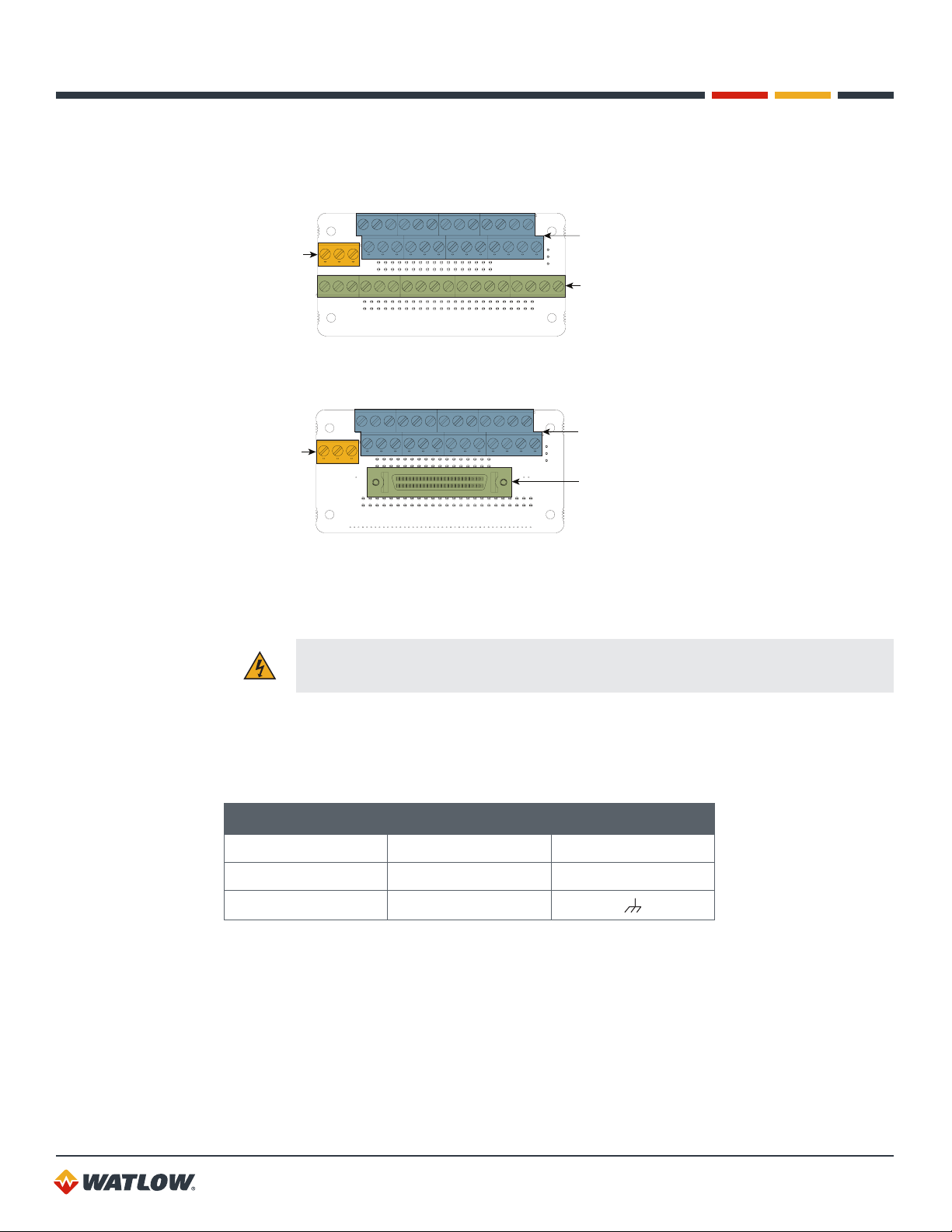
SCSI Digital I/O Option TB18 Digital I/O Option
Figure 1.1 — CLS200 Rear Views
The CLS200 has the following features:
• Keypad and 2-line, 16-character display.
• Screw terminals for the power and analog inputs and communications.
• Input power is 12 to 24VDC at 1 Amp.
• A 50-pin SCSI cable connects the digital inputs and outputs to the 50-terminal block (TB50).
Four-loop and eight-loop models are available with an 18-terminal block (TB18) in place of the
SCSI connector, as shown in Figure 1.2.
16
Page 17
CLS200 Series User’s Guide
Chapter 1: System Overview
The firmware resides in an EPROM. See Replacing the EPROM on page 150 for information on
removing and replacing the EPROM.
The operating parameters are stored in battery-backed RAM. If there is a power loss the operating
parameters are unchanged. The battery has a ten-year shelf life, and it is not used when the unit
is on.
The microprocessor performs all calculations for input signal linearization, PID control, alarms and
communications.
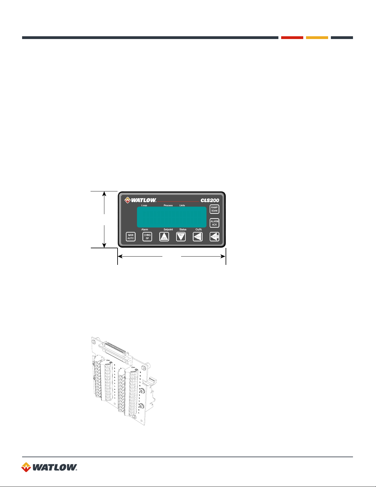
Front Panel Description
The display and touch keypad provide an intelligent way to operate the controller. The display has
16 alphanumeric or graphic characters per line. The 8-key keypad allows you to change the
operating parameters, controller functions, and displays.
The information-packed displays show process variables, setpoints, and output levels for each loop.
A bar graph display, single loop display, scanning display and an alarm display offer a real-time view
of process conditions. Two access levels allow operator changes and supervisor changes.
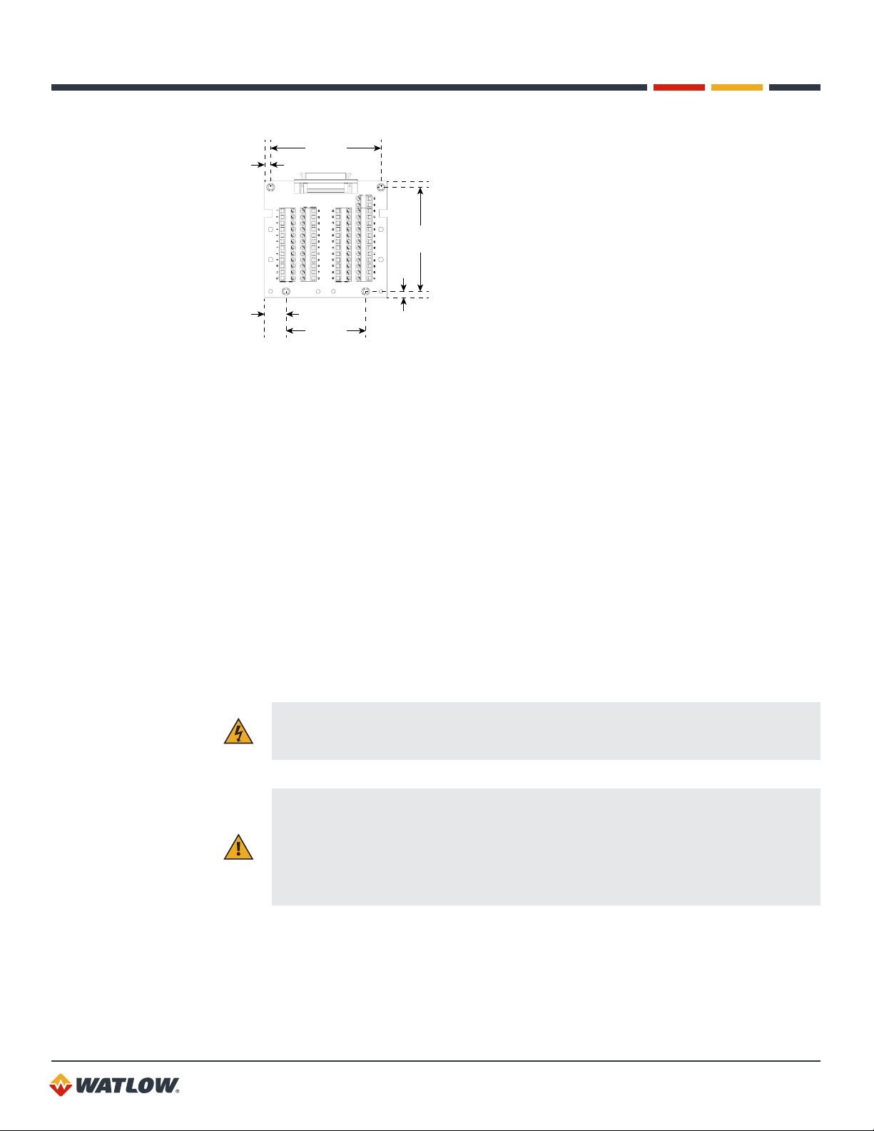
1.98 in.
(50 mm)
3.80 in.
(96 mm)
Figure 1.2 — CLS200 Front Panel
TB50
The TB50 is an optional screw-terminal interface for control wiring which allows you to connect
relays, encoders and discrete I/O devices to the CLS200. The screw terminal blocks accept wires as
large as 18 AWG (0.75 mm2). A 50-pin SCSI cable connects the TB50 to the CLS200.
Figure 1.3 — TB50
17
Page 18

CLS200 Series User’s Guide
Chapter 1: System Overview
CLS200 Cabling
Watlow offers optional cables to support installing your CLS200. A 50-pin SCSI cable connects the
TB50 to the CLS200.
The optional cable used to connect the CLS200 to a computer using EIA/TIA-232 communications
has a DB9 connector for the computer and bare wires for connecting to the CLS200.
Safety
Watlow has made every effort to ensure the reliability and safety of this product. In addition, we have
provided recommendations that will allow you to safely install and maintain this controller.
External Safety Devices
The CLS200 controller may fail full-on (100% output power) or full-off (0% output power), or may
remain full-on if an undetected sensor failure occurs. For more information about failed sensor
alarms, see Failed Sensor Alarms on page 59.
Design your system to be safe even if the controller sends a 0% or 100% output power signal at any
time. Install independent, external safety devices that will shut down the system if a failure occurs.
Typically, a shutdown device consists of an agency approved high/low process limit controller
that operates a shutdown device such as a mechanical contactor. The limit controller monitors
for a hazardous condition such as an undertemperature or over-temperature fault. If a hazardous
condition is detected, the limit controller sends a signal to open the contactor.
The safety shutdown device (limit controller and contactor) must be independent from the process
control equipment.
WARNING! The controller may fail in a 0% or 100% power output state. To prevent
death, personal injury, equipment damage or property damage, install external safety
shutdown devices. If death or injury may occur, you must install approved safety
shutdown devices that operate independently from the process control equipment.
With proper approval and installation, thermal fuses may be used in some processes.
Power-Fail Protection
In the occurrence of a sudden loss of power, this controller can be programmed to reset the control
outputs to off (this is the default). Typically, when power is re-started, the controller restarts to data
stored in memory. If you have programmed the controller to restart with control outputs on, the
memory-based restart might create an unsafe process condition for some installations. Therefore,
you should only set the restart with outputs on if you are certain your system will safely restart. (See
Process Power Digital Input on page 71.)
When using a computer or host device, you can program the software to automatically reload
desired operating constants or process values on power-up. Keep in mind that these convenience
features do not eliminate the need for independent safety devices.
Contact Watlow if you have any questions about system safety or system operation.
18
Page 19

Chapter 2: Installation
This chapter describes how to install the CLS200 series controller and its peripherals. Installation of
the controller involves the following procedures:
• Determining the best location for the controller
• Mounting the controller and TB50
• Power connection
• Input wiring
• Communications wiring (EIA/TIA-232 or EIA/TIA-485)
• Output wiring
WARNING! Risk of electric shock. Shut off power to your entire process before you
begin installation of the controller.
WARNING! The controller may fail in a 0% or 100% power output state. To prevent
death, personal injury, equipment damage or property damage, install external safety
shutdown devices. If failure may cause death or injury, you must install approved safety
shutdown devices that operate independently from the process control equipment.
Typical Installation
Figure 2.1 shows typical installations of the controller with the TB50 and the TB18 terminal blocks.
The type of terminal block you use greatly impacts the layout and wiring of your installation site. (See
Figures 2.2 to 2.11.)
We recommend that you read this entire chapter first before beginning the installation procedure.
This will help you to carefully plan and assess the installation.
19
Page 20
CLS200 Series User’s Guide
Chapter 2: Installation
CLS200 with SCSI Digital I/O
Sensor Inputs
SCSI Connector
CLS200 with TB18 Digital I/O
Sensor Inputs
TB18 allows connection to...
11 Outputs for Control & Alarms
2 Digital Inputs
1 Pulse Input
Figure 2.1 — CLS200 System Components
TB50 Accessory Board
SCSI Cable
TB50 allows connection to...
35 Outputs for Control & Alarms
8 Digital Inputs
1 Pulse Input
Mounting Controller Components
Install the controller in a location free from excessive heat (below 50ºC [122°F]), dust, and
unauthorized handling. Electromagnetic and radio frequency interference can induce noise on
sensor wiring. Select locations for the CLS200 and TB50 such that wiring can be routed clear of
sources of interference such as high voltage wires, power switching devices and motors.
NOTE! For indoor use only.
WARNING! To reduce the risk of fire or electric shock, install the CLS200 in a controlled
environment, relatively free of contaminants.
Recommended Tools
Use any of the following tools to cut a hole of the appropriate size in the panel.
• Jigsaw and metal file, for stainless steel and heavyweight panel doors.
• 1/8-DIN rectangular punch for most panel materials and thicknesses.
• Nibbler and metal file, for aluminum and lightweight panel doors.
20
Page 21
CLS200 Series User’s Guide
2.44 in.
Chapter 2: Installation
You will also need these tools:
• Phillips head screwdriver
• 1/8 in. (3 mm) flathead screwdriver for wiring
• Multimeter
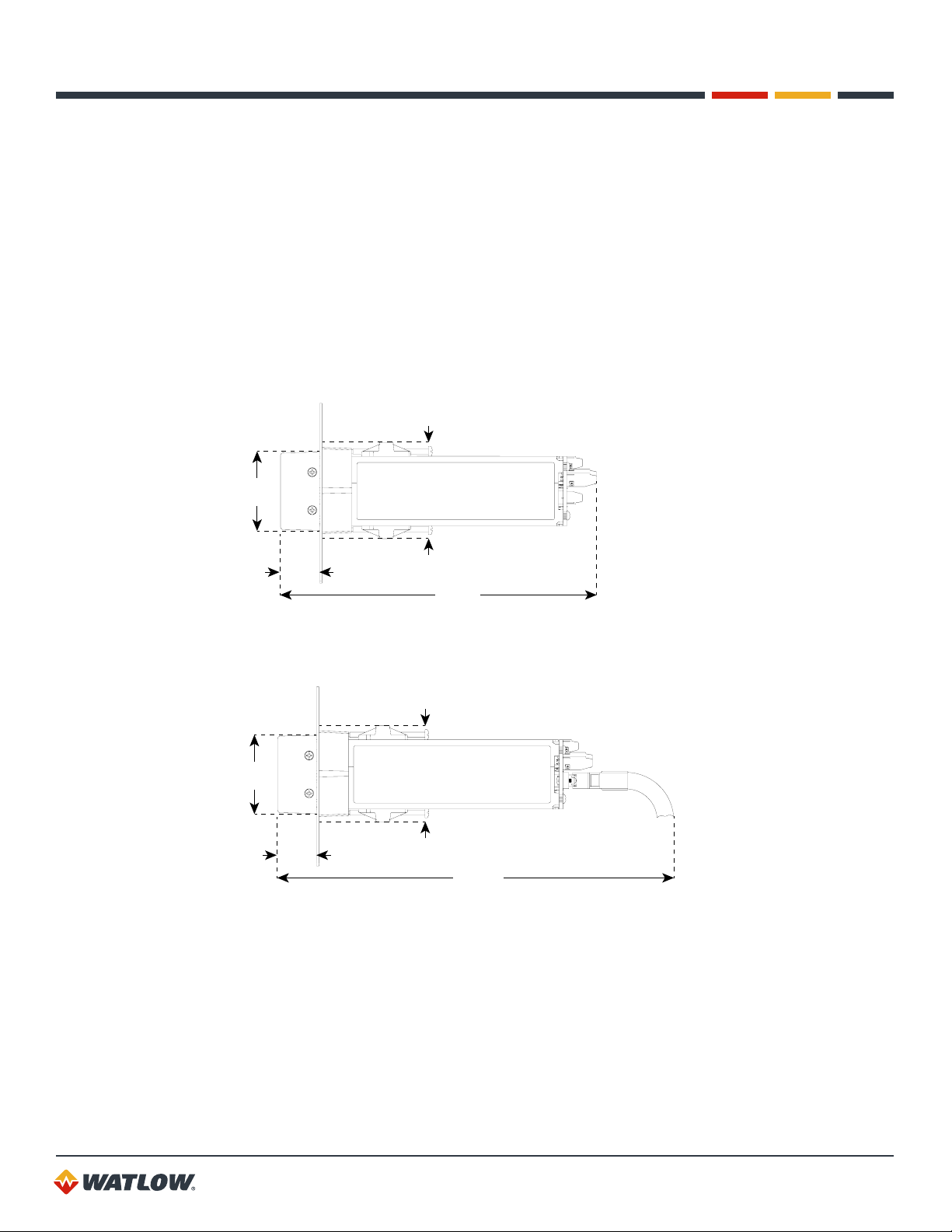
Mounting the Controller
Mount the controller before you mount the terminal block or do any wiring. The controller’s
placement affects placement and wiring considerations for the other components of your system.
Ensure there is enough clearance for mounting brackets, terminal blocks, and cable and wire
connections.
(62 mm)
1.98 in.
(50 mm)
1.00 in.
(25 mm)
Figure 2.2 —Clearance with TB18 Option
1.98 in.
(50 mm)
1.00 in.
(25 mm)
Figure 2.3 —Clearance with Standard SCSI Cable
8.00 in.
(203 mm)
2.44 in.
(62 mm)
10.00 in.
(254 mm)
21
Page 22
CLS200 Series User’s Guide
Chapter 2: Installation
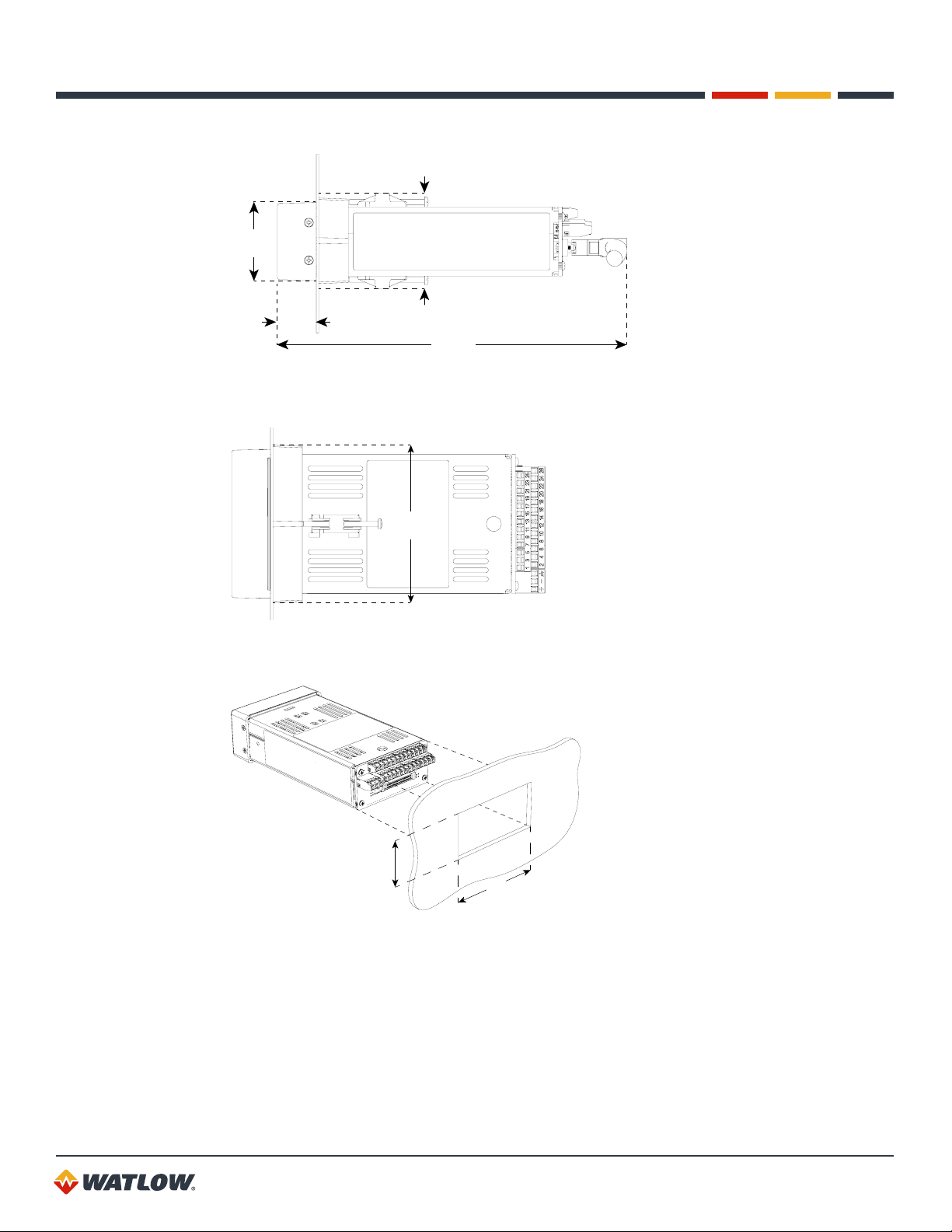
2.44 in.
(62 mm)
1.98 in.
(50 mm)
1.00 in.
(25 mm)
Figure 2.3a — Clearance with Right-Angle SCSI Cable
9.00 in.
(229 mm)
4.02 in.
(102 mm)
Figure 2.4 —Mounting Bracket Clearance
1.80 ± 0.020 in.
(45.7 ± 0.5 mm)
Figure 2.5 —Panel Thickness and Cutout Size
3.63 ± 0.020 in.
(92.2 ± 0.5 mm)
22
Page 23
CLS200 Series User’s Guide
Chapter 2: Installation
We recommend you mount the controller in a panel not more than 0.2 in. (5 mm) thick.
1. Choose a panel location free from excessive heat (below 50°C [122°F]), dust, and unauthorized
handling. (Make sure there is adequate clearance for the mounting hardware, terminal blocks,
and cables. The controller extends 7.00 in. (178 mm) behind the panel. Allow adequate room
for wiring and cables beyond the connectors.)
2. Temporarily cover slots in the metal housing so that dirt, metal filings, and pieces of wire do not
enter the housing and lodge in the electronics.
3. Cut a hole in the panel 1.80 in. (46 mm) by 3.63 in. (92 mm) as shown above. (Use caution; the
dimensions given here have 0.02 in. (0.5 mm) tolerances.
4. Remove the brackets and collar from the controller, if they are already in place.
5. Slide the controller into the panel cutout.
6. Slide the mounting collar over the back of the controller, making sure the mounting screw
indentations face toward the back of the controller.
7. Loosen the mounting bracket screws enough to allow for the mounting collar and panel
thickness. Place each mounting bracket into the mounting slots (head of the screw facing
the back of the controller). Push each bracket backward then to the side to secure it to the
controller’s case.
8. Make sure the controller is seated properly. Tighten the installation screws firmly against the
collar to secure the unit. Ensure that the end of the mounting screws fit into the indentations on
the mounting collar.
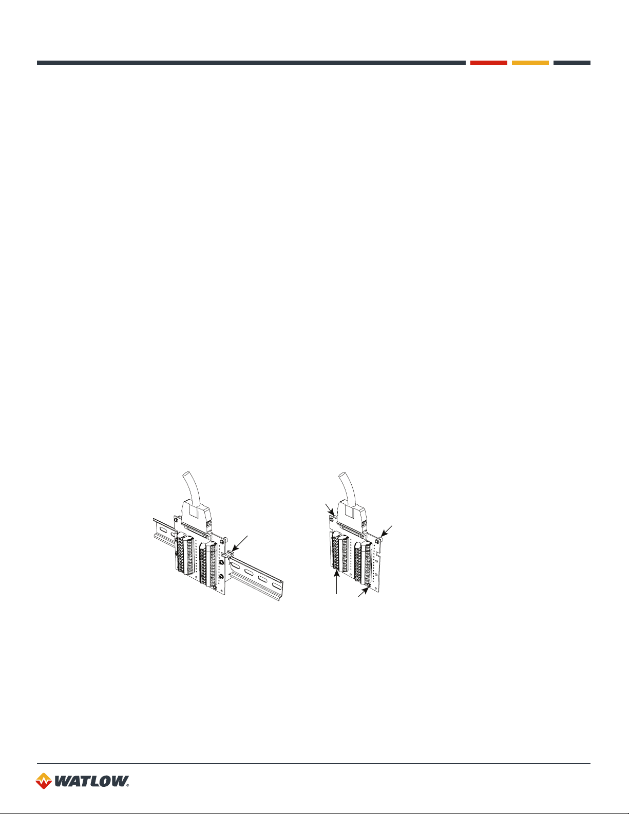
Mounting the TB50
There are two ways you can mount the TB50: use the pre-installed DIN rail mounting brackets or
use the plastic standoffs. Follow the corresponding procedure to mount the board.
DIN Rail Mount
Standoffs
Figure 2.6 — Mounting the TB50
23
Page 24
CLS200 Series User’s Guide
Chapter 2: Installation
DIN Rail Mounting
Snap the TB50 on to the DIN rail by placing the hook side on the rail first, then pushing the snap
latch side in place. (See Figure 2.7.)
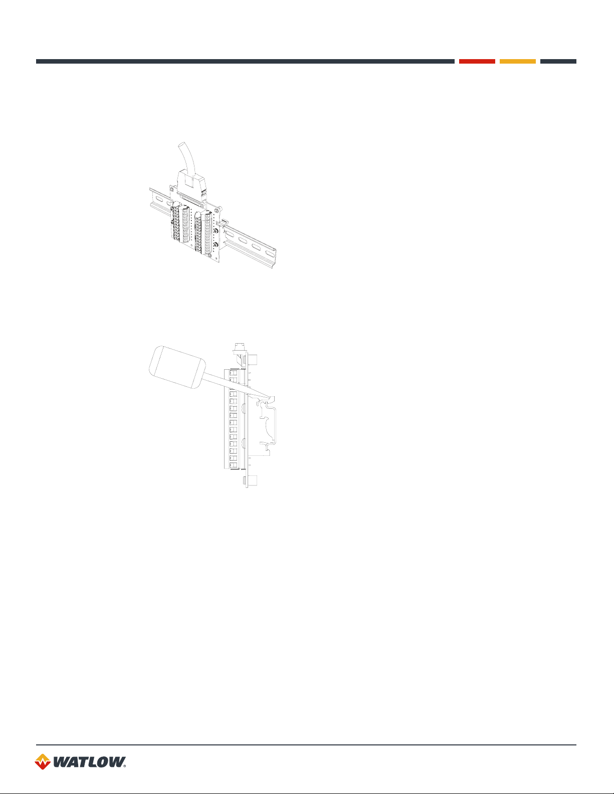
Figure 2.7 — TB50 Mounted on a DIN Rail (Front)
To remove the TB50 from the rail, use a flathead screwdriver to unsnap the bracket from the rail.
(See Figure 2.8.)
Figure 2.8 — TB50 Mounted on DIN Rail (Side)
Mounting with Standoffs
1. Remove the DIN rail mounting brackets from the TB50.
2. Select a location with enough clearance to remove the TB50, its SCSI cable and the controller
itself.
3. Mark the four mounting holes.
4. Drill and tap four mounting holes for #6 (3.5 mm) screws or bolts.
5. Mount the TB50 with four screws.
There are four smaller holes on the terminal board. Use these holes to secure wiring to the terminal
block with tie wraps.
24
Page 25
CLS200 Series User’s Guide
Chapter 2: Installation
0.2 in.
(5 mm)
3.6 in.
(91 mm)
3.6 in.
(91 mm)
0.7 in.
(18 mm)
Figure 2.9 — Mounting a TB50 with Standoffs
2.6 in.
(66 mm)
0.2 in.
(5 mm)
Mounting the Power Supply
Refer to the power supply manufacturer’s instructions for mounting information. Choose a Class 2
power supply that supplies an isolated regulated 12 to 24VDC at 1A.
Mounting Environment
Leave enough clearance around the power supply so that it can be removed.
System Wiring
Successful installation and operation of the control system can depend on placement of the
components and on selection of the proper cables, sensors, and peripheral components.
Routing and shielding of sensor wires and proper grounding of components can insure a robust
control system. This section includes wiring recommendations, instructions for proper grounding and
noise suppression, and considerations for avoiding ground loops.
WARNING! To reduce the risk of electrical shock, fire, and equipment damage, follow
all local and national electrical codes. Correct wire sizes, fuses and thermal breakers are
essential for safe operation of this equipment.
CAUTION! Do not wire bundles of low-voltage signal and control circuits next to
bundles of high voltage ac wiring. High voltage may be inductively coupled onto the
low-voltage circuits, which may damage the controller or induce noise and cause poor
control.
Physically separate high-voltage circuits from low-voltage circuits and from CLS200
hardware. If possible, install high-voltage ac power circuits in a separate panel.
25
Page 26

CLS200 Series User’s Guide
Chapter 2: Installation
Wiring Recommendations
Follow these guidelines for selecting wires and cables:
• Use stranded wire. (Solid wire can be used for fixed service; it makes intermittent connections
when you move it for maintenance.)
• Use 20 AWG (0.5 mm2) thermocouple extension wire. Larger or smaller sizes may be difficult
to install, may break easily, or may cause intermittent connections.
• Use shielded wire. The electrical shield protects the signals and the CLS200 from electrical
noise. Connect one end of the input and output wiring shield to earth ground.
• Use copper wire for all connections other than thermocouple sensor inputs.
Table 2.1 — Cable Recommendations
FUNCTION MFR. P/N NO. OF WIRES AWG MM
Analog Inputs
RTD Inputs
Thermocouple
Inputs
Control Outputs
and Digital I/O
Analog Outputs
Computer
Communication:
EIA/TIA-232, 422
or 485, or 20mA
Belden 9154
Belden 8451
Belden 8772
Belden 9770
T/C Ext. Wire 2 20 0.5
Belden 9539
Belden 9542
Ribbon Cable
Belden 9154
Belden 8451
Belden 9729
Belden 9730
Belden 9842
Belden 9843
Belden 9184
20
50
2
2
3
3
9
2
2
4
6
4
6
4
20
22
20
22
24
24
22 to 14
20
22
24
24
24
24
22
2
0.5
0.5
0.5
0.5
0.2
0.2
0.5 to 2.5
0.5
0.5
0.2
0.2
0.2
0.2
0.5
MAXIMUM LENGTH
4,000 ft. (1,219 m)
4,000 ft. (1,219 m)
6,000 ft. (1,829 m)
Noise Suppression
The CLS200’s outputs are typically used to drive solid state relays. These relays may in turn operate
more inductive types of loads such as electromechanical relays, alarm horns and motor starters.
Such devices may generate electromagnetic interference (EMI or noise). If the controller is placed
close to sources of EMI, it may not function correctly. Below are some tips on how to recognize and
avoid problems with EMI.
For earth ground wire, use a large gauge and keep the length as short as possible. Additional
shielding may be achieved by connecting a chassis ground strap from the panel to CLS200 case.
26
Page 27

CLS200 Series User’s Guide
Chapter 2: Installation
Symptoms of RFI/EMI
If your controller displays the following symptoms, suspect EMI:
• The controller’s display blanks out and then reenergizes as if power had been turned off for
a moment.
• The process variable does not display correctly.
Noise may also damage the digital output circuit—so digital outputs will not turn on. If the digital
output circuit is damaged, return the controller to Watlow for repair.
Avoiding RFI/EMI
To avoid or eliminate most RFI/EMI noise problems:
• Connect the CLS200 case to earth ground. The CLS200 system includes noise suppression
circuitry. This circuitry requires proper grounding.
• Separate the 120 or 240VAC power leads from the low-level input and output leads
connected to the CLS200 series controller. Do not run the digital I/O or control output leads in
bundles with ac wires.
• Where possible, use solid-state relays (SSRs) instead of electromechanical relays. If you must
use electromechanical relays, try to avoid mounting them in the same panel as the CLS200
series equipment.
• If you must use electromechanical relays and you must place them in a panel with CLS200
series equipment, use a 0.01 microfarad capacitor rated at 1000VAC (or higher) in series with
a 47Ω, 0.5 watt resistor across the normally-open contacts of the relay load. This is known as
a snubber network and can reduce the amount of electrical noise.
• You can use other voltage suppression devices, but they are not usually required. For
instance, you can place a metal oxide varistor (MOV) rated at 130VAC for 120VAC control
circuits across the load, which limits the peak ac voltage to about 180VAC. You can also
place a transorb (back-to-back zener diodes) across the digital output, which limits the digital
output voltage.
Additional Recommendations for a Noise Immune System
It is strongly recommended that you:
• Isolate outputs through solid-state relays, where possible.
• Isolate RTDs or “bridge” type inputs from ground.
• Isolate digital inputs from ground through solid state relays. If this is not possible, then make
sure the digital input is the only connection to earth ground other than the chassis ground.
• If you are using EIA/TIA-232 from a non-isolated host, either (1) do not connect any
other power common point to earth ground, or (2) use an optical isolator in the
communications line.
27
Page 28

CLS200 Series User’s Guide
Chapter 2: Installation
Ground Loops
Ground loops occur when current passes from the process through the controller to ground. This
can cause instrument errors or malfunctions.
A ground loop may follow one of these paths, among others:
• From one sensor to another.
• From a sensor to the communications port.
• From a sensor to the dc power supply.
The best way to avoid ground loops is to minimize unnecessary connections to ground. Do not
connect any of the following terminals to each other or to earth ground:
• Power supply dc common
• TB1, terminals 5, 6, 11, 12 (analog common)
• TB1, terminal 17 (reference voltage common)
• TB1, terminals 23, 24 (communications common)
• TB2, terminal 2 (dc power common)
Special Precautions for the Sixteen-Loop Models
Sixteen-loop models have single-ended inputs. All the negative sensor leads are tied to the analog
common. That means there is no sensor-to-sensor isolation. Proper grounding is critical for this unit.
Take these additional precautions with a sixteen-loop controller:
• Use all ungrounded or all well-grounded thermocouples, not a mix.
• If using a mixture of thermocouples or low-voltage inputs (<500mV) and current inputs,
connect the negative leads of the current transmitters to terminal 17 (Ref Com) on TB1.
• If using voltage transmitters, use only sourcing models or configuration. Sinking configurations
will not work.
• Isolate the controller’s communication port (if used) by using an optically isolated 232-to-485
converter.
Personal Computers and Ground Loops
Many PC communications ports connect the communications common to chassis ground. When
such a PC is connected to the controller, this can provide a path to ground for current from the
process that can enter the controller through a sensor (such as a thermocouple). This creates a
ground loop that can affect communications and other controller functions. To eliminate a ground
loop, either use an optically isolated communications adapter or take measures to ensure that
sensors and all other connections to the controller are isolated and not conducting current into
the unit.
28
Page 29
CLS200 Series User’s Guide
Chapter 2: Installation
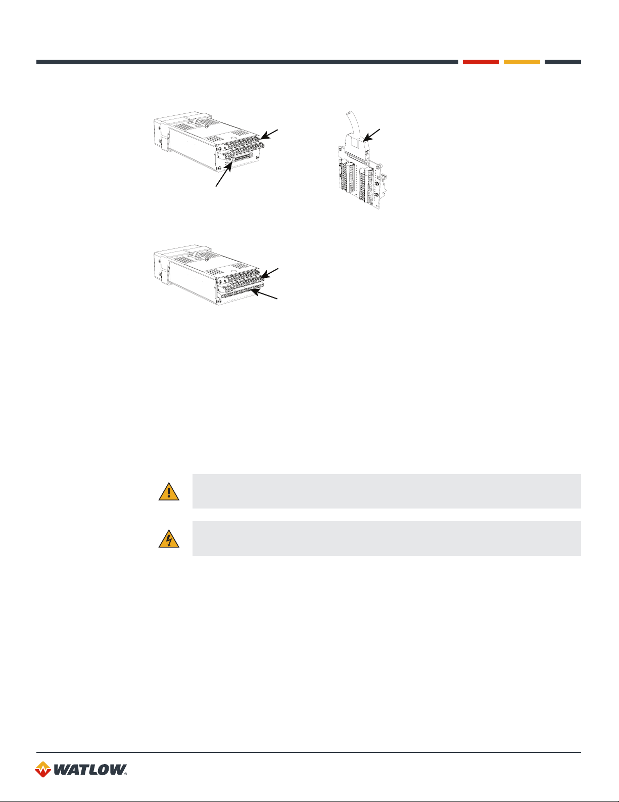
Power Connections
This section covers making the power connections to the CLS200 and connecting the TB50.
TB1
Sensor Inputs
TB2
Power Input
Figure 2.10 — CLS200 Series Controller with TB18
TB2
Power Input
Serial Communication
TB18
Digital Inputs
Digital Outputs
Pulse Input
TB1
Sensor Inputs
Serial Communication
SCSI to TB50
Digital Inputs
Digital Outputs
Pulse Input
Figure 2.11 — CLS200 Series Controller with TB50
Wiring the Power Supply
WARNING! Use a power supply with a Class 2 rating only. UL® approval requires a
Class 2 power supply.
Connect power to the controller before any other connections, This allows you to ensure that the
controller is working before any time is taken installing inputs and outputs.
Table 2.2 — Power Connections
FUNCTION POWER SUPPLY CLS200 TB2
DC Power (Controller) +12 to 24VDC +
DC Common 12 to 24VDC Common –
Earth Ground Ground
1. Connect the dc common terminal on the power supply to the dc common (-) terminal on
CLS200 TB2.
2. Connect the positive terminal on the power supply to the dc positive (+) terminal on
CLS200 TB2.
3. If using an isolated dc output or another power supply to power the loads, connect the dc
common of the supply powering the loads to the dc common of the supply powering the
controller.
29
Page 30
CLS200 Series User’s Guide
Chapter 2: Installation
4. Use the ground connector on TB2 for chassis ground. This terminal is connected to the
CLS200 chassis and must be connected to earth ground.
5. Connect 120/240VAC power to the power supply.
NOTE! Connect the dc common of the power supply used for loads to the dc common
of the supply powering the controller. If the supplies are not referenced to one another,
the controller’s outputs will not be able to switch the loads.
NOTE! When making screw terminal connections, tighten to 4.5 to 5.4 inch-pound
(0.5 to 0.6 Nm).
CAUTION! Without proper grounding, the CLS200 may not operate properly or may be
damaged.
CAUTION! To prevent damage from incorrect connections, do not turn on the ac power
before testing the connections as explained in Testing Your System on page 31.
NOTE! Do not connect the controller’s dc common (COM) to earth ground. Doing so will
defeat the noise protection circuitry, making measurements less stable.
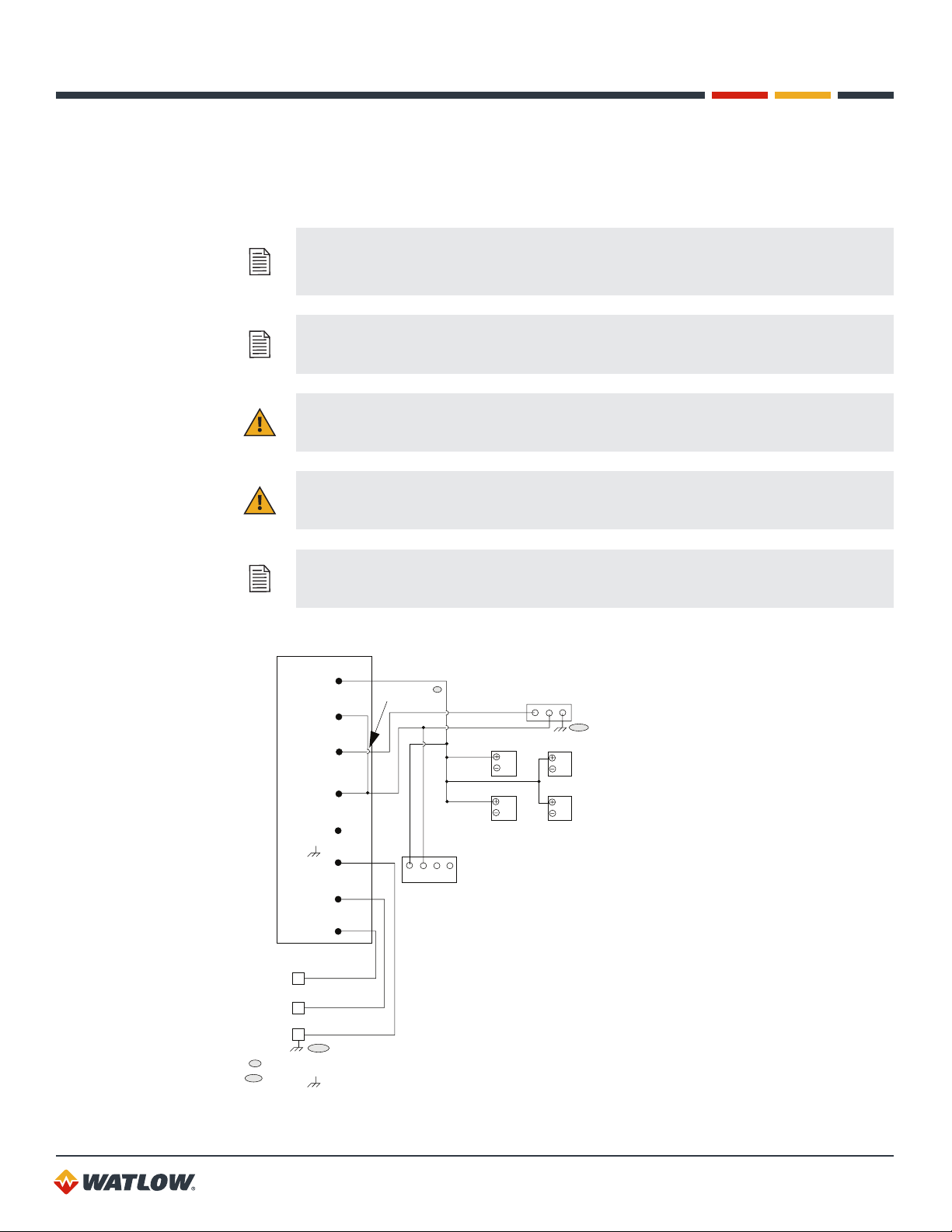
Power Supply
+V1 (5V)
0 (5V COM)
+V2 (+15V)
COM (15V COM)
-V2 (-15V)
(Ground)
ACL (AC Line)
ACN (AC Neutral)
white
120/240
VAC
Supply
N
black
H
green
G
* If using 5VDC for outputs, jumper 5V common to 15V common.
** Connect terminals to ac panel ground.
**
Add jumper *
1 2 3 4
+
C
5
O
M
SSR
SSR
Serial DAC
G
C
N
OMV
D
+
CLS200
**
SSR
SSR
Figure 2.12 — Power Connections
30
Page 31

CLS200 Series User’s Guide
Chapter 2: Installation
Connecting TB50 to CLS200
1. Connect the SCSI cable to the controller.
2. Connect the SCSI cable to the TB50.
Testing Your System
This section explains how to test the controller after installation and prior to making field wiring
connections.
TB50 or TB18 Test
Use this procedure to verify that the TB50 or TB18 is properly connected and supplied with power:
1. Turn on power to the CLS200. The display should read CALCULATING CHECKSUM then show
the bar graph display. (See Figure 3.3.) If you do not see these displays, disconnect power and
check wiring and power supply output.
2. Measure the +5VDC supply at the TB50 or TB18:
a. Connect the voltmeter’s common lead to TB50 or TB18 terminal 3 or TB18 terminal 2.
b. Connect the voltmeter’s positive lead to TB50 or TB18 screw terminal 1. The voltage
should be +4.75 to +5.25VDC.
Digital Output Test
Use this procedure to test the controller’s outputs before loads are connected. If using it at another
time for troubleshooting, disconnect loads from outputs before testing.
1. Connect a 500Ω to 100kΩ resistor between TB50 or TB18 screw terminal 1 and a digital
output terminal. (See Table 2.7 TB18 Connections; Table 2.8 TB50 Connections for CLS204
and CLS208; or Table 2.9 TB50 Connections for CLS216.)
2. Connect the voltmeter’s positive lead to screw terminal 1.
3. Connect the common lead to the digital output terminal.
4. Use the digital output test in the MANUAL I/O TEST menu to turn the digital output on and
off. (See Test Digital Output on page 94 and Digital Output Number on page 94.) When
the output is ON, the output voltage should be less than 1V. When the output is OFF, the
output voltage should be between 4.75 and 5.25V.
NOTE! By default, heat outputs are enabled. Only disabled outputs may be turned on
using the manual I/O test. To test heat outputs, set the corresponding loop to manual
mode 100% output. See Selecting the Control Status on page 56.
Digital Input Test
Use the following procedure to test digital inputs before connecting to field devices:
1. Disconnect any system wiring from the input to be tested.
2. Go to the DIGITAL INPUTS test in the MANUAL I/O TEST menu. (See Digital Inputs on
page 94.) This test shows whether the digital inputs are H (high, or open) or L (low, or
closed).
31
Page 32

CLS200 Series User’s Guide
Chapter 2: Installation
3. Attach a wire to the terminal of the digital input you want to test. See Table 2.7 to Table 2.9 for
connections.
a. When the wire is connected only to the digital input terminal, the digital input test should
show that the input is H (high, or open).
b. When you connect the other end of the wire to the controller common (TB50 terminal 3 or
TB18 terminal 2), the digital input test should show that the input is L (low, or closed).
Sensor Wiring
This section describes how to properly connect thermocouples, RTDs, current and voltage inputs to
your controller. The controller can accept any mix of available input types. Some input types require
that special scaling resistors be installed (done by Watlow before the controller is delivered).
All inputs are connected to the terminals on TB1 on the back of the controller. The tables below list
the connector locations.
CAUTION! Never run input leads in bundles with high power wires or near other sources
of EMI. This could inductively couple voltage onto the input leads and damage the
controller, or could induce noise and cause poor measurement and control.
Table 2.3 — Analog Input Connections on TB1 for Four-Loop and Eight-Loop Models
INPUT + TERMINAL – TERMINAL
Input 1 1 2
Input 2 3 4
Input 3 7 8
Input 4 9 10
Input 5 13 14
Input 6 15 16
Input 7 19 20
Input 8 21 22
Table 2.4 — Analog Input Connections on TB1 for Sixteen-Loop Models
INPUT + TERMINAL COMMON REFERENCE COMMON*
Input 1 1 5 17
Input 2 3 5 17
Input 3 7 5 17
Input 4 9 5 17
Input 5 13 11 17
Input 6 15 11 17
Input 7 19 11 17
Input 8 21 11 17
32
Page 33

CLS200 Series User’s Guide
Chapter 2: Installation
INPUT + TERMINAL COMMON REFERENCE COMMON*
Input 9 2 6 17
Input 10 4 6 17
Input 11 8 6 17
Input 12 10 6 17
Input 13 14 12 17
Input 14 16 12 17
Input 15 20 12 17
Input 16 22 12 17
*
For sixteen-loop controllers when mixing current inputs and low-voltage inputs (thermocouples or voltage inputs less than
1V), connect the current signal to the positive input and reference common (terminal TB1-17). If no low-voltage sensors are
used, connect current inputs to the positive input and common terminals listed in the table above.
Input Wiring Recommendations
Use multicolored stranded shielded cable for analog inputs. Watlow recommends that you use
20 AWG wire (0.5 mm2). If the sensor manufacturer requires it, you can also use 24 or 22 AWG
wiring (0.2 mm2). Most inputs use a shielded twisted pair; some require a 3-wire input.
Follow the instructions pertaining to the type(s) of input(s) you are installing.
The controller accepts the following inputs without any special scaling resistors:
• J, K, T, S, R, B and E thermocouples.
• Linear inputs with ranges between -10 and 60mV.
Any unused inputs should be set to SKIP or jumpered to avoid thermocouple break alarms.
Thermocouple Connections
Connect the positive lead of any of the supported thermocouple types to the IN+ terminal for one of
the loops and the negative lead to the corresponding IN- terminal.
Use 18 or 20 AWG (0.5 or 0.75 mm2) for all the thermocouple inputs. Most thermocouple wire is
solid, unshielded wire. When using shielded wire, ground one end only.
CH IN+
*CH IN-
White
Red
Shield (if present)
Type J
thermocouple
Earth Ground
at Process End
*For sixteen-channel models connect negative to Com on TB1
Figure 2.13 — Thermocouple Connections
33
Page 34

CLS200 Series User’s Guide
Com
Chapter 2: Installation
NOTE! When mixing current inputs with low-voltage inputs (thermocouples or voltage
inputs less than 1V) to a sixteen-loop controller, connect the current inputs to the IN+
and Ref Com terminals. If no low-voltage sensors are used, connect current inputs to the
IN+ and Com terminals on TB1. For all inputs to a four or eight-loop controller, connect
the sensors to the IN+ and IN- terminals.
CAUTION! Ground loops and common mode noise can damage the controller or disrupt
measurements. To minimize ground loops and common mode noise:
• With a sixteen-loop controller, use only ungrounded thermocouples with each
thermocouple sheath electrically connected to earth ground. The negative sensor
terminals on sixteen-loop controllers are tied to analog common.
• With a four-loop or eight-loop controller, do not mix grounded and ungrounded
thermocouples. If any thermocouple connected to the controller is of grounded
construction, all thermocouples should be of grounded construction and each should be
connected to ground at the process end.
• Connect the earth ground terminal on TB2 to a good earth ground, but do not connect the
analog common to earth ground. The CLS200 uses a floating analog common for sensor
measurements. The noise protection circuits on the sensor inputs function correctly only
when the controller is correctly installed. See Ground Loops on page 28.
RTD Input Connections
This input type requires scaling resistors. Watlow recommends that you use a 100 W, 3-wire
platinum RTD to prevent reading errors due to cable resistance. If you use a 2-wire RTD, jumper the
negative input to common. If you must use a 4-wire RTD, leave the fourth wire unconnected.
CH IN +
100Ω RTD
CH IN –
Figure 2.14 — RTD Connections
Reference Voltage Terminals
The +5V Ref and Ref Com terminals are provided in order to power external bridge circuits for
special sensors. Do not connect any other types of devices to these terminals.
Voltage Input Connections
This input type requires scaling resistors. Special input resistors installed at Watlow divide analog
input voltages such that the controller sees a -10 to 60mV signal on the loop.
34
Page 35

CLS200 Series User’s Guide
Four-Loop or Eight-Loop Controller
Chapter 2: Installation
CH IN+
CH IN-
Sixteen-Loop Controller
CH IN+
Com
Figure 2.15 — Linear Voltage Signal Connections
Device with
Voltage
Output
Device with
Voltage
Output
Current Input Connections
This input type requires scaling resistors. Special input resistors installed at Watlow for analog
current signals are such that the controller sees a -10 to 60mV signal across its inputs for the loop.
Four-Loop or Eight-Loop Controller
CH IN+
CH IN-
Sixteen-Loop Controller
Device with
Current
Output
CH IN+
Com/Ref Com
Figure 2.16 — Linear Current Signal Connections
NOTE! When mixing current inputs with low-voltage inputs (thermocouples or voltage
inputs less than 1V) to a sixteen-loop controller, connect the current inputs to the IN+
and Ref Com terminals. If no low-voltage sensors are used, connect current inputs to the
IN+ and Com terminals on TB1.
Device with
Current
Output
Pulse Input Connections
The CLS200 can accept a pulse input of up to 2000Hz from a device such as an encoder. The
frequency of this input is scaled with user-set parameters. See Setup Loop Input Menu on page
74 and Example 3: A Pulse Encoder on page 161. This scaled value is the process variable for
loop 5 on a four-loop model, loop 9 on an eight-loop model or loop 17 on a sixteen-loop model.
The CLS200 can accommodate encoder signals up to 24VDC using a voltage divider or can
power encoders with the 5VDC from the TB50 or TB18. The following figures illustrate connecting
encoders. A pull-up resistor in the CLS200 allows open collector inputs to be used.
35
Page 36

CLS200 Series User’s Guide
Chapter 2: Installation
CLS200 and TB50 or TB18
+5VDC
10kΩ
Pulse Input
Encoder
Com
Figure 2.17 — Encoder with 5VDC TTL Signa
+5VDC
10kΩ
Figure 2.18 — Encoder Input with Voltage Divider
Pulse Input
Com
R2
R1
Encoder
For encoders with signals greater than 5VDC, use a voltage divider to drop the voltage to 5 volts at
the input. Use appropriate values for R1 and R2 depending on the encoder excitation voltage. Be
sure not to exceed the specific current load on the encoder.
Wiring Control and Digital I/O
This section describes how to wire and configure the control outputs for the CLS200 series
controller.
NOTE! Control outputs are connected to the CLS200’s common when the control output
is on (low). Be careful when you connect external devices that may have a low side at a
voltage other than controller ground, since you may create ground loops.
If you expect grounding problems, use isolated solid state relays and isolate the control
device inputs.
The CLS200 provides dual PID control outputs for each loop. These outputs can be enabled or
disabled, and are connected via TB50 or TB18.
Output Wiring Recommendations
When wiring output devices, use multicolored, stranded, shielded cable for analog outputs and digital
outputs connected to panel-mounted solid state relays.
• Analog outputs usually use a twisted pair.
• Digital outputs usually have 9 to 20 conductors, depending on wiring technique.
36
Page 37

CLS200 Series User’s Guide
Chapter 2: Installation
Cable Tie Wraps
Once you have wired outputs to the TB50, install the cable tie wraps to reduce strain on the
connectors.
Each row of terminals has a cable tie wrap hole at one end. Thread the cable tie wrap through the
cable tie wrap hole. Then wrap the cable tie wrap around the wires attached to that terminal block.
Digital Outputs
The CLS200 series provides dual control outputs for up to 16 loops. The controller’s default
configuration has all heat outputs enabled and all cool outputs disabled. Disabling a heat output
makes that output available to be used as a control or an alarm output. See Enable or Disable Heat
or Cool Outputs on page 85. The CPU watchdog timer output can be used to monitor the state of
the controller with an external circuit or device. See CPU Watchdog Timer on page 39.
Table 2.5 — Digital Output States and Values Stored in the Controller
STATE VALUE DESCRIPTION
Off High Open circuit
On Low Sinking current to common
The digital outputs sink current from the load to the controller common. The load may powered by
the 5VDC supplied by the controller at the TB50. Alternately, an external power supply may be used
to drive loads.
Keep in mind the following points when using an external power supply:
• The CLS200 power supply available from Watlow includes a 5VDC supply. When using
it to supply output loads, connect the 5VDC common to the 15VDC common at the
power supply.
• Do not exceed +24 volts.
• If you tie the external load to earth ground, or if you cannot connect it as shown in
(See Figure 2.21), then use a solid-state relay.
All digital outputs are sink outputs referenced to the CLS200 series controller common supply. These
outputs are low (pulled to common) when they are on.
The outputs conduct current when they are low or on. The maximum current sink capability is 60mA
at 24VDC. They cannot “source” current to a load.
37
Page 38

CLS200 Series User’s Guide
Chapter 2: Installation
TB50 or TB18
+5VDC
Loads
External
Power
Supply
+
-
Digital Output 1
Digital Output 2
Do not connect
to earth ground or
equipment ground
TB50 or TB18
Using Internal Power Supply
Control Common
Loads
Digital Output 1
Digital Output 2
Using External Power Supply
Figure 2.19 — Digital Output Wiring
Configuring Outputs
Keep in mind the following points as you choose outputs for control and alarms:
• You can enable or disable the control outputs. The default setting is heat outputs enabled,
cool outputs disabled.
• You can program each control output individually for on/off, time proportioning, distributed
zero crossing, or Serial DAC control.
• You can individually program each control output for direct or reverse action.
• Alarm outputs other than the global alarm are nonlatching.
• Alarms can be suppressed during process start up and for preprogrammed durations. See
Alarm Delay on page 93.
• Alarm outputs can be configured as a group as normally on (low) or normally off (high). See
Digital Output Polarity on Alarm on page 73.
Control and Alarm Output Connections
Typically control and alarm outputs use external optically isolated solid state relays (SSRs). SSRs
accept a 3 to 32VDC input for control, and some can switch up to 100 Amps at 480VAC. For larger
currents, use silicon control rectifier (SCR) power controllers up to 1000 Amps at 120 to 600VAC.
You can also use SCRs and a Serial DAC for phase-angle fired control.
The 34 control and alarm outputs are open collector outputs referenced to the CLS200’s common.
Each output sinks up to 60mA DC to the controller common when on.
38
Page 39

CLS200 Series User’s Guide
Chapter 2: Installation
NOTE! Control outputs are SINK outputs. They are Low when the output is ON. Connect
them to the negative side of solid state relays.
Figure 2.20 shows sample heat, cool and alarm output connections.
TB50 or TB18
Heat Output
Cool Output
Alarm Output
+5VDC
Figure 2.20 — S ample Heat, Cool and Alarm Output Connections
TB50 or TB18
Heat Output
Cool Output
Alarm Output
Common
Figure 2.21 — Output Connections Using External Power Supply
SSR SSR SSR
+-
SSR
+-
- PS +
+-
SSR
+-
+-
SSR
+-
CPU Watchdog Timer
The CPU watchdog timer constantly monitors the microprocessor. It is a sink output located on
TB50 terminal 6 or TB18 terminal 3. The output can be connected to an external circuit or device
in order to determine if the controller is powered and operational. Do not exceed 5VDC, 10mA DC)
rating for the watchdog output. The output is low (on) when the microprocessor is operating; when it
stops operating, the output goes high (off).
Figure 2.22 and Figure 2.23 show the recommended circuit for the watchdog timer output for the
TB50 and the TB18.
TB50
+ 5VDC
(Terminal 1)
Watchdog Timer
(Terminal 6)
Figure 2.22 — TB50 Watchdog Timer Output
+
SSR
-
39
Page 40

CLS200 Series User’s Guide
Chapter 2: Installation
TB18
+ 5VDC
(Terminal 1)
Watchdog Timer
+
SSR
-
(Terminal 3)
Figure 2.23 — TB18 Watchdog Timer Output
Digital Inputs
All digital inputs are transistor-transistor logic (TTL) level inputs referenced to control common and
the internal +5V power supply of the CLS200.
When an input is connected to the controller common, the input is considered on. Otherwise, the
input is considered off. Most features that use the digital inputs can be user-configured to activate
when an input is either on or off.
In the off state, internal 10k resistors pull the digital inputs high to 5VDC with respect to the controller
common.
Table 2.6 — Digital Inputs States and Values Stored in the Controller
STATE VALUE DESCRIPTION
Off High Open circuit
On Low DIgital input connected to controller common
External Switching Devices
To ensure that the inputs are reliably switched, use a switching device with the appropriate
impedances in the on and off states and do not connect the inputs to external power sources.
When off, the swiching device must provide an impedance of at least 11kΩ to ensure that the
voltage will rise to greater than 3.7VDC. When on, the switch must provide not more than 1kΩ
impedance to ensure the voltage drops below 1.3VDC.
To install a switch as a digital input, connect one lead to the common terminal on the TB50
(terminals 3 and 4) or TB18 (terminal 2). Connect the other lead to the desired digital input terminal
on the TB50 (terminals 43 to 50) or TB18 (terminals 16 to 18).
Functions Activated by Digital Inputs
Use digital inputs to activate the following functions:
• Load a job that is stored in controller memory. See Job Select Digital Inputs on page 68.
• Change all loops to manual mode at specified output levels. See Output Override Digital Input
on page 70.
• Enable thermocouple short detection. See Process Power Digital Input on page 71.
• Restore control automatically after a failed sensor has been repaired. See Restore PID Digital
Input on page 83.
40
Page 41

CLS200 Series User’s Guide
Chapter 2: Installation
TB50
Input
Control Com
Figure 2.24 — Wiring Digital Inputs
TB18 Connections
Table 2.7 — TB18 Connections
TERMINAL FUNCTION
1 +5VDC
2 CTRL COM
3 Watchdog timer
4 Global alarm
5 Output 1 Loop 1 heat Loop 1 heat
6 Output 2 Loop 2 heat Loop 2 heat
External
Switching
Device
FOUR-LOOP
CONTROLLER
CONTROL OUTPUT
CONTROLLER
1
EIGHT-LOOP
7 Output 3 Loop 3 heat Loop 3 heat
8 Output 4 Loop 4 heat Loop 4 heat
9 Output 5 Pulse loop heat Loop 5 heat
10 Output 6 Loop 1 cool Loop 6 heat
11 Output 7 Loop 2 cool Loop 7 heat
12 Output 8 Loop 3 cool Loop 8 heat
13 Output 9 Loop 4 cool Pulse loop heat
14 Output 10 Pulse loop cool Loop 1 cool
15 Output 34
2
Serial DAC clock Serial DAC clock
16 Input 1
17 Input 2
18 Input 3/Pulse input
1
The indicated outputs are dedicated for control when enabled in the loop setup. If one or both of a loop’s outputs are
disabled, the corresponding digital outputs become available for alarms or ramp/soak events.
2
For Watlow Serial DAC, the CLS200 series controller uses digital output 34 for a clock line. You cannot use output 34 for
anything else when you have a control output configured for the SDAC.
41
Page 42

CLS200 Series User’s Guide
Chapter 2: Installation
TB50 Connections
Table 2.8 — TB50 Connections for Four-Loop and Eight-Loop Controllers
TERMINAL FUNCTION
CONTROL OUTPUT
8-LOOP 4-LOOP 8-LOOP 4-LOOP
1 +5VDC 2 +5VDC
3
CTRL
COM
5 Not Used 6
7
Pulse
Input
9 Output 1 Loop 1 heat Loop 1 heat 10 Output 34
11 Output 2 Loop 2 heat Loop 2 heat 12 Output 33
13 Output 3 Loop 3 heat Loop 3 heat 14 Output 32
15 Output 4 Loop 4 heat Loop 4 heat 16 Output 31
17 Output 5 Loop 5 heat
19 Output 6 Loop 6 heat Loop 1 cool 20 Output 29
21 Output 7 Loop 7 heat Loop 2 cool 22 Output 28
23 Output 8 Loop 8 heat Loop 3 cool 24 Output 27
25 Output 9
Pulse loop
heat
27 Output 10 Loop 1 cool
29 Output 11 Loop 2 cool 30 Output 24
31 Output 12 Loop 3 cool 32 Output 23
33 Output 13 Loop 4 cool 34 Output 22
35 Output 14 Loop 5 cool 36 Output 21
37 Output 15 Loop 6 cool 38 Output 20
39 Output 16 Loop 7 cool 40 Output 19
41 Output 17 Loop 8 cool 42 Output 18
43 Input 1 44 Input 2
45 Input 3 46 Input 4
47 Input 5 48 Input 6
49 Input 7 50 Input 8
1
The indicated outputs are dedicated for control when enabled in the loop setup. If one or both of a loop’s outputs are
disabled, the corresponding digital outputs become available for alarms or ramp/soak events.
2
For Watlow Serial DAC, the controller uses digital output 34 (terminal 10) for a clock line. You cannot use output 34 for
anything else when you have a control output configured for the SDAC.
1
TERMINAL FUNCTION
4 CTRL COM
Watchdog
Timer
Global
Alarm
Pulse loop
heat
8
18 Output 30
Loop 4 cool 26 Output 26
Pulse loop
cool
28 Output 25
CONTROL OUTPUT
2
Pulse
loop cool
1
42
Page 43

CLS200 Series User’s Guide
Chapter 2: Installation
Table 2.9 — TB50 Connections for Sixteen-Loop Controllers
TERMINAL FUNCTION
CONTROL
OUTPUT
1
TERMINAL FUNCTION
CONTROL
OUTPUT
1 +5VDC 2 +5VDC
3 CTRL COM 4 CTRL COM
5 Not Used 6
Watchdog
Timer
7 Pulse Input 8 Global Alarm
9 Output 1 Loop 1 heat 10 Output 34
2
Pulse loop cool
11 Output 2 Loop 2 heat 12 Output 33 Loop 16 cool
13 Output 3 Loop 3 heat 14 Output 32 Loop 15 cool
15 Output 4 Loop 4 heat 16 Output 31 Loop 14 cool
17 Output 5 Loop 5 heat 18 Output 30 Loop 13 cool
19 Output 6 Loop 6 heat 20 Output 29 Loop 12 cool
21 Output 7 Loop 7 heat 22 Output 28 Loop 11 cool
23 Output 8 Loop 8 heat 24 Output 27 Loop 10 cool
25 Output 9 Loop 9 heat 26 Output 26 Loop 9 cool
27 Output 10 Loop 10 heat 28 Output 25 Loop 8 cool
29 Output 11 Loop 11 heat 30 Output 24 Loop 7 cool
1
31 Output 12 Loop 12 heat 32 Output 23 Loop 6 cool
33 Output 13 loop 13 heat 34 Output 22 Loop 5 cool
35 Output 14 Loop 14 heat 36 Output 21 Loop 4 cool
37 Output 15 Loop 15 heat 38 Output 20 Loop 3 cool
39 Output 16 Loop 16 heat 40 Output 19 Loop 2 cool
41 Output 17 Pulse loop heat 42 Output 18 Loop 1 cool
43 Input 1 44 Input 2
45 Input 3 46 Input 4
47 Input 5 48 Input 6
49 Input 7 50 Input 8
1
The indicated outputs are dedicated for control when enabled in the loop setup. If one or both of a loop’s outputs are
disabled, the corresponding digital outputs become available for alarms or ramp/soak events.
2
For Watlow Serial DAC, the controller uses digital output 34 (terminal 10) for a clock line. You cannot use output 34 for
anything else when you have a control output configured or the SDAC.
43
Page 44

CLS200 Series User’s Guide
Chapter 2: Installation
Analog Outputs
Analog outputs can be provided by using a Dual DAC or Serial DAC module to convert the open
collector outputs from the controller. Use multicolored stranded shielded cable for analog outputs.
Analog outputs generally use a twisted pair wiring. The following sections describe the Dual DAC
and Serial DAC modules.
Wiring the Dual DAC
A Dual DAC module includes two identical circuits. Each can convert a distributed zero-cross (DZC)
signal from the controller to a voltage or current signal. Watlow strongly recommends using a power
supply separate from the controller supply to power the Dual DAC. Using a separate power supply
isolates the controller’s digital logic circuits and analog measurement circuits from the frequently
noisy devices that take the analog signal from the Dual DAC.
Several Dual DAC modules may be powered by one power supply. Consult the Dual DAC’s manual
for power requirements. Also note that the Dual DAC does not carry the same industry approvals as
the Serial DAC.
Wiring the Serial DAC
The Serial DAC provides a robust analog output signal. The module converts the proprietary Serial
DAC signal from the controller’s open collector output in conjunction with the clock signal to an
analog current or voltage. The Serial DAC is user-configurable for voltage or current output.
The Serial DAC optically isolates the controller’s control output from the load. When a single
Serial DAC is used, it may be powered by the 5VDC found on the TB50, or by an external supply
referenced to the controller’s power supply. When using multiple Serial DACs, the controller cannot
provide sufficient current; use the 5VDC output from the CLS200 power supply.
Serial Communications
The CLS200 series controllers are factory-configured for EIA/TIA-232 communications unless
otherwise specified when purchased. However, the communications are jumper-selectable, so you
can switch between EIA/TIA-232 and EIA/TIA-485. See Changing Communications on page 153.
EIA/TIA-232 Interface
EIA/TIA-232 provides communication to the serial port of a compatible computer. It is used for single
controller installations where the cable length does not exceed 50 feet (15.2 m).
The EIA/TIA-232 interface is a standard three-wire interface. See the table below for connection
information.
If you are using EIA/TIA-232 communications with grounded thermocouples, use an optical isolator
between the controller and the computer to prevent ground loops.
Table 2.10 shows EIA/TIA-232 connections for 25-pin and 9-pin connectors.
EIA/TIA-232 may be used to connect a computer through a 232/485 converter, to an EIA/TIA-485
communications network with up to 32 CLS200 controllers.
44
Page 45

CLS200 Series User’s Guide
Chapter 2: Installation
Table 2.10 — EIA/TIA-232 Connections
WIRE COLOR CLS200 TB1 DB 9 CONNECTOR DB 25 CONNECTOR
White TX Pin 26 RX Pin 2 RX Pin 3
Red RX Pin 25 TX Pin 3 TX Pin 2
Black GND Pin 23 GND Pin 5 GND Pin 7
Green GND Pin 24 N/U Pin 9 N/U Pin 22
Shield N/C GND Pin 5 GND Pin 7
Jumpers in EIA/TIA-232 Connectors
Some software programs and some operator interface terminals require a Clear to Send (CTS) signal
in response to their Request to Send (RTS) signal, or a Data Set Ready (DSR) in response to their
Data Terminal Ready (DTR). The CLS200 is not configured to receive or transmit these signals. To
use such software with the CLS200, jumper the RTS to the CTS and the DTR to the DSR in the DB
connector. Table 2.11 lists the standard pin assignments for DB-9 and DB-25 connectors.
Table 2.11 — RTS/CTS Pins in DB-9 and DB-25 Connectors
DB-9 DB-25
RTS 7 4
CTS 8 5
DTR 4 20
DSR 6 6
Cables manufactured by Watlow for EIA/TIA-232 communications include these jumpers.
EIA/TIA-232
cable
RAMP
SOAK
M
R
A
L
A
K
C
A
UNITS
R
NTE
E
OUT%
PROCESS
BACK
LOOP
STATUS
WATLOW ANAFAZE CLS200
O
N
SETPOINT
YES
ALARM
CHNG
SP
MAN
AUTO
Figure 2.25 — Connecting One CLS200 to a Computer Using EIA/TIA-232
45
Page 46

CLS200 Series User’s Guide
Chapter 2: Installation
EIA/TIA-485 Interface
To communicate with more than one CLS200 series controller on a controller network, or to use
communication cable lengths greater than 50 feet (15.2 m) from PC to controller, you must use
EIA/TIA-485 communications.
When using EIA/TIA-485 communications, you must attach an optically isolated EIA/TIA-232 to
EIA/TIA-485 converter to the computer.
Figure 2.26 and Figure 2.27 show the recommended system wiring. To avoid ground loops, use an
optically isolated EIA/TIA-232 to EIA/TIA-485 converter between the computer and the EIA/TIA-485
network.
Personal Computer
Figure 2.26 — EIA/TIA-485 Wiring
EIA/TIA-485 Converter
TXA/TDA/TX-
TXB/TDB/TX+
RXA/RDA/RX-
RXB/RDB/RX+
First CLS200 Last CLS200
JU1
RXA 25
RXB 23
TXA 26
TXB 24
JU1
A
B
Do not
connect
shield to
CLS200
RXA 25
RXB 23
TXA 26
TXB 24
A
B
Cable Recommendations
Watlow recommends Belden 9843 cable or its equivalent. This cable includes three 24 AWG
(0.2 mm2) shielded, twisted pairs. It should carry signals of up to 19.2k baud with no more than
acceptable losses for up to 4,000 feet (1,220 m).
EIA/TIA-485 Network Connections
Watlow recommends that you use a single daisy chain configuration rather than spurs. Run a
twisted-pair cable from the host or the converter to the first CLS200, and from that point run a
second cable to the next CLS200, and so on. (See Figure 2.27.)
If necessary for servicing, instead of connecting each controller directly into the next, install a
terminal strip or connector as close as possible to each CLS200, run a communications cable from
one terminal strip to the next and connect the controllers to the bus with short lengths of cable.
To avoid unacceptable interference, use less than 10 feet (3 m) of cable from the terminal or
connector to the CLS200 serial port.
Some systems may experience problems with sensor signal reading if the commons of multiple
controllers are connected. See Signal Common on page 47.
Refer to Termination on page 47 for more on terminating resistors.
Connect the shield drain to earth ground only at computer or host end.
46
Page 47

CLS200 Series User’s Guide
First CLS200 Second CLS200 Last CLS200
Chapter 2: Installation
232 Communications 485 Communications
Serial Port
Optically
Shielded Twisted Pair Cable
Isolating
232 to 485
Converter
RAMP
SOAK
RM
LA
A
LOOP
WATLOW ANAFAZE CLS200
ALARM
CHNG
SP
MAN
AUTO
K
C
A
UNITS
R
E
T
N
E
OUT%
PROCESS
CK
BA
STATUS
NO
SETPOINT
S
E
Y
LOOP
WATLOW ANAFAZE CLS200
ALARM
H
C
S
N
A
M
O
T
U
A
P
M
A
K
R
A
O
S
M
R
A
L
A
CK
A
UNITS
ENTER
OUT%
PROCESS
K
AC
B
STATUS
O
N
SETPOINT
S
E
Y
G
N
P
PROCESS
LOOP
WATLOW ANAFAZE CLS200
SETPOINT
ALARM
G
N
H
C
P
S
N
A
M
O
T
U
A
P
M
A
K
R
A
O
S
M
R
A
L
A
K
C
A
UNITS
ENTER
OUT%
CK
BA
STATUS
O
N
S
E
Y
Figure 2.27 — Recommended System Connections
Signal Common
For usual installations, do not connect the dc commons of the controllers together or to the
converter or host device. Use an optically isolating EIA/TIA-232-to-485 converter to prevent
problems with sensor readings.
Termination
In order for EIA/TIA-485 signals to be transmitted properly, each pair must be properly terminated.
The value of the termination resistor should be equal to the impedance of the communications cable
used. Values are typically 150 to 200Ω.
The receive lines at the converter or host device should be terminated in the converter, the
connector to the host device or the device itself. Typically the converter documentation provides
instructions for termination.
Use a terminating resistor on the receive lines on the last controller on the 485 line. Set JU1 inside
the CLS200 in position B to connect a 200Ω resistor across the receive lines. Refer to Changing
Communications on page 153.
EIA/TIA-485 Converters and Laptop Computers
In order for an EIA/TIA-232-to-485 converter to optically isolate the computer from the 485 network,
the 232 and 485 sides must be powered independently. Many 232-to-485 converters can be
powered by the computer’s communications port. Some computers, laptops in particular, do not
automatically provide the appropriate voltages. These computer/ converter combinations can usually
be used by connecting an external power supply to the 232 side of the converter. Not all converters
have power inputs for the 232 side, however.
47
Page 48

Chapter 3: Using CLS200
This chapter explains how to use the keypad and display to operate the controller. Figure 3.1 shows
the operator menus and displays accessible from the front panel. To change global parameters, loop
inputs, control parameters, outputs, and alarms using the setup menus, see Chapter 4: Setup.
BACK
Power
on
Bar Graph
Display
BACK
Single Loop
Display
BACK
Job
Display
ENTER
ENTER
Scanning
Bar Graph
Display
Figure 3.1 — Operator Displays
Any
Key
ENTER
ENTER
Scanning
Single Loop
Display
Any
Key
RAMP
SOAK
Ramp/Soak
BACK
CHNG
SP
Change
Setpoint
BACK
MAN
AUTO
Manual,
Automatic
or Autotune
Mode
BACK
ENTER
(Manual)
BACK
Heat/Cool
Output
Percentage
(Manual
mode only)
48
Page 49

CLS200 Series User’s Guide
Chapter 3: Using CLS200
Front Panel
The CLS200 front panel provides a convenient interface with the controller. You can use the front
panel keys to program and operate the CLS200.
RAMP SOAK
• Assigns and
monitors profiles
ALARM ACK
MAN AUTO
• Changes loop output
control from automatic
to manual or tune
• Assigns output power
level of manual loops
CHNG SP
• Changes process
setpoint
YES
• Selects a menu
or parameter
• Answers YES to
YES/NO prompts
• Increases a
value or choice
BACK
• Cancels editing
and returns to a
previous menu
NO
• Skips a menu or parameter
• Answers NO to YES/NO
prompts
• Decreases a value or choice
• Acknowledges
alarms
ENTER
• Stores data or settings
and advances to the next
parameter
• Starts scanning mode
(if pressed twice)
Figure 3.2 — CLS200 Front Panel
Front Panel Keys
YES (up) Press YES to:
NO (down) Press NO to:
• Select a menu or parameter
• Answer YES to the flashing ? prompts
• Increase a value or choice when editing
• Stop scanning mode
• Skip a menu or parameter when the prompt is blinking
• Answer NO to the flashing ? prompts
• Decrease a value or choice when editing
• Stop scanning mode
• Perform a NO-key reset
49
Page 50

CLS200 Series User’s Guide
Chapter 3: Using CLS200
NOTE! Pressing the NO key on power up performs a NO-key reset. This procedure
clears the RAM and sets the controller’s parameters to their default values. See NO-Key
Reset on page 150.
BACK Press BACK to:
• Cancel editing
• Return to a previous menu
• Switch between bar graph, single loop and job displays
• Stop scanning mode
ENTER Press ENTER to:
• Store data or a parameter choice after editing and go to the
next parameter
• Start scanning mode (if pressed twice)
CHNG SP Press CHNG SP to change the loop setpoint
MAN AUTO Press MAN/AUTO to:
• Toggle a loop between manual and automatic control
• Adjust the output power level of manual loops
• Automatically tune the loop
RAMP SOAK If your controller has the ramp/soak option, press RAMP/SOAK to:
• Assign a ramp/soak profile to the current loop
• Select the ramp/soak mode
• See the status of a running profile
Your controller may not have the ramp/soak option. If it does not,
pressing the RAMP/SOAK key displays the message OPTION
UNAVAILABLE.
ALARM ACK Press ALARM ACK to:
• Acknowledge an alarm condition
• Reset the global alarm output
50
Page 51

CLS200 Series User’s Guide
Control Status
Chapter 3: Using CLS200
Displays
This section discusses the controller’s main displays: bar graph, single loop and job.
Bar Graph Display
On power up, the controller displays general symbolic information for up to eight loops. This screen
is called the bar graph display. The diagram below shows the symbols used in the bar graph display.
Symbol
Loop Number
or Name
Figure 3.3 — Bar Graph Display
01> > < < 08
AAAA MAMA
ALARM
Table 3.1 explains the symbols you see on the top line of the bar graph display. These symbols
appear when the controller is in dual output mode (heat and cool outputs enabled) and single output
mode (heat or cool outputs enabled, but not both).
Table 3.1 — Bar Graph Display Symbols
SYMBOL DESCRIPTION
<
>
Loop is in low process or low deviation alarm.
Loop is in high process or high deviation alarm.
Loop is above setpoint. If you enable the high or low deviation alarm, this symbol
is scaled to it. If you do not enable these alarms, these symbols are scaled to the
setpoint ±5% of the sensor’s range.
Loop is at setpoint. If you enable the high or low deviation alarm, this symbol is
scaled to it. If you do not enable these alarms, these symbols are scaled to the
setpoint ±5% of the sensor’s range.
(blank)
F
Loop is below setpoint. If you enable the high or low deviation alarm, this symbol
is scaled to it. If you do not enable these alarms, these symbols are scaled to the
setpoint ±5% of the sensor’s range.
Loop’s input type is set to SKIP.
Open thermocouple (T/C), shorted T/C, reversed T/C, open RTD or shorted RTD.
51
Page 52

CLS200 Series User’s Guide
Chapter 3: Using CLS200
Table 3.2 explains the control status symbols on the bottom line of bar graph display. Additional
symbols may appear with the ramp/soak option. (See Bar Graph Display on page 126.)
Table 3.2 — Control Status Symbols on the Bar Graph and Single Loop Displays
BAR GRAPH
DISPLAY SYMBOL
M MAN
A AUTO
T TUNE
H
T
C
L
(blank) (blank)
SINGLE LOOP
DISPLAY SYMBOL
HEAT
COOL
DESCRIPTION
One or both outputs are enabled. Loop is in manual control.
Only one output (heat or cool) is enabled. Loop is in
automatic control.
The loop is in autotune mode.
Both heat and cool outputs are enabled. Loop is in automatic
control and heating.
Both heat and cool outputs are enabled. Loop is in automatic
control and cooling.
Both outputs disabled, or input type is set to SKIP.
Navigating in Bar Graph Display
When the bar graph display is visible:
• Press the YES (up) or NO (down) key to see a new group of loops.
• Press ENTER twice to scan all groups of loops. The groups will display sequentially for three
seconds each. This is called scanning mode.
• Press any key to stop scanning.
• Press BACK once to go to the job display, if enabled, or the single loop display.
Single Loop Display
The single loop display shows detailed information for one loop at a time.
Process Variable
Loop Number
or Name
02 160˚F
180AUTO100
ALARM
Setpoint
Figure 3.4 — Single Loop Display
Control Status
The control status indicator shows MAN, AUTO or TUNE modes.
If both control outputs for a loop are enabled and the loop is in automatic control, then the single
loop display shows HEAT or COOL as the control status:
Engineering
Units
Output
Percentage
52
Page 53

CLS200 Series User’s Guide
Chapter 3: Using CLS200
Process Variable
Engineering Units
Loop Number
or Name
02 160˚F 0
Cool Output
Percentage
180HEAT100
ALARM
Setpoint
Figure 3.5 — Single Loop Display, Heat and Cool Outputs Enabled
Control Status
Heat Output
Percentage
Navigating the Single Loop Display
In the single loop display:
• Press YES to go to the next loop.
• Press NO to go to the previous loop.
• Press BACK once to go to the job display (if enabled) or bar graph display.
• Press ENTER twice to start the single loop scanning display. The single loop scanning display
shows information for each loop in sequence. Data for each loop displays for one second.
• Press any key to stop scanning.
Alarm Displays
If a process, deviation, failed or system sensor alarm occurs, the controller switches from any Single
Loop display or Bar Graph display to the Single Loop display for the loop with the alarm. The global
alarm output turns on and a two-character alarm code appears in the lower left corner of the Single
Loop display.
If the alarm is for a failed sensor, a short message appears in place of the process variable and units.
Control outputs associated with failed sensors are set to the value of the SENSOR FAIL HT/CL
OUTPUT % parameter (default, 0%).
The alarm code blinks and displays cannot be changed until the alarm has been acknowledged.
Once the alarm is acknowledged, the alarm code stops blinking. When the condition that caused the
alarm is corrected, the alarm messages disappear.
02
Loop Number
Alarm Code
Figure 3.6 — Single Loop Display with a Process Alarm
LP
ALARM
180
180AUTO
°F
53
Page 54

CLS200 Series User’s Guide
Chapter 3: Using CLS200
03 T/C BREAK
FS 25MAN 0
ALARM
Failed Sensor
Description
Alarm Code
Figure 3.7 — Failed Sensor Alarm in the Single Loop Display
Alarms that still exist but have been acknowledged are displayed on the Bar Graph display. A letter
or symbol indicates the alarm condition. See Table 3.3 for a full list of alarm codes, failed sensor
messages and alarm symbols.
Thermocouple
Open
on Loop 1
01 F 08
Low Process
or Low Deviation
on Loop 5
AAAA MAMA
ALARM
Figure 3.8 — Alarm Symbols in the Bar Graph Display
Table 3.3 shows the symbols used in each form of the alarm display.
Table 3.3 — Alarm Type and Symbols
ALARM
CODE
FS F
BAR GRAPH
SYMBOL
ALARM
MESSAGE
T/C
BREAK
DESCRIPTION
Failed Sensor: Break detected in thermocouple circuit.
RO F RTD OPEN
RS F
RT F
ST F
HP >
HD >
LP <
LD <
AM *
RTD
SHORTED
REVERSED
TC
T/C
SHORTED
No
message
No
message
No
message
No
message
No
message
RTD Open: Break detected in RTD circuit.
RTD Short: Short detected in RTD circuit.
Reversed Thermocouple: Reversed polarity detected in
thermocouple circuit.
Shorted Thermocouple: Short detected in thermocouple
circuit.
High Process Alarm: Process variable has risen above the
high alarm set point.
High Deviation Alarm: Process variable has risen above the
setpoint plus the deviation alarm value.
Low Process Alarm: Process variable has dropped below
the low alarm set point.
Low Deviation Alarm: Process variable has dropped below
the setpoint minus the deviation alarm value.
Ambient Warning: Controller’s ambient temperature has
exceeded operating limits by 5°C.
54
Page 55

CLS200 Series User’s Guide
Chapter 3: Using CLS200
Acknowledging an Alarm
Press ALARM ACK to acknowledge the alarm. If there are other loops with alarm conditions, the
Alarm display switches to the next loop in alarm. Acknowledge all alarms to clear the global alarm
digital output (the keypad and display won’t work for anything else until you acknowledge each
alarm). The alarm symbols are displayed as long as the alarm condition is valid.
System Alarms
When a system alarm occurs, the global alarm output turns on and an alarm message appears on
the display. The message continues to be displayed until the error condition is removed and the
alarm is acknowledged. The CLS200 can display the following system alarms:
• BATTERY DEAD
See Battery Dead on page 143.
• LOW POWER
See Low Power on page 143.
• AW
See Ambient Warning on page 144.
• H/W FAILURE: AMBIENT
See H/W Ambient Failure on page 144.
• H/W FAILURE: GAIN
See H/W Gain or Offset Failure on page 145.
• H/W FAILURE: OFFSET
See H/W Gain or Offset Failure on page 145.
Job Display
The job display appears only if:
• You have enabled JOB SELECT DIG INPUTS. (See Job Select Digital Inputs on page 68.)
– or –
• You have selected a job from the job load menu.
After loading a job using the LOAD SETUP FROM JOB menu, the job display shows you the
following screen:
JOB 3 RUNNING
ALARM
If parameters are modified while the job is running, this screen will display:
JOB 3 RUNNING
DATA MODIFIED
ALARM
55
Page 56

CLS200 Series User’s Guide
Chapter 3: Using CLS200
If the job was loaded using digital inputs, the display shows:
JOB 3 RUNNING
REMOTELY LOADED
ALARM
Changing the Setpoint
Select the single loop display for the loop you want to change. Press CHNG SP. This display
appears:
01 SETPOINT ?
25°F
ALARM
• Press YES to change the setpoint.
• Press the up or down keys (YES or NO) to increase or decrease the setpoint value.
• Press ENTER to save your changes and return to single loop display.
– or –
Press NO or BACK (without pressing ENTER) to return to single loop display without saving
the new setpoint.
Selecting the Control Status
If you set the control status to AUTO, the controller automatically controls the process according to
the configuration information you give it.
If you set the control status to MAN, you need to set the output level.
If you set the control status to TUNE, the controller performs an autotune and chooses PID
parameters.
NOTE! If the loop outputs are disabled, you cannot toggle between manual and
automatic control. If you try it, the screen shows an error message telling you that the
outputs are disabled, as shown below. Use the SETUP LOOPS OUTPUT menu to enable
the outputs. See Setup Loop Outputs Menu on page 84.
MAN/AUTO CONTROL
OUTPUTS DISABLED
ALARM
56
Page 57

CLS200 Series User’s Guide
Chapter 3: Using CLS200
Manual and Automatic Control
1. Switch to the single loop display for the loop.
2. Press MAN/AUTO.
3. Press YES to change the mode
– or –
if the mode is MAN, press NO to set the output power. Go to the next subsection, Manual
Output Levels.
– or –
press NO if in AUTO to cancel and remain in AUTO mode.
4. Select a mode by pressing the up or down key (YES or NO) to scroll through the modes.
5. Press ENTER to make the mode change
– or –
press BACK to return to the single loop display without saving the new mode setting.
6. If you set the loop to manual, you are prompted for the output power. Go to Manual Output
Levels below.
Manual Output Levels
If the loop to is set to manual control, the controller prompts for output levels for the enabled control
outputs. Use this menu to set the manual heat and cool output levels. You should see a display
like this:
01 SET HEAT
OUTPUT? 90%
ALARM
1. Press YES to change the output power level. (If the heat output is enabled, you will be able
to change the heat output power level. If only the cool output is enabled, you will be able to
change only the cool output power level.)
– or –
Press NO to go to the cool output, if available, and then press YES to change the cool output.
2. Press up or down (YES or NO) to select a new output power level.
3. Press ENTER to store your changes
– or –
press BACK to discard your changes and return to single loop display.
4. Repeat from Step 1 for the cool output, if available.
5. Press BACK at any time to discard your changes and return to single loop display.
Autotuning a Loop
Autotuning is a process by which a controller determines the correct PID parameters for optimum
control. This section explains how to autotune the CLS200.
57
Page 58

CLS200 Series User’s Guide
Chapter 3: Using CLS200
Prerequisites
Before autotuning the controller, it must be installed with control and sensor circuitry and the thermal
load in place.
It must be safe to operate the thermal system, and the approximate desired operating temperature
(setpoint) must be known.
The technician or engineer performing the autotune should know how to use the controller front
panel or MMI software interface to do the following:
1. Select a loop to operate and monitor.
2. Set a loop’s setpoint.
3. Change a loop’s control status (MAN, TUNE, AUTO).
4. Read and change the controller’s global and loop setup parameters.
Background
Autotuning is performed at the maximum allowed output. If you have set an output limit, autotuning
occurs at that value. Otherwise, the control output is set to 100% during the autotune. Only the heat
output (output 1) of a loop may be autotuned.
The PID constants are calculated according to process’s response to the output. The loop need
not reach or cross setpoint to successfully determine the PID parameters. While autotuning the
controller looks at the delay between when power is applied and when the system responds in order
to determine the integral term (TI). The controller then looks for the slope of the rising temperature
to become constant in order to determine the proportional band (PB). The derivative term (TD) is
derived mathematically from the TI.
When the controller has finished autotuning, the loop’s control status switches to AUTO. If the
process reaches 75% of the setpoint or the autotuning time exceeds 30 minutes, the controller
switches to AUTO and applies the PID constants it has calculated up to that point.
The autotune is started at ambient temperature or at a temperature above ambient. However, the
temperature must be stable and there must be sufficient time for the controller to determine the new
PID parameters.
Performing an Autotune
NOTE! A loop must be stable at a temperature well below the setpoint in order to
successfully autotune. The controller will not complete tuning if the temperature exceeds
75% of setpoint before the new parameters are found.
The following procedure explains how to autotune a loop:
1. Select the single loop display of the loop to be tuned.
2. Ensure the loop’s process variable is stable and the loop is in MAN control status.
3. Set the setpoint to a value as near the normal operating temperature as is safe for the system.
WARNING! During autotuning, the controller will set the output to 100% until the process
variable rises near the setpoint. Set the setpoint within the safe operating limits of your
system.
58
Page 59

CLS200 Series User’s Guide
Chapter 3: Using CLS200
4. Use the three-key sequence (ENTER, ALARM ACK, CHNG SP) to access the setup menus.
In the SETUP LOOP INPUT menu, locate the INPUT FILTER parameter. Note the setting
and then change it to 0 SCANS.
5. Press the BACK key until the single loop display appears.
6. Press the MAN/AUTO key.
7. Press the YES key to toggle to the TUNE mode.
8. Press the ENTER key to begin tuning the loop. TUNE flashes throughout the tuning process.
When tuning is completed the control status indicator changes to AUTO.
9. Adjust the setpoint to the desired temperature.
10. Restore the INPUT FILTER parameter to its original value.
Using Alarms
The CLS200 has three main types of alarms:
• Failed sensor alarms
• Process alarms
• System alarms
Alarm Delay
You can set the controller to delay normal alarm detection and alarm reporting. There are two kinds
of alarm delay:
• Start-up alarm delay delays process alarms (including deviation alarms but not failed sensor
alarms) for all loops for a time period you set at the STARTUP ALARM DELAY parameter in
the SETUP GLOBAL PARAMETERS menu.
• Loop alarm delay delays failed sensor alarms and process alarms (including deviation alarms)
for one loop until the alarm condition is continuously present for longer than the loop alarm
delay time you set.
Failed sensor alarms are affected by the loop alarm delay even during the start-up alarm delay
time period.
Failed Sensor Alarms
Failed sensor alarms alert you if one of the following conditions occurs:
• Thermocouple open
• Thermocouple shorted (must be enabled)
• Thermocouple reversed (must be enabled)
• RTD open positive input or open negative input
• RTD short between the positive and negative inputs
59
Page 60

CLS200 Series User’s Guide
Chapter 3: Using CLS200
What Happens if a Failed Sensor Alarm Occurs?
If a failed sensor alarm occurs:
• The controller switches to manual mode at the output power set with the SENSOR FAIL HT
OUTPUT and SENSOR FAIL CL OUTPUT parameters in the SETUP LOOP OUTPUTS menu.
(The output power may be different for a thermocouple open alarm. See Thermocouple Open
Alarm on page 60.)
• The controller displays an alarm code and alarm message on the display. See Alarm Displays
on page 53.
• The global alarm output is activated.
Thermocouple Open Alarm
The thermocouple open alarm occurs if the controller detects a break in a thermocouple or its leads.
If a thermocouple open alarm occurs, the controller switches to manual mode. The output level is
determined as follows:
• If the HEAT/COOL T/C BRK OUT parameter in the SETUP LOOP OUTPUTS menu is set to
ON, then the controller sets the output power to an average of the recent output.
• If the HEAT/COOL T/C BRK OUT AVG parameter is set to OFF, then the controller sets the
output to the level set with the SENSOR FAIL HT/CL OUTPUT parameter in the SETUP
LOOP OUTPUTS menu.
Thermocouple Reversed Alarm
The thermocouple reversed alarm occurs if the temperature goes in the opposite direction and to
the opposite side of ambient temperature than expected—for example, a loop is heating and the
measured temperature drops below the ambient temperature.
The thermocouple reversed alarm is disabled by default. To enable this alarm, set the REVERSED
T/C DETECT parameter in the SETUP LOOP INPUTS menu to ON. It may be disabled if false
alarms occur in your application.
Thermocouple Short Alarm
The thermocouple short alarm occurs if the process power is on and the temperature does not rise
or fall as expected. To enable the thermocouple short alarm, you must do the following:
• Choose a digital input for the PROCESS POWER DIGIN parameter in the SETUP GLOBAL
PARAMETERS menu.
• Connect the digital input to a device that connects the input to controller common when the
process power is on.
RTD Open or RTD Shorted Alarm
The RTD open alarm occurs if the controller detects that the positive or negative RTD lead is broken
or disconnected.
The RTD shorted alarm occurs if the controller detects that the positive and negative RTD leads
are shorted.
You do not have to set any parameters for the RTD alarms.
60
Page 61

CLS200 Series User’s Guide
Chapter 3: Using CLS200
Restore Automatic Control After a Sensor Failure
This feature returns a loop to automatic control after a failed thermocouple is repaired. To enable this
feature:
• Choose a digital input for the RESTORE PID DIGIN parameter in the SETUP LOOP
CONTROL PARAMS menu.
• Connect the digital input to the dc common terminal on the controller.
Process Alarms
The CLS200 has four process alarms, each of which you can configure separately for each loop:
• Low process alarm
• High process alarm
• Low deviation alarm
• High deviation alarm
Setting Up Alarms
To set up an alarm:
• Set the alarm setpoint
• Set the alarm type
• Choose an output, if desired
• Set the alarm deadband
• Set an alarm delay, if desired
The setpoints, deviation alarm values, and deadband all use the same decimal format as the loop’s
process variable.
What Happens If a Process Alarm Occurs?
If a process alarm occurs, the controller does the following:
• Shows an alarm code on the display. (See Alarm Displays on page 53.)
• Activates the global alarm output. (See Global Alarm on page 63.)
• Activates the digital output that is assigned to the process alarm (if applicable). The digital
output remains active until the process variable returns within the corresponding limit and
deadband; the alarm output deactivates when the process returns to normal.
Process Alarm Outputs
Any digital output that is not used as a control output can be assigned to one or more process
alarms.
The controller activates the output if any alarm assigned to the output is active. Process alarm
outputs are non-latching—that is, the output is deactivated when the process returns to normal,
whether or not the alarm has been acknowledged.
Specify the active state of process alarm outputs at the DIG OUT POLARITY ON ALARM setting in
the SETUP GLOBAL PARAMETERS.
61
Page 62

CLS200 Series User’s Guide
Chapter 3: Using CLS200
Alarm Type: Control or Alarm
You can configure each process alarm as either a control or alarm.
• Alarm configuration provides traditional alarm functionality: The operator must acknowledge
the alarm message on the controller display, a latching global alarm is activated, and the
alarm can activate a user-specified, non-latching alarm output.
• Control configuration provides on/off control output using the alarm setpoint. For example,
you could configure a high deviation alarm to turn on a fan. The alarm activates a userspecified non-latching output. Alarm messages do not have to be acknowledged, and the
global alarm is not activated.
High and Low Process Alarms
A high process alarm occurs if the process variable rises above a user-specified value. A low
process alarm occurs if the process variable drops below a separate user-specified value.
See Figure 3.9.
Enter the alarm high and low process setpoints at the HI PROC ALARM SETPT and LO PROC
ALARM SETPT parameters in the SETUP LOOP ALARMS menu.
High process alarm on
High process alarm set point
High deviation
Setpoint + Deviation alarm value
Setpoint
Setpoint - Deviation alarm value
Low process alarm
Figure 3.9 — Activation and Deactivation of Process Alarms
setpoint
alarm on
High process alarm off
High deviation
alarm off
Low deviation
alarm on
Low process alarm on
Low deviation
alarm off
Low process alarm off
}
Deadband
}
Deadband
}
Deadband
}
Deadband
Deviation Alarms
A deviation alarm occurs if the process deviates from setpoint by more than a user-specified
amount. (See Figure 3.9.) Set the deviation with the DEV ALARM VALUE parameter in the SETUP
LOOP ALARMS menu.
Upon power up or when the setpoint changes, the behavior of the deviation alarms depends upon
the alarm function:
• If the alarm type parameter is set to ALARM, then deviation alarms do not activate until the
after the process variable has first come within the deviation alarm band. This prevents
nuisance alarms.
• If the alarm type parameter is set to CONTROL, then the deviation output switches on
whenever the setpoint and process variable differ by more than the deviation setting,
regardless of whether the process variable has been within the deviation band. This allows
you to use boost control upon power up and setpoint changes.
62
Page 63

CLS200 Series User’s Guide
Chapter 3: Using CLS200
Global Alarm
The CLS200 comes equipped with a global alarm output. The global output is activated if one or
more of the following conditions occurs:
• A system alarm occurs, or
• A failed sensor alarm occurs and is unacknowledged, or
• A process alarm occurs and is unacknowledged. The global alarm occurs only if the alarm
type is set to ALARM in the SETUP LOOP ALARMS menu. (The global alarm does not occur if
the alarm type is set to CONTROL.)
The global alarm output stays active until all alarms have been acknowledged. When the global
alarm output is active, it conducts current to the controller’s dc common. When the global alarm
output is not active, it does not conduct current.
NOTE! You cannot configure any parameters for the global alarm. The active state of
the global alarm output is NOT affected by the DIG OUT POLARITY ON ALARM polarity
parameter in the SETUP GLOBAL PARAMETERS menu.
Ramp/Soak
If you have a controller without the Ramp/Soak option, pressing the RAMP/SOAK key has no effect.
If you have a controller with this option installed, see Chapter 6: Ramp/Soak on page 115.
63
Page 64

Chapter 4: Setup
The setup menus let you change detailed configuration information. This section describes how to
set up the controller using the built-in keypad and display. The following information is included in
this chapter:
• Accessing the setup menus
• Changing parameter settings
• Description of controller parameters
If you have not set up a CLS200 series controller before, or if you do not know what values to enter,
please read Chapter 7: Tuning and Control, which contains PID tuning constants and useful starting
values.
How to Access the Setup Menus
Use the three-key sequence to enter the setup menus:
1. Select the single loop display for the loop you wish to edit.
2. Press ENTER then ALARM ACK then CHNG SP to access the setup menus. Do not press
these keys at the same time; press them one at a time.
3. The first setup menu appears.
To prevent unauthorized personnel from accessing setup parameters, the controller reverts to the
single loop display if you do not press any keys for three minutes.
How to Change a Parameter
To change a parameter, first select the appropriate menu, then the parameter.
When you enter the setup menus, the first menu is SETUP GLOBAL PARAMETERS. Refer to
Figure 4.1 for a listing of all top level menus and their related parameters.
1. Select the single loop display for the loop to set up.
2. Enter the three-key sequence. The first menu is displayed: SETUP GLOBAL PARAMETERS.
64
Page 65

CLS200 Series User’s Guide
Chapter 4: Setup
3. To select the appropriate menu:
a. Press NO to move from one menu to the next. The menus wrap around; pressing NO
continuously advances through the top level menus.
b. Press YES to enter the displayed menu.
4. To select the parameter to be edited:
a. Press NO to advance from one parameter to the next. Parameters do not wrap around.
b. Press YES to edit the displayed parameter.
5. To edit the parameter setting:
a. Press up or down (YES or NO) to scroll to the value or choice you want to select.
b. Press ENTER to accept the change
- or press BACK to cancel the change without saving.
6. Select another parameter and repeat from step 4, or press BACK to return to the top level
menu.
7. Select another menu and repeat from step 3,
- or press BACK to exit the setup menus.
The following sections tell more about the parameters for each of the six top level menus. Each
display illustration contains the default value for that specific parameter.
65
Page 66

CLS200 Series User’s Guide
Chapter 4: Setup
Standard Menus
Figure 4.1 shows the top level menus accessible from the single loop display. If the enhanced
features option or ramp/soak feature is installed, refer to Chapter 5: Enhanced Features on page
96 or Chapter 6: Ramp/Soak on page 115 for additional menus.
SETUP GLOBAL
PARAMETERS?
LOAD SETUP
FROM JOB?
SAVE SETUP
TO JOB?
JOB SELECT
DIG INPUTS?
JOB SEL DIG INS
ACTIVE?
OUTPUT OVERRIDE
DIG INPUT?
OVERRIDE DIG
IN ACTIVE?
STARTUP ALARM
DELAY?
RAMP/SOAK
TIME BASE?
(Ramp/soak)
KEYBOARD LOCK
STATUS?
POWER UP
OUTPUT STATUS?
PROCESS POWER
DIGIN?
CONTROLLER
ADDRESS?
COMMUNICATIONS
BAUD RATE?
COMMUNICATIONS
PROTOCOL?
COMMUNICATIONS
COMMUNICATIONS
ERR CHECK?
AC LINE FREQ?
DIG OUT POLARITY
ON ALARM?
CLS 200
[FIRMWARE INFO]
SETUP LOOP
INPUT?
INPUT TYPE? HEAT CONTROL PB? HEAT CONTROL
LOOP NAME? HEAT CONTROL TI? HEAT OUTPUT TYPE? HI PROC ALARM
INPUT UNITS? HEAT CONTROL TD? HEAT OUTPUT
INPUT READING
OFFSET?
REVERSED T/C
DETECT?
INPUT PULSE
SAMPLE TIME?
(Pulse input)
DISP FORMAT?
(Linear and
pulse)
INPUT SCALING
HI PV?
(Linear and
pulse)
INPUT SCALING
HI RDG?
(Linear and
pulse)
INPUT SCALING
LO PV?
(Linear and
pulse)
INPUT SCALING
LO RDG?
(Linear and
pulse)
INPUT FILTER?
SETUP LOOP
CONTROL PARAMS?
HEAT CONTROL
FILTER?
COOL CONTROL PB? HEAT OUTPUT
COOL CONTROL TI? HEAT OUTPUT
COOL CONTROL TD? HEAT OUTPUT
COOL CONTROL
FILTER?
SPREAD? HEAT T/C BRK
RESTORE PID
DIGIN?
SETUP LOOP
OUTPUTS?
OUTPUT?
CYCLE TIME?
SDAC PARAMETERS
(SDAC)
ACTION?
LIMIT?
LIMIT TIME?
SENSOR FAIL
HT OUTPUT?
OUT AVG?
HEAT OUTPUT? LO PROC ALARM
COOL CONTROL
OUTPUT?
COOL OUTPUT TYPE? ALARM DEADBAND?
COOL OUTPUT
CYCLE TIME?
(TP)
SDAC PARAMETERS
(SDAC)
COOL OUTPUT
ACTION?
COOL OUTPUT
LIMIT?
COOL OUTPUT
LIMIT TIME?
SENSOR FAIL
CL OUTPUT?
COOL T/C BRK
OUT AVG?
COOL OUTPUT?
(TP)
SETUP LOOP
ALARMS?
HI PROC ALARM
SETPT?
TYPE?
HI PROC ALARM
OUTPUT?
DEV ALARM
VALUE?
HI DEV ALARM
TYPE?
HI DEV ALARM
OUTPUT?
LO DEV ALARM
TYPE?
LO DEV ALARM
OUTPUT?
LO PROC ALARM
SETPT?
TYPE?
LO PROC ALARM
OUTPUT?
ALARM DELAY?
MANUAL I/O
TEST
DIGITAL INPUTS
TEST DIGITAL
OUTPUT?
DIGITAL OUTPUT
NUMBER XX
KEYPAD TEST
DISPLAY TEST
Figure 4.1 — CLS200 Menu Tree
66
Page 67

CLS200 Series User’s Guide
Chapter 4: Setup
Setup Global Parameters Menu
SETUP GLOBAL
PARAMETERS
ALARM
Table 4.1 shows the parameters available in this menu.
Table 4.1 — Global Parameters
PARAMETER DEFAULT VALUE
LOAD SETUP FROM JOB? 1
SAVE SETUP TO JOB? 1
JOB SELECT DIG INPUTS? NONE
JOB SEL DIG INS ACTIVE? LOW
OUTPUT OVERRIDE DIG INPUT? NONE
OVERRIDE DIG IN ACTIVE? LOW
STARTUP ALARM DELAY? 0 MINS
RAMP/SOAK TIME BASE?* HOURS/MIN
KEYBOARD LOCK STATUS? OFF
POWER UP OUTPUT STATUS? OFF
PROCESS POWER DIGIN? NONE
CONTROLLER ADDRESS? 1
COMMUNICATIONS BAUD RATE? 19200
COMMUNICATIONS PROTOCOL? MOD
COMMUNICATIONS ERR CHECK? BCC
AC LINE FREQ? 60 HERTZ
DIG OUT POLARITYON ALARM? LOW
CLS200
[model no., firmware rev.]
* The RAMP/SOAK TIME BASE parameter appears only if the ramp/soak feature is installed.
Load Setup From Job
NOTE! Current settings are overwritten when you select a job from memory. Save your
current settings to another job number if you want to keep them.
Load any one of eight jobs saved in battery-backed RAM.
67
Page 68

CLS200 Series User’s Guide
Chapter 4: Setup
LOAD SETUP
FROM JOB? 1
ALARM
Selectable values: 1 to 8
The following parameters are loaded for each loop as part of a job:
• PID constants, filter settings, setpoints and spread values.
• Loop control status (automatic or manual) and output values (if the loop is in manual control)
• Alarm function (off, alarm control) setpoints, high/low process setpoints, high/low deviation
setpoints and deadband settings, and loop alarm delay.
If you have enabled the remote job select function (see Job Select Digital Inputs below), you will not
be able to load a job. If you try, you will see this message:
CANNOT LOAD JOB
REMOTE SELECT ON
ALARM
Save Setup to Job
Save the job information for every loop to one of eight jobs in the battery-backed RAM.
SAVE SETUP
TO JOB? 1
ALARM
Selectable values: 1 to 8
If you have enabled the remote job select function (see Job Select Digital Inputs below), you will not
be able to save a job. If you try, you will see this message:
CANNOT SAVE JOB
REMOTE SELECT ON
ALARM
Job Select Digital Inputs
Set the number of job select inputs. The controller uses these inputs as a binary code that specifies
the job number to run. The number of inputs you choose in this parameter controls the number of
jobs you can select remotely.
If you select NONE, digital inputs do not affect job selection. Jobs may be loaded and saved using
the LOAD SETUP FROM JOB and SAVE SETUP TO JOB parameters.
68
Page 69

CLS200 Series User’s Guide
Chapter 4: Setup
JOB SELECT
DIG INPUTS? NONE
ALARM
Selectable values: 1, 2 or 3 inputs, or NONE. These choices have the following effect:
Table 4.2 — Job Select Inputs
SETTING ENABLES
1
2
3
NONE
Disables remote selection
Jobs 1-2
Jobs 1-4
Jobs 1-8
Table 4.3 shows which input states select which jobs. When nothing is connected, the inputs are all
false and job 1 is selected.
Table 4.3 — Job Selected for Various Input States
DIGITAL INPUT 3 DIGITAL INPUT 2 DIGITAL INPUT 2 JOB NO.
F F F 1
F F T 2
F T F 3
F T T 4
T F F 5
T F T 6
T T F 7
T T T 8
Job Select Digital Inputs Active
Specify which state is considered “true” for the digital inputs used for job selection. Default is LOW,
meaning that an input must be pulled low to be considered true. If HIGH is selected, an input will be
considered true unless it is pulled low.
JOB SEL DIG INS
ACTIVE ? LOW
ALARM
Selectable values: HIGH or LOW.
Changing this setting has the effect of reversing the order of the jobs in Table 4.3.
69
Page 70

CLS200 Series User’s Guide
Chapter 4: Setup
Output Override Digital Input
To enable the output override feature, select a digital input. When the specified input is activated,
the controller sets all loops to manual mode at the output levels specified at the SENSOR FAIL HT
OUTPUT and SENSOR FAIL CL OUTPUT parameters in the SETUP LOOP OUTPUTS menu.
OUTPUT OVERRIDE
DIG INPUT? NONE
ALARM
Selectable values: NONE or input number 1 to 8.
Use the next parameter, OVERRIDE DIG IN ACTIVE, to set the signal state that activates the
output override feature.
WARNING! Do not rely solely on the output override feature to shut down your process.
Install external safety devices or over-temperature devices for emergency shutdowns.
Override Digital Input Active
Specify whether a low or high signal activates the output override feature (see OUTPUT OVERRIDE
DIG INPUT above).
OVERRIDE DIG IN
ACTIVE ? LOW
ALARM
Selectable values: HIGH or LOW.
You can set the input to be active when low or active when high. When the input selected for
OUTPUT OVERRIDE DIG INPUT changes to the specified state, all the loop’s outputs are set to
their sensor fail levels.
Startup Alarm Delay
Set a startup delay for process and deviation alarms for all loops. The controller does not report
these alarm conditions for the specified number of minutes after the controller powers up. This
feature does not delay failed sensor alarms.
OUTPUT OVERRIDE
DIG INPUT? NONE
ALARM
Selectable values: 0 to 60 minutes.
70
Page 71

CLS200 Series User’s Guide
Chapter 4: Setup
Keyboard Lock Status
Set this parameter to ON to disable the CHNG SP, MAN/AUTO, and RAMP/SOAK keys on the
keypad. If the keys are disabled, pressing them has no effect. If you want to use these functions,
turn off the keyboard lock.
KEYBOARD LOCK
STATUS ? OFF
ALARM
Selectable values: ON or OFF.
Power Up Output Status
WARNING! Do not set the controller to start from memory if it may be unsafe for your
process to have outputs on upon power-up.
Set the initial power-up state of the control outputs. If you choose OFF, all loops are initially set to
manual mode at 0% output. If you choose MEMORY, the loops are restored to the control status and
output value prior to powering down.
See In Case of a Power Failure on page 130 for information about how this feature affects ramp/
soak profiles.
POWER UP OUTPUT
STATUS ? OFF
ALARM
Selectable values: OFF or MEMORY.
Process Power Digital Input
To enable the thermocouple short detection feature, select a digital input (1 to 8). Connect the
specified input to a device that pulls the input low when the process power is on. A short is indicated
when the process power is on and the temperature does not rise as expected.
If the controller determines that there is a thermocouple short, it sets the loop to manual mode at the
power level set for the SENSOR FAIL HT OUTPUT or SENSOR FAIL CL OUTPUT parameter in
the SETUP LOOP OUTPUTS menu.
PROCESS POWER
DIGIN ? NONE
ALARM
Selectable values: 1 to 8, or NONE.
71
Page 72

CLS200 Series User’s Guide
Chapter 4: Setup
Controller Address
Set the communications address for the controller. On an EIA/TIA-485 communication network,
each controller must have a unique address. Begin with address 1 for the first controller and assign
each subsequent controller the next higher address.
CONTROLLER
ADDRESS ? 1
ALARM
Selectable values: 1 to 247.
Communications Baud Rate
Set the communications baud rate.
COMMUNICATIONS
BAUD RATE ?19200
ALARM
Selectable values: 9600, 2400 or 19200.
NOTE! Set the baud rate to the same speed in both the controller and the HMI software
or panel.
Communications Protocol
Set the communications protocol. Choose the correct protocol for the software or device with which
the controller will communicate. You must switch power to the controller off, then back on, to make
a change to this parameter take effect.
COMMUNICATIONS
PROTOCOL ? MOD
ALARM
Selectable values: MOD (Modbus® RTU), ANA (Anafaze), AB (Allen Bradley).
Communications Error Checking
If you selected the ANA or AB communications protocol, set the data check algorithm for CLS200
communications.
CRC (Cyclic Redundancy Check) is a more secure error checking algorithm than BCC, but it requires
more calculation time and slows communications. BCC (Block Check Character) ensures a high
degree of communications integrity. We recommend BCC unless your application requires CRC.
72
Page 73

CLS200 Series User’s Guide
Chapter 4: Setup
COMMUNICATIONS
ERR CHECK ? BCC
ALARM
Selectable values: BCC or CRC.
AC Line Frequency
Specify the ac line frequency. Since the controller reduces the effect of power line noise on the
analog measurement by integrating the signal over the period of the ac line frequency, the controller
must know the frequency of power in use.
You must switch power to the controller off, then back on, to make a change to this parameter take
effect.
AC LINE FREQ ?
60 HERTZ
ALARM
Selectable values: 50 HERTZ or 60 HERTZ.
Digital Output Polarity on Alarm
Set the polarity of all digital outputs used for alarms. If LOW is selected, if an alarm occurs the
outputs sink to analog common. If HIGH is selected, the outputs sink to common when no alarm is
active and go high when an alarm occurs.
DIG OUT POLARITY ON
ALARM ? LOW
ALARM
Selectable values: HIGH or LOW.
This parameter does not affect the Global Alarm output or the Watchdog Alarm output.
EPROM Information
The display shows the controller type, firmware options, the firmware version and the EPROM
checksum. Table 4.4 lists the available firmware options.
Controller Model
Firmware Version
CLS208-RS
V03.13 CS=ED74
ALARM
Firmware Option
EPROM Checksum
73
Page 74

CLS200 Series User’s Guide
Chapter 4: Setup
Table 4.4 — Firmware Option Codes
FIRMWARE OPTION DECRIPTION
(none) Standard Firmware
-EF Enhanced Features Option
-RS Ramp/Soak Option
NOTE! If the EPROM information does not match this description, the EPROM probably
contains a custom program. Custom programs may not work as described in this
manual. If that is the case, contact your dealer for more information about the firmware.
Setup Loop Input Menu
SETUP LOOP 01
INPUT ?
ALARM
The SETUP LOOP INPUT menu includes parameters related to the loop input:
• Input type
• Input units
• Input scaling and calibration
• Input filtering
Table 4.5 — Setup Loop Input
PARAMETER DEFAULT VALUE
INPUT TYPE? J
LOOP NAME? 01
INPUT UNITS? ˚F
INPUT READING OFFSET? 0˚ F
REVERSED T/C DETECT?
INPUT PULSE SAMPLE TIME?
DISP FORMAT?
2
INPUT SCALING HI PV?
INPUT SCALING HI RDG?
INPUT SCALING LO PV?
INPUT SCALING LO RDG?
3
1
OFF
1
-999 to 3000
2
2
2
2
1000
100.0% FS
0
0.0% FS
INPUT FILTER? 3 SCANS
74
Page 75

CLS200 Series User’s Guide
Chapter 4: Setup
1
This parameter is available only for the pulse loop (loop 5 on four-channel controller, loop 9 on an eight-channel controller
and loop 17 on a sixteen-channel controller).
2
These parameters are available only if LINEAR is selected for INPUT TYPE.
3
These parameter is available only if INPUT TYPE is set to one of the thermocouple or RTD options.
Input Type
Specify the type of input sensor used on this loop:
• Thermocouple type J, K, T, S, R, B or E.
• RTD 1 or RTD 2.
• Linear input.
• Skip (an input type available for unused loops). Alarms are not detected, and the scanning
display does not show loops that are set to SKIP.
• Pulse input (available only for loop 5 on a four-channel controller, loop 9 on an eight-channel
controller or loop 17 on a sixteen-channel controller).
01 INPUT
TYPE ? J T/C
ALARM
Selectable values: See Table 4.6.
Table 4.6 — CLS200 Input Types and Ranges
INPUT TYPE INPUT RANGE
J T/C
K T/C
T T/C
S T/C
R T/C
B T/C
E T/C
RTD1
RTD2
PULSE
SKIP
-350 to 1,400˚ F (-212 to 760˚ C)
-450 to 2,500˚ F (-268 to 1,371˚ C)
-450 to 750˚ F (-268 to 399˚ C)
0 to 3,200˚ F (-18 to 1,760˚ C)
0 to 3,210˚ F (-18 to 1,766˚ C)
150 to 3,200˚ F (+66 to 1,760˚ C)
150 to 3,200˚ F (+66 to 1,760˚ C)
-148.0 to 572.0˚ F (-100.0 to 275.0˚ C)
-184 to 1,544˚ F (-120 to 840˚ C)
0 to 2kHz
Loop not used.
LINEAR
See Linear Scaling Parameters on page 77.
75
Page 76

CLS200 Series User’s Guide
Chapter 4: Setup
Loop Name
Assign a two-character name to the loop. This name is shown on the single loop display in place of
the loop number.
01 LOOP
NAME ? 01
ALARM
Selectable values: 0 to 9, A to Z, %, /, ° (degree symbol).
Input Units
For loops with temperature sensor input types, choose a temperature scale: Fahrenheit or Celsius.
For a linear or pulse loop, choose a three-character description of the loop’s engineering units.
01 INPUT
UNITS ?
ALARM
˚
F
Selectable values: The table below shows the character set for input units.
Table 4.7 — Input Character Sets
INPUT CHARACTER SETS FOR UNITS
Thermocouple or RTD ˚ F or ˚ C
LINEAR or PULSE 0 to 9, A to Z,%, /, °, space
Input Reading Offset
If the input type is a thermocouple or RTD, specify the offset to correct for signal inaccuracy at a
given point. For example, at temperatures below 400°F, a type J thermocouple may be inaccurate or
“offset” by several degrees. Use an independent thermocouple or your own calibration equipment to
find the offset for your equipment.
A positive value increases the reading and a negative value decreases it.
01 INPUT READING
OFFSET ? 0˚F
ALARM
Selectable values: See Table 4.8.
76
Page 77

CLS200 Series User’s Guide
Chapter 4: Setup
Table 4.8 — Input Reading Offset
TYPE OF SENSOR
RTD2
J
K
T
RTD1 -300.0 to +300.0 -300.0 to +300.0
B
S
R -300 to +66 -300 to +300
˚F ˚C
-300 to +300 -300 to +300
-300 to +76 -300 to +300
OFFSET RANGE
Reversed T/C Detection
Set this parameter to ON to enable polarity checking for thermocouples. If a reversed thermocouple
is detected, the controller sets the loop to manual control at the SENSOR FAIL HT OUTPUT or
SENSOR FAIL CL OUTPUT power level and displays the alarm.
01 REVERSED T/C
DETECT ? OFF
ALARM
Selectable values: ON or OFF.
Input Pulse Sample Time
You can connect a digital pulse signal of up to 2kHz to the pulse input. Use this parameter to set
the time over which pulses are counted. The controller counts pulses for the amount of time you set
here before calculating the frequncy. The controller scales this frequency and uses the resulting value
as the process variable for the pulse loop. Generally, the longer the pulse sample time, the more
stable the process variable, but the slower the response of the pulse loop.
This parameter is available only for loop 5 on a four-loop model, loop 9 on an eight-loop model or
loop 17 on a sixteen-loop model
17 INPUT PULSE
SAMPLE TIME ? 1S
ALARM
Selectable values: 1 to 20 seconds.
Linear Scaling Parameters
The following parameters are only available if the input type is LINEAR or PULSE. These parameters
let you scale the raw input readings (in millivolts or Hertz) to the engineering units of the process
variable.
For linear inputs, the input reading is in percent (0 to 100%) representing the 0 to 60mV input range
of the controller. For pulse inputs, the input reading is in Hertz (cycles per second.)
77
Page 78

CLS200 Series User’s Guide
Chapter 4: Setup
The scaling function is defined by two points on a conversion line. This line relates the process
variable (PV) to the input signal. The engineering units of the process variable can be any units—the
graph in Figure 4.2 shows PSI as an example.
High Process
Variable
Low Process
Variable
Low
Reading
Figure 4.2 — Two Points Determine Process Variable Conversion
Input Reading
High
Reading
Before you enter the values determining the two points for the conversion line, you must choose
an appropriate display format. The controller has six characters available for process display; select
the setting with the desired number of decimal places. Use a display format that matches the range
of the process variable and resolution of the sensor. The display format you choose is used for the
process variable setpoint, alarms limits, deadband, spread and proportional band.
The process variable range for the scaled input is between the process variable values that
correspond to the 0% and 100% input readings. For the pulse input, it is between the 0Hz and
2000Hz readings. The process variable range defines the limits for the setpoint and alarms. See
Figure 4.3.
High Process
Variabale
Process Variable
Low Process
Variabale
Low
Reading
Figure 4.3 — Process Variable Limited by Input Reading Range
Input Reading
High
Reading
78
Page 79

CLS200 Series User’s Guide
Chapter 4: Setup
Display Format
Select a display format for a linear or pulse input. Choose a format appropriate for the input range
and sensor accuracy.
01 DISP FORMAT ?
-999 TO 3000
ALARM
Selectable values: The controller has several available display formats, as shown in Table 4.9. The
table also shows the maximum and minimum process variable for each display format.
Table 4.9 — Display Formats
DISPLAY FORMAT
-9999 TO +30000
-999 TO +3000
-999.9 TO +3000.0
-99.99 TO +300.00
-9.999 TO +30.000
-.9999 TO +3.0000
MAXIMUM PROCESS
VARIABLE
30,000 -9,999
3,000 -999
3,000.0 -999.9
300.00 -99.99
30.000 -9.999
3.0000 -0.9999
MINIMUM PROCESS VARIABLE
High Process Variable
Set a high process variable for input scaling purposes. The high process variable and the high
reading (HI RDG) together define one of the points on the linear scaling function’s conversion line.
Set HI PV to the value you want displayed when the signal is at the level set for the HI RDG.
01 INPUT SCALING
HI PV ? 1000
ALARM
Selectable values: Any value between the low process variable (LO PV) and the maximum process
variable for the selected display format. See Table 4.9.
High Reading
Enter the input signal level that corresponds to the high process variable (HI PV) you entered in the
previous parameter.
01 INPUT SCALING
HI RDG? 100.0%FS
ALARM
Selectable values: For linear inputs, any value between -99.9% and 999.9% of full scale, where
100% corresponds to 60mV and 0% corresponds to 0mV. For pulse inputs, any value between
0 and 2000HZ. The high reading must be greater than the low reading (LO RDG).
79
Page 80

CLS200 Series User’s Guide
Chapter 4: Setup
Low Process Variable
Set a low process variable for input scaling purposes. The low process variable and the low reading
(LO RDG) together define one of the points on the linear scaling function’s conversion line. Set LO
PV to the value you want displayed when the signal is at the level set for the low reading (LO RDG).
01 INPUT SCALING
LO PV ? 0
ALARM
Selectable values: Any value between the minimum process variable and the high process variable
for the selected display format. See Table 4.9 on the previous page.
Low Reading
Enter the input signal level that corresponds to the low process variable (LO PV) you entered in the
previous parameter.
01 INPUT SCALING
LO RDG? 0.0%FS
ALARM
Selectable values: For linear inputs, any value between -99.9% and 999.9% percent of full scale,
where 100% corresponds to 60mV and 0% corresponds to 0mV. For pulse inputs, any value
between 0 and 2000 HZ. The low reading must be less than the high reading (HI RDG).
Input Filter
The controller has two types of input filtering:
• The rejection filter ignores sensor readings outside the acceptance band when subsequent
readings are within the band. For temperature sensors, the band is ±5° about the last
accepted reading. For linear inputs the band is ±0.5% of the input range. This filter is not
adjustable.
• A simulated resistor-capacitor (RC) filter damps the input response if inputs change
unrealistically or change faster than the system can respond. If the input filter is enabled, the
process variable responds to a step change by going to 2/3 of the actual value within the
number of scans you set.
01 INPUT FILTER?
3 SCANS
ALARM
Selectable values: 0 to 255 scans. 0 disables the filter.
80
Page 81

CLS200 Series User’s Guide
Chapter 4: Setup
Setup Loop Control Parameters Menu
Use the SETUP LOOP CONTROL PARAMS menu to adjust heat and cool control parameters,
including:
• Proportional band (PB, or gain), integral (TI or reset), and derivative (TD, or rate) settings
• Output filter
• Spread between heat and cool outputs
The controller has separate PID and filter settings for heat and cool outputs. The screens used to set
these parameters are nearly identical. In this section, only the heat screens are shown and explained.
The heat and cool parameters appear only if the corresponding output is enabled.
See Setup Loop Outputs Menu on page 84 for help enabling and disabling heat and cool outputs.
SETUP LOOP 01
CONTROL PARAMS?
ALARM
Table 4.10 shows the parameters available in the SETUP LOOP CONTROL PARAMS menu.
Table 4.10 — Setup Loop Control Parameters
PARAMETER DEFAULT VALUE
HEAT CONTROL PB? Depends upon the INPUT TYPE setting; 50 for J-type thermocouple.
HEAT CONTROL TI?
HEAT CONTROL TD?
HEAT CONTROL FILTER?
COOL CONTROL PB?
COOL CONTROL TI?
COOL CONTROL TD?
COOL CONTROL FILTER?
SPREAD?
RESTORE PID DIGIN?
Depends upon the INPUT TYPE setting; 180 SEC/R for J-type
thermocouple.
0
3
50
Depends upon the INPUT TYPE setting; 60 SEC/R for J-type
thermocouple.
Depends upon the INPUT TYPE setting; 0 SECONDS for J-type
thermocouple.
3
5
NONE
81
Page 82

CLS200 Series User’s Guide
Chapter 4: Setup
Heat or Cool Control PB
Set the proportional band (also known as gain). A larger value yields less proportional action for a
given deviation from setpoint.
01 HEAT CONTROL
PB ? 50
ALARM
Selectable values: Dependent upon sensor type.
The controller internally represents the proportional band (PB) as a gain value. When you edit the
proportional band, you will see the values change in predefined steps; small steps for narrow
proportional band values and large steps for wide proportional band values.
The controller calculates the default proportional band for each input type according to the following
equation:
Default PB =
(High Range - Low Range)
Gain
Heat or Cool Control TI
Set the integral term (also known as reset). A larger value yields less integral action.
01 HEAT CONTROL
TI ? 180 SEC/R
ALARM
Selectable values: 0 (off) to 6000 seconds.
Heat or Cool Control TD
Set the derivative constant. A larger value yields greater derivative action.
01 HEAT CONTROL
TD ? 0
ALARM
Selectable values: 0 to 255 seconds.
82
Page 83

CLS200 Series User’s Guide
Chapter 4: Setup
Heat or Cool Output Filter
Dampen the response of the heat or cool output. The output responds to a step change by going to
approximately 2/3 of its final value within the number of scans you set here. A larger value results in
a slower, or more dampened, response to changes in the process variable.
01 HEAT CONTROL
FILTER ? 3
ALARM
Selectable values: 0 to 255.0 disables the output filter.
Spread
For a loop using on/off control, the spread is the control hysteresis. This determines the difference
between the point at which a heat output turns off as the temperature rises, and the point at which it
turns back on as the temperature falls.
For a loop using PID control, the spread determines how far the process variable must be from the
setpoint before the controller can switch from heating to cooling. A loop will not switch from heat to
cool or vice versa unless the process variable deviates from setpoint by more than the spread.
When the loop is using PID control and the spread is set to 0, the PID calculation alone determines
when the heat or cool output should be on.
01 SPREAD ?
5
ALARM
Selectable values: 0 to 255, 25.5, 2.55, .255, or .0255, depending upon the DISP FORMAT
setting.
Restore PID Digital Input
To enable the sensor failure recovery feature, select a digital input at this parameter. If the specified
input is held low when a thermocouple fails, the loop returns to automatic control after the
thermocouple is repaired.
01 RESTORE PID
DIGIN ? NONE
ALARM
Selectable range: NONE (disable the sensor failure recovery feature), 1 to 8.
83
Page 84

CLS200 Series User’s Guide
Chapter 4: Setup
Setup Loop Outputs Menu
Use the SETUP LOOP OUTPUTS menu to:
• Enable or disable outputs
• Set output type
• Set cycle time for time proportioning outputs
• Enter Serial DAC parameters (for Serial DAC outputs)
• Select control action
• Set output level limit and limit time
• Select sensor fail output (output override)
• Select a nonlinear output curve
SETUP LOOP 01
OUTPUTS ?
ALARM
Table 4.11 shows the parameters available in the SETUP LOOP OUTPUTS menu. Both heat and
cool outputs have the same parameters; only one of each parameter is shown.
Table 4.11 — Setup Loop Outputs
PARAMETER DEFAULT VALUE
HEAT CONTROL OUTPUT? ENABLED
HEAT OUTPUT TYPE? TP
HEAT OUTPUT CYCLE TIME? 10s
SDAC MODE?* VOLTAGE
SDAC LO VALUE?* 0.00 VDC
SDAC HI VALUE?* 10.00 VDC
HEAT OUTPUT ACTION? REVERSE
HEAT OUTPUT LIMIT? 100%
HEAT OUTPUT LIMIT TIME? CONT
SENSOR FAIL HT OUTPUT? O%
HEAT T/C BRK OUT AVG? OFF
HEAT OUTPUT? LINEAR
COOL CONTROL OUTPUT? DISABLED
*
The SDAC parameters are available only if you select SDAC as the output type.
Use these parameters to configure the Serial DAC signal output.
84
Page 85

CLS200 Series User’s Guide
Chapter 4: Setup
Enable or Disable Heat or Cool Outputs
Enable or disable the heat or cool output for the loop. If you want the loop to have a control output,
you must enable at least one output. You can also disable a heat or cool control output and use the
output for something else, such as an alarm.
01 HEAT CONTROL
OUTPUT ? ENABLED
ALARM
Selectable values: ENABLED or DISABLED.
Heat or Cool Output Type
Select the output type.
01 HEAT OUTPUT
TYPE ? TP
ALARM
Selectable values: TP, DZC, SDAC, ON/OFF, 3P DZC. See Table 4.12 for a description of the
output types.
NOTE! The controller assigns digital output 34 as a clock line for the Serial DAC.
You will not be able to assign another function to output 34 if any loop’s output is
set to SDAC.
Table 4.12 — Heat / Cool Output Types
OPTION OUTPUT TYPE DEFAULT VALUE
TP
DZC
SDAC
ON/OFF
3P DZC
Time Proportioning
Distributed Zero Crossing
Serial DAC Use with Serial DAC.
On/Off Output either full on or full off.
3-Phase Distributed Zero
Crossing
Percent output converted to a percent duty cycle over the
user-selected, fixed time base.
Output on/off state calculated for every ac line cycle. Use
with solid state relay or Dual DAC.
Use with 3-phase heaters when wired in delta configuration.
(For grounded Y configuration, use
DZC instead.)
For an expanded description of these output types, see Chapter 8, Tuning and Control.
85
Page 86

CLS200 Series User’s Guide
Chapter 4: Setup
Heat or Cool Cycle Time
Set the cycle time for time proportioning outputs.
This parameter appears only if the heat or cool output type for the loop is set to time proportioning
(TP).
01 HEAT OUTPUT
CYCLE TIME? 10s
ALARM
Selectable values: 1 to 255 seconds.
SDAC Mode
Select the Serial DAC output signal.
01 SDAC MODE?
VOLTAGE
ALARM
Selectable values: CURRENT or VOLTAGE.
SDAC Low Value
Set the low output signal level for the Serial DAC. The Serial DAC converts 0% output from the
controller to the value set here.
Set the high and low values to match the input range of the output device. For instance, if the output
device has a 0.00 - 10.00 V range, set the SDAC LO VALUE to 0.00 VDC and set the SDAC
HI VALUE to 10.00 VDC.
01 SDAC LO VALUE?
0.00 VDC
ALARM
Selectable values: 0.00 to 9.00 VDC or 0.0 to 19.90 MA. This value must be less than the
SDAC HI VALUE.
SDAC High Value
Set the high output signal level for the Serial DAC. The Serial DAC converts 100% output from the
controller to the value set here.
Set the high and low values to match the range of the output device. For instance, if the output
device has a 4 to 20mA range, set the SDAC HI VALUE to 20.00 MA and the SDAC LO VALUE
to 4.00 MA.
86
Page 87

CLS200 Series User’s Guide
Chapter 4: Setup
01 SDAC HI VALUE?
10.00 VDC
ALARM
Selectable values: 0.10 to 10.00 VDC or 0.10 to 20.00 MA. This value must be greater than
the SDAC LO VALUE.
Heat or Cool Output Action
Select the control action for the output. Normally, heat outputs are set to reverse action and cool
outputs are set to direct action. When output action is set to REVERSE, the output goes up when
the process variable goes down. When set to DIRECT, the output goes up when the process
variable goes up.
01 HEAT OUTPUT
ACTION? REVERSE
ALARM
Selectable values: REVERSE or DIRECT.
Heat or Cool Output Limit
This parameter limits the maximum PID control output for a loop’s heat or cool output. This limit
may be continuous, or it or it may be in effect for a specified number of seconds (see the next
parameter). If you choose a timed limit, the output limit time restarts when the controller powers up
and whenever the loop goes from manual to automatic control. The output limit only affects loops
under automatic control. It does not affect loops under manual control.
01 HEAT OUTPUT
ACTION? REVERSE
ALARM
Selectable values: 0 to 100%.
Heat or Cool Output Limit Time
Set a time limit for the output limit set at the previous parameter.
01 HEAT OUTPUT
LIMIT TIME? CONT
ALARM
Selectable values: 1 to 999 seconds, or to CONT (continuous).
87
Page 88

CLS200 Series User’s Guide
Chapter 4: Setup
Sensor Fail Heat or Cool Output
When a sensor fail alarm occurs or when the OUTPUT OVERRIDE DIG INPUT becomes active on
a loop that is in automatic control, that loop goes to manual control at the percent power output set
here.
01 SENSOR FAIL
HT OUTPUT ? 0%
ALARM
Selectable values: 0 to 100%.
NOTE! When a sensor fails or the override input is detected, both the heat and cool
outputs are set to their fail settings. In most applications, SENSOR FAIL HT OUTPUT
and SENSOR FAIL CL OUTPUT should be set to 0%.
WARNING! Do not rely solely on the sensor fail alarm to adjust the output in the event
of a sensor failure. If the loop is in manual control when a failed sensor alarm occurs, the
output is not adjusted. Install independent external safety devices that will shut down the
system if a failure occurs.
Heat or Cool Thermocouple Break Output Average
If you set this parameter to ON and a thermocouple break occurs, a loop set to automatic control
status will go to manual mode at a percentage equal to the average output prior to the break.
01 HEAT T/C BRK
OUT AVG ? OFF
ALARM
Selectable range: ON or OFF.
Heat or Cool Linearity
Select an output curve. For a nonlinear process, select CURVE 1 or CURVE 2.
01 HEAT OUTPUT?
LINEAR
ALARM
Selectable values: CURVE 1, CURVE 2, or LINEAR. Refer to Figure 4.4.
88
Page 89

CLS200 Series User’s Guide
Chapter 4: Setup
100
80
60
Actual Output
40
20
0
20
10
3
Linear
30
13
8
4
2
60
50
Curve 1
40
19 19
7
36
27
12
PID Calculation
70
48
29
90
80
79
66
62
44
Curve 2
Figure 4.4 — Linear and Nonlinear Outputs
If curve 1 or 2 is selected, a PID calculation results in a lower actual output level than the linear
output requires. One of the nonlinear curves may be used when the response of the system to the
output device is nonlinear.
Setup Loop Alarms Menu
Use the SETUP LOOP ALARMS menu to set:
• High and low process and deviation alarms
• Alarm outputs
• Alarm/control behavior
• Alarm deadband
• Alarm delay
SETUP LOOP 01
ALARMS ?
ALARM
Table 4.13 shows the parameters available in the SETUP LOOP ALARMS menu.
89
Page 90

CLS200 Series User’s Guide
Chapter 4: Setup
Table 4.13 — Setup Loop Alarms
PARAMETER DEFAULT VALUE
HI PROC ALARM SETPT? 1000
HI PROC ALARM TYPE? OFF
HI PROC ALARM OUTPUT? NONE
DEV ALARM VALUE? 5
HI DEV ALARM TYPE? OFF
HI DEV ALARM OUTPUT? NONE
LO DEV ALARM TYPE? OFF
LO DEV ALARM OUTPUT? NONE
LO PROC ALARM SETPT? O
LO PROC ALARM TYPE? OFF
LO PROC ALARM OUTPUT? NONE
ALARM DEADBAND? 2
ALARM DELAY? O SECONDS
High Process Alarm Setpoint
Set the value at which the high process alarm activates.
01 HI PROC ALARM
SETPT ? 1000
ALARM
Selectable values: Any point within the scaled sensor range.
High Process Alarm Type
Select an alarm type for the high process alarm.
01 HI PROC ALARM
TYPE ? OFF
ALARM
Selectable values: OFF, ALARM, or CONTROL.
High Process Alarm Output Number
Choose a digital output to activate when the high process alarm occurs, if desired.
01 HI PROC ALARM
OUTPUT? NONE
ALARM
90
Page 91

CLS200 Series User’s Guide
Chapter 4: Setup
Selectable values: NONE, or any output from 1 to 34 not enabled for closed-loop control or for the
Serial DAC clock.
Deviation Alarm Value
Set the deviation from setpoint at which the high and low deviation alarms occur.
01 DEV ALARM
VALUE ? 5
ALARM
Selectable values: 0 to 255, 25.5, 2.55, .255 or .0255, depending on the INPUT TYPE and
DISP FORMAT settings.
High Deviation Alarm Type
Select an alarm type for the high deviation alarm.
01 HI DEV ALARM
TYPE ? OFF
ALARM
Selectable values: ALARM, CONTROL or OFF.
High Deviation Alarm Output Number
Choose a digital output to activate when the high deviation alarm occurs, if desired.
01 HI DEV ALARM
OUTPUT ? NONE
ALARM
Selectable values: NONE, or any output from 1 to 34 not enabled for closed-loop control or for the
Serial DAC clock.
Low Deviation Alarm Type
Select an alarm type for the low deviation alarm.
01 HI DEV ALARM
TYPE ? OFF
ALARM
Selectable values: ALARM, CONTROL or OFF.
91
Page 92

CLS200 Series User’s Guide
Chapter 4: Setup
Low Deviation Alarm Output Number
Choose a digital output to activate when the low deviation alarm occurs, if desired.
01 LO DEV ALARM
OUTPUT ? NONE
ALARM
Selectable values: NONE, or any output from 1 to 34 not enabled for closed-loop control or for the
Serial DAC clock.
Low Process Alarm Setpoint
Set a low process alarm setpoint. See Process Alarms on page 61.
01 LO PROC ALARM
SETPT? 0
ALARM
Selectable values: Any value within the input sensor’s range.
Low Process Alarm Type
Select an alarm type for the low process alarm.
01 LO PROC ALARM
TYPE ? OFF
ALARM
Selectable values: ALARM, CONTROL or OFF.
Low Process Alarm Output Number
Choose a digital output to activate when the low process alarm occurs, if desired.
01 LO PROC ALARM
OUTPUT ? NONE
ALARM
Selectable values: NONE, or any output from 1 to 34 not enabled for closed-loop control or for the
Serial DAC clock.
Alarm Deadband
Set an alarm deadband. This deadband value applies to the high process, low process, high
deviation and low deviation alarms for the loop. Use the alarm deadband to avoid repeated alarms
as the process variable cycles around an alarm value.
92
Page 93

CLS200 Series User’s Guide
Chapter 4: Setup
01 ALARM DEADBAND ? 2
ALARM
Selectable values: 0 to 255, 25.5, 2.55, .255 or .0255, depending on the INPUT TYPE and
DISP FORMAT settings.
Alarm Delay
Set a loop alarm delay. This parameter delays failed sensor, process and deviation alarms until the
alarm condition has been continuously present for longer than the alarm delay time.
01 ALARM DELAY ?
0 SECONDS
ALARM
Selectable range: 0 to 255 seconds.
Manual I/O Test
This menu facilitates testing of:
• Digital inputs
• Digital outputs
• The keypad buttons
MANUAL I/O
TEST ?
ALARM
Table 4.14 shows the screens available in the MANUAL I/O TEST menu.
Table 4.14 — Manual I/O Test
PARAMETER DEFAULT VALUE
DIGITAL INPUTS HHHHHHHH
TEST DIGITAL OUTPUT? 1: IN USE
DIGITAL OUTPUT NUMBER XX? OFF
KEYPAD TEST N/A
DISPLAY TEST N/A
NOTE! The DIGITAL OUTPUT NUMBER screen appears only if an unassigned output has
been selected in the TEST DIGITAL OUTPUT screen.
93
Page 94

CLS200 Series User’s Guide
Chapter 4: Setup
Digital Inputs
View the logic state of the eight digital inputs as H (high) meaning the input is not pulled low, or L
(low) meaning the input is connected to the controller common.
This screen shows the state of inputs 1 to 8 from left to right. See Figure 4.5. Since inputs are pulled
high when they are not connected, test an input by shorting it to controller common and making sure
this screen shows the correct state for that input.
Input 1
Figure 4.5 — Digital Inputs Screen
DIGITAL INPUTS
HHHHHHHH
ALARM
Input 8
When you are done testing digital inputs, press YES or NO to advance to the next screen, or press
BACK to return to the MANUAL I/O TEST menu.
Test Digital Output
Select one of the digital alarm outputs to test. You will test the output on the next screen.
You cannot force the state of an output enabled for control.
TEST DIGITAL
OUTPUT? 1:IN USE
ALARM
Selectable values: Any output from 1 to 34 that is not enabled for closed-loop control or for the
Serial DAC clock and GA, the global alarm output.
Digital Output Number
This screen appears only if you selected an output that is not in use for control at the TEST
DIGITAL OUTPUT screen.
Use this parameter to manually toggle a digital output on or off to test it. Toggling an output ON sinks
current from the output to the controller common. Toggling the output OFF stops current flow. All
tested outputs are set to OFF when you exit the MANUAL I/O TEST menu.
You cannot toggle outputs enabled for control. To test a control loop output, first disable it using the
SETUP LOOP OUTPUTS menu.
DIGITAL OUTPUT
NUMBER XX ? OFF
ALARM
Selectable values: ON or OFF.
94
Page 95

CLS200 Series User’s Guide
Chapter 4: Setup
Keypad Test
Test the keypad. The test begins automatically when the screen appears.
KEYPAD TEST
QUIT = "NO"+"NO"
ALARM
• Press any key to test the keypad. The controller will display the name of the key you have
pressed.
• Press NO twice to end the test and return to the top of the MANUAL I/O TEST menu.
Display Test
Use this function to test the display.
DISPLAY TEST?
ALARM
Press YES to enter the test and display the instruction screen.
TO TEST DISPLAY
Y-TOGGLE N-QUIT
ALARM
Press YES to display the pixel test pattern.
• Press YES to toggle the pixel pattern.
• Press NO to end the test and return to the top of the MANUAL I/O TEST menu.
95
Page 96

Chapter 5: Enhanced Features
This chapter explains five additional features for the CLS200 controller when enabled with enhanced
features option firmware:
• Process variable retransmit
• Cascade control
• Ratio control
• Remote analog setpoint
• Differential control
96
Page 97

CLS200 Series User’s Guide
Chapter 5: Enhanced Features
Enhanced Features Menus
SETUP
GLOBAL
PARAMETERS
SETUP
LOOP
INPUTS
Enter
NONE
or
SETUP
LOOP CONTROL
PARAMETERS
NO
Enter
NONE
or
NO
SETUP
LOOP
OUTPUTS
HEAT OUTPUT
RETRANS PV?
Enter 1-9
HEAT RETRANS
MIN INP?
HEAT RETRANS
MIN OUT%?
HEAT RETRANS
MAX INP?
HEAT RETRANS
MAX OUT%?
COOL OUTPUT
RETRANS PV?
YES
SETUP
LOOP PV
RETRANSMIT
SETUP
LOOP
CASCADE
YES
CASCADE
PRIM. LOOP?
CASCADE
BASE SP?
CASCADE
MIN SP?
CASCADE
MAX SP?
CASCADE
HT SPAN?
CASCADE
CL SPAN?
SETUP
LOOP RATIO
CONTROL
SETUP
LOOP
ALARMS
YES
RATIO CONTROL
MSTR LOOP?
RATIO CONTROL
MIN SP?
RATIO CONTROL
MAX SP?
RATIO CONTROL
CTRL RATIO?
RATIO CONTROL
SP DIFF?
MANUAL
I/O
TEST
Enter 1-9
COOL RETRANS
MIN INP?
COOL RETRANS
MIN OUT%?
COOL RETRANS
MAX INP?
COOL RETRANS
MAX OUT%?
Figure 5.1 — Enhanced Features Option Menus
97
Page 98

CLS200 Series User’s Guide
Chapter 5: Enhanced Features
Process Variable Retransmit
The process variable retransmit feature retransmits the process signal of one loop (primary) via the
control output of another loop (secondary). This signal is linear and proportional to the engineering
units of the primary loop input.
Typical uses include data logging to analog recording systems and long distance transmission of the
primary signal to avoid degradation of the primary signal. The signal can also be used as an input to
other types of control systems such as a PLC.
Any available output (heat or cool) may be used as a retransmit output. Any process variable
(including the same loop number input) may be retransmitted.
The controller output signal must be connected to a Dual DAC or Serial DAC converter to get a
4 to 20mA DC or 0 to 5VDC signal. The choice of converter depends on application requirements.
The process variable retransmit feature is included in both the ramp/soak and enhanced features
options.
NOTE! If an output is defined as a process variable retransmit, it cannot be used for PID
control.
Process Variable Retransmit Menu
The setup parameters for the process variable retransmit feature appear in the SETUP LOOP PV
RETRANSMIT menu.
SETUP LOOP 02
PV RETRANSMIT?
ALARM
Press YES to view the process variable retransmit parameters.
Retransmit Process Variable
Enter the number of the loop that provides the process variable for the retransmit calculation.
If you set this parameter to NONE and press NO, the controller skips to the COOL OUTPUT
RETRANS PV screen. The COOL parameter is set up the same way as the HEAT parameter.
02 HEAT OUTPUT
RETRANS PV? 02
ALARM
Selectable values: Any loop or NONE.
98
Page 99

CLS200 Series User’s Guide
Chapter 5: Enhanced Features
Minimum Input
Enter the lowest value of the process variable to be retransmitted. This value is expressed in the
same engineering units as the input loop.
If the process variable falls below the minimum, the output will stay at the minimum value.
02 HEAT RETRANS
MIN INP? 1000
ALARM
Selectable values: Any value in the input loop’s range.
Minimum Output
Enter the output value (0 to 100%) that corresponds to the minimum input.
If you select a minimum output value other than 0%, the output will never drop below MIN OUT,
even if the process variable drops below the MIN INP that you specified.
02 HEAT RETRANS
MIN OUT%? 0%
ALARM
Selectable values: 0 to 100%.
Maximum Input
Enter the highest value of the process variable to be retransmitted. This value is expressed in the
same engineering units as the input loop.
If the process variable goes above the maximum, the output will stay at the maximum value.
02 HEAT RETRANS
MAX INP? 10000
ALARM
Selectable values: Any value in the input loop’s range.
By adjusting the maximum and minimum inputs, you can scale the output appropriately.
See Figure 5.2.
99
Page 100

CLS200 Series User’s Guide
Chapter 5: Enhanced Features
100%
Maximum
Output
Minimum
Output
Output Power (%)
0%
Figure 5.2 — Linear Scaling of Process Variable for Retransmit
Minimum
Input
Input Process Variable
Maximum
Input
Maximum Output
Enter the output value (0 to 100%) which corresponds to the maximum input.
The output will never go above the this maximum output percentage, regardless of how high the
process variable goes.
02 HEAT RETRANS
MAX OUT%? 100%
ALARM
Selectable values: 0 to 100%.
Process Variable Retransmit Example: Data Logging
The CLS200 controls the temperature of a furnace. The thermocouple in one of the zones is
connected to the controller and is used for closed-loop PID control. An analog recorder data logging
system is also in place, and a recording of the process temperature is required. The recorder input is
a linear 4 to 20mA DC signal representing a process variable range of 0 to 1000°F.
100
 Loading...