

Page 1
Compact Loop System,
Providing Powerful Control
in a 1/8 DIN Package
SPECIFICATION SHEET
Updated SERIES CLS200
Samples Available Now
Watlow’s SERIES CLS200 is a powerful line of controllers,
combining performance and flexibility with compact design.
The 4, 8 and 16 loop versions provide complete controller
solutions for a broad range of applications. Support for
multiple types of sensor inputs is available, including
thermocouples, RTDs, linear voltage, current and frequency.
Each controller includes built-in serial communications
for computer interface and data acquisition. Optional
programmable ramp and soak features allow complex
batch processing and sequencing. An enhanced feature
option offers cascade control, ratio control, differential control,
process variable retransmit and remote analog set point.
The SERIES CLS200 controllers are UL® and C-UL® listed,
RoHS by design and meet the requirements of the European
Community EMC Directive and carry the CE mark.
Features and Benefits
PID control of up to 16 heat and cool loops
• Minimizes panel space per loop
• Reduces installation time
• Increases reliability: fewer parts means fewer failures
Auto-tune
• Requires less time tuning
• Achieves excellent control with less expertise
Menu-guided operation with full text display
• Allows quick setup of the controller
• Simplies operation
Eight jobs stored and recalled
• Changes quickly from one process to another
Multiple and mixed inputs
• Accepts combinations of thermocouples, RTDs, linear dc
voltage and linear dc current sensors
• Reduces learning curve and inventory
Sensor failure detection
• Reduces time troubleshooting reversed, shorted and
open sensors
High/low process and deviation alarms for each input
• Integrates as needed with other automation controllers
34 digital outputs
• Provides exible conguration
• Allows use of outputs as needed for control and alarms
EIA/TIA-232 and 485 communications
• Connects to software for easy operation
• Allows integration with controllers and software
Page 2
Firmware Options
3.55 in.
(90 mm)
3.80 in.
(96 mm)
1.98 in.
(50 mm)
6.12 in.
(155 mm)
8.00 in.
(203 mm)
1.76 in.
(45 mm)
1.00 in.
(25 mm)
1.98 in.
(50 mm)
10.00 in.
(254 mm)
2.44 in.
(62 mm)
Choose firmware with the features needed for the
application:
• Standard—includes closed-loop PID control, auto-tune,
alarms, job memory and failed sensor detection.
• Ramp and soak—includes the standard firmware
features with the addition of ramp and soak and process
variable retransmit. Each channel can be configured for
standard PID control or ramp and soak operation. Unused
control outputs on any channel can be configured to
retransmit a process value.
• Enhanced features— includes the standard firmware
features with the addition of process variable retransmit,
remote analog set point, cascade control, ratio control
and differential control algorithms. Each channel can be
configured for standard PID controller or one of the other
control algorithms. Each channel of cascade control or
remote analog set point requires two controller channels.
Unused control outputs on any channel can be
configured to retransmit a process value.
• Custom— application-specific, engineered solutions are
available. Contact your Watlow representative.
Digital Input/Output Options
Controllers with the mass termination option for digital
I/O termination have a 50-pin SCSI connector which allows
access to all digital inputs and outputs. SCSI cables and the
TB50 digital I/O termination board options are offered to
allow connection of field wiring.
Four and eight loop controllers can be configured with
screw terminal connections on the back for connecting
digital inputs and outputs, but this limits access to
15 outputs (10 of which can be used for control loops)
and three inputs.
Because the SERIES CLS200 has no onboard analog
outputs, applications that use process variable retransmit
typically require one SDAC module per retransmitted
signal.
DAC and SDAC Modules
The optional DAC and SDAC modules are available for
Watlow SERIES CLS200 controllers.
DAC
The DAC (digital to analog converter) converts one or two
of the controller’s distributed zero crossing (DZC) output
signals to analog signals. Each output is field configurable
for 4-20mVDC, 0-5VDC or 0-10VDC.
SDAC
The SDAC (serial digital to analog converter) converts
one controller output to a precise analog voltage or
current signal. The unit is typically used for process
variable retransmit, open-loop control, motor or belt speed
control, or phase-angle fired SCR power controllers. The
SDAC bears the CE mark and is UL® and C-UL® listed.
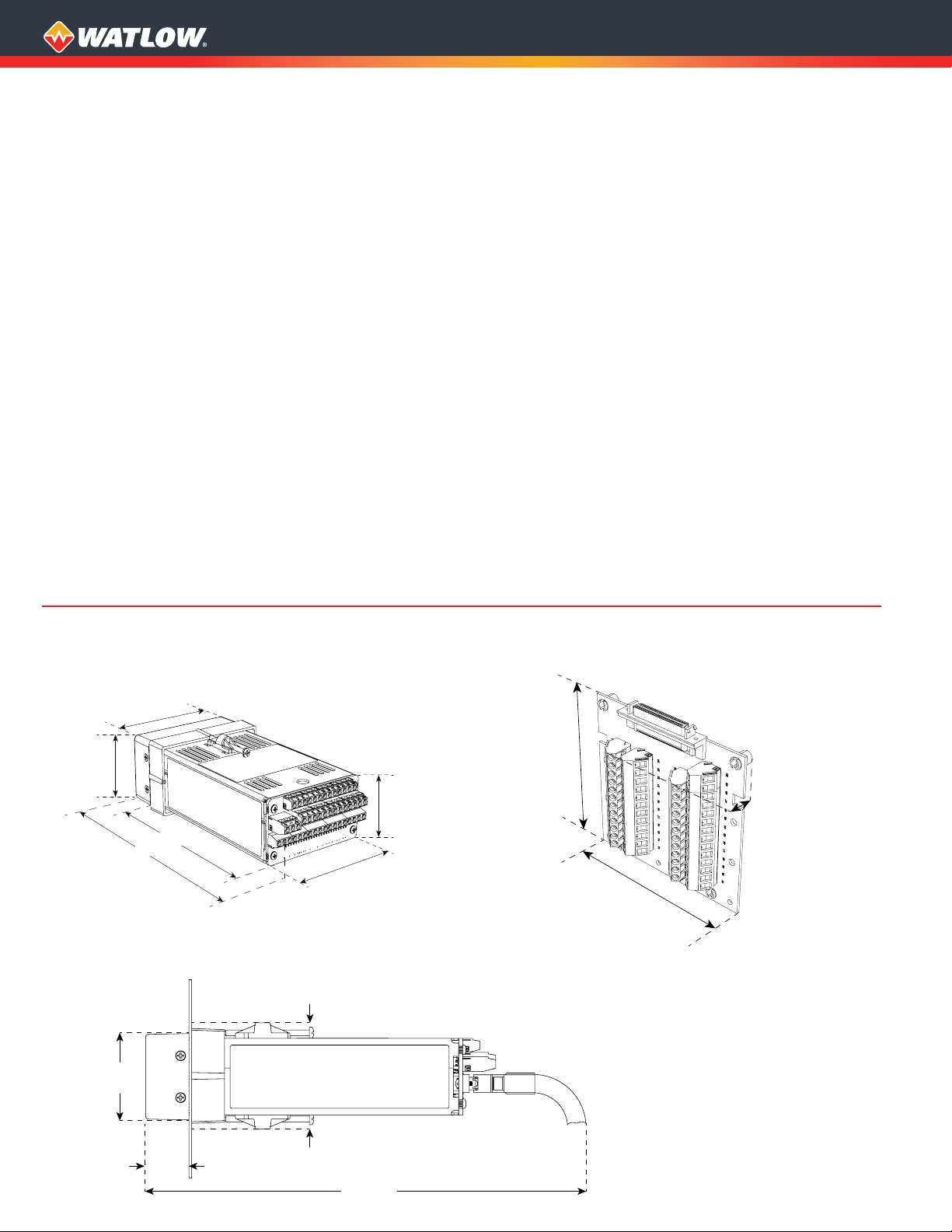
Dimensional Drawings
Figure 1 - TB18 Screw Terminals
Digital I/O Termination Option Shown
Figure 3 - Mass Termination (SCSI) Digital I/O Termination
and Cable Options
Figure 2 - TB50 Terminal Board Option
4.1 in.
(104 mm)
0.92 in.
(23 mm)
4.0 in.
(102 mm)
Note: Overall length in the application
depends on the Digital I/O Termination
option and bend radius of wiring and
cables used.
Page 3

CLS200 Specifications
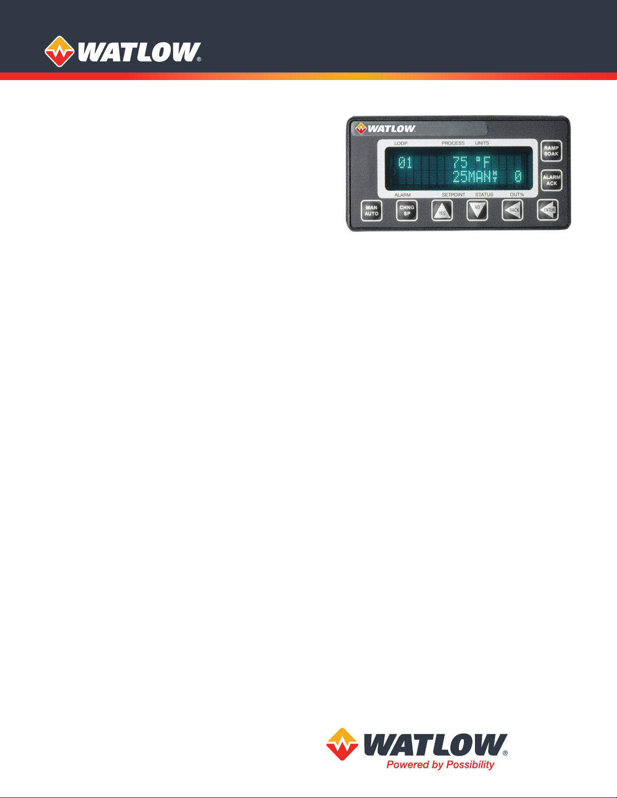
Operator Interface
• 32-character vacuum fluorescent display
• 8-key keypad to access guided menus and prompts,
enter passkey sequence, set values, switch between
single channel and multiple channel displays
• Controller configuration can be loaded via serial
communication
Analog Inputs
• 4-loop model: 4 differential inputs
• 8-loop model: 8 differential inputs
• 16-loop model: 16 single-ended inputs
Analog Over Voltage Protection
• ±20V referenced to digital ground
Maximum Common Mode Voltage
• 5V input to input or input to analog common
(4- and 8-loop models)
Common Mode Rejection (CMR)
• For inputs that do not exceed ±5V, >60dB dc to 1kHz and
120dB at selected line frequency
Noise Rejection
• 120dB at 60Hz
Sensors/Inputs
• Thermocouples: user-selectable type, direct connection,
linearization, reference junction compensation, reversed
and shorted thermocouple detection and upscale break
protection with output averaging
• RTD: (4 and 8 loop models only) 2- or 3-wire, platinum,
100Ω @ 0°C, DIN 0.003850Ω/Ω/°C curve, user-selectable
range. Two ranges offer different resolutions. Requires
scaling resistors. See ordering information.
• Linear: current and voltage signals from linear transmitters
• Pulse input
Input Range and Accuracy
Sensor Range (°C) Range (°F) Accuracy
Type B 66 to 1760°C 150 to 3200°F ±4.0°C
Type E -200 to 787°C -328 to 1448°F ±1.0°C
Type J -212 to 760°C -350 to 1400°F ±1.2°C
Type K -268 to 1371°C -450 to 2500°F ±1.3°C
Type R -18 to 1766°C 0 to 3210°F ±2.8°C
Type S -18 to 1760°C 0 to 3200°F ±2.8°C
Type T -268 to 399°C -450 to 750°F ±1.6°C
RTDs available on CLS204 and CLS208 only.
Sensor Range (°C) Range (°F) Accuracy
RTD1 -100 to 275˚C -148 to 527˚F ±1.1˚C
RTD2 -120 to 840˚C -184 to 1544˚F ±1.6˚C
Note: Accuracy @ 25˚C ambient. Valid for 10 to 100 percent
of span except Type B, which is specified for 800˚F to
3200˚F. RTD.
Linear Voltage and Current Inputs
Requires scaling resistors. See ordering information.
0-20mAVDC/4-20mAVDC
0-5VDC
0-10VDC
Temperature coefficient: 40ppm/°C
Other ranges available. Contact factory.
Pulse Input
• One TTL-level square wave input up to 2kHz
Input Sampling Rate at 60Hz
Each channel has the following scans per second:
• 4-loop model: 6 samples per second,
(update time: 0.167 sec.)
• 8-loop model: 3 samples per second,
(update time: 0.333 sec.)
• 16-loop model: 1.5 samples per second,
(update time: 0.667 sec.)
Internal Measurement Resolution
• 0.006 percent, greater than 14 bits
Calibration
• Automatic zero and full scale
Digital Inputs
• TTL-level used for selecting recipes or jobs, or R/S triggers
• 8 digital inputs and 1 pulse input with mass termination
(SCSI) digital I/O termination and TB50 terminal board
options
• 2 digital inputs and 1 pulse input with screw terminal
(TB18) digital I/O termination option
Digital Outputs
• 34 digital outputs with mass termination (SCSI) digital I/O
termination and TB50 terminal board options
• 11 control and alarm outputs with screw terminal (TB18)
digital I/O termination option
• 1 or 2 control outputs are user assigned for each loop
• Each control output can be configured for on-off time
proportioning, or distributed zero crossing
• Outputs sink up to 60mA each at 5VDC
• 350mA at 5VDC available from on-board supply
Alarm Outputs
• Independent process and deviation alarms for each
channel
• Alarms can operate any output not used for control
• User-programmable deadband, delay and startup
suppression
• Global alarm output activates when any alarm occurs
• Watchdog output indicates controller is functioning
correctly
Serial Interface
• EIA/TIA-232 or EIA/TIA-485
Baud Rate
• 2400, 9600 or 19200, user-selectable
Communications Protocols
• Form of ANSI X3.28-1976, (D1, F1) compatible with
Allen-Bradley PLC/2
• Modbus® RTU
Line Voltage/Power
• 15 to 24VDC ± 3VDC @ 1A (maximum),
300mA (no load)
Agency Approvals
• UL®, C-UL® listed: UL® 61010-1 safety requirements for
measurement, control and laboratory equipment
• CE Mark: See Declaration of Conformity for details
• RoHS by design
Page 4

Ordering Information
Instructions: Choose one option for each feature.
Number of Loops
4 loops
8 loops
16 loops
EIA/TIA-232
EIA/TIA-485, not terminated
EIA/TIA-485, terminated
Firmware
Standard
Ramp and soak
None
10-foot communication cable (DB-9 female/bare wires)
Enhanced features
Custom—contact factory
Plastic collar and screw clips
Digital I/O Termination
Screw terminals (TB18)
Mass termination (SCSI)
None
Contact factory
Digital I/O Termination Board Accessory
None
TB50 terminal board
Digital I/O Termination Cable Accessory
None
3-foot SCSI cable
3-foot SCSI cable with right angle connector
Standard units accept thermocouple on all loops.
Controllers can be equipped with resistors to scale signals for
various types of sensors. These resistors must be factory installed.
Contact your Watlow sales representative for other types of sensor.
Sixteen loop controllers cannot accept RTD sensors.
Note: To obtain a part number for your choice of options, communicate your selections to your Watlow sales representative who
will provide a part number to you.
Serial Communication Jumper Settings
Serial Communication Cable
Mounting Hardware
Customer Specific Options
Analog Input Scaling
Watlow® is a registered trademark of Watlow Electric Manufacturing Company.
UL® and cUL® are registered trademarks of Underwriter’s Laboratories, Inc.
Modbus® is a trademark of Schneider Automation Incorporated.
Powered by Possibility
To be automatically connected to the nearest
North American Technical Sales Oce:
1-800-WATLOW2 • www.watlow.com
inquiry@watlow.com
©2020 Watlow Electric Manufacturing Company all rights reserved.
International Technical Sales Offices:
Austria +43 6244 20129 0
China +86 21 3532 8532
France +33 1 41 32 79 70
Germany +49 7253 9400 0
India +91 40 6661 2700
Italy +39 02 458 8841
Japan +81 3 3518 6630
Korea +82 2 2169 2600
Mexico +52 442 256 2200
Singapore +65 6773 9488
Spain +34 91 675 1292
Taiwan +886 7 288 5168
UK +44 115 964 0777
WIN-UDCLS-0220
Page 5

Compact Loop System,
Providing Powerful Control
in a 1/8 DIN Package
SPECIFICATION SHEET
SERIES CLS200
Not for New Designs
This specication sheet is for the old version of the
SERIES CLS200 which is now “Not for new designs.”
Please see the specication sheet on the previous pages
for the replacement SERIES CLS200 for all new designs.
Watlow’s SERIES CLS200 is a powerful line of controllers,
combining performance and flexibility with compact design.
The 4, 8 and 16 loop versions provide complete controller
solutions for a broad range of applications. Support for
multiple types of sensor inputs is available, including
thermocouples, RTDs, linear voltage, current and frequency.
Each controller can operate as a stand-alone system, and
includes built-in serial communications for computer interface
and data acquisition. Optional programmable ramp and soak
features allow complex batch processing and sequencing.
An enhanced feature option offers cascade control, ratio
control, differential control, process variable retransmit and
remote analog set point.
The SERIES CLS200 controllers are UL® and C-UL® listed and
meet the requirements of the European Community EMC
Directive and carry the CE mark.
Features and Benefits
PID control of up to 16 heat and cool loops
• Minimizes panel space per loop
• Reduces installation time
• Increases reliability: fewer parts means fewer failures
Auto-tune
• Requires less time tuning
• Achieves excellent control with less expertise
Menu-guided operation with full text display
• Allows quick setup of the controller
• Simplies operation
Eight jobs stored and recalled
• Changes quickly from one process to another
Multiple and mixed inputs
• Accepts combinations of thermocouples, RTDs, linear dc
voltage and linear dc current sensors
• Reduces learning curve and inventory
Sensor failure detection
• Reduces time troubleshooting reversed, shorted and
open sensors
High/low process and deviation alarms for each input
• Integrates as needed to integrate with PLC and other
control elements
34 digital outputs
• Provides exible conguration
• Allows use of outputs as needed for control and alarms
EIA/TIA-232 and 485 communications
• Connects to software for easy conguration and operation
• Allows integration with controllers and software
SUPERCEDED
Page 6

DAC and SDAC Modules
1.96 in.
(50 mm)
3.78 in.
(96 mm)
(25 mm)
(178 mm)
(13 mm)
(13 mm)
(41 mm)
1 in.
7 in. 1.6 in.*
0.5 in.0
0.5 in.
Bezel
Steel Case
Terminals
SCSI Cable
(not used with TB-18)
*0.60 in. (15 mm) with Right Angle SCSI Connector
The optional DAC and SDAC modules are available for
Watlow SERIES CLS200 controllers.
DAC
The DAC (digital to analog converter) converts one or two
of the controller’s distributed zero crossing (DZC) output
signals to analog signals. Each output is field configurable
for 4-20mVDC, 0-5VDC or 0-10VDC.
SDAC
The SDAC (serial digital to analog converter) converts
one controller output to a precise analog voltage or
current signal. The unit is typically used for process variable
retransmit, open-loop control, motor or belt speed control,
or phase-angle fired SCR power controllers. The SDAC bears
the CE mark and is UL® and C-UL® listed.
Firmware Options
Choose firmware with the features needed for the
application:
• Standard—includes closed-loop PID control, auto-tune,
alarms, job memory and failed sensor detection.
• Ramp and soak—includes the standard firmware
features with the addition of ramp and soak and process
variable retransmit. Each channel can be configured for
standard PID control or ramp and soak operation. Unused
control outputs on any channel can be configured for
retransmition.
• Enhanced features— includes the standard firmware
features with the addition of process variable retransmit,
remote analog set point, cascade control, ratio control
and differential control algorithms. Each channel can be
configured for standard PID controller or one of the other
control algorithms. Each channel of cascade control or
remote analog set point requires two controller channels.
Unused control outputs on any channel can be
configured for retransmit.
Because the SERIES CLS200 has no onboard analog
outputs, applications that use process variable retransmit
typically require one SDAC module per retransmitted
signal.
D
SUPERCEDE
Page 7

CLS200 Specifications
Operator Interface
• 32-character vacuum fluorescent display
• 8-key keypad to access guided menus and prompts,
enter passkey sequence, set values, switch between
single channel and multiple channel displays
• Controller configuration can be loaded through the
standard serial port
Analog Inputs
• CLS204 4 differential
• CLS208 8 differential
• CLS216 16 single-ended
Noise Rejection
• 120dB at 60Hz
Temperature Coefficient
• 40ppm/°C
Sensors/Inputs
• Thermocouples: user-selectable type, direct connection,
linearization, reference junction compensation, reversed
and shorted thermocouple detection and upscale break
protection with output averaging
• RTD: (CLS204 and CLS208 only) 2- or 3-wire, platinum,
100Ω @ 0°C, DIN 0.003850Ω/Ω/°C curve, user-selectable
range. Two user-selectable ranges offer different resolutions. Requires scaling resistors. See special/linear
inputs in ordering information.
• Linear: current and voltage signals from linear transmitters
• Pulse input
Input Range and Accuracy
Sensor Range (°C) Range (°F) Accuracy
Type B 66 to 1760°C 150 to 3200°F ±4.0°C
Type E -200 to 787°C -328 to 1448°F ±1.0°C
Type J -212 to 760°C -350 to 1400°F ±1.2°C
Type K -268 to 1371°C -450 to 2500°F ±1.3°C
Type R -18 to 1766°C 0 to 3210°F ±2.8°C
Type S -18 to 1760°C 0 to 3200°F ±2.8°C
Type T -268 to 399°C -450 to 750°F ±1.6°C
RTDs available on CLS204 and CLS208 only.
Sensor Range (°C) Range (°F) Accuracy
RTD1 -100 to 275˚C -148 to 527˚F ±1.1˚C
RTD2 -120 to 840˚C -184 to 1544˚F ±1.6˚C
Note: Accuracy @ 25˚C ambient. Valid for 10 to 100 percent
of span except Type B, which is specified for 800˚F to
3200˚F. RTD.
Linear Voltage and Current Inputs
Requires scaling resistors. See special inputs in ordering
information.
0-20mAVDC/4-20mAVDC
0-5VDC
0-10VDC
Other ranges available. Consult factory.
SUPERCEDED
Pulse Input
• One TTL-level square wave input up to 2kHz
Input Sampling Rate at 60Hz
Each channel has the following scans per second:
• CLS204: 6 samples per second (update time: 0.167 sec.)
• CLS208: 3 samples per second, (update time: 0.333 sec.)
• CLS216: 1.5 samples per second, (update time: 0.667 sec.)
Internal Measurement Resolution
• 0.006 percent, greater than 14 bits
Calibration
• Automatic zero and full scale
Digital Inputs
• TTL-level used for selecting recipes or jobs, or R/S triggers
• 8 inputs and 1 pulse input with 50-pin terminal board
option
• 2 inputs and pulse input or 3 inputs with 18-pin terminal
block option
Digital Outputs
• 34 digital outputs are available with 50-pin terminal
board option
• 10 control outputs with 18-pin terminal block option
• 1 or 2 control outputs are user assigned for each loop
• Each control output can be configured for on-off time
proportioning, or distributed zero crossing
• Outputs sink up to 60mA each at 5VDC
• 350mA at 5VDC available from on-board supply
Alarm Outputs
• Independent process and deviation alarms for each
channel
• Alarms can operate any output not used for control
• User-programmable deadband, delay and startup
suppression
• Global alarm output activates when any alarm occurs
• Watchdog output indicates controller is functioning
correctly
Serial Interface
• EIA/TIA-232 or EIA/TIA-485
Baud Rate
• 2400, 9600 or 19200, user-selectable
Communications Protocols
• Form of ANSI X3.28-1976, (D1, F1) compatible with
Allen-Bradley PLC/2
• Modbus® RTU
Line Voltage/Power
• 15 to 24VDC ± 3VDC @ 1A (maximum),
300mA (no load)
Agency Approvals
• UL®, C-UL® listed: UL® 61010-1 safety requirements for
measurement, control and laboratory equipment
• CE Mark: See Declaration of Conformity for details
Page 8

Ordering Information
SERIES CLS200 Part Number
①
② ③
Number
of
Channels
2
④
Controller
Type
⑤
Terminal
Board
⑥
Power
Supply
⑦
SCSI
Cables
⑧
Serial
Comm.
Cables
⑨
Serial
Comm.
Jumper Settings
⑩ ⑪
Special
Inputs and Other
Custom Options
② ③
04 = 4 channel
08 = 8 channel
16 = 16 channel
④
Standard EPROM
1 =
Ramp and Soak
3 =
Enhanced features
4 =
Custom rmware
C =
⑤
0 = SCSI connector only, user supplies cable and terminal board
1 = 18-pin terminal block (CLS204 and CLS208 only)
2 = 50-pin terminal block (includes 3 foot SCSI cable)
⑥
0 = No power supply
120/240VAC, 50/60Hz power supply adapter (15VDC @ 1.2A)
3 =
CE, UL® Class 2 approved
Number of Channels
Controller Type
Terminal Board
Power Supply
Ordering Information
Special Input Type
① ② ③ ④ ⑤
CLSSI
⑥ ⑦
Special
Input
Type
⑧
Start
Channel
⑨
End
Channel
⑦
3 foot SCSI cable with terminal board option 2 (no cable
0 =
with options 0 or 1)
2 = 3 foot right angle SCSI cable
⑧
0 = No serial communication cable
1 = 10 foot serial communication cable (DB-9 female/bare wire)
⑨
0 = EIA/TIA-232
1 = EIA/TIA-485
2 = EIA/TIA-485 terminated
⑩ ⑪
(Standard unit supports thermocouples and -10 to 60mV linear
inputs. For other sensors, order special inputs. See below for
ordering instructions. For CLS216 specify two digits, for CLS204 and
CLS208 specify one digit.
0 or 00 = Thermocouples and -10 to 60mV inputs only
N or NN = Number of current, voltage or RTD inputs (N is number)
XX = Factory assigned custom code (XX is two alphabetic characters)
Serial Communication Cables
Serial Communication Jumper Settings
Special Inputs and Other Custom Options
SCSI Cables
Ordering Information
DAC/SDAC
① ② ③
DAC
④
Special
Input
Type
⑤
Start
Channel
⑥ ⑦
Not required for thermocouple sensor inputs.
RTD 1: 0.1°, -148 to 527°F (-100 to 275°C) (Not available on
20 =
CLS216)
RTD 2: 1°, -184 to 1544°F (-120 to 840°C) (Not available on
21 =
CLS216)
0-20mA dc/4-20mA dc
44 =
0-5VDC
55 =
0-10VDC
56 =
⑧
XX = Channel Number XX
⑨
XX = Channel Number XX
Availability: Up to four weeks, depending on complexity and order
release quantity. Contact factory for details.
Special Input Type
Start Channel
End Channel
Powered by Possibility
To be automatically connected to the nearest
North American Technical Sales Oce:
1-800-WATLOW2 • www.watlow.com
©2019 Watlow Electric Manufacturing Company all rights reserved.
SUPERCEDED
International Technical Sales Offices:
Austria +43 6244 20129 0
China +86 21 3532 8532
France +33 1 41 32 79 70
Germany +49 7253 9400 0
④
DAC with 2 each 0 to 5VDC outputs
1 =
DAC with 2 each 0 to 10VDC outputs
2 =
DAC with 2 each 4 to 20mA dc outputs
3 =
Serial digital to analog converter (SDAC)
4 =
⑤
None
A =
120/240VAC, 50/60Hz power supply adapter, (15VDC @ 1.2A)
H =
powers up to 12 dual DAC modules
120/240VAC, 50/60HZ power supply adapter (5VDC @ 3A)
L =
powers up to 10 SDAC modules
Watlow® is a registered trademark of Watlow Electric Manufacturing Company.
Windows® is a registered trademark of Microsoft Corporation.
UL® and C-UL® are registered trademarks of Underwriter’s Laboratories, Inc.
Modbus® is a registered trademark of AEG Schneider Automation.
India +91 40 6661 2700
Italy +39 02 458 8841
Japan +81 3 3518 6630
Korea +82 2 2169 2600
DAC/SDAC Type
Power Supply
Mexico +52 442 256 2200
Singapore +65 6773 9488
Spain +34 91 675 1292
Taiwan +886 7 288 5168
UK +44 115 964 0777
WIN-CLS-1219
 Loading...