

Page 1

CLS200 Series
User’s Guide
Watlow
1241 Bundy Boulevard
Winona, MN 55987
Customer Service:
Phone........1-800-414-4299
Fax.............1-800-445-8992
Technical Support:
Phone........+1 (507) 494-5656
Fax ............+1 (507) 452-4507
Email .........wintechsupport@watlow.com
Part No. 0600-3050-2000 Rev. A
November 2008
Page 2

Copyright © 1998-2003, Watlow Anafaze
Information in this manual is subject to change without notice. No part of this publication may be reproduced, stored in a retrieval system, or transmitted in any form
without written permission from Watlow Anafaze.
Warranty
Watlow Anafaze, Incorporated warrants that the products furnished under this Agreement will be free from defects in material and workmanship for a period of three years
from the date of shipment. The Customer shall provide notice of any defect to Watlow
Anafaze, Incorporated within one week after the Customer's discovery of such defect.
The sole obligation and liability of Watlow Anafaze, Incorporated under this warranty
shall be to repair or replace, at its option and without cost to the Customer, the defective product or part.
Upon request by Watlow Anafaze, Incorporated, the product or part claimed to be
defective shall immediately be returned at the Customer's expense to Watlow Anafaze,
Incorporated. Replaced or repaired products or parts will be shipped to the Customer
at the expense of Watlow Anafaze, Incorporated.
There shall be no warranty or liability for any products or parts that have been subject to misuse, accident, negligence, failure of electric power or modification by the
Customer without the written approval of Watlow Anafaze, Incorporated. Final determination of warranty eligibility shall be made by Watlow Anafaze, Incorporated. If a
warranty claim is considered invalid for any reason, the Customer will be charged for
services performed and expenses incurred by Watlow Anafaze, Incorporated in handling and shipping the returned unit.
If replacement parts are supplied or repairs made during the original warranty
period, the warranty period for the replacement or repaired part shall terminate with
the termination of the warranty period of the original product or part.
The foregoing warranty constitutes the sole liability of Watlow Anafaze, Incorporated
and the Customer's sole remedy with respect to the products. It is in lieu of all other
warranties, liabilities, and remedies. Except as thus provided, Watlow Anafaze, Inc.
disclaims all warranties, express or implied, including any warranty of merchantability or fitness for a particular purpose.
Please Note: External safety devices must be used with this equipment.
Page 3

Table of Contents
List of Figures xi
List of Tables xv
1 System Overview 1
Manual Contents 1
Getting Started 2
Safety Symbols 2
Initial Inspection 2
Product Features 3
CLS200 Parts List 5
Technical Description 7
CLS200 7
TB50 8
CLS200 Cabling 9
Safety 9
External Safety Devices 9
Power-Fail Protection 10
2 Installation 11
Typical Installation 12
Mounting Controller Components 12
Recommended Tools 13
Mounting the Controller 13
Mounting the TB50 16
Mounting the Power Supply 18
Mounting the Dual DAC or Serial DAC Module 19
System Wiring 21
Wiring Recommendations 21
Noise Suppression 22
Ground Loops 24
Power Connections 25
Wiring the Power Supply 25
Connecting TB50 to CLS200 27
Testing Your System 28
TB50 or TB18 Test 28
Digital Output Test 28
Digital Input Test 29
Doc.# 0600-3050-2000 Watlow Anafaze iii
Page 4

Table of Contents CLS200 Series User’s Guide
Sensor Wiring 29
Input Wiring Recommendations 30
Thermocouple Connections 31
RTD Input Connections 32
Reference Voltage Terminals 32
Voltage Input Connections 32
Current Input Connections 33
Pulse Input Connections 34
Wiring Control and Digital I/O 35
Output Wiring Recommendations 35
Cable Tie Wraps 35
Digital Outputs 35
Digital Inputs 38
TB18 Connections (CLS204 and CLS208 Only) 40
TB50 Connections 41
Analog Outputs 43
Wiring the Dual DAC 43
Wiring the Serial DAC 44
Serial Communications 45
EIA/TIA-232 Interface 45
EIA/TIA-485 Interface 47
EIA/TIA-485 Converters and Laptop Computers 49
3 Using the CLS200 51
Front Panel 52
Front Panel Keys 53
Displays 55
Bar Graph Display 55
Single Loop Display 57
Alarm Displays 58
System Alarms 60
Job Display 60
Changing the Setpoint 61
Selecting the Control Status 61
Manual and Automatic Control 61
Autotuning a Loop 62
Using Alarms 64
Alarm Delay 64
Failed Sensor Alarms 65
Process Alarms 66
Global Alarm 68
Ramp/Soak 69
4 Setup 71
How to Access the Setup Menus 71
How to Change a Parameter 72
Setup Global Parameters Menu
Load Setup From Job 75
Save Setup to Job 75
Job Select Digital Inputs 76
74
iv Watlow Anafaze Doc.# 0600-3050-2000
Page 5

CLS200 Series User’s Guide Table of Contents
Job Select Digital Inputs Active 77
Output Override Digital Input 77
Override Digital Input Active 77
Startup Alarm Delay 78
Keyboard Lock Status 78
Power Up Output Status 78
Process Power Digital Input 79
Controller Address 79
Communications Baud Rate 80
Communications Protocol 80
Communications Error Checking 80
AC Line Frequency 81
Digital Output Polarity on Alarm 81
EPROM Information 81
Setup Loop Input Menu 82
Input Type 83
Loop Name 84
Input Units 84
Input Reading Offset 84
Reversed T/C Detection 85
Input Pulse Sample Time 85
Linear Scaling Parameters 86
Input Filter 89
Setup Loop Control Parameters Menu 90
Heat or Cool Control PB 91
Heat or Cool Control TI 91
Heat or Cool Control TD 91
Heat or Cool Output Filter 91
Spread 92
Restore PID Digital Input 92
Setup Loop Outputs Menu 93
Enable or Disable Heat or Cool Outputs 94
Heat or Cool Output Type 94
Heat or Cool Cycle Time 95
SDAC Mode 95
SDAC Low Value 95
SDAC High Value 95
Heat or Cool Output Action 96
Heat or Cool Output Limit 96
Heat or Cool Output Limit Time 96
Sensor Fail Heat or Cool Output 97
Heat or Cool Thermocouple Break Output Average 97
Heat or Cool Linearity 98
Setup Loop Alarms Menu 99
High Process Alarm Setpoint 100
High Process Alarm Type 100
High Process Alarm Output Number 100
Deviation Alarm Value 100
High Deviation Alarm Type 101
High Deviation Alarm Output Number 101
Low Deviation Alarm Type 101
Low Deviation Alarm Output Number 101
Low Process Alarm Setpoint 102
Doc.# 0600-3050-2000 Watlow Anafaze v
Page 6

Table of Contents CLS200 Series User’s Guide
Low Process Alarm Type 102
Low Process Alarm Output Number 102
Alarm Deadband 102
Alarm Delay 103
Manual I/O Test 103
Digital Inputs 103
Test Digital Output 104
Digital Output Number 104
Keypad Test 105
Display Test 105
5 Extruder Control 107
Setup Loop Outputs Menu 107
Cool Output Nonlinear Output Curve 107
Defaults 108
Extruder Control Algorithm 110
6 Enhanced Features 111
Process Variable Retransmit 113
Setup Loop Process Variable Retransmit Menu 113
Process Variable Retransmit Example: Data Logging 115
Cascade Control 118
Setup Loop Cascade Menu 119
Cascade Control Example: Water Tank 121
Ratio Control 124
Setup Loop Ratio Control Menu 125
Ratio Control Example: Diluting KOH 126
Remote Analog Setpoint 129
Remote Analog Setpoint Example: Setting a Setpoint with a PLC 129
Differential Control 131
Differential Control Example: Thermoforming 131
7 Ramp/Soak 133
Features 134
Ramp/Soak Menus 136
Setup Global Parameters Menu 137
Ramp/Soak Time Base 137
Setup Ramp/Soak Profile Menu 137
Edit Ramp/Soak Profile 137
Copy Setup From Profile 138
Tolerance Alarm Time 138
Ready Segment Setpoint 138
Ready Segment Edit Events 139
External Reset Input Number 139
Edit Segment Number 140
Segment Time 140
Segment Setpoint 140
Edit Segment Events 141
Edit Segment Triggers 142
Segment Tolerance 143
vi Watlow Anafaze Doc.# 0600-3050-2000
Page 7

CLS200 Series User’s Guide Table of Contents
Last Segment 144
Repeat Cycles 144
Setpoints and Tolerances for Various Input Types 144
Using Ramp/Soak 145
Ramp/Soak Displays 146
Assigning a Profile to a Loop 148
Running a Profile 148
Holding a Profile or Continuing from Hold 150
Responding to a Tolerance Alarm 151
Resetting a Profile 151
In Case of a Power Failure 152
8 Tuning and Control 153
Control Algorithms 153
On/Off Control 154
Proportional Control 154
Proportional and Integral Control 155
Proportional, Integral and Derivative Control 155
Heat and Cool Outputs 156
Control Outputs 157
Output Control Signals 157
Output Filter 158
Reverse and Direct Action 159
Setting Up and Tuning PID Loops 159
Proportional Band (PB) Settings 159
Integral Settings 160
Derivative Settings 160
General PID Constants by Application 161
Proportional Band Only (P) 161
Proportional with Integral (PI) 161
PI with Derivative (PID) 161
9 Troubleshooting and Reconfiguring 163
When There is a Problem 163
Returning Your Unit 164
Troubleshooting Controllers 164
Process and Deviation Alarms 164
Failed Sensor Alarms 166
System Alarms 166
Other Behaviors 167
Corrective and Diagnostic Procedures 168
Low Power 168
Battery Dead 168
Ambient Warning 168
H/W Ambient Failure 169
H/W Gain or Offset Failure 170
Keys Do Not Respond 170
Checking Analog Inputs 171
Earth Grounding 172
Checking Control Outputs 172
Testing Control Output Devices 173
Doc.# 0600-3050-2000 Watlow Anafaze vii
Page 8

Table of Contents CLS200 Series User’s Guide
Testing the TB18 and TB50 173
Testing Control and Digital Outputs 173
Testing Digital Inputs 173
Additional Troubleshooting for Computer Supervised Systems 174
Computer Problems 174
Communications 175
Ground Loops 175
Software Problems 176
NO-Key Reset 176
Replacing the EPROM 176
Changing Communications 179
Installing Scaling Resistors 180
CLS204 and CLS208 Input Circuit 180
CLS204 and CLS208 Current Inputs 181
CLS204 and CLS208 Voltage Inputs 182
CLS204 and CLS208 RTDs and Thermistors 183
CLS216 Input Circuit 184
CLS216 Current Inputs 184
CLS216 Voltage Inputs 185
Scaling and Calibration 186
Configuring Dual DAC Outputs 186
Configuring Serial DAC Outputs 188
10 Linear Scaling Examples 189
Example 1: A 4-to-20 mA Sensor 189
Î
Example 2: A 0-to-5V
(dc) Sensor 191
Example 3: A Pulse Encoder 192
11 Specifications 193
CLS200 System Specifications 193
CLS200 Processor Physical Specifications 194
TB50 Physical Specifications 196
Inputs 200
Outputs 202
CLS200 Power Supply 205
Dual DAC Specifications 207
Dual DAC Inputs 208
Dual DAC Analog Outputs 208
Serial DAC Specifications 209
Serial DAC Inputs 210
Serial DAC Analog Outputs 211
Glossary 213
Index 221
Menu Structure 233
Declaration of Conformity 234
viii Watlow Anafaze Doc.# 0600-3050-2000
Page 9

1 System Overview
Figure 1.1—CLS200 Part Numbering 5
Figure 1.2—CLS200 Special Inputs Parts List 6
Figure 1.3—CLS200 Rear Views 7
Figure 1.4—CLS200 Front Panel 8
Figure 1.5—TB50 8
List of Figures
2 Installation
Figure 2.1—CLS200 System Components 12
Figure 2.2—Clearance with Straight SCSI Cable 14
Figure 2.3—Clearance with Right-Angle SCSI Cable 14
Figure 2.4—Wiring Clearances 15
Figure 2.5—Mounting Bracket 16
Figure 2.6—Mounting the TB50 16
Figure 2.7—TB50 Mounted on a DIN Rail (Front) 17
Figure 2.8—TB50 Mounted on DIN Rail (Side) 17
Figure 2.9—Mounting a TB50 with Standoffs 18
Figure 2.10—CLS200 Power Supply Mounting Bracket 19
Figure 2.11—Dual DAC and Serial DAC Dimensions 20
Figure 2.12—CLS200 Series Controller with TB18 25
Figure 2.13—CLS200 Series Controller with TB50 25
Figure 2.14—Power Connections with the CLS200 Power Supply 27
Figure 2.15—CLS200 Connector Locations 30
Figure 2.16—Thermocouple Connections 31
Figure 2.17—RTD Connections to CLS204 or CLS208 32
Figure 2.18—Linear Voltage Signal Connections 33
Figure 2.19—Linear Current Signal Connections 33
Figure 2.20—Encoder with 5V Î (dc) TTL Signal 34
Figure 2.21—Encoder Input with Voltage Divider 34
Figure 2.22—Digital Output Wiring 36
Figure 2.23—Sample Heat, Cool and Alarm Output Connections 37
Figure 2.24—Output Connections Using External Power Supply 38
Figure 2.25—TB50 Watchdog Timer Output 38
Figure 2.26—TB18 Watchdog Timer Output 38
Figure 2.27—Wiring Digital Inputs 39
Figure 2.28—Dual DAC with Current Output 43
Figure 2.29—Dual DAC with Voltage Output 44
Doc.# 0600-3050-2000 Watlow Anafaze ix
Page 10

List of Figures CLS200 Series User’s Guide
Figure 2.30—Single/Multiple Serial DACs 45
Figure 2.31—Connecting One CLS200 to a Computer Using EIA/TIA-232 46
Figure 2.32—EIA/TIA-485 Wiring 47
Figure 2.33—Recommended System Connections 48
3 Using the CLS200
Figure 3.1—Operator Displays 51
Figure 3.2—CLS200 Front Panel 52
Figure 3.3—Bar Graph Display 55
Figure 3.4—Single Loop Display 57
Figure 3.5—Single Loop Display, Heat and Cool Outputs Enabled 57
Figure 3.6—Single Loop Display with a Process Alarm 58
Figure 3.7—Failed Sensor Alarm in the Single Loop Display 58
Figure 3.8—Alarm Symbols in the Bar Graph Display 58
Figure 3.9—Activation and Deactivation of Process Alarms 68
4 Setup
Figure 4.1—CLS200 Menu Tree 73
Figure 4.2—Two Points Determine Process Variable Conversion 86
Figure 4.3—Process Variable Limited by Input Reading Range 87
Figure 4.4—Linear and Nonlinear Outputs 98
Figure 4.5—Digital Inputs Screen 104
5 Extruder Control
Figure 5.1—Cool Output Nonlinear Output Curve 108
6 Enhanced Features
Figure 6.1—Enhanced Features Option Menus 112
Figure 6.2—Linear Scaling of Process Variable for Retransmit 115
Figure 6.3—Application Using Process Variable Retransmit 116
Figure 6.4—Relationship Between the Primary Loop’s Output and the Secondary
Loop’s Setpoint 119
Figure 6.5—Application Using Cascade Control 121
Figure 6.6—Secondary Loop Setpoint Related to Primary Loop Output 123
Figure 6.7—Relationship Between the Master Loop’s Process Variable and the Ratio
Loop’s Setpoint 124
Figure 6.8—Application Using Ratio Control 127
7 Ramp/Soak
Figure 7.1—Sample Ramp/Soak Profile 133
Figure 7.2—Setup Ramp/Soak Profiles Menu 136
Figure 7.3—Positive and Negative Tolerances 143
Figure 7.4—Ramp/Soak Screens 145
x Watlow Anafaze Doc.# 0600-3050-2000
Page 11

CLS200 Series User’s Guide List of Figures
8 Tuning and Control
Figure 8.1—On/Off Control 154
Figure 8.2—Proportional Control 155
Figure 8.3—Proportional and Integral Control 155
Figure 8.4—Proportional, Integral and Derivative Control 156
Figure 8.5—Time Proportioning and Distributed Zero Crossing Waveforms 157
9 Troubleshooting and Reconfiguring
Figure 9.1—Removal of Electronics Assembly from Case 177
Figure 9.2—Screws Locations on PC Board 178
Figure 9.3—EPROM Location 178
Figure 9.4—Remove EPROM 178
Figure 9.5—Jumper Configurations 179
Figure 9.6—CLS204 and CLS208 Input Circuit 181
Figure 9.7—CLS216 Input Circuit 184
Figure 9.8—Dual DAC 187
Figure 9.9—Serial DAC Voltage/Current Jumper Positions 188
11 Specifications
Figure 11.1—CLS200 Processor Module Dimensions 194
Figure 11.2—CLS200 Clearances with Straight SCSI Cable 195
Figure 11.3—CLS200 Clearances with Right-Angle SCSI Cable 195
Figure 11.4—TB50 Dimensions 197
Figure 11.5—TB50 Dimensions with Straight SCSI Cable 198
Figure 11.6—TB50 Dimensions with Right-Angle SCSI Cable 199
Figure 11.7—Power Supply Dimensions (Bottom View) 206
Figure 11.8—Dual DAC Dimensions 207
Figure 11.9—Serial DAC Dimensions 209
Doc.# 0600-3050-2000 Watlow Anafaze xi
Page 12

List of Figures CLS200 Series User’s Guide
xii Watlow Anafaze Doc.# 0600-3050-2000
Page 13

2 Installation
Table 2.1—Cable Recommendations 22
Table 2.2—Power Connections 26
Table 2.3—Digital Output States and Values Stored in the Controller 36
Table 2.4—Digital Inputs States and Values Stored in the Controller 39
Table 2.5—TB18 Connections 40
Table 2.6—TB50 Connections for CLS204 and CLS208 41
Table 2.7—TB50 Connections for CLS216 42
Table 2.8—EIA/TIA-232 Connections 46
Table 2.9—RTS/CTS Pins in DB-9 and DB-25 Connectors 46
List of Tables
3 Using the CLS200
Table 3.1—Bar Graph Display Symbols 55
Table 3.2—Control Status Symbols on the Bar Graph and Single Loop Displays 56
Table 3.3—Alarm Type and Symbols 59
4 Setup
Table 4.1—Global Parameters 74
Table 4.2—Job Select Inputs 76
Table 4.3—Job Selected for Various Input States 76
Table 4.4—Firmware Option Codes 81
Table 4.5—Setup Loop Input 82
Table 4.6—CLS200 Input Types and Ranges 83
Table 4.7—Input Character Sets 84
Table 4.8—Input Reading Offset 85
Table 4.9—Display Formats 87
Table 4.10—Setup Loop Control Parameters 90
Table 4.11—Setup Loop Outputs 93
Table 4.12—Heat / Cool Output Types 94
Table 4.13—Setup Loop Alarms 99
Table 4.14—Manual I/O Test 103
5 Extruder Control
Table 5.1—Default Control Parameters for Fan Cool Output 109
Table 5.2—Default Control Parameters for Oil Cool Output 109
Table 5.3—Default Control Parameters for H2O Cool Output 109
Doc.# 0600-3050-2000 Watlow Anafaze xiii
Page 14

List of Tables CLS200 Series User’s Guide
6 Enhanced Features
Table 6.1—Application Example: Setting Up Process Variable Retransmit 117
Table 6.2—Application Example: Setting Up Cascade Control 122
Table 6.3—Application Example: Setting Up Ratio Control 128
Table 6.4—Application Example: Setting Up Remote Setpoint 130
Table 6.5—Application Example: Setting Up Differential Control 132
7 Ramp/Soak
Table 7.1—Ramp/Soak Specifications 135
Table 7.2—Trigger Latch Logic 143
Table 7.3—Display Formats 145
Table 7.4—Ramp/Soak Single Loop Display 146
Table 7.5—Ramp/Soak Control Status Symbols 147
Table 7.6—Ramp/Soak Profile Modes 150
8 Tuning and Control
Table 8.1—Proportional Band Settings 159
Table 8.2—Integral Term and Reset Settings 160
Table 8.3—Derivative Term Versus Rate 160
Table 8.4—General PID Constants 162
9 Troubleshooting and Reconfiguring
Table 9.1—Controller Alarm Codes for Process and Deviation Alarms 164
Table 9.2—Operator Response to Alarms 165
Table 9.3—Failed Sensor Alarm Codes 166
Table 9.4—Hardware Error Messages 166
Table 9.5—Other Symptoms 167
Table 9.6—Resistor Values for CLS204 and CLS208 Current Inputs 181
Table 9.7—Resistor Locations for CLS204 and CLS208 Current Inputs 181
Table 9.8—Resistor Values for CLS204 and CLS208 Voltage Inputs 182
Table 9.9—Resistor Locations for CLS204 and CLS208 Voltage Inputs 182
Table 9.10—Resistor Values for CLS204/208 RTD and Thermistor Inputs 183
Table 9.11—Resistor Locations for CLS204/208 RTD and Thermistor Inputs 183
Table 9.12—Resistor Values for CLS216 Current Inputs 184
Table 9.13—Resistor Locations for CLS216 Current Inputs 185
Table 9.14—Resistor Values for CLS216 Voltage Inputs 185
Table 9.15—Resistor Locations for CLS216 Voltage Inputs 186
Table 9.16—Dual DAC Jumper Settings 187
10 Linear Scaling Examples
Table 10.1—Input Readings 190
Table 10.2—Scaling Values 190
Table 10.3—Input Readings and Calculations 191
Table 10.4—Scaling Values 191
Table 10.5—Scaling Values 192
xiv Watlow Anafaze Doc.# 0600-3050-2000
Page 15

CLS200 Series User’s Guide List of Tables
11 Specifications
Table 11.1—Agency Approvals / Compliance 193
Table 11.2—Environmental Specifications 194
Table 11.3—Physical Dimensions 194
Table 11.4—Processor with Straight SCSI 195
Table 11.5—Processor with Right Angle SCSI 195
Table 11.6—Processor Connections 196
Table 11.7—TB50 Physical Dimensions 196
Table 11.8—TB50 Connections 197
Table 11.9—TB50 with Straight SCSI 198
Table 11.10—TB50 with Right Angle SCSI 199
Table 11.11—Analog Inputs 200
Table 11.12—Pulse Inputs 201
Table 11.13—Thermocouple Range and Resolution 201
Table 11.14—RTD Range and Resolution 201
Table 11.15—Input Resistance for Voltage Inputs 202
Table 11.16—Digital Inputs 202
Table 11.17—Digital Outputs Control / Alarm 203
Table 11.18—CPU Watchdog Output 203
Table 11.19—5V Î (dc) Output (Power to Operate Solid-State Relays) 204
Table 11.20—Reference Voltage Output (Power to Operate Bridge Circuit
Sensors) 204
Table 11.21—Processor Serial Interface 204
Table 11.22—Processor Power Requirements 204
Table 11.23—Power Supply Environmental Specifications 205
Table 11.24—Power Supply Agency Approvals / Compliance 205
Table 11.25—Power Supply Physical Specifications 205
Table 11.26—Power Supply with Mounting Bracket 205
Table 11.27—Power Supply Inputs 206
Table 11.28—Power Supply Outputs 206
Table 11.29—Dual DAC Environmental Specifications 207
Table 11.30—Dual DAC Physical Specifications 207
Table 11.31—Dual DAC Power Requirements 208
Table 11.32—Dual DAC Specifications by Output Range 208
Table 11.33—Serial DAC Environmental Specifications 209
Table 11.34—Serial DAC Physical Specifications 209
Table 11.35—Serial DAC Agency Approvals / Compliance 210
Table 11.36—Serial DAC Inputs 210
Table 11.37—Serial DAC Power Requirements 210
Table 11.38—Serial DAC Analog Output Specifications 211
Doc.# 0600-3050-2000 Watlow Anafaze xv
Page 16

List of Tables CLS200 Series User’s Guide
xvi Watlow Anafaze Doc.# 0600-3050-2000
Page 17

1
System Overview
Manual Contents
This manual describes how to install, set up, and operate a
CLS204, CLS208 or CLS216 controller. Each chapter covers a different aspect of your control system and may apply
to different users:
• Chapter 1: System Overview provides a component
list and summary of features for the CLS200 series
controllers.
• Chapter 2: Installation provides detailed instructions on installing the CLS200 series controller and its
peripherals.
• Chapter 3: Using the CLS200 provides an overview
of operator displays used for system monitoring and
job selection.
• Chapter 4: Setup provides detailed descriptions of
all menus and parameters for controller setup.
• Chapter 5: Extruder Control explains the additional features of a CLS200 controller equipped with Extruder Control Firmware.
• Chapter 6: Enhanced Features describes process
variable retransmit, ratio, differential and cascade
control features available with the enhanced features
option.
• Chapter 7: Ramp/Soak explains how to set up and
use the features of the ramp/soak option.
• Chapter 8: Tuning and Control describes available
control algorithms and provides suggestions for applications.
• Chapter 9: Troubleshooting and Reconfiguring
includes troubleshooting, upgrading and reconfiguring procedures for technical personnel.
Doc.# 0600-3050-2000 Watlow Anafaze 1
Page 18

Chapter 1: System Overview CLS200 Series User’s Guide
Chapter 10: Linear Scaling Examples provides an
example configuring a pressure sensor, a flow sensor,
and an encoder using linear scaling.
• Chapter 11: Specifications
tions of the controller and optional components.
lists detailed specifica-
Getting Started
The following sections provide information regarding product features, technical descriptions, safety requirements,
and preparation for operation.
Safety Symbols
These symbols are used throughout this manual:
•
Initial Inspection
WARNING!
CAUTION!
NOTE!
Indicates a potentially hazardous situation
which, if not avoided, could result in death or
serious injury.
Indicates a potentially hazardous situation
which, if not avoided, could result in minor or
moderate injury or property damage.
Indicates pertinent information or an item
that may be useful to document or label for
later reference.
Accessories may or may not be shipped in the same container as the CLS200, depending upon their size. Check the
shipping invoice carefully against the contents received in
all boxes.
2 Watlow Anafaze Doc.# 0600-3050-2000
Page 19

CLS200 Series User’s Guide Chapter 1: System Overview
Product Features
The CLS200 series controllers provide 4, 8 or 16 fully independent control loops. When used as a stand-alone controller, you may operate the CLS200 via the two-line 16character display and touch keypad. You can also use it as
the key element in a computer-supervised data acquisition
and control system; the CLS200 can be locally or remotely
controlled via an EIA/TIA-232 or EIA/TIA-485 serial communications interface.
The CLS200 features include:
•
Direct Connection of Mixed Thermocouple Sensors:
Connect most thermocouples to the controller
with no hardware modifications. Thermocouple inputs
feature reference junction compensation, linearization, process variable offset calibration to correct for
sensor inaccuracies, detection of broken, shorted or reversed thermocouples, and a choice of Fahrenheit or
Celsius display.
•
Accepts Resistive Temperature Detectors
(RTDs):
sensors with two choices for range and precision of
measurements. (To use this input, order a CLS204 or
CLS208 controller with scaling resistors.)
•
Automatic Scaling for Linear Analog Inputs:
CLS200 series automatically scales linear inputs used
with industrial process sensors. Enter two points, and
all input values are automatically scaled in your units.
Scaling resistors must be installed.
•
Dual Outputs:
and cool control outputs for each loop. Independent
control parameters are provided for each output.
•
Independently Selectable Control and Output
Modes:
proportioning, Serial DAC (digital-to-analog converter), or distributed zero crossing mode. Set up to two
outputs per loop for on/off, P, PI or PID control with reverse or direct action.
•
Control Outputs:
low process limits to operate digital outputs as on/off
control functions or alarms.
• Flexible Alarm Outputs: Independently set high/
low process alarms and a high/low deviation band
alarm for each loop. Alarms can activate a digital output by themselves, or they can be grouped with other
alarms to activate an output.
• Global Alarm Output: When any alarm is triggered,
the global alarm output is also triggered, and it stays
on until you acknowledge it.
Use 3-wire, 100 Ω, platinum, 0.00385-curve
The
The CLS200 series includes both heat
You can set each control output to on/off, time
Set high/low deviation and high/
Doc.# 0600-3050-2000 Watlow Anafaze 3
Page 20

Chapter 1: System Overview CLS200 Series User’s Guide
• CPU Watchdog: The CLS200 series CPU watchdog
timer output notifies you of system failure. Use it to
hold a relay closed while the controller is running, so
you are notified if the microprocessor shuts down.
• Front Panel or Computer Operation: Set up and
run the controller from the front panel or from a local
or remote computer. Watlow Anafaze offers WatView,
a Windows® compatible Human Machine Interface
(HMI) software package that includes data logging
and graphing features in addition to process monitoring and parameter setup screens.
• Modbus RTU Protocol, EIA/TIA-232 and 485
Communications: Connect to PLCs, operator interface terminals and third-party software packages using the widely supported Modbus RTU protocol.
• Multiple Job Storage: Store up to eight jobs in memory, and access them locally by entering a single job
number or remotely via digital inputs. Each job is a set
of operating conditions, including setpoints and
alarms.
• Nonlinear Output Curves: Select either of two nonlinear output curves for each control output.
• Autotuning: Use the autotune feature to set up your
system quickly and easily. The CLS200 internal expert system table finds the correct PID parameters for
your process.
• Pulse Counter Input: Use the pulse counter input
for precise control of motor or belt speed.
• Low Power Shutdown: The controller shuts down
and turns off all outputs when it detects the input voltage drop below the minimum safe operating level.
4 Watlow Anafaze Doc.# 0600-3050-2000
Page 21

CLS200 Series User’s Guide Chapter 1: System Overview
CLS200 Parts List
You may have received one or more of the following components. See Figure 2.1 on page 12 for CLS200 configuration
information.
• CLS200 series controller
• Controller mounting kit
• TB50 with 50-pin SCSI cable
• EIA/TIA-232 or EIA/TIA-485 communications cable
• Power supply with mounting bracket and screws
• Serial DAC (digital-to-analog converter)
• Special input resistors (installed in CLS200)
• User’s guide
2_ _–_ _ _ _ _ _
Number of Loops
04 = 4 loops
08 = 8 loops
16 = 16 loops
Controller Type
1 = Standard EPROM
2 = Extruder applications
3 = Ramp/soak option
4 = Enhanced features option (includes cascade, PV retransmit, ratio, remote setpoint)
Terminal Board
0 = No terminal board accessory
1 = 18-terminal block mounted on unit, no SCSI cable required
2 = 50-pin terminal board, includes 3 ft. SCSI cable
Power Supply
0 = No power supply
2 = 120/240V
(5V
SCSI Cables (for use with 50-pin terminal board)
0 = No special SCSI cable (3 ft. cable is included with 50-pin terminal board)
1 = 6 ft. SCSI cable
2 = 3 ft. right angle SCSI cable
3 = 6 ft. right angle SCSI cable )
Communications Cables (For EIA/TIA-232 communications with computer)
0 = No communications cable
1 = 10 ft. (3.0 m) communications cable, DB-9 female/bare wire
2 = 25 ft. (7.6 m) communications cable, DB-9 female/bare wire
3 = 50 ft. (15.2 m) communications cable, DB-9 female/bare wire
Serial Communications Jumper Settings
0 = EIA/TIA-232
1 = EIA/TIA-485
2 = EIA/TIA-485 terminated
Special Inputs (one or two digits)
(Standard unit is conf gured for thermocouples and -10 to 60mV linear inputs.
For other sensors, special inputs are required.
00 = Thermocouples and -10 to 60mV inputs only
XX = Number of current and voltage inputs. RTDs are not available on the CLS216. Include
leading zero as needed.
Å (ac), 50/60Hz panel mount power supply adapter
Î [dc] @ 4A, 15VÎ [dc] @ 1.2A) CE approved
___
Figure 1.1 CLS200 Part Numbering
Doc.# 0600-3050-2000 Watlow Anafaze 5
Page 22

Chapter 1: System Overview CLS200 Series User’s Guide
CLSSI _ _–_ _–_ _
If special inputs are ordered in the
controller part number, the following
is specified in the pa t description.
Special Input Type
20 = RTD1: 0.1°, -100.0 to 275.0° C (-148.0 to 572.0° F) (Not available on CLS216)
21 = RTD2: 1°, -120.0 to 840.0° C (-184.0 to 1544.0° F) (Not available on CLS216)
43 = 0 to 10 mA
44 = 0 to 20mA
50 = 0 to 100mV
52 = 0 to 500mV
53 = 0 to 1V
55 = 0 to 5V
56 = 0 to 10V
57 = 0 to 12V
Start Channel
XX = Channel number XX
End Channel
XX = Channel number XX
Note:
Make sure the number of special inputs specif ed is equal to
the number of special inputs in the controller part number.
Uninstalled kits are available.
Î (dc)
Î (dc)
Î (dc)
Î (dc)
(Not required for thermocouple sensor inputs)
Î (dc)
Î (dc)/4 to 20mAÎ (dc)
Î (dc)
Î (dc)
Figure 1.2 CLS200 Special Inputs Parts List
6 Watlow Anafaze Doc.# 0600-3050-2000
Page 23
CLS200 Series User’s Guide Chapter 1: System Overview
Technical Description
This section contains a technical description of each component of your CLS200 series controller.
CLS200
The CLS200 is housed in an 1/8-DIN panel mount package.
It contains the CPU, RAM with a built-in battery, EPROM,
serial communications, digital I/O, analog inputs, the
screen and touch keypad.
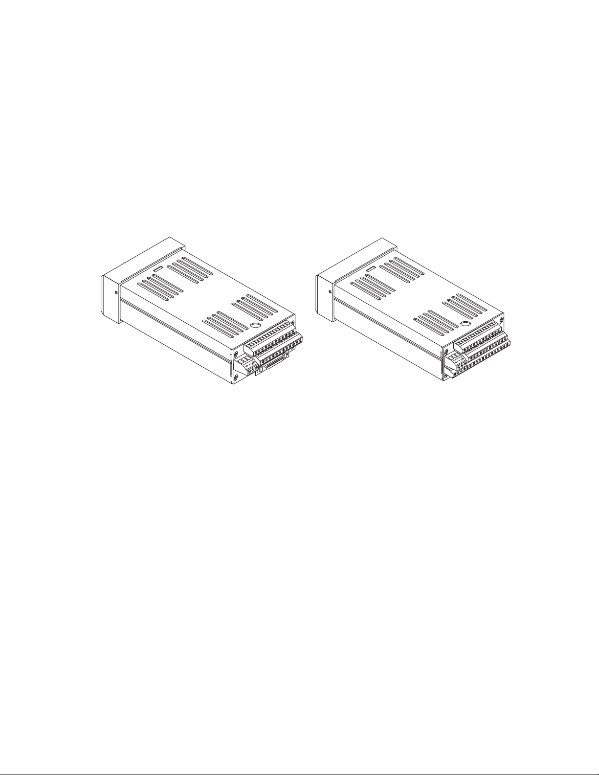
CLS200 Series
with SCSI Connector
CLS204 or CLS208
with TB18 Connector
Figure 1.3 CLS200 Rear Views
The CLS200 has the following features:
• Keypad and 2-line 16-character display.
• Screw terminals for the power and analog inputs and
communications.
• Input power is 12 to 24V
• A 50-pin SCSI cable connects the digital inputs and
outputs to the 50-terminal block (TB50). The CLS204
and CLS208 are available with an 18-terminal block
(TB18) in place of the SCSI connector, as shown in Fig-
ure 1.3.
The firmware resides in an EPROM. See Replacing the
EPROM on page 176 for information on removing and replacing the EPROM.
The operating parameters are stored in battery-backed
RAM. If there is a power loss the operating parameters are
unchanged. The battery has a ten-year shelf life, and it is
not used when the unit is on.
The microprocessor performs all calculations for input signal linearization, PID control, alarms and communications.
Î (dc) at 1 Amp.
Doc.# 0600-3050-2000 Watlow Anafaze 7
Page 24
Chapter 1: System Overview CLS200 Series User’s Guide
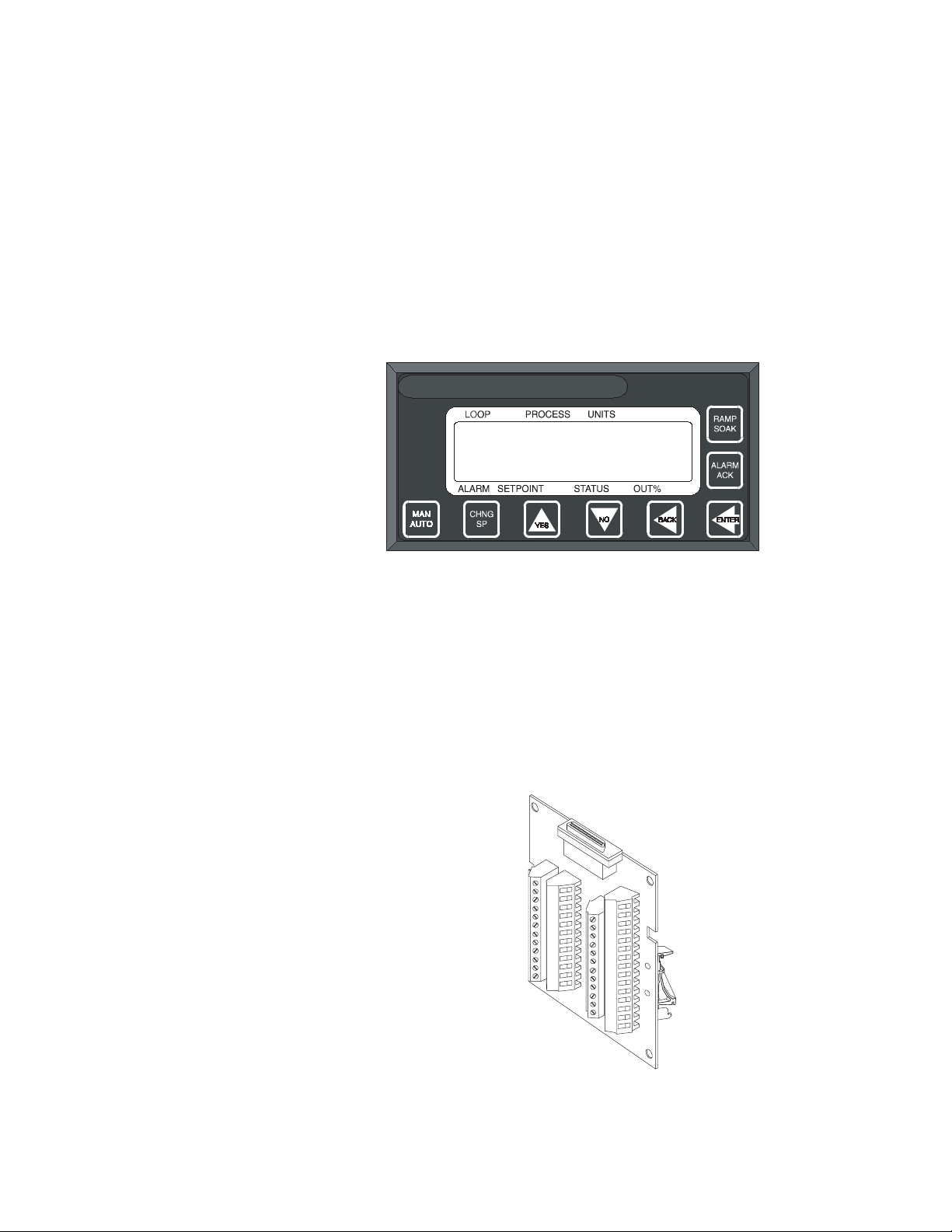
Front Panel Description
The display and touch keypad provide an intelligent way to
operate the controller. The display has 16 alphanumeric or
graphic characters per line. The 8-key keypad allows you to
change the operating parameters, controller functions, and
displays.
The information-packed displays show process variables,
setpoints, and output levels for each loop. A bar graph display, single loop display, scanning display and an alarm
display offer a real-time view of process conditions. Two access levels allow operator changes and supervisor changes.
WATLOW ANAFAZE CLS200
TB50
Figure 1.4 CLS200 Front Panel
The TB50 is a screw-terminal interface for control wiring
which allows you to connect relays, encoders and discrete I/
O devices to the CLS200. The screw terminal blocks accept
2
wires as large as 18 AWG (0.75 mm
connects the TB50 to the CLS200.
). A 50-pin SCSI cable
Figure 1.5 TB50
8 Watlow Anafaze Doc.# 0600-3050-2000
Page 25

CLS200 Series User’s Guide Chapter 1: System Overview
CLS200 Cabling
Watlow Anafaze provides cables required to install your
CLS200. A 50-pin SCSI cable connects the TB50 to the
CLS200.
The optional cable used to connect the CLS200 to a computer using EIA/TIA-232 communications has a DB9 or DB25
connector for the computer and bare wires for connecting to
the CLS200.
Safety
Watlow Anafaze has made every effort to ensure the reliability and safety of this product. In addition, we have provided recommendations that will allow you to safely install
and maintain this controller.
External Safety Devices
The CLS200 controller may fail full-on (100% output power) or full-off (0% output power), or may remain full-on if an
undetected sensor failure occurs. For more information
about failed sensor alarms, see Failed Sensor Alarms on
page 65.
Design your system to be safe even if the controller sends a
0% or 100% output power signal at any time. Install independent, external safety devices that will shut down the
system if a failure occurs.
Typically, a shutdown device consists of an FM-approved
high/low process limit controller that operates a shutdown
device such as an mechanical contactor. The limit controller monitors for a hazardous condition such as an undertemperature or over-temperature fault. If a hazardous condition is detected, the limit controller sends a signal to open
the contactor.
The safety shutdown device (limit controller and contactor)
must be independent from the process control equipment.
WARNING!
The controller may fail in a 0% or 100% power
output state. To prevent death, personal injury, equipment damage or property damage,
install external safety shutdown devices. If
must
death or injury may occur, you
install
FM-approved safety shutdown devices that
operate independently from the process control equipment.
With proper approval and installation, thermal fuses may
be used in some processes.
Doc.# 0600-3050-2000 Watlow Anafaze 9
Page 26

Chapter 1: System Overview CLS200 Series User’s Guide
Power-Fail Protection
In the occurrence of a sudden loss of power, this controller
can be programmed to reset the control outputs to off (this
is the default). Typically, when power is re-started, the controller restarts to data stored in memory. If you have programmed the controller to restart with control outputs on,
the memory-based restart might create an unsafe process
condition for some installations. Therefore, you should only
set the restart with outputs on if you are certain your system will safely restart. (See the Process Power Digital In-
put on page 79).
When using a computer or host device, you can program the
software to automatically reload desired operating constants or process values on power-up. Keep in mind that
these convenience features do not eliminate the need for independent safety devices.
Contact Watlow Anafaze immediately if you have any questions about system safety or system operation.
10 Watlow Anafaze Doc.# 0600-3050-2000
Page 27

2
Installation
This chapter describes how to install the CLS200 series
controller and its peripherals. Installation of the controller
involves the following procedures:
• Determining the best location for the controller
• Mounting the controller and TB50
• Power connection
• Input wiring
• Communications wiring (EIA/TIA-232 or EIA/TIA-
485)
• Output wiring
WARNING!
WARNING!
Doc.# 0600-3050-2000 Watlow Anafaze 11
Risk of electric shock. Shut off power to your
entire process before you begin installation
of the controller.
The controller may fail in a 0% or 100% power
output state. To prevent death, personal injury, equipment damage or property damage,
install external safety shutdown devices. If
failure may cause death or injury, you must
install FM-approved safety shutdown devices that operate independently from the process control equipment.
Page 28
Chapter 2: Installation CLS200 Series User’s Guide
Typical Installation
Figure 2.1 shows typical installations of the controller with
the TB50 and the TB18 terminal blocks. The type of terminal block you use greatly impacts the layout and wiring of
your installation site.
We recommend that you read this entire chapter first before beginning the installation procedure. This will help
you to carefully plan and assess the installation.
(See Figures 2.2 to 2.11.)
CLS200 with TB50
Signal Inputs
CLS200 with TB18
Signal Inputs
11 Digital Outputs (Control/Alarm)
2 Digital Inputs, 1 Digital/Pulse Input
SCSI Cable
CLS200
Power supply
CLS200
Power supply
Figure 2.1 CLS200 System Components
8 Digital Inputs,
35 Digital Outputs
(Control/Alarm)
Pulse Input
Mounting Controller Components
Install the controller in a location free from excessive heat
(more than 50º C [122° F]), dust, and unauthorized handling. Electromagnetic and radio frequency interference
can induce noise on sensor wiring. Select locations for the
CLS200 and TB50 such that wiring can be routed clear of
sources of interference such as high voltage wires, power
switching devices and motors.
NOTE!
12 Watlow Anafaze Doc.# 0600-3050-2000
For indoor use only.
Page 29

CLS200 Series User’s Guide Chapter 2: Installation
WARNING!
Recommended Tools
Mounting the Controller
To reduce the risk of fire or electric shock, install the CLS200 in a controlled environment,
relatively free of contaminants.
Use any of the following tools to cut a hole of the appropriate size in the panel.
• Jigsaw and metal file, for stainless steel and heavy-
weight panel doors.
• Greenlee 1/8-DIN rectangular punch (Greenlee part
number 600-68), for most panel materials and thicknesses.
• Nibbler and metal file, for aluminum and lightweight
panel doors.
You will also need these tools:
• Phillips head screwdriver
• 1/8 in. (3 mm) flathead screwdriver for wiring
• Multimeter
Mount the controller before you mount the terminal block
or do any wiring. The controller’s placement affects placement and wiring considerations for the other components
of your system.
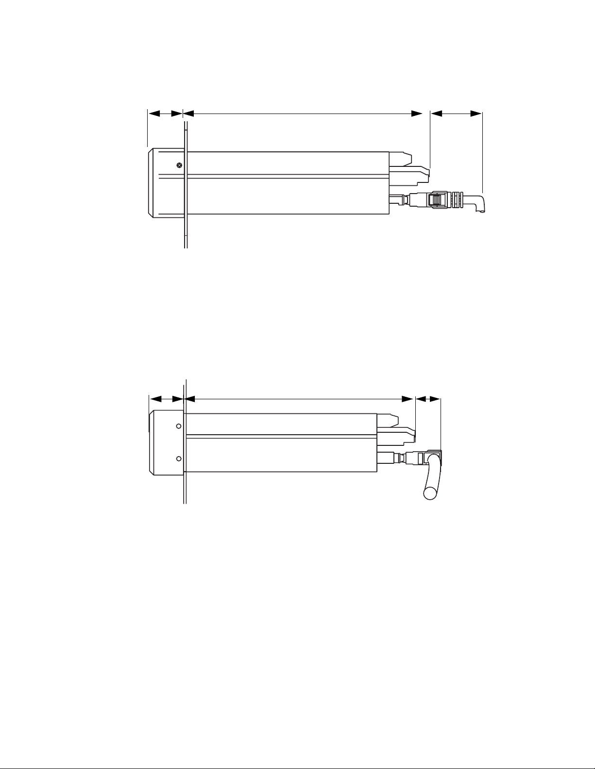
Ensure there is enough clearance for mounting brackets,
terminal blocks, and cable and wire connections; the controller extends up to 7.0 inches (178 mm) behind the panel
face and the screw brackets extend 0.5 inch (13 mm) above
and below it. If using a straight SCSI cable, allow for an additional 1.6 inches (41 mm) beyond the terminal block. If
using a right-angle SCSI cable, allow an additional 0.6 inch
(15 mm). (See Figure 2.2 and Figure 2.3.)
Doc.# 0600-3050-2000 Watlow Anafaze 13
Page 30
Chapter 2: Installation CLS200 Series User’s Guide
1.0 inch 7.0 inches 1.6 inch
(25 mm) (178 mm) (41 mm)
Figure 2.2 Clearance with Straight SCSI Cable
1.0 inch 7.0 inches 0.6 inch
(25 mm) (178 mm) (41 mm)
Figure 2.3 Clearance with Right-Angle SCSI
Cable
14 Watlow Anafaze Doc.# 0600-3050-2000
Page 31

CLS200 Series User’s Guide Chapter 2: Installation
Maximum Panel Thickness
0.2 inch (5 mm)
1.80 ± 0.020 inch
(45.7 ± 0.5 mm)
3.63 ± 0.020 inches
(92.2 ± 0.5 mm)
Figure 2.4 Wiring Clearances
We recommend you mount the controller in a panel not
more than 0.2 in. (5 mm) thick.
1. Choose a panel location free from excessive heat (more
than 50° C [122° F]), dust, and unauthorized handling.
(Make sure there is adequate clearance for the mounting hardware, terminal blocks, and cables. The controller extends 7.40 in. (178 mm) behind the panel.
Allow for an additional 0.60 to 1.60 in. (15 to 41 mm)
beyond the connectors.)
2. Temporarily cover any slots in the metal housing so
that dirt, metal filings, and pieces of wire do not enter
the housing and lodge in the electronics.
3. Cut a hole in the panel 1.80 in. (46 mm) by 3.63 in. (92
mm) as shown below. (This picture is NOT a template;
it is for illustration only.) Use caution; the dimensions
given here have 0.02 in. (1 mm) tolerances.
4. Remove the brackets and collar from the processor
module, if they are already in place.
5. Slide the processor module into the panel cutout.
6. Slide the mounting collar over the back of the proces-
sor module, making sure the mounting screw indentations face toward the back of the processor module.
Doc.# 0600-3050-2000 Watlow Anafaze 15
Page 32

Chapter 2: Installation CLS200 Series User’s Guide
Bracket (top and bottom)
25
23
21
19
17
15
13
11
9
7
5
3
1
+
26
24
22
20
18
16
14
12
10
8
6
4
2
Bezel
Panel
Mounting Collar
Figure 2.5 Mounting Bracket
7. Loosen the mounting bracket screws enough to allow
for the mounting collar and panel thickness. Place
each mounting bracket into the mounting slots (head
of the screw facing the back of the processor module).
Push each bracket backward then to the side to secure
it to the processor module case.
8. Make sure the case is seated properly. Tighten the installation screws firmly against the mounting collar to
secure the unit. Ensure that the end of the mounting
screws fit into the indentations on the mounting collar.
Mounting the TB50
There are two ways you can mount the TB50: Use the preinstalled DIN rail mounting brackets or use the plastic
standoffs. Follow the corresponding procedures to mount
the board.
TB50
Mounted
with Standoffs
TB50
Mounted to
DIN Rail
Figure 2.6 Mounting the TB50
16 Watlow Anafaze Doc.# 0600-3050-2000
Page 33

CLS200 Series User’s Guide Chapter 2: Installation
DIN Rail Mounting
Snap the TB50 on to the DIN rail by placing the hook side
on the rail first, then pushing the snap latch side in place.
(See Figure 2.7.)
Figure 2.7 TB50 Mounted on a DIN Rail (Front)
To remove the TB50 from the rail, use a flathead screwdriver to unsnap the bracket from the rail. (See Figure 2.8.)
Removal
catch for
screwdriver
DIN Rail
snap latch
Hook side
Figure 2.8 TB50 Mounted on DIN Rail (Side)
Doc.# 0600-3050-2000 Watlow Anafaze 17
Page 34

Chapter 2: Installation CLS200 Series User’s Guide
Mounting with Standoffs
1. Remove the DIN rail mounting brackets from the
TB50.
2. Select a location with enough clearance to remove the
TB50, its SCSI cable and the controller itself.
3. Mark the four mounting holes.
4. Drill and tap four mounting holes for #6 (3.5 mm)
screws or bolts.
5. Mount the TB50 with four screws.
There are four smaller holes on the terminal board. Use
these holes to secure wiring to the terminal block with tie
wraps.
0.7 in
0.2 in
(5 mm)
2.6 in
(66 mm)
(18 mm)
Figure 2.9 Mounting a TB50 with Standoffs
Mounting the Power Supply
If you use your own power supply for the CLS200, refer to
the power supply manufacturer’s instructions for mounting
information. Choose a Class 2 power supply that supplies
an isolated regulated 12 to 24V
3.4 in
(86 mm)
0.2 in
(5 mm)
4 holes for
#6 (3.5 mm)
screws or bolts
SCSI Connector
0.2 in
(5 mm)
3.6 in
(91 mm)
Î (dc) at 1 A.
18 Watlow Anafaze Doc.# 0600-3050-2000
Page 35

CLS200 Series User’s Guide Chapter 2: Installation
Mounting Environment
Leave enough clearance around the power supply so that it
can be removed.
Two holes for #10 (5.0 mm) screws or bolts
1.4 inch
(36 mm)
Mounting Steps
7.5 inches
(191 mm)
CAUTION!
0.3 inch
(8 mm)
0.7 inch
8.1 inches
(206 mm)
(18 mm)
Figure 2.10 CLS200 Power Supply Mounting
Bracket
Use 6-32, 1/4-inch screws only. Longer
screws may extend too far into the power
supply and short to components, damaging
the power supply.
1. Attach the bracket to the power supply using the
bracket’s two center holes.
2. Select a location with enough clearance to remove the
power supply and bracket. (See Figure 2.10.)
3. When a location has been determined for the power
supply, mark the bracket’s two outer holes for mounting.
4. Drill and tap the two mounting holes. (The bracket
holes accept up to #10 [5.0 mm] screws.)
5. Mount the power supply on the panel.
6. Tighten the screws.
Mounting the Dual DAC or Serial DAC Module
This section describes how to install the optional Dual DAC
and Serial DAC digital-to-analog converters.
Doc.# 0600-3050-2000 Watlow Anafaze 19
Page 36

Chapter 2: Installation CLS200 Series User’s Guide
Installation
Installation of the Dual DAC and Serial DAC is essentially
the same. The main differences are in the dimensions and
the wiring. Follow this procedure to correctly install these
devices.
Jumpers
The output signal range of the Dual DAC and Serial DAC
modules is configured with jumpers. See
Configuring Dual
DAC Outputs on page 186 and Configuring Serial DAC
Outputs on page 188 for information on setting these jump-
ers.
Mounting
1. Select a location. The unit is designed for wall mounting. Install it as close to the controller as possible.
2. Mark and drill four holes for screw mounting. Holes
accommodate #8 (4.0 mm) size screws. See Figure 2.11
for screw locations. Install the unit with the four
screws.
3.62 in
(91 mm)
Electrical
connections
Dual DAC
4 holes for #8 (4.0 mm)
screws or bolts
Electrical
connections
3.7 in
(94 mm)
4.40 in
(112 mm)
0.3 in
(8 mm)
3.00 in
(76 mm)
(17 mm)
1.75 in
(44 mm)
0.37 in
(9 mm)
0.65 in
3.62 in
(91 mm)
Electrical
connections
Serial DAC
4 holes for #8 (4.0 mm)
screws or bolts
Electrical
connections
4.7 in
(119 mm)
5.40 in
(137 mm)
0.3 in
(8 mm)
3.00 in
(76 mm)
0.37 in
(9 mm)
0.65 in
(17 mm)
1.75 in
(44 mm)
Figure 2.11 Dual DAC and Serial DAC
Dimensions
20 Watlow Anafaze Doc.# 0600-3050-2000
Page 37

CLS200 Series User’s Guide Chapter 2: Installation
System Wiring
Successful installation and operation of the control system
can depend on placement of the components and on selection of the proper cables, sensors, and peripheral components.
Routing and shielding of sensor wires and proper grounding of components can insure a robust control system. This
section includes wiring recommendations, instructions for
proper grounding and noise suppression, and considerations for avoiding ground loops.
WARNING!
CAUTION!
Wiring Recommendations
To reduce the risk of electrical shock, fire,
and equipment damage, follow all local and
national electrical codes. Correct wire sizes,
fuses and thermal breakers are essential for
safe operation of this equipment.
Do not wire bundles of low-voltage signal
and control circuits next to bundles of highvoltage ac wiring. High voltage may be inductively coupled onto the low-voltage circuits,
which may damage the controller or induce
noise and cause poor control.
Physically separate high-voltage circuits
from low-voltage circuits and from CLS200
hardware. If possible, install high-voltage ac
power circuits in a separate panel.
Follow these guidelines for selecting wires and cables:
• Use stranded wire. (Solid wire can be used for fixed
service; it makes intermittent connections when you
move it for maintenance.)
• Use 20 AWG (0.5 mm2) thermocouple extension wire.
Larger or smaller sizes may be difficult to install, may
break easily, or may cause intermittent connections.
• Use shielded wire. The electrical shield protects the
signals and the CLS200 from electrical noise. Connect
one end of the input and output wiring shield to earth
ground.
• Use copper wire for all connections other than thermocouple sensor inputs.
Doc.# 0600-3050-2000 Watlow Anafaze 21
Page 38

Chapter 2: Installation CLS200 Series User’s Guide
Table 2.1 Cable Recommendations
Function Mfr. P/N
Analog Inputs
RTD Inputs
Thermocouple Inputs T/C Ext. Wire 2 20 0.5
Control Outputs and
Digital I/O
Analog Outputs
Computer Communication: EIA/TIA-232, 422
or 485, or 20 mA
Belden 9154
Belden 8451
Belden 8772
Belden 9770
Belden 9539
Belden 9542
Ribbon Cable
Belden 9154
Belden 8451
Belden 9729
Belden 9730
Belden 9842
Belden 9843
Belden 9184
No. of
Wires
2
2
3
3
9
20
50
2
2
4
6
4
6
4
AWG
20
22
20
22
24
24
22 to 14
20
22
24
24
24
24
22
mm
0.5
0.5
0.5
0.5
0.2
0.2
0.5 to 2.5
0.5
0.5
0.2
0.2
0.2
0.2
0.5
2
4,000 ft. (1,219 m)
4,000 ft. (1,219 m)
6,000 ft. (1,829 m)
Maximum
Length
Noise Suppression
Symptoms of RFI/EMI
The CLS200’s outputs are typically used to drive solid state
relays. These relays may in turn operate more inductive
types of loads such as electromechanical relays, alarm
horns and motor starters. Such devices may generate electromagnetic interference (EMI or noise). If the controller is
placed close to sources of EMI, it may not function correctly. Below are some tips on how to recognize and avoid problems with EMI.
For earth ground wire, use a large gauge and keep the
length as short as possible. Additional shielding may be
achieved by connecting a chassis ground strap from the
panel to CLS200 case.
If your controller displays the following symptoms, suspect
EMI:
• The controller’s display blanks out and then reenergizes as if power had been turned off for a moment.
• The process variable does not display correctly.
EMI may also damage the digital output circuit—so digital
outputs will not turn on. If the digital output circuit is damaged, return the controller to Watlow Anafaze for repair.
22 Watlow Anafaze Doc.# 0600-3050-2000
Page 39

CLS200 Series User’s Guide Chapter 2: Installation
Avoiding RFI/EMI
• To avoid or eliminate most RFI/EMI noise problems:
• Connect the CLS200 case to earth ground. The
CLS200 system includes noise suppression circuitry.
This circuitry requires proper grounding.
• Separate the 120 or 240V
low-level input and output leads connected to the
CLS200 series controller. Do not run the digital I/O or
control output leads in bundles with ac wires.
• Where possible, use solid-state relays (SSRs) instead
of electromechanical relays. If you must use electromechanical relays, try to avoid mounting them in the
same panel as the CLS200 series equipment.
• If you must use electromechanical relays and you
must place them in a panel with CLS200 series equipment, use a 0.01 microfarad capacitor rated at
1000VÅ (ac) (or higher) in series with a 47 Ω, 0.5 watt
resistor across the N.O. contacts of the relay load. This
is known as a snubber network and can reduce the
amount of electrical noise.
• You can use other voltage suppression devices, but
they are not usually required. For instance, you can
place a metal oxide varistor (MOV) rated at 130VÅ for
120VÅ (ac) control circuits across the load, which limits the peak ac voltage to about 180VÅ (ac) (Watlow
Anafaze part number 26-130210-00). You can also
place a transorb (back-to-back zener diodes) across the
digital output, which limits the digital output voltage.
Å (ac) power leads from the
Additional Recommendations for a Noise Immune System
It is strongly recommended that you:
• Isolate outputs through solid-state relays, where possible.
• Isolate RTDs or “bridge” type inputs from ground.
• Isolate digital inputs from ground through solid state
relays. If this is not possible, then make sure the digital input is the only connection to earth ground other
than the chassis ground.
• If you are using EIA/TIA-232 from a non-isolated host,
either (1) do not connect any other power common
point to earth ground, or (2) use an optical isolator in
the communications line.
Doc.# 0600-3050-2000 Watlow Anafaze 23
Page 40

Chapter 2: Installation CLS200 Series User’s Guide
Ground Loops
Ground loops occur when current passes from the process
through the controller to ground. This can cause instrument errors or malfunctions.
A ground loop may follow one of these paths, among others:
• From one sensor to another.
• From a sensor to the communications port.
• From a sensor to the dc power supply.
The best way to avoid ground loops is to minimize unneces-
sary connections to ground. Do not connect any of the following terminals to each other or to earth ground:
• Power supply dc common
• TB1, terminals 5, 6, 11, 12 (analog common)
• TB1, terminal 17 (reference voltage common)
• TB1, terminals 23, 24 (communications common)
• TB2, terminal 2 (dc power common)
Special Precautions for the CLS216
The CLS216 has single-ended inputs. All the negative sensor leads are tied to the analog common. That means there
is no sensor-to-sensor isolation. Proper grounding is critical
for this unit. Take these additional precautions with a
CLS216:
• Use all ungrounded or all well-grounded thermocouples, not a mix.
• If using a mixture of thermocouples or low-voltage inputs (<500 mV) and current inputs, connect the negative leads of the current transmitters to terminal 17
(Ref Com) on TB1.
• If using voltage transmitters, use only sourcing models or configuration. Sinking configurations will not
work.
• Isolate the controller’s communication port (if used) by
using an optically isolated 232-to-485 converter.
Personal Computers and Ground Loops
Many PC communications ports connect the communications common to chassis ground. When such a PC is connected to the controller, this can provide a path to ground
for current from the process that can enter the controller
through a sensor (such as a thermocouple). This creates a
ground loop that can affect communications and other controller functions. To eliminate a ground loop, either use an
optically isolated communications adapter or take measures to ensure that sensors and all other connections to
the controller are isolated and not conducting current into
the unit.
24 Watlow Anafaze Doc.# 0600-3050-2000
Page 41

CLS200 Series User’s Guide Chapter 2: Installation
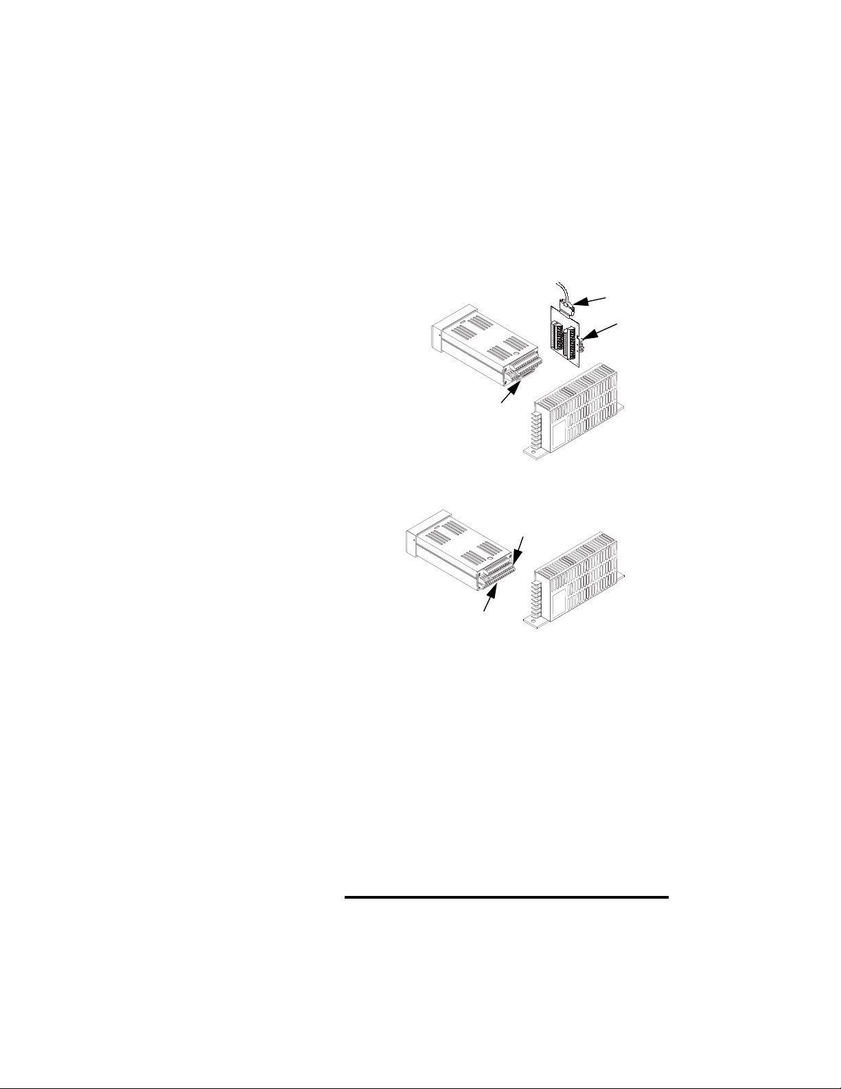
Power Connections
This section covers making the power connections to the
CLS200 and connecting the TB50.
TB1
(to signal
TB2
(to power
supply)
Figure 2.12 CLS200 Series Controller with
TB18
inputs
TB18
(to digital
outputs)
TB2
(to power
supply)
Wiring the Power Supply
WARNING!
TB1
(to signal
inputs
SCSI-2
(to TB50)
Figure 2.13 CLS200 Series Controller with
TB50
Use a power supply with a Class 2 rating
only. UL approval requires a Class 2 power
supply.
Connect power to the controller before any other connections, This allows you to ensure that the controller is working before any time is taken installing inputs and outputs.
Doc.# 0600-3050-2000 Watlow Anafaze 25
Page 42

Chapter 2: Installation CLS200 Series User’s Guide
Table 2.2 Power Connections
Function Power Supply CLS200 TB2
NOTE!
DC Power
(Controller)
DC Common
Earth Ground Ground
1. Connect the dc common terminal on the power supply
to the dc common (-) terminal on CLS200 TB2.
2. Connect the positive terminal on the power supply to
the dc positive (+) terminal on CLS200 TB2.
3. If using an isolated dc output or another power supply
to power the loads, connect the dc common of the supply powering the loads to the dc common of the supply
powering the controller.
4. Use the ground connector on TB2 for chassis ground.
This terminal is connected to the CLS200 chassis and
must be connected to earth ground.
5. Connect 120/240V
+12 to 24V
12 to 24VÎ (dc)
Å (ac) power to the power supply.
Î (dc)
Common
+
-
Connect the dc common of the power supply
used for loads to the dc common of the supply powering the controller. If the supplies
are not referenced to one another, the controller’s outputs will not be able to switch the
loads.
NOTE!
When making screw terminal connections,
tighten to 4.5 to 5.4 inch-pound (0.5 to 0.6
Nm).
CAUTION!
Without proper grounding, the CLS200 may
not operate properly or may be damaged.
26 Watlow Anafaze Doc.# 0600-3050-2000
Page 43

CLS200 Series User’s Guide Chapter 2: Installation
CAUTION!
NOTE!
To prevent damage from incorrect connections, do not turn on the ac power before testing the connections as explained in Testing
Your System on page 28.
Do not connect the controller’s dc common
(COM) to earth ground . Doing so will de-
feat the noise protection circuitry, making
measurements less stable.
Power Supply
+V1 (5V)
0 (5V COM)
+V2 (+15V)
COM (15V COM)
-V2 (-15V)
Add jumper *
SSR
SSR
G
C
N
OMV
D
+
CLS200
**
SSR
SSR
ACN (AC Neutral)
120/240
Vı (ac)
Supply
* If using 5VÎ (dc) for outputs, jumper 5V common to 15V common.
** Connect terminals to ac panel ground.
Connecting TB50 to CLS200
(Ground)
ACL (AC Line)
white
N
black
H
green
G
**
1 2 3 4
+
5
Serial DAC
C
O
M
Figure 2.14 Power Connections with the
CLS200 Power Supply
1. Connect the SCSI cable to the controller.
2. Connect the SCSI cable to the TB50.
Doc.# 0600-3050-2000 Watlow Anafaze 27
Page 44

Chapter 2: Installation CLS200 Series User’s Guide
Testing Your System
This section explains how to test the controller after installation and prior to making field wiring connections.
TB50 or TB18 Test
Use this procedure to verify that the TB50 or TB18 is properly connected and supplied with power:
1. Turn on power to the CLS200. The display should read
CALCULATING CHECKSUM then show the bar graph
display. (See Figure 3.3.) If you do not see these dis-
plays, disconnect power and check wiring and power
supply output.
Digital Output Test
2. Measure the +5V
a) Connect the voltmeter’s common lead to TB50 or
TB18 terminal 3 or TB18 terminal 2.
b) Connect the voltmeter’s positive lead to TB50 or
TB18 screw terminal 1. The voltage should be
+4.75 to +5.25VÎ (dc).
Use this procedure to test the controller’s outputs before
loads are connected. If using it at another time for troubleshooting, disconnect loads from outputs before testing.
1. Connect a 500 Ω to 100 kΩ resistor between TB50 or
TB18 screw terminal 1 and a digital output terminal.
(See Table 2.5, TB18 Connections on page 40; Table
2.6, TB50 Connections for CLS204 and CLS208 on
page 41; or Table 2.7, TB50 Connections for CLS216 on
page 42.)
2. Connect the voltmeter’s positive lead to screw terminal 1.
3. Connect the common lead to the digital output terminal.
4. Use the digital output test in the MANUAL I/O TEST
menu to turn the digital output on and off.
Digital Output on page 104 and Digital Output Number on page 104.) When the output is ON, the output
voltage should be less than 1V. When the output is
OFF, the output voltage should be between 4.75 and
5.25V.
Î (dc) supply at the TB50 or TB18:
(See Test
NOTE!
By default, heat outputs are enabled. Only
disabled outputs may be turned on using the
manual I/O test. To test heat outputs, set the
corresponding loop to manual mode 100%
output. See Selecting the Control Status on
page 61.
28 Watlow Anafaze Doc.# 0600-3050-2000
Page 45

CLS200 Series User’s Guide Chapter 2: Installation
Digital Input Test
Use the following procedure to test digital inputs before
connecting to field devices:
1. Disconnect any system wiring from the input to be
tested.
2. Go to the DIGITAL INPUTS test in the MANUAL I/O
TEST menu. (See Digital Inputs on page 103.) This test
shows whether the digital inputs are H (high, or open)
or L (low, or closed).
3. Attach a wire to the terminal of the digital input you
want to test. See tables 2.5 to 2.7 on pages 40 to 42 for
connections.
a) When the wire is connected only to the digital in-
put terminal, the digital input test should show
that the input is H (high, or open).
b) When you connect the other end of the wire to the
controller common (TB50 terminal 3 or TB18 terminal 2), the digital input test should show that
the input is L (low, or closed).
Sensor Wiring
CAUTION!
This section describes how to properly connect thermocouples, RTDs, current and voltage inputs to your controller.
The controller can accept any mix of available input types.
Some input types require that special scaling resistors be
installed (generally done by Watlow Anafaze before the
controller is delivered).
All inputs are installed at the CH input connectors (TB1) at
the back of the controller. The illustrations below show the
connector locations for all the CLS200 series controllers.
Never run input leads in bundles with high
power wires or near other sources of EMI.
This could inductively couple voltage onto
the input leads and damage the controller, or
could induce noise and cause poor measurement and control.
Doc.# 0600-3050-2000 Watlow Anafaze 29
Page 46

Chapter 2: Installation CLS200 Series User’s Guide
Figure 2.15 CLS200 Connector Locations
Input Wiring Recommendations
Use multicolored stranded shielded cable for analog inputs.
Watlow Anafaze recommends that you use 20 AWG wire
(0.5 mm
also use 24 or 22 AWG wiring (0.2 mm
shielded twisted pair; some require a 3-wire input.
Follow the instructions pertaining to the type(s) of input(s)
you are installing.
The controller accepts the following inputs without any
special scaling resistors:
• J, K, T, S, R, B and E thermocouples.
• Linear inputs with ranges between -10 and 60 mV.
Any unused inputs should be set to SKIP or jumpered to
avoid thermocouple break alarms.
2
). If the sensor manufacturer requires it, you can
2
). Most inputs use a
30 Watlow Anafaze Doc.# 0600-3050-2000
Page 47

CLS200 Series User’s Guide Chapter 2: Installation
Thermocouple Connections
Connect the positive lead of any of the supported thermocouple types to the IN+ terminal for one of the loops and the
negative lead to the corresponding IN- terminal.
2
Use 18 or 20 AWG (0.5 or 0.75 mm
ple inputs. Most thermocouple wire is solid, unshielded
wire. When using shielded wire, ground one end only.
) for all the thermocou-
NOTE!
CH IN+
*CH IN-
*For CLS216 use Com
White
Red
Shield (if present)
Earth Ground
at Process End
Type J
thermocouple
Figure 2.16 Thermocouple Connections
When mixing current inputs with low-voltage
inputs (thermocouples or voltage inputs <1V)
to a CLS216, connect the current signal to the
IN+ and Ref Com terminals. If no low-voltage
sensors are used, connect current inputs to
the IN+ and Com terminals on TB1. For all inputs to a CLS204 or CLS208, connect the
sensors to the IN+ and Com terminals.
CAUTION!
Ground loops and common mode noise can
damage the controller or disrupt measurements. To minimize ground loops and common mode noise:
• With a CLS216, use only ungrounded ther-
mocouples with each thermocouple sheath
electrically connected to earth ground. The
negative sensor terminals on the CLS216 are
tied to analog common.
• With a CLS204 or CLS208, do not mix
grounded and ungrounded thermocouples. If
any thermocouple connected to the controller is of grounded construction, all thermocouples should be of grounded construction
Doc.# 0600-3050-2000 Watlow Anafaze 31
Page 48

Chapter 2: Installation CLS200 Series User’s Guide
and each should be connected to ground at
the process end.
• Connect the earth ground terminal on TB2
to a good earth ground, but do not connect
the analog common to earth ground. The
CLS200 uses a floating analog common for
sensor measurements. The noise protection
circuits on the sensor inputs function correctly only when the controller is correctly installed. See Ground Loops on page 24.
RTD Input Connections
This input type requires scaling resistors. Watlow Anafaze
recommends that you use a 100 Ω, 3-wire platinum RTD to
prevent reading errors due to cable resistance. If you use a
2-wire RTD, jumper the negative input to common. If you
must use a 4-wire RTD, leave the fourth wire unconnected.
Figure 2.17 RTD Connections to CLS204 or
Reference Voltage Terminals
The +5V Ref and Ref Com terminals are provided in order
to power external bridge circuits for special sensors. Do not
connect any other types of devices to these terminals.
Voltage Input Connections
This input type requires scaling resistors. Special input resistors installed at Watlow Anafaze divide analog input
voltages such that the controller sees a -10 to 60 mV signal
on the loop.
CH
CH
IN +
100 Ω RTD
IN -
Com
CLS208
32 Watlow Anafaze Doc.# 0600-3050-2000
Page 49

CLS200 Series User’s Guide Chapter 2: Installation
CLS204 and CLS208
Current Input Connections
CH IN+
CH IN-
CLS216
CH IN+
Com
Device with
Voltage
Output
Device with
Voltage
Output
Figure 2.18 Linear Voltage Signal Connections
This input type requires scaling resistors. Special input resistors installed at Watlow Anafaze for analog current signals are such that the controller sees a -10 to 60 mV signal
across its inputs for the loop.
CLS204 and CLS208
CH IN+
CH IN-
Device with
Current
Output
CLS216
CH IN+
Com/Ref Com
Device with
Current
Output
Figure 2.19 Linear Current Signal Connections
NOTE!
Doc.# 0600-3050-2000 Watlow Anafaze 33
When mixing current inputs with low-voltage
inputs (thermocouples or voltage inputs <1V)
to a CLS216, connect the current signal to the
IN+ and Ref Com terminals. When no lowvoltage sensors are used, connect current inputs to the IN+ and Com terminals on TB1.
For all inputs to a CLS204 or CLS208, connect the sensors to the IN+ and Com terminals.
Page 50

Chapter 2: Installation CLS200 Series User’s Guide
Pulse Input Connections
The CLS200 can accept a pulse input of up to 2000 Hz from
a device such as an encoder. The frequency of this input is
scaled with user-set parameters. See Setup Loop Input
Menu on page 82 and Chapter 9, Linear Scaling Examples.
This scaled value is the process variable for loop 5 on a
CLS204, loop 9 on a CLS208, or loop 17 on a CLS216.
The CLS200 can accommodate encoder signals up to 24V
(dc) using a voltage divider or can power encoders with the
5VÎ (dc) from the TB50 or TB18. The following figures illustrate connecting encoders. A pull-up resistor in the
CLS200 allows open collector inputs to be used.
Î
NOTE!
If the signal on the pulse input exceeds
10kHz the controller’s operation may be disrupted. Do not connect the pulse input to a
signal source that may exceed 10kHz.
CLS200 and TB50 or TB18
+5VÎ (dc)
10 kΩ
Figure 2.20 Encoder with 5V
CLS200 and TB50 or TB18
+5VÎ (dc)
10 kΩ
Pulse Input
Com
Pulse Input
Com
R2
Encoder
ÎÎ
ÎÎ
(dc) TTL Signal
R1
Encoder
Figure 2.21 Encoder Input with Voltage Divider
For encoders with signals greater than 5VÎ (dc), use a voltage divider to drop the voltage to 5 volts at the input. Use
appropriate values for R
excitation voltage. Be sure not to exceed the specific current load on the encoder.
34 Watlow Anafaze Doc.# 0600-3050-2000
and R2 depending on the encoder
1
Page 51

CLS200 Series User’s Guide Chapter 2: Installation
Wiring Control and Digital I/O
This section describes how to wire and configure the control
outputs for the CLS200 series controller.
NOTE!
Control outputs are connected to the
CLS200’s common when the control output
is on (low). Be careful when you connect external devices that may have a low side at a
voltage other than controller ground, since
you may create ground loops.
If you expect grounding problems, use isolated solid state relays and isolate the control
device inputs.
The CLS200 provides dual PID control outputs for each
loop. These outputs can be enabled or disabled, and are
connected via TB50 or TB18.
Output Wiring Recommendations
When wiring output devices, use multicolored, stranded,
shielded cable for analog outputs and digital outputs connected to panel-mounted solid state relays.
• Analog outputs usually use a twisted pair.
• Digital outputs usually have 9 to 20 conductors, depending on wiring technique.
Cable Tie Wraps
Once you have wired outputs to the TB50, install the cable
tie wraps to reduce strain on the connectors.
Each row of terminals has a cable tie wrap hole at one end.
Thread the cable tie wrap through the cable tie wrap hole.
Then wrap the cable tie wrap around the wires attached to
that terminal block.
Digital Outputs
The CLS200 series provides dual control outputs for up to
16 loops. The controller’s default configuration has all heat
outputs enabled and all cool outputs disabled. Disabling a
heat output makes that output available to be used as a
control or an alarm output. See Enable or Disable Heat or
Cool Outputs on page 94. The CPU watchdog timer output
can be used to monitor the state of the controller with an
external circuit or device. See CPU Watchdog Timer on
page 38.
Doc.# 0600-3050-2000 Watlow Anafaze 35
Page 52

Chapter 2: Installation CLS200 Series User’s Guide
Table 2.3 Digital Output States and Values
Stored in the Controller
State Value Description
Off High Open circuit
On Low Sinking current to common
The digital outputs sink current from the load to the controller common. The load may powered by the 5V
supplied by the controller at the TB50. Alternately, an external power supply may be used to drive loads.
Keep in mind the following points when using an external
power supply:
• The CLS200 power supply available from Watlow
Anafaze includes a 5VÎ (dc) supply. When using it to
supply output loads, connect the 5VÎ (dc) common to
the 15VÎ (dc) common at the power supply.
• Do not exceed +24 volts.
• If you tie the external load to earth ground, or if you
cannot connect it as shown in (See Figure 2.22), then
use a solid-state relay.
All digital outputs are sink outputs referenced to the
CLS200 series controller common supply. These outputs
are low (pulled to common) when they are on.
The outputs conduct current when they are low or on. The
maximum current sink capability is 60 mA at 24VÎ (dc).
They cannot “source” current to a load.
Î (dc)
TB50 or TB18
External
+5V
Î (dc)
Digital Output 1
Digital Output 2
Using Internal Power Supply
Using External Power Supply
Loads
Power
Supply
to earth ground or
equipment ground
TB50 or TB18
Control Common
Digital Output 1
Digital Output 2
+
-
Do not connect
Loads
Figure 2.22 Digital Output Wiring
36 Watlow Anafaze Doc.# 0600-3050-2000
Page 53

CLS200 Series User’s Guide Chapter 2: Installation
Configuring Outputs
Keep in mind the following points as you choose outputs for
control and alarms:
• You can enable or disable the control outputs. The default setting is heat outputs enabled, cool outputs disabled.
• You can program each control output individually for
on/off, time proportioning, distributed zero crossing, or
Serial DAC control.
• You can individually program each control output for
direct or reverse action.
• Alarm outputs other than the global alarm are nonlatching.
• Alarms can be suppressed during process start up and
for preprogrammed durations. See Alarm Delay on
page 103.
• Alarm outputs can be configured as a group as normally on (low) or normally off (high). See Digital Output
Polarity on Alarm on page 81.
Control and Alarm Output Connections
Typically control and alarm outputs use external optically
isolated solid state relays (SSRs). SSRs accept a 3 to 32V
(dc) input for control, and some can switch up to 100 Amps
at 480 VÅ (ac). For larger currents, use silicon control rectifier (SCR) power controllers up to 1000 Amps at 120 to
600VÅ (ac). You can also use SCRs and a Serial DAC for
phase-angle fired control.
The 34 control and alarm outputs are open collector outputs referenced to the CLS200’s common. Each output
sinks up to 60 mAÎ (dc) to the controller common when on.
NOTE!
Control outputs are SINK outputs. They are
Low when the output is ON. Connect them to
the negative side of solid state relays.
Figure 2.23 shows sample heat, cool and alarm output connections.
TB50 or TB18
Heat Output
Cool Output
Alarm Output
+5VÎ (dc)
SSR SSR SSR
+-
+-
Î
+-
Figure 2.23 Sample Heat, Cool and Alarm
Output Connections
Doc.# 0600-3050-2000 Watlow Anafaze 37
Page 54

Chapter 2: Installation CLS200 Series User’s Guide
CPU Watchdog Timer
TB50 or TB18
Heat Output
Cool Output
Alarm Output
Common
SSR
+-
- PS +
SSR
SSR
+-
Figure 2.24 Output Connections Using
External Power Supply
The CPU watchdog timer constantly monitors the microprocessor. It is a sink output located on TB50 terminal 6 or
TB18 terminal 3. The output can be connected to an external circuit or device in order to determine if the controller
is powered and operational. Do not exceed 5V
mAÎ (dc) rating for the watchdog output. The output is low
(on) when the microprocessor is operating; when it stops
operating, the output goes high (off).
Figure 2.25 and Figure 2.26 show the recommended circuit
for the watchdog timer output for the TB50 and the TB18.
Î (dc), 10
+-
Digital Inputs
TB50
+ 5VÎ (dc)
(Terminal 1)
Watchdog Timer
(Terminal 6)
+
SSR
-
Figure 2.25 TB50 Watchdog Timer Output
TB18
+ 5VÎ (dc)
(Terminal 1)
Watchdog Timer
(Terminal 3)
+
SSR
-
Figure 2.26 TB18 Watchdog Timer Output
All digital inputs are transistor-transistor logic (TTL) level
inputs referenced to control common and the internal +5V
power supply of the CLS200.
When an input is connected to the controller common, the
input is considered on. Otherwise, the input is considered
38 Watlow Anafaze Doc.# 0600-3050-2000
Page 55

CLS200 Series User’s Guide Chapter 2: Installation
off. Most features that use the digital inputs can be userconfigured to activate when an input is either on or off.
In the off state, internal 10 k resistors pull the digital inputs high to 5V
mon.
Î (dc) with respect to the controller com-
Table 2.4 Digital Inputs States and Values
Stored in the Controller
State Value Description
Off High Open circuit
External Switching Devices
To ensure that the inputs are reliably switched, use a
switching device with the appropriate impedances in the on
and off states and do not connect the inputs to external
power sources.
When off, the swiching device must provide an impedance
of at least 11 kΩ to ensure that the voltage will rise to
greater than 3.7V
not more than 1 kΩ impedance to ensure the voltage drops
below 1.3VÎ (dc).
To install a switch as a digital input, connect one lead to the
common terminal on the TB50 (terminals 3 and 4) or TB18
(terminal 2). Connect the other lead to the desired digital
input terminal on the TB50 (terminals 43 to 50) or TB18
(terminals 16 to 18).
Functions Activated by Digital Inputs
Use digital inputs to activate the following functions:
• Load a job that is stored in controller memory. See Job
Select Digital Inputs on page 76.
• Change all loops to manual mode at specified output
levels. See Output Override Digital Input on page 77.
• Enable thermocouple short detection. See Process
Power Digital Input on page 79.
• Restore control automatically after a failed sensor has
been repaired. See Restore PID Digital Input on page 92.
On Low
Digital Input connected to
controller common
Î (dc). When on, the switch must provide
TB50
Input
Control Com
External
Switching
Device
Figure 2.27 Wiring Digital Inputs
Doc.# 0600-3050-2000 Watlow Anafaze 39
Page 56

Chapter 2: Installation CLS200 Series User’s Guide
TB18 Connections (CLS204 and CLS208 Only)
Table 2.5 TB18 Connections
Control Output
1
Terminal Function CLS204 CLS208
1
+5V
Î (dc)
2 CTRL COM
3 Watchdog timer
4 Global alarm
5 Output 1 Loop 1 heat Loop 1 heat
6 Output 2 Loop 2 heat Loop 2 heat
7 Output 3 Loop 3 heat Loop 3 heat
8 Output 4 Loop 4 heat Loop 4 heat
9 Output 5 Pulse loop heat Loop 5 heat
10 Output 6 Loop 1 cool Loop 6 heat
11 Output 7 Loop 2 cool Loop 7 heat
12 Output 8 Loop 3 cool Loop 8 heat
13 Output 9 Loop 4 cool Pulse loop heat
14 Output 10 Pulse loop cool Loop 1 cool
15
Output 34
2
Serial DAC clock Serial DAC clock
16 Input 1
17 Input 2
18 Input 3/Pulse input
1
The indicated outputs are dedicated for control when enabled in
the loop setup. If one or both of a loop’s outputs are disabled, the
corresponding digital outputs become available for alarms or
ramp/soak events.
2
If you install a Watlow Anafaze Serial DAC, the CLS200 series
controller uses digital output 34 for a clock line. You cannot use
output 34 for anything else when you have a Serial DAC installed.
40 Watlow Anafaze Doc.# 0600-3050-2000
Page 57

CLS200 Series User’s Guide Chapter 2: Installation
TB50 Connections
Table 2.6 TB50 Connections for CLS204 and
CLS208
Control Output
Ter-
minal
1
3 CTRL COM 4 CTRL COM
5 Not Used 6 Watchdog
7 Pulse Input 8 Global Alarm
9 Output 1 Loop 1 heat Loop 1 heat 10
11 Output 2 Loop 2 heat Loop 2 heat 12 Output 33
13 Output 3 Loop 3 heat Loop 3 heat 14 Output 32
15 Output 4 Loop 4 heat Loop 4 heat 16 Output 31
17 Output 5 Loop 5 heat Pulse loop heat 18 Output 30
19 Output 6 Loop 6 heat Loop 1 cool 20 Output 29
21 Output 7 Loop 7 heat Loop 2 cool 22 Output 28
23 Output 8 Loop 8 heat Loop 3 cool 24 Output 27
25 Output 9 Pulse loop
27 Output 10 Loop 1 cool Pulse loop cool 28 Output 25
29 Output 11 Loop 2 cool 30 Output 24
31 Output 12 Loop 3 cool 32 Output 23
33 Output 13 Loop 4 cool 34 Output 22
35 Output 14 Loop 5 cool 36 Output 21
37 Output 15 Loop 6 cool 38 Output 20
39 Output 16 Loop 7 cool 40 Output 19
41 Output 17 Loop 8 cool 42 Output 18 Pulse
43 Input 1 44 Input 2
45 Input 3 46 Input 4
47 Input 5 48 Input 6
49 Input 7 50 Input 8
Function CLS208 CLS204
+5V
Î (dc)
Loop 4 cool 26 Output 26
heat
1
Ter-
minal
2
Function CLS208 CLS204
+5VÎ (dc)
Timer
Output 34
2
loop cool
Control Output
1
1
The indicated outputs are dedicated for control when enabled in
the loop setup. If one or both of a loop’s outputs are disabled, the
corresponding digital outputs become available for alarms or
ramp/soak events.
2
If you install a Watlow Anafaze Serial DAC, the controller uses
digital output 34 (terminal 10) for a clock line. You cannot use output 34 for anything else when you have a Serial DAC installed.
Doc.# 0600-3050-2000 Watlow Anafaze 41
Page 58

Chapter 2: Installation CLS200 Series User’s Guide
Table 2.7 TB50 Connections for CLS216
Terminal Function
Î (dc)
1
3
5
7
9
11
13
15
17
19
21
23
25
27
29
31
33
35
37
39
41
43
45
47
49
+5V
CTRL COM 4 CTRL COM
Not Used 6 Watchdog Timer
Pulse Input 8 Global Alarm
Output 1 Loop 1 heat 10
Output 2 Loop 2 heat 12 Output 33 Loop 16 cool
Output 3 Loop 3 heat 14 Output 32 Loop 15 cool
Output 4 Loop 4 heat 16 Output 31 Loop 14 cool
Output 5 Loop 5 heat 18 Output 30 Loop 13 cool
Output 6 Loop 6 heat 20 Output 29 Loop 12 cool
Output 7 Loop 7 heat 22 Output 28 Loop 11 cool
Output 8 Loop 8 heat 24 Output 27 Loop 10 cool
Output 9 Loop 9 heat 26 Output 26 Loop 9 cool
Output 10 Loop 10 heat 28 Output 25 Loop 8 cool
Output 11 Loop 11 heat 30 Output 24 Loop 7 cool
Output 12 Loop 12 heat 32 Output 23 Loop 6 cool
Output 13 Loop 13 heat 34 Output 22 Loop 5 cool
Output 14 Loop 14 heat 36 Output 21 Loop 4 cool
Output 15 Loop 15 heat 38 Output 20 Loop 3 cool
Output 16 Loop 16 heat 40 Output 19 Loop 2 cool
Output 17 Pulse loop heat 42 Output 18 Loop 1 cool
Input 1 44 Input 2
Input 3 46 Input 4
Input 5 48 Input 6
Input 7 50 Input 8
CLS216
Control Output
Terminal Function
1
2
+5VÎ (dc)
Output 34
CLS216
Control Output
2
Pulse loop cool
1
1
The indicated outputs are dedicated for control when enabled in
the loop setup. If one or both of a loop’s outputs are disabled, the
corresponding digital outputs become available for alarms or
ramp/soak events.
2
If you install a Watlow Anafaze Serial DAC, the controller uses
digital output 34 (terminal 10) for a clock line. You cannot use output 34 for anything else when you have a Serial DAC installed.
42 Watlow Anafaze Doc.# 0600-3050-2000
Page 59

CLS200 Series User’s Guide Chapter 2: Installation
Analog Outputs
Analog outputs can be provided by using a Dual DAC or Serial DAC module to convert the open collector outputs from
the controller. Use multicolored stranded shielded cable for
analog outputs. Analog outputs generally use a twisted
pair wiring. The following sections describe how to connect
the Dual DAC and Serial DAC modules to power the controller outputs and the load.
Wiring the Dual DAC
A Dual DAC module includes two identical circuits. Each
can convert a distributed zero-cross (DZC) signal from the
controller to a voltage or current signal. Watlow Anafaze
strongly recommends using a power supply separate from
the controller supply to power the Dual DAC. Using a separate power supply isolates the controller’s digital logic circuits and analog measurement circuits from the frequently
noisy devices that take the analog signal from the Dual
DAC.
Several Dual DAC modules may be powered by one power
supply. Consult the Specifications chapter for the Dual
DAC’s power requirements. Also note in the specifications
that the Dual DAC does not carry the same industry approvals as the Serial DAC.
TB50 or TB18
+5V
Î (dc)
Control Output
mA Load
+
-
12 to 24V
Î (dc) Power Supply
+ -
Dual DAC
+5V CTRL Supply
1
DZC CTRL PID Output
2
+12/24V
3
Power Supply
4
+VÎ (dc) Load Connection
-mAÎ (dc) Load Connection
5
-External Power
6
Supply/ VÎ (dc) Load
Connection
Î (dc) External
Figure 2.28 Dual DAC with Current Output
Doc.# 0600-3050-2000 Watlow Anafaze 43
Page 60

Chapter 2: Installation CLS200 Series User’s Guide
Wiring the Serial DAC
+ -
Dual DAC
1
+5VÎ (dc) CTRL
DZC CTRL PID Output
2
+12/24V
3
nal Power Supply
4
+VÎ (dc) Load Conn.
-mA
5
-External Power
6
Supply/ V
Conn.
Î (dc) Exter-
Î (dc) Load Conn.
Î (dc) Load
TB50 or TB18
+5VÎ (dc) 1
PID Loop Output
VÎ (dc) Load
12 to 24VÎ (dc) Power Supply
+
-
Figure 2.29 Dual DAC with Voltage Output
The Serial DAC provides a robust analog output signal.
The module converts the proprietary Serial DAC signal
from the controller’s open collector output in conjunction
with the clock signal to an analog current or voltage. See
Figure 2.30 for wiring. The Serial DAC is user-configurable
for voltage or current output through firmware configuration. See Configuring Serial DAC Outputs on page 188.
The Serial DAC optically isolates the controller’s control
output from the load. When a single Serial DAC is used, it
may be powered by the 5V
an external supply referenced to the controller's power supply. When using multiple Serial DACs, the controller cannot provide sufficient current; use the 5VÎ (dc) output from
the CLS200 power supply
Î (dc) found on the TB50, or by
44 Watlow Anafaze Doc.# 0600-3050-2000
Page 61

CLS200 Series User’s Guide Chapter 2: Installation
Daisy chain up to
Controller
Power Supply
+5V
16 Serial DACs
Serial DAC
+5V In
1
TB50 or TB18
Serial DAC Clock
Figure 2.30 Single/Multiple Serial DACs
Serial Communications
The CLS200 series controllers are factory-configured for
EIA/TIA-232 communications unless otherwise specified
when purchased. However, the communications are jumper-selectable, so you can switch between EIA/TIA-232 and
EIA/TIA-485. See Changing Communications on page 179.
5V Common
15V Common
Control Output
2
3
4
5
6
COM In
CLK In
Data In
+ Out
- Out
Load
-
+
EIA/TIA-232 Interface
EIA/TIA-232 provides communication to the serial port of
an IBM PC or compatible computer. It is used for singlecontroller installations where the cable length does not exceed 50 feet (15.2 m).
The EIA/TIA-232 interface is a standard three-wire interface. See the table below for connection information.
If you are using EIA/TIA-232 communications with
grounded thermocouples, use an optical isolator between
the controller and the computer to prevent ground loops.
Table 2.8 shows EIA/TIA-232 connections for 25-pin and 9pin connectors or cables that are supplied by the factory.
EIA/TIA-232 may be used to connect a computer through a
232/485 converter, to an EIA/TIA-485 communications network with up to 32 CLS200 controllers.
Doc.# 0600-3050-2000 Watlow Anafaze 45
Page 62

Chapter 2: Installation CLS200 Series User’s Guide
Table 2.8 EIA/TIA-232 Connections
Wire
Color
White TX Pin 26 RX Pin 2 RX Pin 3
Red RX Pin 25 TX Pin 3 TX Pin 2
Black GND Pin 23 GND Pin 5 GND Pin 7
Green GND Pin 24 N/U Pin 9 N/U Pin 22
Shield N/C GND Pin 5 GND Pin 7
Jumpers in EIA/TIA-232 Connectors
Some software programs and some operator interface terminals require a Clear to Send (CTS) signal in response to
their Request to Send (RTS) signal, or a Data Set Ready
(DSR) in response to their Data Terminal Ready (DTR).
The CLS200 is not configured to receive or transmit these
signals. To use such software with the CLS200, jumper the
RTS to the CTS and the DTR to the DSR in the DB connector. Table 2.9 lists the standard pin assignments for DB-9
and DB-25 connectors.
Table 2.9 RTS/CTS Pins in DB-9 and DB-25
CLS200
TB1
Connectors
DB 9
Connector
DB 25
Connector
DB-9 DB-25
RTS 7 4
CTS 8 5
DTR 4 20
DSR 6 6
Cables manufactured by Watlow Anafaze for EIA/TIA-232
communications include these jumpers. Neither AnaWin
nor Anasoft software requires these jumpers.
EIA/TIA-232
cable
RAMP
RAMP
SOAK
SOAK
M
R
A
L
ALARM
A
K
C
ACK
A
UNITSUNITS
R
TE
N
ENTER
E
OUT%OUT%
PROCESSPROCESS
BACK BACK
LOOPLOOP
STATUSSTATUS
WATLOW ANAFAZE CLS200WATLOW ANAFAZE CLS200
NO NO
SETPOINTSETPOINT
YES YES
ALARMALARM
CHNG
CHNG
SP
SP
MAN
MAN
AUTO
AUTO
Figure 2.31 Connecting One CLS200 to a Com-
puter Using EIA/TIA-232
46 Watlow Anafaze Doc.# 0600-3050-2000
Page 63

CLS200 Series User’s Guide Chapter 2: Installation
EIA/TIA-485 Interface
To communicate with more than one CLS200 series controller on a controller network, or to use communication cable lengths greater than 50 feet (15.2 m) from PC to
controller, you must use EIA/TIA-485 communications.
When using EIA/TIA-485 communications, you must attach an optically isolated EIA/TIA-232 to EIA/TIA-485 converter to the computer.
Figure 2.32 and Figure 2.33 show the recommended system
wiring. To avoid ground loops, use an optically isolated
EIA/TIA-232 to EIA/TIA-485 converter between the computer and the EIA/TIA-485 network.
Personal Computer
Cable Recommendations
EIA/TIA-485 Converter
TXA/TDA/TX-
TXB/TDB/TX+
RXA/RDA/RX-
RXB/RDB/RX+
Figure 2.32 EIA/TIA-485 Wiring
Watlow Anafaze recommends Belden 9843 cable or its
equivalent. This cable includes three 24 AWG (0.2 mm
shielded, twisted pairs. It should carry signals of up to
19.2k baud with no more than acceptable losses for up to
4,000 feet (1,220 m).
First CLS200 Last CLS200
JU1
RXA 25
RXB 23
TXA 26
TXB 24
JU1
A
B
Do not
connect
shield to
CLS200
RXA 25
RXB 23
TXA 26
TXB 24
A
B
2
)
EIA/TIA-485 Network Connections
Walow Anafaze recommends that you use a single daisy
chain configuration rather than spurs. Run a twisted-pair
cable from the host or the converter to the first CLS200,
and from that point run a second cable to the next CLS200,
and so on. (See Figure 2.33.)
If necessary for servicing, instead of connecting each controller directly into the next, install a terminal strip or connector as close as possible to each CLS200, run a
communications cable from one terminal strip to the next
and connect the controllers to the bus with short lengths of
cable.
Doc.# 0600-3050-2000 Watlow Anafaze 47
Page 64

Chapter 2: Installation CLS200 Series User’s Guide
To avoid unacceptable interference, use less than 10 feet
(3 m) of cable from the terminal or connector to the CLS200
serial port.
Some systems may experience problems with sensor signal
reading if the commons of multiple controllers are connected. See Signal Common on page 48.
Refer to Termination on page 48 for more on terminating
resistors.
Connect the shield drain to earth ground only at computer
or host end.
.
232 Communications 485 Communications
Serial Port
Optically
Shielded Twisted Pair Cable
Isolating
232 to 485
Converter
Signal Common
Termination
RAMP
RAMP
SOAK
SOAK
M
R
LA
ALARM
A
PROCESSPROCESS
LOOPLOOP
WATLOW ANAFAZE CLS200WATLOW ANAFAZE CLS200
SETPOINTSETPOINT
ALARMALARM
CHNG
CHNG
SP
SP
MAN
MAN
AUTO
AUTO
K
C
A
ACK
UNITSUNITS
R
E
T
N
E
ENTER
OUT%OUT%
K
C
A
B
BACK
STATUSSTATUS
NO NO
S
E
YES
Y
PROCESSPROCESS
LOOPLOOP
WATLOW ANAFAZE CLS200WATLOW ANAFAZE CLS200
SETPOINTSETPOINT
YES
ALARMALARM
G
N
H
C
CHNG
P
S
SP
N
A
M
MAN
O
T
U
A
AUTO
P
M
A
K
R
RAMP
A
O
S
SOAK
M
R
A
L
A
ALARM
K
C
A
ACK
UNITSUNITS
ENTER ENTER
OUT%OUT%
K
AC
B
BACK
STATUSSTATUS
NO
PROCESSPROCESS
LOOPLOOP
WATLOW ANAFAZE CLS200WATLOW ANAFAZE CLS200
SETPOINTSETPOINT
YES
ALARMALARM
G
N
H
C
CHNG
P
S
SP
N
A
M
MAN
O
T
U
A
AUTO
UNITSUNITS
OUT%OUT%
BACK BACK
STATUSSTATUS
NO
First CLS200 Second CLS200 Last CLS200
Figure 2.33 Recommended System
Connections
For usual installations, do not connect the dc commons of
the controllers together or to the converter or host device.
Use an optically isolating EIA/TIA-232-to-485 converter to
prevent problems with sensor readings.
In order for EIA/TIA-485 signals to be transmitted properly, each pair must be properly terminated. The value of the
termination resistor should be equal to the impedance of
the communications cable used. Values are typically 150 to
200 Ω.
The receive lines at the converter or host device should be
terminated in the converter, the connector to the host device or the device itself. Typically the converter documentation provides instructions for termination.
Use a terminating resistor on the receive lines on the last
controller on the 485 line. Set JU1 inside the CLS200 in position B to connect a 200 Ω resistor across the receive lines.
Refer to Changing Communications on page 179.
P
M
A
K
R
RAMP
A
O
S
SOAK
M
R
A
L
A
ALARM
K
C
A
ACK
ENTER ENTER
48 Watlow Anafaze Doc.# 0600-3050-2000
Page 65

CLS200 Series User’s Guide Chapter 2: Installation
EIA/TIA-485 Converters and Laptop Computers
In order for an EIA/TIA-232-to-485 converter to optically
isolate the computer from the 485 network, the 232 and 485
sides must be powered independently. Many 232-to-485
converters can be powered by the computer’s communications port. Some computers, laptops in particular, do not
automatically provide the appropriate voltages. These computer/converter combinations can usually be used by connecting an external power supply to the 232 side of the
converter. Not all converters have power inputs for the 232
side, however.
NOTE!
When using Anasoft with a laptop computer,
choose a converter with an external 232 power input. AnaWin and Watview works with all
tested converters without an external 232 input.
Doc.# 0600-3050-2000 Watlow Anafaze 49
Page 66

Chapter 2: Installation CLS200 Series User’s Guide
50 Watlow Anafaze Doc.# 0600-3050-2000
Page 67

Power
on
Bar Graph
Display
BACK
3
Using the CLS200
This chapter explains how to use the keypad and display to
operate the controller. Figure 3.1 shows the operator
menus and displays accessible from the front panel.
To change global parameters, loop inputs, control parameters, outputs, and alarms using the setup menus, see Chap-
ter 4, Setup.
BACK
Single Loop
Display
BACK
Job
Display
ENTER
ENTER
Scanning
Bar Graph
Display
Any
Key
ENTER
ENTER
Scanning
Single Loop
Display
Any
Key
RAMP
SOAK
Ramp/Soak
BACK
CHNG
SP
Change
Setpoint
BACK
MAN
AUTO
Manual,
Automatic
or Autotune
Mode
BACK
ENTER
(Manual)
BACK
Heat/Cool
Output
Percentage
(Manual
mode only)
Figure 3.1 Operator Displays
Doc.# 0600-3050-2000 Watlow Anafaze 51
Page 68

Chapter 3: Using the CLS200 CLS200 Series User’s Guide
Front Panel
The CLS200 front panel provides a convenient interface
with the controller. You can use the front panel keys to program and operate the CLS200.
MAN
AUTO
• Changes loop output
control from automatic
to manual or tune
• Assigns output power
level of manual loops
CHNG
SP
• Changes process
setpoint
WATLOW ANAFAZE CLS200
YES
• Selects a menu
or parameter
• Answers YES to
YES/NO prompts
• Increases a
value or choice
Figure 3.2 CLS200 Front Panel
RAMP
SOAK
• Assigns and
monitors profile
ALARM
ACK
• Acknowledges
alarms
ENTER
• Stores data or settings
and advances to the next
BACK
• Cancels editing
and returns to a
previous menu
parameter
• Starts scanning mode
(if pressed twice)
NO
• Skips a menu or parameter
• Answers NO to YES/NO
prompts
• Decreases a value or choice
52 Watlow Anafaze Doc.# 0600-3050-2000
Page 69

CLS200 Series User’s Guide Chapter 3: Using the CLS200
Front Panel Keys
YES
(up)
Press
YES
to:
• Select a menu or parameter
NO
(down)
• Answer
• Increase a value or choice when editing
• Stop scanning mode
NO
Press
• Skip a menu or parameter when the prompt is blinking
• Answer NO to the flashing ? prompts
• Decrease a value or choice when editing
• Stop scanning mode
• Perform a NO-key reset
to:
YES
to the flashing ? prompts
NOTE!
BACK
ENTER
Pressing the NO key on power up performs a
NO-key reset. This procedure clears the RAM
and sets the controller’s parameters to their
default values. See NO-Key Reset on page
176.
Press
BACK
to:
• Cancel editing
• Return to a previous menu
• Switch between bar graph, single loop and job displays
• Stop scanning mode
ENTER
Press
• Store data or a parameter choice after editing and go
to the next parameter
• Start scanning mode (if pressed twice)
to:
Doc.# 0600-3050-2000 Watlow Anafaze 53
Page 70

Chapter 3: Using the CLS200 CLS200 Series User’s Guide
CHNG
SP
Press
CHNG SP
to change the loop setpoint
MAN
AUTO
Press
MAN/AUTO
to:
• Toggle a loop between manual and automatic control
• Adjust the output power level of manual loops
• Automatically tune the loop
RAMP
SOAK
ALARM
ACK
If your controller has the ramp/soak option, press
SOAK
to:
RAMP/
• Assign a ramp/soak profile to the current loop
• Select the ramp/soak mode
• See the status of a running profile
Your controller may not have the ramp/soak option. If it
does not, pressing the
RAMP/SOAK
key displays the message
OPTION UNAVAILABLE.
Press
ALARM ACK
to:
• Acknowledge an alarm condition
• Reset the global alarm output
54 Watlow Anafaze Doc.# 0600-3050-2000
Page 71

CLS200 Series User’s Guide Chapter 3: Using the CLS200
Displays
This section discusses the controller’s main displays: bar
graph, single loop and job.
Bar Graph Display
On power up, the controller displays general symbolic information for up to eight loops. This screen is called the bar
graph display. The diagram below shows the symbols used
in the bar graph display.
Symbol
Loop Number
or Name
Control Status
01> > < < 08
AAAA MAMA
ALARM
Figure 3.3 Bar Graph Display
Table 3.1 explains the symbols you see on the top line of
the bar graph display. These symbols appear when the controller is in dual output mode (heat and cool outputs enabled) and single output mode (heat or cool outputs
enabled, but not both).
Table 3.1 Bar Graph Display Symbols
Symbol Description
<
>
(blank)
F
Loop is in low process or low deviation alarm.
Loop is in high process or high deviation alarm.
Loop is above setpoint. If you enable the high
or low deviation alarm, this symbol is scaled to
it. If you do not enable these alarms, these
symbols are scaled to the setpoint +
sensor’s range.
Loop is at setpoint. If you enable the high or
low deviation alarm, this symbol is scaled to it.
If you do not enable these alarms, these symbols are scaled to the setpoint +5% of the sensor’s range.
Loop is below setpoint. If you enable the high
or low deviation alarm, this symbol is scaled to
it. If you do not enable these alarms, these
symbols are scaled to the setpoint +5% of the
sensor’s range.
Loop’s input type is set to SKIP.
Open thermocouple (T/C), shorted T/C,
reversed T/C, open RTD or shorted RTD.
5% of the
Doc.# 0600-3050-2000 Watlow Anafaze 55
Page 72

Chapter 3: Using the CLS200 CLS200 Series User’s Guide
Table 3.2 explains the control status symbols on the bottom line of bar graph display. Additional symbols may appear with the ramp/soak option. See Bar Graph Display on
page 146.
Table 3.2 Control Status Symbols on the Bar
Graph and Single Loop Displays
Bar Graph
Display
Symbol
M MAN One or both outputs are
A AUTO Only one output (heat or cool) is
T TUNE The loop is in autotune mode.
H
T
C
L
(blank) (blank)
Single
Loop
Display
Symbol
enabled. Loop is in manual control.
enabled. Loop is in automatic
control.
HEAT Both heat and cool outputs are
enabled. Loop is in automatic
control and heating.
COOL Both heat and cool outputs are
enabled. Loop is in automatic
control and cooling.
Both outputs disabled, or input
type is set to SKIP.
Description
Navigating in Bar Graph Display
When the bar graph display is visible:
• Press the
of loops.
• Press
groups will display sequentially for three seconds
each. This is called scanning mode.
• Press any key to stop scanning.
• Press
the single loop display.
56 Watlow Anafaze Doc.# 0600-3050-2000
YES
(up) or NO (down) key to see a new group
ENTER
twice to scan all groups of loops. The
BACK
once to go to the job display, if enabled, or
Page 73

CLS200 Series User’s Guide Chapter 3: Using the CLS200
Single Loop Display
The single loop display shows detailed information for one
loop at a time.
Process Variable
Loop Number
or Name
Setpoint
02 160 ˚F
180AUTO100
ALARM
Control Status
Figure 3.4 Single Loop Display
The control status indicator shows MAN, AUTO or TUNE
modes.
If both control outputs for a loop are enabled and the loop
is in automatic control, then the single loop display shows
HEAT or COOL as the control status:
Engineering
Units
Output
Percentage
Loop Number
or Name
Figure 3.5 Single Loop Display, Heat and Cool
Navigating the Single Loop Display
In the single loop display:
• Press
• Press NO to go to the previous loop.
• Press
• Press
• Press any key to stop scanning.
Process Variable
02 160 ˚F 0
ALARM
Setpoint
180HEAT100
Control Status
Engineering Units
Cool Output
Percentage
Heat Output
Percentage
Outputs Enabled
YES
to go to the next loop.
BACK
once to go to the job display (if enabled) or
bar graph display.
ENTER
twice to start the single loop scanning display. The single loop scanning display shows information for each loop in sequence. Data for each loop
displays for one second.
Doc.# 0600-3050-2000 Watlow Anafaze 57
Page 74

Chapter 3: Using the CLS200 CLS200 Series User’s Guide
Alarm Displays
If a process, deviation, failed or system sensor alarm occurs, the controller switches from any Single Loop display
or Bar Graph display to the Single Loop display for the loop
with the alarm. The global alarm output turns on and a
two-character alarm code appears in the lower left corner
of the Single Loop display. If the alarm is for a failed sensor, a short message appears in place of the process variable and units. Control outputs associated with failed
sensors are set to the value of the SENSOR FAIL HT/CL
OUTPUT % parameter (default, 0%). The alarm code blinks
and displays cannot be changed until the alarm has been
acknowledged. Once the alarm is acknowledged, the alarm
code stops blinking. When the condition that caused the
alarm is corrected, the alarm messages disappear.
Loop Number
Alarm Code
Alarm Code
02
LP
ALARM
180
180AUTO
°F
Figure 3.6 Single Loop Display with a Process
Alarm
03 T/C BREAK
FS 25MAN 0
ALARM
Failed Sensor
Description
Figure 3.7 Failed Sensor Alarm in the Single
Loop Display
Alarms that still exist but have been acknowledged are displayed on the Bar Graph display. A letter or symbol indicates the alarm condition. See Table 3.3 on page 59 for a
full list of alarm codes, failed sensor messages and alarm
symbols.
Thermocouple
Open
on Loop 1
01 F 08
Low Process
or Low Deviation
on Loop 5
AAAA MAMA
ALARM
Figure 3.8 Alarm Symbols in the Bar Graph
Display
58 Watlow Anafaze Doc.# 0600-3050-2000
Page 75

CLS200 Series User’s Guide Chapter 3: Using the CLS200
Table 3.3 shows the symbols used in each form of the alarm
display.
Table 3.3 Alarm Type and Symbols
Alarm
Code
FS F T/C BREAK
RO F RTD OPEN
RS F RTD SHORTED
RT F REVERSED TC
ST F T/C SHORTED
HP > No message
HD > No message
LP < No message
LD < No message
AW * No message
Bar Graph
Symbol
Alarm
Message
Alarm
Description
Failed Sensor: Break detected
in thermocouple circuit.
RTD Open: Break detected in
RTD circuit.
RTD Short: Short detected in
RTD circuit.
Reversed Thermocouple:
Reversed polarity detected in
thermocouple circuit.
Shorted Thermocouple: Short
detected in thermocouple circuit.
High Process Alarm: Process
variable has risen above the
set limit.
High Deviation Alarm: Process
variable has risen above the
setpoint plus the deviation
alarm value.
Low Process Alarm:
Process variable has dropped
below the set limit.
Low Deviation Alarm: Process
variable has dropped below the
setpoint minus the deviation
alarm value.
Ambient Warning: Controller's
ambient temperature has
exceeded operating limits by
less than 5° C.
Acknowledging an Alarm
Press
ALARM ACK
other loops with alarm conditions, the Alarm display
switches to the next loop in alarm. Acknowledge all alarms
to clear the global alarm digital output (the keypad and display won't work for anything else until you acknowledge
each alarm). The alarm symbols are displayed as long as
the alarm condition is valid.
Doc.# 0600-3050-2000 Watlow Anafaze 59
to acknowledge the alarm. If there are
Page 76

Chapter 3: Using the CLS200 CLS200 Series User’s Guide
System Alarms
When a system alarm occurs, the global alarm output turns
on and an alarm message appears on the display. The message continues to be displayed until the error condition is
removed and the alarm is acknowledged. The CLS200 can
display the following system alarms:
• BATTERY DEAD
See Battery Dead on page 168.
• LOW POWER
See Low Power on page 168.
• AW
See Ambient Warning on page 168.
• H/W FAILURE: AMBIENT
See H/W Ambient Failure on page 169.
• H/W FAILURE: GAIN
See H/W Gain or Offset Failure on page 170.
• H/W FAILURE: OFFSET
See H/W Gain or Offset Failure on page 170.
Job Display
The job display appears only if:
• You have enabled JOB SELECT DIG INPUTS. (See
Load Setup From Job on page 75.)
– and –
• You have selected a job from the job load menu.
After loading a job using the LOAD SETUP FROM JOB
menu, the job display shows you the following screen:
JOB 3 RUNNING
ALARM
If parameters are modified while the job is running, this
screen will display:
JOB 3 RUNNING
DATA MODIFIED
ALARM
If the job was loaded using digital inputs, the display
shows:
JOB 3 RUNNING
REMOTELY LOADED
ALARM
60 Watlow Anafaze Doc.# 0600-3050-2000
Page 77

CLS200 Series User’s Guide Chapter 3: Using the CLS200
Changing the Setpoint
Select the single loop display for the loop you want to
change. Press CHNG SP. This display appears:
01 SETPOINT ?
25°F
ALARM
• Press
Press the up or down keys (
crease the setpoint value.
• Press
YES
ENTER
loop display.
– or –
Press NO or
single loop display without saving the new setpoint.
Selecting the Control Status
If you set the control status to
matically controls the process according to the configuration information you give it.
If you set the control status to
put level.
If you set the control status to
an autotune and chooses PID parameters.
NOTE!
If the loop outputs are disabled, you cannot
toggle between manual and automatic control. If you try it, the screen shows an error
message telling you that the outputs are disabled, as shown below. Use the SETUP
LOOPS OUTPUT menu to enable the outputs.
See Setup Loop Outputs Menu on page 93.
to change the setpoint.
YES or NO
to save your changes and return to single
BACK
(without pressing
MAN
TUNE
) to increase or de-
ENTER
AUTO
, the controller auto-
, you need to set the out-
, the controller performs
) to return to
MAN/AUTO CONTROL
OUTPUTS DISABLED
ALARM
Manual and Automatic Control
1. Switch to the single loop display for the loop.
2. Press
3. Press
Doc.# 0600-3050-2000 Watlow Anafaze 61
MAN/AUTO
YES
– or –
if the mode is
.
to change the mode
MAN
, press
NO
to set the output power.
Page 78

Chapter 3: Using the CLS200 CLS200 Series User’s Guide
Go to the next subsection, Manual Output Levels.
– or –
press
NO
if in
AUTO
to cancel and remain in
4. Select a mode by pressing the up or down key
NO)
to scroll through the modes.
5. Press
6. If you set the loop to manual, you are prompted for the
ENTER
to make the mode change
– or –
press
BACK
to return to the single loop display without
saving the new mode setting.
output power. Go to Manual Output Levels below.
AUTO
mode.
(YES
or
Manual Output Levels
If the loop to is set to manual control, the controller
prompts for output levels for the enabled control outputs.
Use this menu to set the manual heat and cool output levels. You should see a display like this:
01 SET HEAT
OUTPUT? 90%
ALARM
Autotuning a Loop
1. Press
2. Press up or down
3. Press
4. Repeat from Step 1 for the cool output, if available.
5. Press
Autotuning is a process by which a controller determines
the correct PID parameters for optimum control. This section explains how to autotune the CLS200.
YES
to change the output power level. (If the heat
outputs are enabled, you will be able to change the
heat output power level. If only the cool outputs are
enabled, you will be able to change only the cool output
power level.)
– or –
Press NO to go to the cool output, if available, and then
press
YES
to change the cool output.
(YES
or
NO)
to select a new output
power level.
ENTER
to store your changes
– or –
press
BACK
to discard your changes and return to sin-
gle loop display.
BACK
at any time to discard your changes and
return to single loop display.
Prerequisites
Before autotuning the controller, it must be installed with
control and sensor circuitry and the thermal load in place.
62 Watlow Anafaze Doc.# 0600-3050-2000
Page 79

CLS200 Series User’s Guide Chapter 3: Using the CLS200
It must be safe to operate the thermal system, and the approximate desired operating temperature (setpoint) must
be known.
The technician or engineer performing the autotune should
know how to use the controller front panel or MMI software
interface (e.g., AnaWin or Anasoft) to do the following:
1. Select a loop to operate and monitor.
2. Set a loop’s setpoint.
3. Change a loop’s control status (
4. Read and change the controller’s global and loop setup
parameters.
MAN, TUNE, AUTO
).
Background
Autotuning is performed at the maximum allowed output.
If you have set an output limit, autotuning occurs at that
value. Otherwise, the control output is set to 100% during
the autotune. Only the heat output (output 1) of a loop may
be autotuned.
The PID constants are calculated according to process’s response to the output. The loop need not reach or cross setpoint to successfully determine the PID parameters. While
autotuning the controller looks at the delay between when
power is applied and when the system responds in order to
determine the proportional band (PB). The controller then
looks for the slope of the rising temperature to become constant in order to determine the integral term (TI). The derivative term (TD) is derived mathematically from the TI.
When the controller has finished autotuning, the loop’s
control status switches to
of the setpoint or the autotuning time exceeds ten minutes,
the controller switches to
stants it has calculated up to that point.
The Watlow Anafaze autotune is started at ambient temperature or at a temperature above ambient. However, the
temperature must be stable and there must be sufficient
time for the controller to determine the new PID parameters.
AUTO
. If the process reaches 75%
AUTO
and applies the PID con-
Performing an Autotune
NOTE!
Doc.# 0600-3050-2000 Watlow Anafaze 63
A loop must be stable at a temperature well
below the setpoint in order to successfully
autotune. The controller will not complete
tuning if the temperature exceeds 75% of setpoint before the new parameters are found.
The following procedure explains how to autotune a loop:
1. Select the single loop display of the loop to be tuned.
Page 80

Chapter 3: Using the CLS200 CLS200 Series User’s Guide
2. Ensure the loop’s process variable is stable and the
loop is in
3. Set the setpoint to a value as near the normal operating temperature as is safe for the system.
MAN
control status.
WARNING!
Using Alarms
During autotuning, the controller will set the
output to 100% until the process variable rises
near the setpoint. Set the setpoint within the
safe operating limits of your system.
4. Use the three-key sequence (
SP
) to access the setup menus. In the SETUP LOOP
INPUT menu, locate the INPUT FILTER parameter.
Note the setting and then change it to 0 SCANS.
5. Press the
6. Press the
7. Press the NO key to toggle to the
8. Press the
flashes throughout the tuning process. When tuning is
completed the control status indicator changes to
9. Adjust the setpoint to the desired temperature.
10. Restore the
The CLS200 has three main types of alarms:
• Failed sensor alarms
• Process alarms
• System alarms
BACK
key until the single loop display appears.
MAN/AUTO
ENTER
INPUT FILTER
key.
key to begin tuning the loop.
ENTER, ALARM ACK, CHNG
TUNE
mode.
parameter to its original value.
TUNE
AUTO
.
Alarm Delay
You can set the controller to delay normal alarm detection
and alarm reporting. There are two kinds of alarm delay:
• Start-up alarm delay delays process alarms (but not
failed sensor alarms) for all loops for a time period you
set at the STARTUP ALARM DELAY parameter in the
SETUP GLOBAL PARAMETERS menu.
• Loop alarm delay delays failed sensor alarms and process alarms for one loop until the alarm condition is
continuously present for longer than the loop alarm
delay time you set.
Failed sensor alarms are affected by the loop alarm delay
even during the start-up alarm delay time period.
64 Watlow Anafaze Doc.# 0600-3050-2000
Page 81

CLS200 Series User’s Guide Chapter 3: Using the CLS200
Failed Sensor Alarms
Failed sensor alarms alert you if one of the following conditions occurs:
• Thermocouple open
• Thermocouple shorted (must be enabled)
• Thermocouple reversed (must be enabled)
• RTD open positive input or open negative input
• RTD short between the positive and negative inputs
What Happens if a Failed Sensor Alarm Occurs?
If a failed sensor alarm occurs:
• The controller switches to manual mode at the output
power indicated by the SENSOR FAIL HT OUTPUT and
SENSOR FAIL CL OUTPUT parameters in the SETUP
LOOP OUTPUTS menu. (The output power may be dif-
ferent for a thermocouple open alarm; see Thermocouple Open Alarm on page 65.)
• The controller displays an alarm code and alarm message on the display. See Alarm Displays on page 58.
• The global alarm output is activated.
Thermocouple Open Alarm
Thermocouple Reversed Alarm
The thermocouple open alarm occurs if the controller detects a break in a thermocouple or its leads.
If a thermocouple open alarm occurs, the controller switches to manual mode. The output level is determined as follows:
• If the HEAT/COOL T/C BRK OUT parameter in the
SETUP LOOP OUTPUTS menu is set to ON, then the con-
troller sets the output power to an average of the recent output.
• If the HEAT/COOL T/C BRK OUT AVG parameter is set
to OFF, then the controller sets the output to the level
indicated by the SENSOR FAIL HT/CL OUTPUT parameter in the SETUP LOOP OUTPUTS menu.
The thermocouple reversed alarm occurs if the temperature goes in the opposite direction and to the opposite side
of ambient temperature than expected—for example, a loop
is heating and the measured temperature drops below the
ambient temperature.
The thermocouple reversed alarm is disabled by default. To
enable this alarm, set the REVERSED T/C DETECT parameter in the SETUP LOOP INPUTS menu to ON. It may be disabled if false alarms occur in your application.
Doc.# 0600-3050-2000 Watlow Anafaze 65
Page 82

Chapter 3: Using the CLS200 CLS200 Series User’s Guide
Thermocouple Short Alarm
The thermocouple short alarm occurs if the process power
is on and the temperature does not rise or fall as expected.
To enable the thermocouple short alarm, you must do the
following:
• Choose a digital input for the PROCESS POWER DIGIN
parameter in the SETUP GLOBAL PARAMETERS menu.
• Connect the digital input to a device that connects the
input to controller common when the process power is
on.
RTD Open or RTD Shorted Alarm
The RTD open alarm occurs if the controller detects that the
positive or negative RTD lead is broken or disconnected.
The RTD shorted alarm occurs if the controller detects that
the positive and negative RTD leads are shorted.
You do not have to set any parameters for the RTD alarms.
Restore Automatic Control After a Sensor Failure
This feature returns a loop to automatic control after a
failed sensor is repaired. To enable this feature:
• Choose a digital input for the RESTORE PID DIGIN
parameter in the SETUP LOOP CONTROL PARAMS
menu.
• Connect the digital input to the dc common terminal
on the controller.
Process Alarms
Setting Up Alarms
The CLS200 has four process alarms, each of which you can
configure separately for each loop:
• Low process alarm
• High process alarm
• Low deviation alarm
• High deviation alarm
To set up an alarm:
• Set the alarm setpoint (limit)
• Set the alarm type
• Choose an output, if desired
• Set the alarm deadband
• Set an alarm delay, if desired
The setpoints, deviation alarm values, and deadband all
use the same decimal format as the loop’s process variable.
66 Watlow Anafaze Doc.# 0600-3050-2000
Page 83

CLS200 Series User’s Guide Chapter 3: Using the CLS200
What Happens If a Process Alarm Occurs?
If a process alarm occurs, the controller does the following:
• Shows an alarm code on the display. (See Alarm Dis-
plays on page 58.) .
• Activates the global alarm output. (See Global Alarm
on page 68.)
• Activates the digital output that is assigned to the process alarm (if applicable). The digital output remains
active until the process variable returns within the
corresponding limit and deadband. The alarm output
deactivates when the process returns to normal.
Process Alarm Outputs
Any digital output that is not used as a control output can
be assigned to one or more process alarms.
The controller activates the output if any alarm assigned to
the output is active. Process alarm outputs are non-latching—that is, the output is deactivated when the process returns to normal, whether or not the alarm has been
acknowledged.
Specify the active state of process alarm outputs at the DIG
OUT POLARITY ON ALARM setting in the SETUP GLOBAL
PARAMETERS.
Alarm Type: Control or Alarm
High and Low Process Alarms
You can configure each process alarm as either a control or
alarm.
• Alarm configuration provides traditional alarm functionality: The operator must acknowledge the alarm
message on the controller display, a latching global
alarm is activated, and the alarm can activate a userspecified non-latching alarm output.
• Control configuration provides on/off control output
using the alarm setpoints. For example, you could configure a high deviation alarm to turn on a fan. The
alarm activates a user-specified non-latching output.
Alarm messages do not have to be acknowledged, and
the global alarm is not activated.
A high process alarm occurs if the process variable rises
above a user-specified value. A low process alarm occurs if
the process variable drops below a separate user-specified
value. See Figure 3.9.
Enter the alarm high and low process setpoints at the HI
PROC ALARM SETPT and LO PROC ALARM SETPT parameters in the SETUP LOOP ALARMS menu.
Doc.# 0600-3050-2000 Watlow Anafaze 67
Page 84

Chapter 3: Using the CLS200 CLS200 Series User’s Guide
High process alarm set point
Setpoint + Deviation alarm value
Setpoint
Setpoint - Deviation alarm value
Low process alarm
setpoint
Deviation Alarms
High process alarm on
High deviation
alarm on
Figure 3.9 Activation and Deactivation of
A deviation alarm occurs if the process deviates from setpoint by more than a user-specified amount. (See Figure
3.9.) Set the deviation with the DEV ALARM VALUE param-
eter in the SETUP LOOP ALARMS menu.
Upon power up or when the setpoint changes, the behavior
of the deviation alarms depends upon the alarm function:
• If the alarm type parameter is set to
viation alarms do not activate until the after the process variable has first come within the deviation alarm
band. This prevents nuisance alarms.
• If the alarm type parameter is set to CONTROL, then
the deviation output switches on whenever the setpoint and process variable differ by more than the deviation setting, regardless of whether the process variable has been within the deviation band. This allows
you to use boost control upon power up and setpoint
changes.
High process alarm off
High deviation
alarm off
Low deviation
alarm on
Low process alarm on
Process Alarms
Low deviation
alarm off
Low process alarm off
ALARM
}
Deadband
}
Deadband
}
Deadband
}
Deadband
, then de-
Global Alarm
The CLS200 comes equipped with a global alarm output.
The global output is activated if one or more of the following conditions occurs:
• A system alarm occurs, or
• A failed sensor alarm occurs and is unacknowledged,
or
68 Watlow Anafaze Doc.# 0600-3050-2000
Page 85

CLS200 Series User’s Guide Chapter 3: Using the CLS200
• A process alarm occurs and is unacknowledged. The
global alarm occurs only if the alarm type is set to
ALARM in the SETUP LOOP ALARMS menu. (The global
alarm does not occur if the alarm function is set to
CONTROL.)
The global alarm output stays active until all alarms have
been acknowledged.
When the global alarm output is active, it conducts current
to the controller’s dc common. When the global alarm output is not active, it does not conduct current.
Ramp/Soak
NOTE!
You cannot configure any parameters for the
global alarm. The active state of the global
alarm output is NOT affected by the
POLARITY ON ALARM
SETUP GLOBAL PARAMETERS
If you have a controller without the Ramp/Soak option,
pressing the
If you have a controller with this option installed, see
Chapter 7, Ramp/Soak.
RAMP/SOAK
polarity parameter in the
menu.
key has no effect.
DIG OUT
Doc.# 0600-3050-2000 Watlow Anafaze 69
Page 86

Chapter 3: Using the CLS200 CLS200 Series User’s Guide
70 Watlow Anafaze Doc.# 0600-3050-2000
Page 87

The setup menus let you change detailed configuration information. This section describes how to set up the controller from menus in the controller firmware. The following
information is included in this chapter:
• Accessing the setup menus
• Changing parameter settings
• Description of controller parameters
If you have not set up a CLS200 series controller before, or
if you do not know what values to enter, please read Chap-
ter 8, Tuning and Control, which contains PID tuning constants and useful starting values.
How to Access the Setup Menus
4
Setup
Use the three-key sequence to enter the setup menus:
1. Select the single loop display for the loop you wish to
edit.
2. Press
3. The first setup menu appears.
To prevent unauthorized personnel from accessing setup
parameters, the controller reverts to the single loop display
if you do not press any keys for three minutes.
Doc.# 0600-3050-2000 Watlow Anafaze 71
ENTER
the setup menus. Do not press these keys at the same
time; press them one at a time.
then
ALARM A CK
then
CHNG SP
to access
Page 88

Chapter 4: Setup CLS200 Series User’s Guide
How to Change a Parameter
To change a parameter, first select the appropriate menu,
then the parameter.
When you enter the setup menus, the first menu is SETUP
GLOBAL PARAMETERS. Refer to Figure 4.1 for a listing of
all top level menus and their related parameters.
1. Select the single loop display for the loop to set up.
2. Enter the three-key sequence. (See How to Access the
Setup Menus on page 71.) The first menu is displayed:
SETUP GLOBAL PARAMETERS.
3. To select the appropriate menu:
NO
• Press
menus wrap around; pressing NO continuously
advances through the top level menus.
• Press
4. To select the parameter to be edited:
• Press NO to advance from one parameter to the
next. Parameters do not wrap around.
• Press
5. To edit the parameter setting:
• Press up or down (
or choice you want to select.
• Press
- or press
6. Select another parameter and repeat from step 4, or
press
BACK
7. Select another menu and repeat from step 3,
- or press
BACK
The following sections tell more about the parameters for
each of the six top level menus. Each display illustration
contains the default value for that specific parameter. If
you have a controller with the enhanced features option,
there will be additional menus. (See Chapter 6, Enhanced
Features.)
Figure 4.1 shows the top level menus accessible from the
single loop display.
to move from one menu to the next. The
YES
to enter the displayed menu.
YES
to edit the displayed parameter.
YES
or NO) to scroll to the value
ENTER
to accept the change
BACK
to cancel the change without saving.
to return to the top level menu.
to exit the setup menus.
72 Watlow Anafaze Doc.# 0600-3050-2000
Page 89

CLS200 Series User’s Guide Chapter 4: Setup
SETUP GLOBAL
PARAMETERS?
LOAD SETUP
FROM JOB?
SAVE SETUP
TO JOB?
JOB SELECT
DIG INPUTS?
JOB SEL DIG INS
ACTIVE?
OUTPUT OVERRIDE
DIG INPUT?
OVERRIDE DIG
IN ACTIVE?
STARTUP ALARM
DELAY?
RAMP/SOAK
TIME BASE?
(Ramp/soak)
KEYBOARD LOCK
STATUS?
POWER UP
OUTPUT STATUS?
PROCESS POWER
DIGIN?
CONTROLLER
ADDRESS?
COMMUNICATIONS
BAUD RATE?
COMMUNICATIONS
PROTOCOL?
COMMUNICATIONS
COMMUNICATIONS
ERR CHECK?
AC LINE FREQ?
DIG OUT POLARITY
ON ALARM?
CLS 200
[FIRMWARE INFO]
SETUP LOOP
INPUT?
INPUT TYPE? HEAT CONTROL PB? HEAT CONTROL
LOOP NAME? HEAT CONTROL TI? HEAT OUTPUT TYPE? HI PROC ALARM
INPUT UNITS? HEAT CONTROL TD? HEAT OUTPUT
INPUT READING
OFFSET
REVERSED T/C
DETECT?
INPUT PULSE
SAMPLE TIME?
(Pulse input)
DISP FORMAT?
SETUP LOOP
CONTROL PARAMS?
HEAT CONTROL
FILTER?
COOL CONTROL PB? HEAT OUTPUT
COOL CONTROL TI? HEAT OUTPUT
COOL CONTROL TD? HEAT OUTPUT
SETUP LOOP
OUTPUTS?
OUTPUT?
CYCLE TIME?
SDAC PARAMETERS
(SDAC)
ACTION?
LIMIT?
LIMIT TIME?
(TP)
SETUP LOOP
ALARMS?
HI PROC ALARM
SETPT?
TYPE?
HI PROC ALARM
OUTPUT?
DEV ALARM
VALUE?
HI DEV ALARM
TYPE?
HI DEV ALARM
OUTPUT?
LO DEV ALARM
TYPE?
(Linear and pulse)
INPUT SCALING
HI PV?
(Linear and pulse)
INPUT SCALING
HI RDG?
(Linear and pulse)
INPUT SCALING
LO PV?
(Linear and pulse)
INPUT SCALING
LO RDG?
COOL CONTROL
FILTER?
SPREAD? HEAT T/C BRK
RESTORE PID
DIGIN?
SENSOR FAIL
HT OUTPUT?
OUT AVG?
HEAT OUTPUT? LO PROC ALARM
COOL CONTROL
OUTPUT?
COOL OUTPUT TYPE? ALARM DEADBAND?
LO DEV ALARM
OUTPUT?
LO PROC ALARM
SETPT?
TYPE?
LO PROC ALARM
OUTPUT?
(Linear and pulse)
INPUT FILTER?
COOL OUTPUT
CYCLE TIME?
ALARM DELAY?
(TP)
SDAC PARAMETERS
(SDAC)
COOL OUTPUT
ACTION?
COOL OUTPUT
LIMIT?
COOL OUTPUT
LIMIT TIME?
SENSOR FAIL
CL OUTPUT?
MANUAL I/O
TEST
DIGITAL INPUTS
TEST DIGITAL
OUTPUT?
DIGITAL OUTPUT
NUMBER XX
KEYPAD TEST
DISPLAY TEST
If the enhanced features option or ramp/soak
feature is installed, refer to Chapter 6, En-
hanced Features, or Chapter 7, Ramp/Soak
COOL T/C BRK
OUT AVG?
COOL OUTPUT?
for additional menus.
Figure 4.1 CLS200 Menu Tree
Doc.# 0600-3050-2000 Watlow Anafaze 73
Page 90

Chapter 4: Setup CLS200 Series User’s Guide
Setup Global Parameters Menu
SETUP GLOBAL
PARAMETERS
ALARM
Table 4.1 shows the parameters available in this menu.
Table 4.1 Global Parameters
Parameter Default Value
LOAD SETUP FROM JOB? 1
SAVE SETUP TO JOB? 1
JOB SELECT DIG INPUTS? NONE
JOB SEL DIG INS ACTIVE? LOW
OUTPUT OVERRIDE DIG INPUT? NONE
OVERRIDE DIG IN ACTIVE? LOW
STARTUP ALARM DELAY? 0 MINS
RAMP/SOAK TIME BASE?* HOURS/MINS
KEYBOARD LOCK STATUS? OFF
POWER UP OUTPUT STATUS? OFF
PROCESS POWER DIGIN? NONE
CONTROLLER ADDRESS? 1
COMMUNICATIONS BAUD RATE? 9600
COMMUNICATIONS PROTOCOL? ANA
COMMUNICATIONS ERR CHECK? BCC
AC LINE FREQ? 60 HERTZ
DIG OUT POLARITY ON ALARM? LOW
CLS200 [model no., fi mware rev.]
* The RAMP/SOAK TIME BASE parameter appears only if the ramp/soak
feature is installed.
74 Watlow Anafaze Doc.# 0600-3050-2000
Page 91

CLS200 Series User’s Guide Chapter 4: Setup
Load Setup From Job
NOTE!
Current settings are overwritten when you
select a job from memory. Save your current
settings to another job number if you want to
keep them.
Load any one of eight jobs saved in battery-backed RAM.
LOAD SETUP
FROM JOB? 1
ALARM
Selectable values: 1 to 8
The following parameters are loaded for each loop as part
of a job:
• PID constants, filter settings, setpoints and spread
values.
• Loop control status (automatic or manual) and output
values (if the loop is in manual control)
• Alarm function (off, alarm control) setpoints, high/low
process setpoints, high/low deviation setpoints and
deadband settings, and loop alarm delay.
If you have enabled the remote job select function (see Job
Select Digital Inputs on page 76), you will not be able to
load a job. If you try, you will see this message:
Save Setup to Job
CANNOT LOAD JOB
REMOTE SELECT ON
ALARM
Save the job information for every loop to one of eight jobs
in the battery-backed RAM.
SAVE SETUP
TO JOB? 1
ALARM
Selectable values: 1 to 8
If you have enabled the remote job select function (see Job
Select Digital Inputs on page 76), you will not be able to
save a job. If you try, you will see this message:
CANNOT SAVE JOB
REMOTE SELECT ON
ALARM
Doc.# 0600-3050-2000 Watlow Anafaze 75
Page 92

Chapter 4: Setup CLS200 Series User’s Guide
Job Select Digital Inputs
Set the number of job select inputs. The controller uses
these inputs as a binary code that specifies the job number
to run. The number of inputs you choose in this parameter
controls the number of jobs you can select remotely.
If you select NONE, digital inputs do not affect job selection.
Jobs may be loaded and saved using the LOAD SETUP FROM
JOB and SAVE SETUP TO JOB parameters.
JOB SELECT
DIG INPUTS? NONE
ALARM
Selectable values: 1, 2 or 3 inputs, or NONE. These choices
have the following effect:
Table 4.2 Job Select Inputs
Setting Enables
1 Jobs 1-2
2 Jobs 1-4
3 Jobs 1-8
NONE Disables remote job selection
Table 4.3 shows which input states select which jobs. When
nothing is connected, the inputs are all false and job 1 is selected.
Table 4.3 Job Selected for Various Input
States
Digital Input 3
FFF1
FFT2
FTF3
FTT4
TFF5
TFT6
TTF7
Digital Input 2
Digital Input 1
Job
No.
TTT8
76 Watlow Anafaze Doc.# 0600-3050-2000
Page 93

CLS200 Series User’s Guide Chapter 4: Setup
Job Select Digital Inputs Active
Specify which state is considered “true” for the digital inputs used for job selection. Default is LOW, meaning that an
input must be pulled low to be considered true. If HIGH is
selected, an input will be considered true unless it is pulled
low.
JOB SEL DIG INS
ACTIVE ? LOW
ALARM
Selectable values: HIGH or LOW.
Changing this setting has the effect of reversing the order
of the jobs in Table 4.3.
Output Override Digital Input
To enable the output override feature, select a digital input. When the specified input is activated, the controller
sets all loops to manual mode at the output levels specified
at the SENSOR FAIL HT OUTPUT and SENSOR FAIL CL
OUTPUT parameters in the SETUP LOOP OUTPUTS menu.
Selectable values: NONE or input number 1 to 8.
Use the next parameter, OVERRIDE DIG IN ACTIVE, to set
the signal state that activates the output override feature.
WARNING!
Do not rely solely on the output override feature to shut down your process. Install external safety devices or over-temperature
devices for emergency shutdowns.
Override Digital Input Active
Specify whether a low or high signal activates the output
override feature (see OUTPUT OVERRIDE DIG INPUT
above).
OUTPUT OVERRIDE
DIG INPUT? NONE
ALARM
OVERRIDE DIG IN
ACTIVE ? LOW
ALARM
Selectable values: HIGH or LOW.
Doc.# 0600-3050-2000 Watlow Anafaze 77
Page 94

Chapter 4: Setup CLS200 Series User’s Guide
You can set the input to be active when low or active when
high. When the input selected for OUTPUT OVERRIDE DIG
INPUT changes to the specified state, all the loop’s outputs
are set to their sensor fail levels.
Startup Alarm Delay
Set a startup delay for process and deviation alarms for all
loops. The controller does not report these alarm conditions
for the specified number of minutes after the controller
powers up. This feature does not delay failed sensor
alarms.
STARTUP ALARM
DELAY ? 0 MINS
ALARM
Selectable values: 0 to 60 minutes.
Keyboard Lock Status
Set this parameter to ON to disable the
and
RAMP/SOAK
abled, pressing them has no effect. If you want to use these
functions, turn off the keyboard lock.
keys on the keypad. If the keys are dis-
CHNG SP, MAN/AUTO,
Power Up Output Status
WARNING!
KEYBOARD LOCK
STATUS ? OFF
ALARM
Selectable values: ON or OFF.
Do not set the controller to start from memory if it may be unsafe for your process to have
outputs on upon power-up.
Set the initial power-up state of the control outputs. If you
choose OFF, all loops are initially set to manual mode at 0%
output. If you choose MEMORY, the loops are restored to the
control status and output value prior to powering down.
See In Case of a Power Failure on page 152 for information
about how this feature affects ramp/soak profiles.
78 Watlow Anafaze Doc.# 0600-3050-2000
Page 95

CLS200 Series User’s Guide Chapter 4: Setup
POWER UP OUTPUT
STATUS ? OFF
ALARM
Selectable values: OFF or MEMORY.
Process Power Digital Input
To enable the thermocouple short detection feature, select
a digital input (1 to 8). Connect the specified input to a device that pulls the input low when the process power is on.
A short is indicated when the process power is on and the
temperature does not rise as expected.
If the controller determines that there is a thermocouple
short, it sets the loop to manual mode at the power level set
for the SENSOR FAIL HT OUTPUT or SENSOR FAIL CL
OUTPUT parameter in the SETUP LOOP OUTPUTS menu.
Controller Address
PROCESS POWER
DIGIN ? NONE
ALARM
Selectable values: 1 to 8, or NONE.
Set the communications address for the controller. On an
EIA/TIA-485 communication loop, each controller must
have a unique address. Begin with address 1 for the first
controller and assign each subsequent controller the next
higher address.
CONTROLLER
ADDRESS ? 1
ALARM
Selectable values: 1 to 247. When using one controller
with Anasoft, select address 1. When using multiple controllers with Anasoft, use consecutive addresses from 1 to
16 only.
Doc.# 0600-3050-2000 Watlow Anafaze 79
Page 96

Chapter 4: Setup CLS200 Series User’s Guide
Communications Baud Rate
Set the communications baud rate.
COMMUNICATIONS
BAUD RATE ? 9600
ALARM
Selectable values: 9600, 2400 or 19200.
NOTE!
Set the baud rate to the same speed in both
the controller and the HMI software or panel.
Communications Protocol
Set the communications protocol. Choose the correct protocol for the software or device with which the controller will
communicate. You must switch power to the controller off,
then back on, to make a change to this parameter take effect.
COMMUNICATIONS
PROTOCOL ? ANA
ALARM
Selectable values: MOD (Modbus RTU), ANA (Anafaze), AB
(Allen Bradley).
Communications Error Checking
If you selected the ANA or AB communications protocol, set
the data check algorithm for CLS200 communications.
CRC (Cyclic Redundancy Check) is a more secure error
checking algorithm than BCC, but it requires more calculation time and slows communications. BCC (Block Check
Character) ensures a high degree of communications integrity. We recommend BCC unless your application requires
CRC.
COMMUNICATIONS
ERR CHECK ? BCC
ALARM
Selectable values: BCC or CRC.
NOTE!
If you are using Anasoft, configure it with
ANAINSTL for the same error checking method and baud rate set in the controller.
80 Watlow Anafaze Doc.# 0600-3050-2000
Page 97

CLS200 Series User’s Guide Chapter 4: Setup
AC Line Frequency
Specify the ac line frequency. Since the controller reduces
the effect of power line noise on the analog measurement by
integrating the signal over the period of the ac line frequency, the controller must know the frequency of power in use.
You must switch power to the controller off, then back on,
to make a change to this parameter take effect.
AC LINE FREQ ?
60 HERTZ
ALARM
Selectable values: 50 or 60 Hz.
Digital Output Polarity on Alarm
Set the polarity of all digital outputs used for alarms. If LOW
is selected, if an alarm occurs the outputs sink to analog
common. If HIGH is selected, the outputs sink to common
when no alarm is active and go high when an alarm occurs.
EPROM Information
Controller Model
Firmware Version
DIG OUT POLARITY ON
ALARM ? LOW
ALARM
Selectable values: HIGH or LOW.
This parameter does not affect the Global Alarm output or
the Watchdog Alarm output.
The display shows the controller type, firmware options,
the firmware version and the EPROM checksum. Table 4.4
lists the available firmware options.
Firmware Option
CLS208-RS
V03.13 CS=ED74
ALARM
EPROM Checksum
Table 4.4 Firmware Option Codes
Firmware Option Description
(none) Standard Firmware
-EF Enhanced Features Option
-RS Ramp/Soak Option
-EX Extruder Option
Doc.# 0600-3050-2000 Watlow Anafaze 81
Page 98

Chapter 4: Setup CLS200 Series User’s Guide
NOTE!
If the EPROM information does not match
this description, the EPROM probably contains a custom program. Custom programs
may not work as described in this manual. If
that is the case, contact your dealer for more
information about the firmware.
Setup Loop Input Menu
SETUP LOOP 01
INPUT ?
ALARM
The SETUP LOOP INPUT menu includes parameters
related to the loop input:
• Input type
• Input units
• Input scaling and calibration
• Input filtering
Table 4.5 Setup Loop Input
Parameter Default Value
INPUT TYPE? J
LOOP NAME? 01
INPUT UNITS? °F
INPUT READING OFFSET? 0° F
REVERSED T/C DETECT?
3
INPUT PULSE SAMPLE TIME?
DISP FORMAT?
INPUT SCALING HI PV?
INPUT SCALING HI RDG?
INPUT SCALING LO PV?
INPUT SCALING LO RDG?
2
2
2
2
2
1
OFF
1
-999 TO 3000
1000
100.0% FS
0
0.0% FS
INPUT FILTER? 3 SCANS
1
This parameter is available only for the pulse loop (loop 5 on
CLS204, loop 9 on CLS208, loop 17 on CLS216).
2
These parameters are available only if LINEAR is selected for
INPUT TYPE.
3
These parameter is available only if INPUT TYPE is set to one of
the thermocouple or RTD options.
82 Watlow Anafaze Doc.# 0600-3050-2000
Page 99

CLS200 Series User’s Guide Chapter 4: Setup
Input Type
Specify the type of input sensor used on this loop:
• Thermocouple type J, K, T, S, R, B or E.
• RTD 1 or RTD 2.
• Linear input.
• Skip (an input type available for unused loops).
Alarms are not detected, and the scanning display
does not show loops that are set to SKIP.
• Pulse input (available only for loop 5 on CLS204, loop
9 on CLS208 or loop 17 on CLS216).
01 INPUT
TYPE ? J T/C
ALARM
Selectable values: See Table 4.6.
Table 4.6 CLS200 Input Types and Ranges
Input
Type
J T/C
K T/C
T T/C
S T/C
R T/C
B T/C
E T/C
RTD1
RTD2
PULSE 0 to 2 kHz
SKIP Loop not used.
LINEAR See
-350 to +1,400
-450 to +2,500° F (-268 to +1,371° C)
-450 to +750° F (-268 to +399° C)
0 to +3,200° F (-18 to +1,760° C)
0 to +3,210° F (-18 to +1,766° C)
+150 to 3,200° F (+66 to 1,760° C)
+150 to 3,200° F (+66 to 1,760° C)
-148.0 to +572.0° F (-100.0 to +275.0° C)
-184 to +1,544° F (-120 to +840° C)
Linear Scaling Parameters on page 86
Input Range
° F (-212 to +760° C)
.
Doc.# 0600-3050-2000 Watlow Anafaze 83
Page 100

Chapter 4: Setup CLS200 Series User’s Guide
Loop Name
Assign a two-character name to the loop. This name is shown
on the single loop display in place of the loop number.
01 LOOP
NAME ? 01
ALARM
Selectable values: 0 to 9, A to Z, %, /, ° (degree symbol).
Input Units
For loops with temperature sensor input types, choose a
temperature scale: Fahrenheit or Celsius. For a linear or
pulse loop, choose a three-character description of the
loop’s engineering units.
01 INPUT
UNITS ?
ALARM
°F
Input Reading Offset
Selectable values: The table below shows the character
set for input units.
Table 4.7 Input Character Sets
Input Character Sets for Units
Thermocouple
or RTD
Linear or Pulse
If the input type is a thermocouple or RTD, specify the offset to correct for signal inaccuracy at a given point. For example, at temperatures below 400˚ F, a type J
thermocouple may be inaccurate or “offset” by several degrees. Use an independent thermocouple or your own calibration equipment to find the offset for your equipment.
A positive value increases the reading and a negative value
decreases it.
°F or °C
0 to 9, A to Z,%, /, °, space
01 INPUT READING
OFFSET ? 0˚F
ALARM
Selectable values: See Table 4.8.
84 Watlow Anafaze Doc.# 0600-3050-2000
 Loading...