

Page 1
Series 988
1/8 DIN Microprocessor-Based Temperature/Process Controller
0600-0009-0001 Rev W
March 1999
Supersedes: 0600-0009-0001 Rev V
$10.00
Made in the U.S.A.
Printed on Recycled Paper 10% Postconsumer Waste
User’s Manual
Includes 986, 987, 988 and 989
User Levels:
• New User........................... go to Introduction
• Experienced User................... go to page 4.1
Installers:
• Set-up..................................... go to page 1.1
• Wiring & Installation................ go to page 2.1
Watlow Controls
1241 Bundy Blvd., P.O. Box 5580, Winona, Minnesota USA 55987-5580
Phone: (507) 454-5300, Fax: (507) 452-4507 http://www.watlow.com
9 6
TOTAL
3 Year Warranty
ISO 9001
Registered Company
Winona, Minnesota USA
Page 2

Table of Contents
Introduction to the Watlow Series 988
Controllers
ii Using this Manual
ii Document Every Step
iii Notes, Cautions and Warnings
iii Technical Assistance
iii We Value Your Feedback
Chapter 1
Hardware Setup
1.1 Dip Switch Locations and Functions
Chapter 2
Installation and Wiring
2.1 Panel Cutout and Dimensions
2.2 Installing the Series 988
2.4 Wiring the Series 988
2.4 Input-to-output Isolation
2.4 Power Wiring
2.5 Sensor Installation Guidelines
2.6 Wiring Example
2.8 Input 1 Wiring
2.9 Input 2 Wiring
2.11 Event Input 1 Wiring
2.12 Output 1 Wiring
2.13 Output 2 Wiring
2.14 Output 3 Wiring
2.15 Output 4 Wiring
Chapter 3
Front Panel and Display Loop
3.1 Keys and Displays
3.2 Display Loop
Chapter 4
The Setup Menus
4.1 Navigating the Setup Menus
4.2 Input Menu
4.18 Output Menu
4.34 Global Menu
4.44 Communications Menu
Chapter 6
The Factory Menus
6.1 Navigating the Factory Menus
6.2 Panel Lockout Menu
6.7 Diagnostics Menu
6.13 Calibration Menu
Chapter 7
Tuning, Manual Operation,
Alarms and Error Codes
7.1 Auto-tuning (Heat and/or Cool)
7.2 Manual Tuning
7.4 Manual and Automatic Operation
7.5 Changing the Output 3 Alarm Jumper
7.6 Using Alarms
7.8 Error Code E1 and E2 Messages
7.9 Error Code Actions
Chapter 8
General Software
8.2 Burst Fire
8.4 Communications
8.6 Dead Band
8.8 Digital Events
8.10 Heater Current
8.12 Input Filter
8.14 Input Linearization
8.16 Ramp to Set Point
8.18 Remote Set Point
8.20 Retransmit
8.22 Slidewire Feedback
Appendix
A.2 Glossary
A.4 Specifications
A.5 Warranty and Returns
A.6 Index
A.10 Menu Overview
A.11 Model Number – Ordering Information
A.12 Declaration of Conformity
Chapter 5
The Operation Menus
5.1 Navigating the Operation Menus
5.2 System Menu
5.9 PID A and PID B Menus
WATLOW Series 988 User’s ManualTable of Contents
Page 3
Introduction to the
W atlow Series 988 Controllers
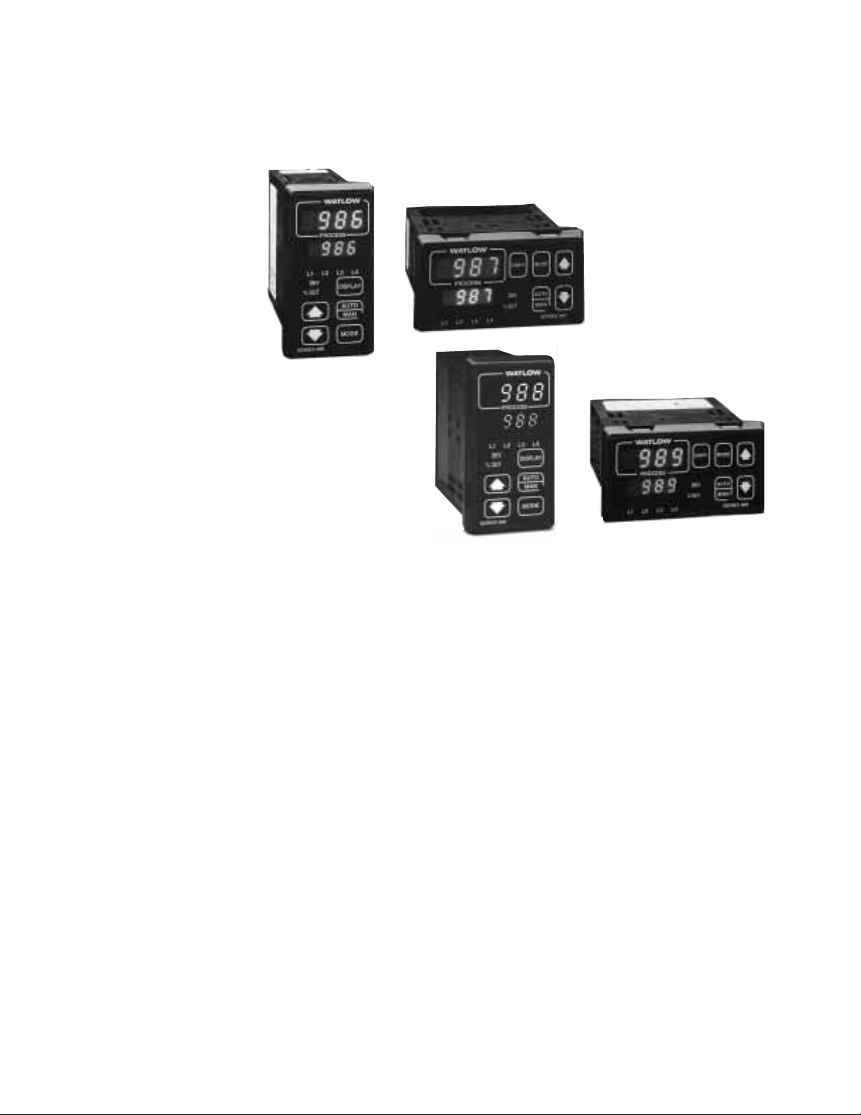
Figure Int.1 The Series 988
Controllers.
Watlow’s Series 988 controllers set a new standard in the controller industry by packing an impressive array of features into an 1/8-DIN package.
No other controller offers the flexibility, compact size and durability of the
Series 988. It can control a wide variety of temperature and process applications, with a broad range of input and output options that allow control
of virtually any process variable.
The Series 988 is the only 1/8 DIN controller that can provide single-unit
cascade control of a process. Its other features include heater current
monitoring, remote set point input, ratio control and valve control through
slidewire feedback. The Series 988 also delivers expanded auto-tuning
capabilities, increased alarm functionality and several unique control algorithms.
When we refer to the “Series 988” controller, we refer also to the horizontal
and low-voltage versions of the Series 988: the 986, 987, 988 and 989. We
recommend that you read all of this manual’s introduction to familiarize
yourself with the conventions and content of this manual and the steps to
setting up a Series 988 controller. Make sure you understand the
“Caution” and “Warning” symbols we use in the book.
Introduction
WATLOW Series 988 User’s Manual i
Page 4

Introduction
˜
NOTE:
The 12-digit number
is printed on the top
of the stickers on
each side of the
controller’s case
and on the righthand or top circuit
board.
˜
NOTE:
The Menu Overview
in the Appendix
shows all the
menus and
prompts.
Using this Manual
This manual provides the information you will need to install and operate
a Series 988 controller.
If you need information about Series 988 configurations and model numbers, refer to the Appendix of this manual or, for more detailed information, to Optimizing Your Process System with the Series 988 Controller: An
Application Guide for the Watlow Series 988 Family.
If your Series 988 controller will be used for data communications, you
will also need our communications manual, Data Communications with the
Watlow Series 988 Family of Controllers (green cover).
Series 988 controllers are calibrated in the factory, but if you need to do
periodic calibration you will need our calibration manual, Calibrating
Watlow Process Controllers, (blue cover).
This manual explains the five steps of setting up a Series 988 controller:
1. Set and document all of the DIP switches, if applicable: Chapter 1.
2. Mount the controller: Chapter 2.
3. Wire and document the controller wiring: Chapter 2.
4. Configure and document the controller software: Chapters 3-6.
5. Run, test and adjust your application. Update documentation.
Chapters 7 and 8 and the Appendix provide detailed advice, definitions
and specifications along with application examples to help you optimize
the safety and performance of your application. Use the Table of Contents
and Index to find specific information.
Document Every Step
The Series 988 provides powerful and complex features. Carefully document each step of the setup and any subsequent changes. This will make
it much easier to change, adjust and troubleshoot your application.
Make the configuration documentation available to engineers and technicians, on all shifts, who may need to work with the Series 988. We provide
space in this manual to record configurations. You may prefer to photocopy the blank forms and keep them in a separate binder. However you
maintain your documentation, be sure to replace all old copies of the documentation with updated versions whenever the controller configuration is
changed.
ii WATLOW Series 988 User’s Manual
Introduction
Page 5

Introduction
Notes, Cautions and Warnings
We use note, caution and warning symbols throughout this book to draw
your attention to important operational and safety information.
A bold text “NOTE” marks a short message in the margin to alert you to
an important detail.
A bold text “CAUTION” safety alert appears with information that is
important for protecting your equipment and performance. Be especially
careful to read and follow all cautions that apply to your application.
A bold text “WARNING” safety alert appears with information that is
important for protecting you, others and equipment from damage. Pay
very close attention to all warnings that apply to your application.
The ç symbol (an exclamation point in a triangle) precedes a general
CAUTION or WARNING statement.
The Ó symbol (a lightning bolt in a triangle) precedes an electric shock
hazard CAUTION or WARNING safety statement.
Technical Assistance
If you encounter a problem with your Watlow controller, review all of your
configuration information for each step of the setup to verify that your
selections are consistent with your applications.
If the problem persists after checking all the steps, you can get technical
assistance by calling Watlow Controls at (507) 454-5300, between 7 a.m.
and 5 p.m. CST, and asking for an applications engineer. When you call
have the following information on hand: the controller’s model number
(the 12-digit number is printed on the top of the stickers on each side of
the controller’s case and on the right-hand or top circuit board); your
user’s manual; all configuration information; and the Diagnostics Menu
readings.
We Value Your Feedback
Your comments and suggestions on this manual are welcome. Please send
them to, Technical Writer, Watlow Controls, 1241 Bundy Blvd., P.O. Box
5580, Winona, MN 55987-5580 or call (507) 454-5300 or fax (507) 452-
4507. The Series 988 User’s Manual is copyrighted by Watlow Winona,
Inc., © March 1999, with all rights reserved. (1657)
Introduction
WATLOW Series 988 User’s Manual iii
Page 6
Chapter 1 Hardware Setup
DIP Switch Locations and Functions
The Watlow Series 988 has at least one and as many as six dual in-line
package (DIP) switches inside the controller, depending on the model
number. They allow users to configure the controller for a variety of input
sensors, to provide power for external signal conditioners or to lockout
front panel access to some functions.
To set any DIP switch:
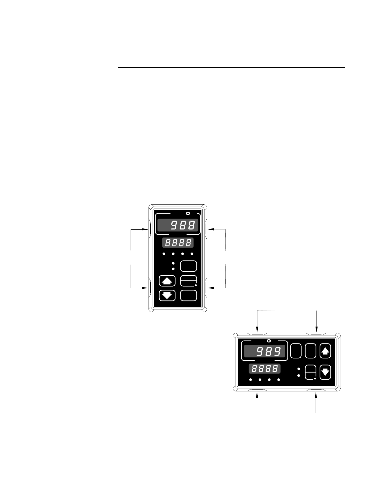
• Remove the controller from the case by pressing firmly on the two release
tabs on one side or the top of the bezel until they unsnap. Then firmly
press the two release tabs on the opposite side or the bottom of the control until they unsnap. You will need to gently rock the bezel back and
forth to release it from the chassis.
• Use the illustrations on the following pages to locate and set each DIP switch.
Figure 1.1 - Press
the release tabs to
remove the controller chassis.
Release
Tabs
A
W
PROCESS
L1 L2 L3 L4
DEV
% OUT
SERIES 988
W
TL
DISPLAY
AUTO
MAN
MODE
Release
Tabs
W
A
TL
W
PROCESS
L1 L2 L3 L4
Release
Tabs
DEV
% OUT
DSPY
MODE
AUTO
MAN
SERIES 989
Hardware Setup, Chapter 1
Release
Tabs
WATLOW Series 988 User’s Manual 1.1
Page 7
DIP Switches
˜
NOTE:
The Input 2 DIP
switch is mounted
upside down.
˜
NOTE:
Only controllers
with the indicated
model numbers
have these DIP
switches.
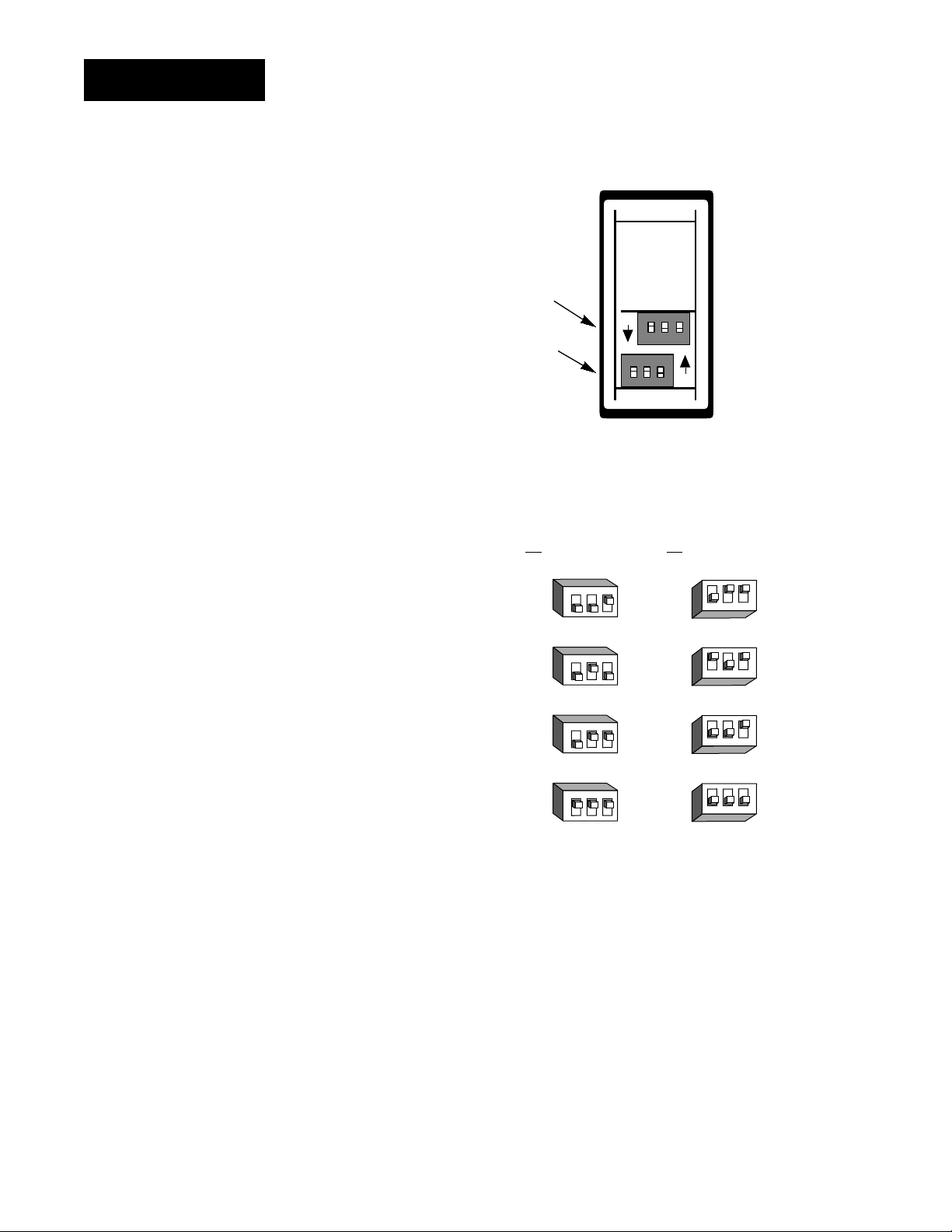
Figure 1.2 Input DIP switches.
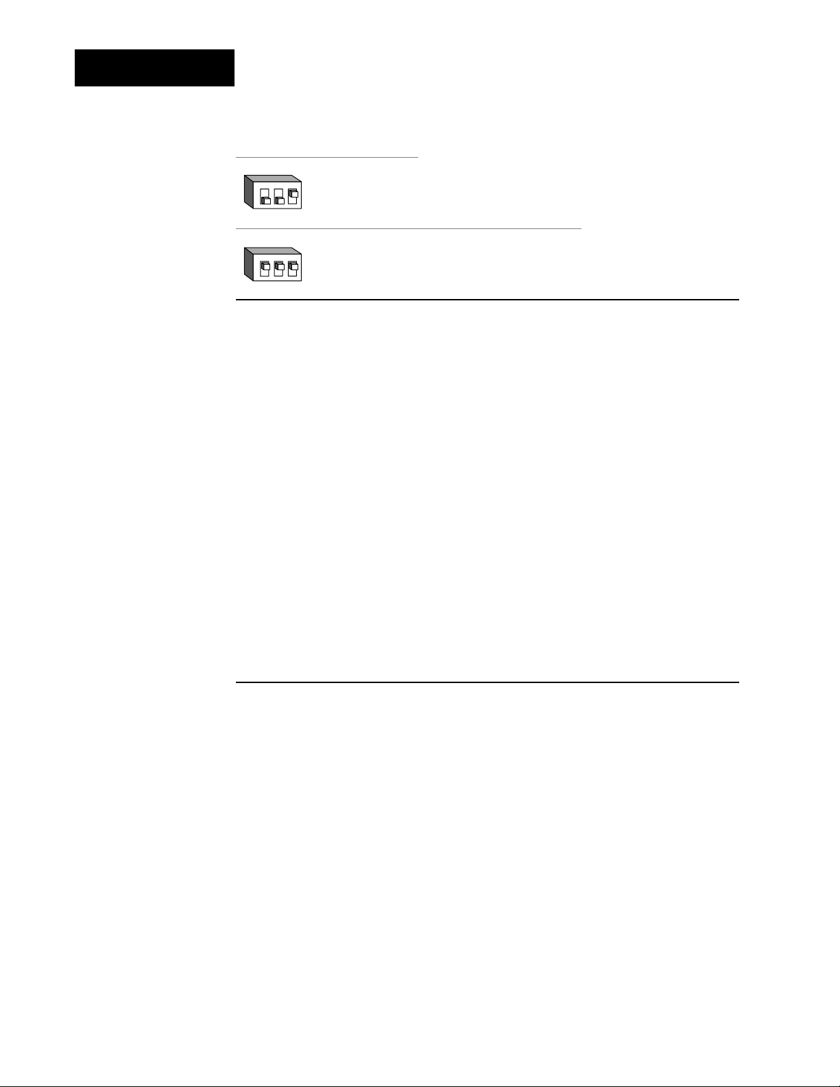
1. Set the input DIP
switches to match the
Input 2 DIP
sensors you are using
in your application.
Only controllers with
Input 1 DIP
model number 98_ _2_ _ _-_ _ _ _ or 98_ __2_ _-_ _ _ _ have an
input DIP switch.
RTD (100 Ω)
thermocouple: R, S or B
thermocouple: J, K, T, N, E, C, D, Pt2
or 0-50mV (high impedance)
0-20 or 4-20mA; 0-5, 1-5 or 0-10V
ON
ON
Controller Chassis
Rear View
Input 1 Input 2
(98 _ _-2_ _ _-_ _ _ _)(98 _ _-_2_ _-_ _ _ _)
123
O
N
↑
123
O
N
↑
123
O
N
↑
123
O
N
↑
↑
N
O
123
↑
N
O
123
↑
N
O
123
↑
N
O
123
1.2 WATLOW Series 988 User’s Manual
Hardware Setup, Chapter 1
Page 8
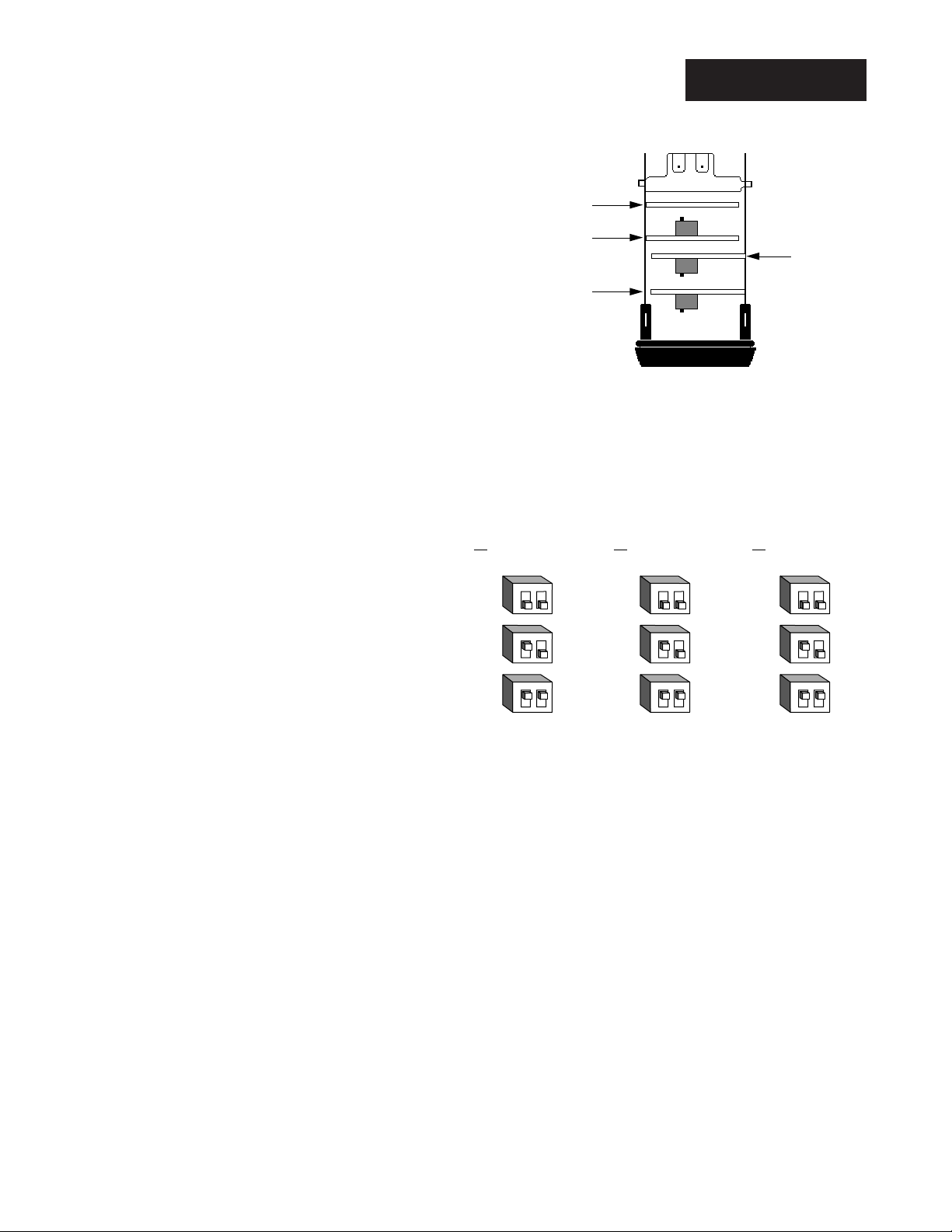
Output 2
Option B oa r d a nd D IP
Output 4
Option B oa r d a nd D IP
Con t ro ller Chassis
Top View (986 & 988)
Left-side View (987 & 989)
Output 3
Option B oa r d a nd D IP
Output 1
Option Board
offon
on
on
off
off
˜
NOTE:
For other voltages
or current settings
contact the factory.
˜
DIP Switches
2. Set DIP switches for
outputs equipped with
an external signal conditioner power supply.
Only controllers with
model number 98_ _-_
_ _T-_ _ _ _, 98_ _-_ _ _
_-T_ _ _ or 98_ _-_ _ _
_-_T_ _ have an external signal conditioner
power supply.
NOTE:
Only controllers
with the indicated
model numbers
have these DIP
switches.
Figure 1.3 External signal conditioner power supply DIPs.
Output 2 Output 3 Output 4
(98 _ _-_ _ _T-_ _ _ _) (98 _ _-_ _ _ _-T_ _ _) (98 _ _-_ _ _ _-_T_ _)
12
O
N
↑
12
O
N
↑
12
O
N
↑
20V ± 5% @ 30mA
12V ± 5% @ 30mA
5V ± 5% @ 30mA
12
O
N
↑
12
O
N
↑
12
O
N
↑
12
O
N
↑
12
O
N
↑
12
O
N
↑
3. When the DIP switches are set, gently insert the controller chassis into
the case and push it firmly into place until all four tabs snap into place.
Hardware Setup, Chapter 1
WATLOW Series 988 User’s Manual 1.3
Page 9
DIP Switches
M
ç
CAUTION:
The lockout DIP
switch makes the
Setup and Factory
menus unavailable.
Configure all the
Setup and Factory
menus before locking them out.
Failure to do so
could result in damage to equipment in
the event of a setup
error.
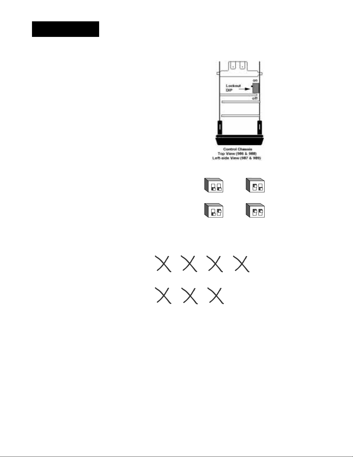
4. The lockout DIP switch
hides the Setup Menus
(Input, Output, Global and
Communications) and the
Factory Menus (Panel
Lockout, Diagnostics and
Calibration). All units have
a lockout DIP switch.
Figure 1.4 Lockout DIP switch.
12
O
N
no hardware lockout or
↑
(Switch 1 has no effect.)
12
O
N
lockout Setup and Factory menus or
↑
(Switch 1 has no effect.)
Input
[InPt]
[`SEt]
Panel
Lockout
[PLOC]
[Fcty]
Output Global
[OtPt]
[`SEt]
[GLbL]
[`SEt]
Diagnostics Calibration
[diAG]
[Fcty]
[`CAL]
[Fcty]
Communications
[CO
[`SEt]
12
O
N
↑
12
O
N
↑
1.4 WATLOW Series 988 User’s Manual
Hardware Setup, Chapter 1
Page 10
Chapter 2 Installation and Wiring
W
A
TL
˜
NOTE:
Space panel
cutouts at least 1.66
inches (42.2mm)
apart.
˜
NOTE:
Adjustable mounting brackets can be
side-mounted.
W
PROCESS
L1 L2 L3 L4
DEV
% OUT
SERIES 988
2.18"
(55 mm)
DISPLAY
AUTO
MAN
MODE
4.03"
(102mm)
(102mm)
W
A
TL
W
PROCESS
L1 L2 L3 L4
4.03"
DEV
% OUT
DSPY
MODE
AUTO
MAN
2.18"
(55 mm)
SERIES 989
˜
NOTE:
Holes can be cut in
the panel using a
Greenlee 1/8 DIN
Hydraulic Kit
#60068 (punch
#60069, die #60070).
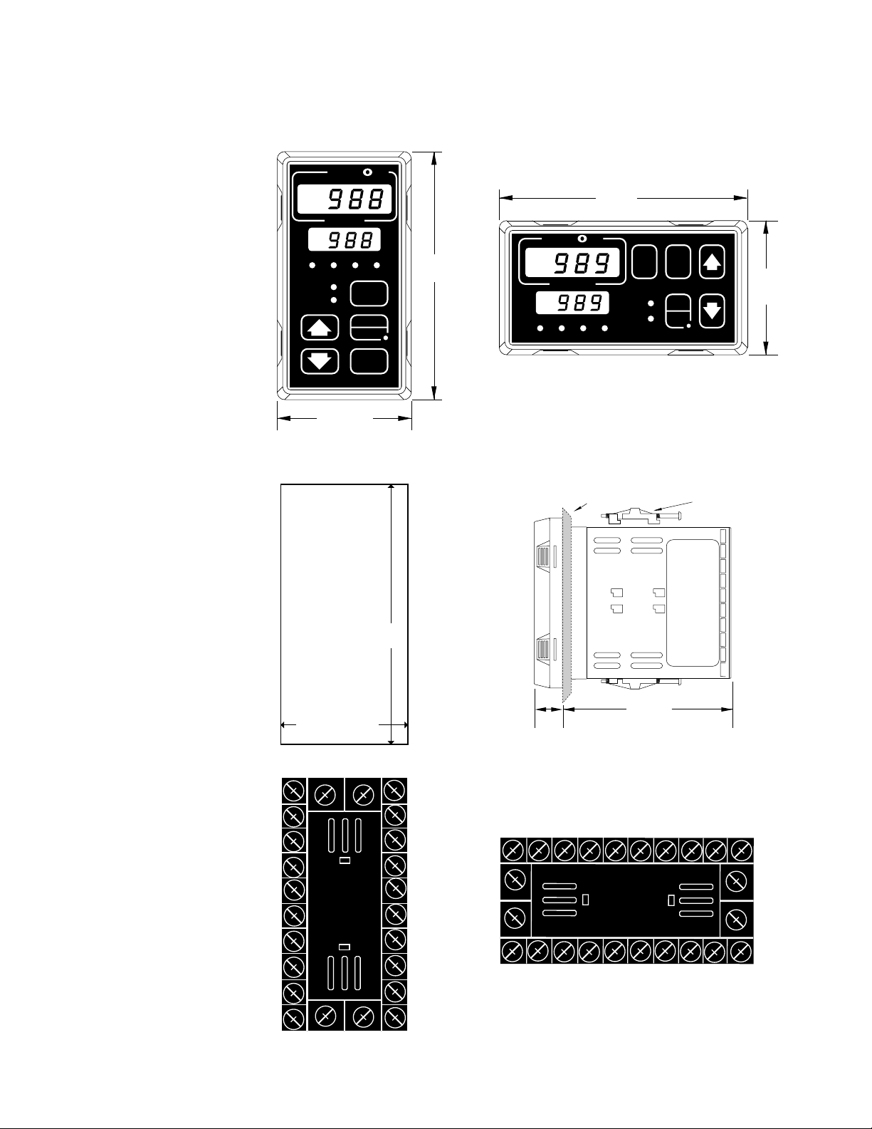
Figure 2.1 Series 988 and
Series 989
dimensions and
terminal number
layout.
Panel Cutout
Maximum Panel
Thickness
0.38" (9.65mm)
3.62" + 0.03 -0.00
(92mm + 0.8)
1.77 + 0.02 -0.00
(45mm + 0.6)
1
21
2
3
4
5
6
7
8
9
231024
Panel
0.68"
(17 mm)
11
22
12
13
14
15
16
17
18
19
10
98765432
23
24
19 18 17 16 15 14 13 12
20
4.06"
(103 mm)
Adjustable
Mounting Bracket
21
22
1
11
Installation and Wiring, Chapter 2
20
WATLOW Series 988 User’s Manual 2.1
Page 11
Installation
Panel
Adjustable
Mounting Bracket
Bezel
External Gasket
Mounting Collar
Release Tabs
Top and Bottom (986 or 988)
or Side (987 or 989) View
Mounting Slots
Side (986 or 988)
or Top and Bottom (987 or 989) View
˜
NOTE:
Removing the controller chassis from
its case makes
mounting easier.
Installing the Series 988
Installing and mounting requires access to the back of the panel.
1. Make a panel cutout using the panel cutout dimensions from the previous page.
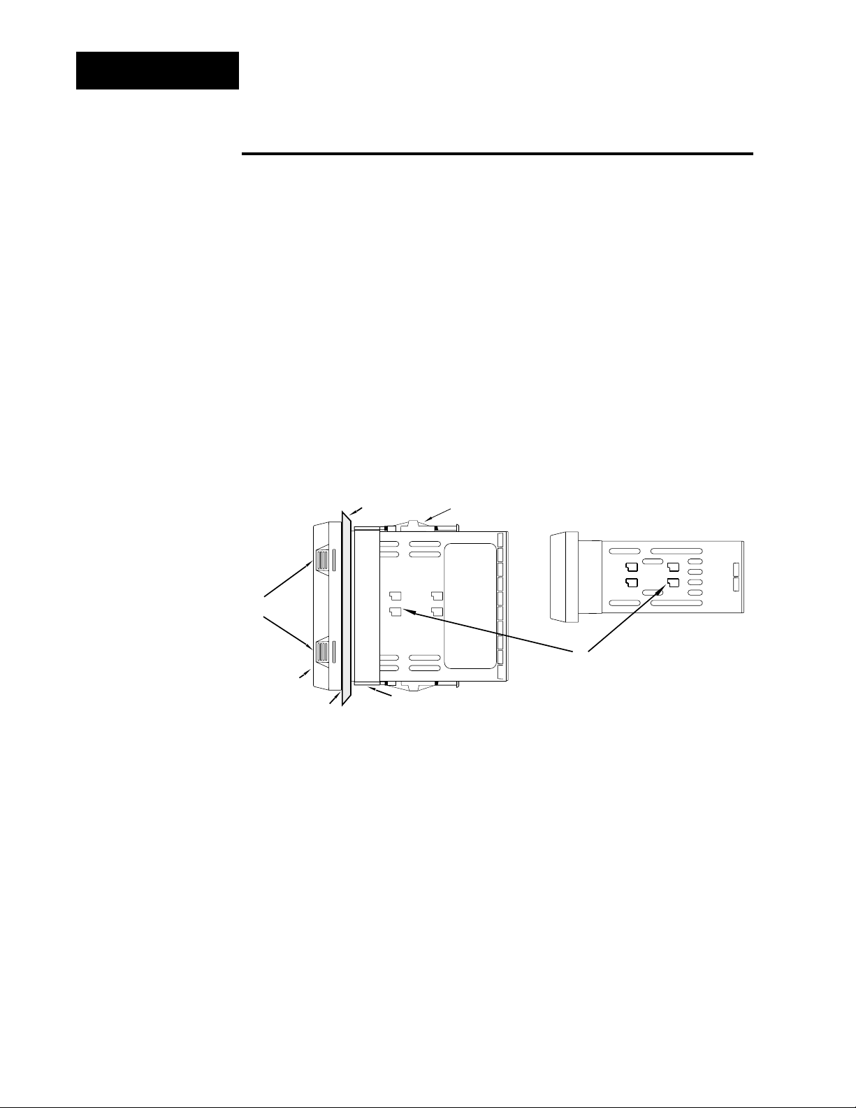
2. To remove the controller chassis from its case, press in firmly on the two
tabs on one side or the top of the bezel until they unsnap, then unsnap
the two tabs on the opposite side or the bottom. Pull the chassis out of
the case by gently rocking it.
3. Slide the case into the panel cutout. Check to see that the gasket is not
twisted, and is seated within the case bezel flush with the panel. Slide
Figure 2.2 Side and top view.
2.2 WATLOW Series 988 User’s Manual
Installation and Wiring, Chapter 2
Page 12

Installation
the mounting collar over the back of the control.
4. Loosen the mounting bracket screws enough to allow for the mounting
collar and panel thickness. Place each mounting bracket into the
mounting slots (head of the screw facing the back of the controller).
Push each bracket backward then down to secure it to the control
case. To guarantee a proper NEMA 4X seal, Series 986 and 988
units (vertical) must have the mounting brackets located on either
side of the unit. When installing Series 987 and 989 units (horizontal) the brackets must be on the top and bottom of the unit.
ç
CAUTION:
Follow the installation procedure
exactly to guarantee
a proper NEMA 4X
seal. Make sure the
gasket between the
panel and the rim of
the case is not
twisted and is seated properly. Failure
to do so could
result in damage to
equipment.
5. Make sure the case is seated properly. Tighten the installation screws
firmly against the mounting collar to secure the unit. To ensure a
NEMA 4X seal, there should be no space between the bezel and
panel. Overtightening the screws will distort the case and make it diffi-
cult to remove or replace the controller.
6. Make sure the inside gasket is seated properly and not twisted.
Insert the controller chassis into its case and press the bezel until all
four tabs snap.
7. To release the mounting brackets, loosen the mounting bracket screws
and push the brackets forward, then pull it up and out.
Installation and Wiring, Chapter 2
WATLOW Series 988 User’s Manual 2.3
Page 13

fuse
22
21
earth ground
11
L2L1
+
-
∫
Wiring
Wiring the Series 988
WARNING:
To avoid potential
electric shock, use
National Electric
Code (NEC) safety
practices when
wiring and connecting this unit to a
power source and
to electrical sensors
or peripheral
devices. Failure to
do so could result
in injury or death.
˜
NOTE:
Input-to-output isolation is defeated
when the external
signal conditioner
power supply is
used to power a
transmitter connected to input 1 or
input 2.
Wiring options depend on the model number and DIP switch settings.
Check the terminal designation stickers on either side of the controller
and compare your model number to those shown here and with the model
number breakdown on the inside back cover of this manual.
Input-to-output Isolation
The Series 988 uses optical isolation between the analog inputs and the
controller outputs/digital input. This isolation provides a 500VÅ (ac) barrier to prevent ground loops when using grounded sensors and/or peripheral equipment.
Here is a breakdown of the isolation barriers:
• Analog inputs 1 and 2 are grouped together.
• Outputs 1 through 4 and the standard event input are grouped together.
This does not apply to Output 4 when configured as communications.
• The digital communications output (4) is separate from the above
groups.
Power Wiring
100 to 240V‡‡(ac/dc) nominal, (85 to 264 actual)
Vertical Package 98 8 _ - _ _ _ _ - _ _ _ _
Horizontal Package 98 9 _ - _ _ _ _ - _ _ _ _
Figure 2.4 Power wiring.
2.4 WATLOW Series 988 User’s Manual
24 to 28 V‡‡(ac/dc) nominal, (20 to 30 actual)
Vertical Package 98 6
Horizontal Package 98 7
_ - _ _ _ _ - _ _ _ _
_ - _ _ _ _ - _ _ _ _
Installation and Wiring, Chapter 2
Page 14

Sensor Installation Guidelines
Wiring
ç
CAUTION:
The Series 988 will
not function with
two grounded thermocouple inputs.
Avoid using a
grounded thermocouple for both
input 1 and input 2.
Failure to follow this
guideline could
result in damage to
equipment.
NOTE:
Input-to-output isolation is defeated
when the external
signal conditioner
power supply is
used to power a
transmitter connected to input 1 or
input 2.
Maintain isolation between input 1 and input 2 to prevent a ground loop.
A ground loop may cause incorrect readings, dashes across the upper display or the display of error codes.
Thermocouple input: Extension wire for thermocouples must be of the
same alloy as the thermocouple itself to limit errors.
Using grounded thermocouples for both input 1 and input 2 may create
ground loop problems. To correct this problem, replace at least one of the
grounded thermocouples with an ungrounded thermocouple. If the application requires grounded thermocouples, use an isolated transmitter,
such as a Watlow Gordon 5702 isolated transmitter.
RTD (100 Ω) input: Each 1Ω of lead wire resistance can cause a +2°C
error when using a two-wire RTD. A three-wire RTD sensor overcomes this
problem. All three wires must have the same electrical resistance (i.e.,
same gauge, same length, multi-stranded or solid, same metal).
Process input: Isolation must be maintained between input 1 and input
2. If both input 1 and input 2 are used as process inputs, a separate
power supply and transmitter must be used for each input. Output option
T (external signal conditioner power supply) can be used to supply power
for only one input.
Installation and Wiring, Chapter 2
WATLOW Series 988 User’s Manual 2.5
Page 15
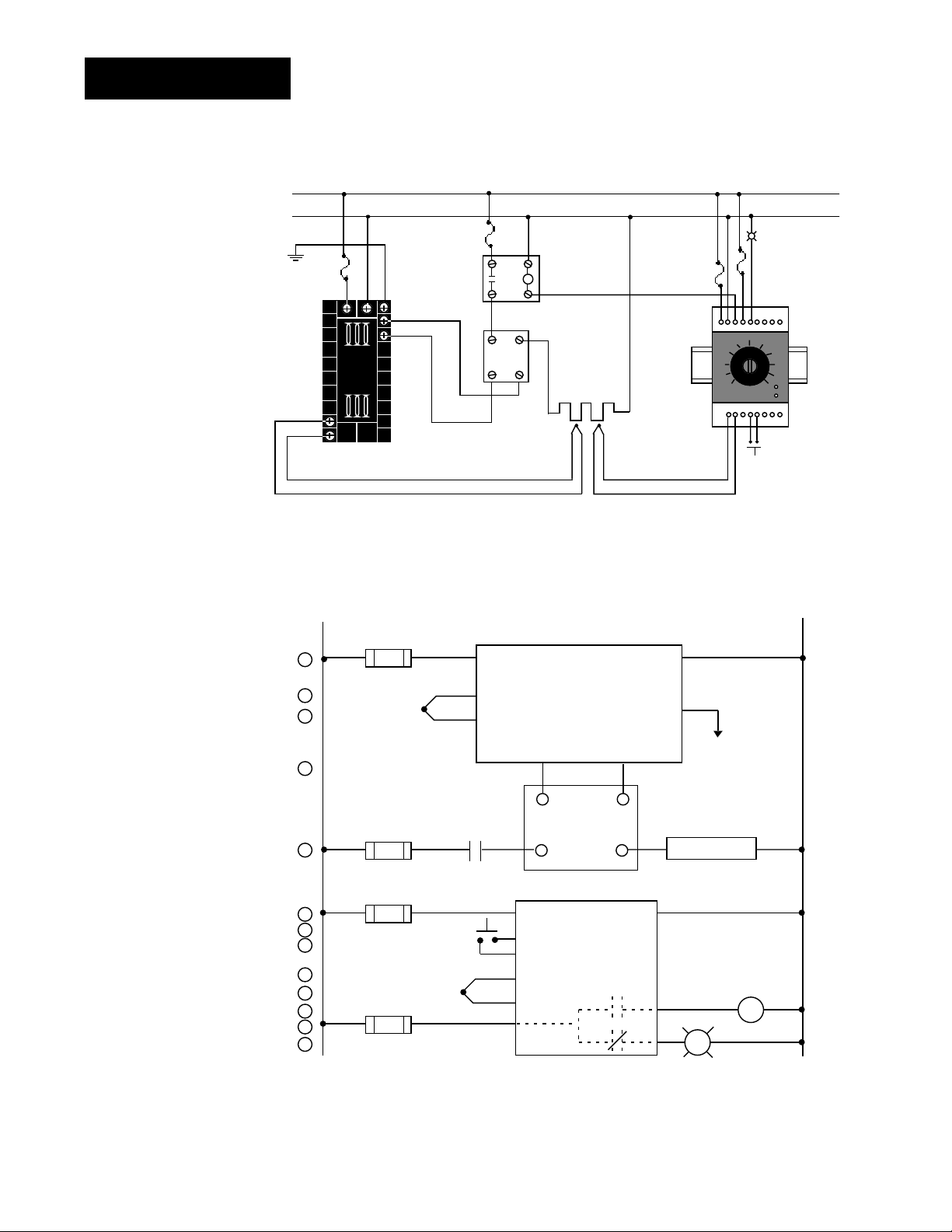
Wiring Example
∫
WARNING:
To avoid potential
electric shock, use
National Electric
Code (NEC) safety
practices when
wiring and connecting this unit to a
power source and
to electrical sensors or peripheral
devices. Failure to
do so could result
in injury or death.
ç
WARNING:
Install high or low
temperature limit
control protection
in systems where
an over temperature fault condition
could present a fire
hazard or other hazard. Failure to
install temperature
limit control protection where a potential hazard exists
could result in damage to equipment,
property and injury
to personnel.
ç
WARNING:
To avoid damage to
property and equipment, and/or injury
of loss of life, use
National Electric
Code (NEC) standard wiring practices to install and
operate the Series
988. Failure to do
so could result in
such damage,
and/or injury or
death.
Figure 2.6 System wiring
example.
L1
120VÅ (ac)
L2
earth ground
(+)
9
10
(-)
red
120VÅ (ac)
1
2
3
4
5
6
7
8
9
10
11
12
13
high-limit
mechanical
fuse
2221
11
12
(+)
(-)
13
988A-10CA-AARR
rear view
L1
1
1
1 2
1
process sensor limit sensor
3
4
(+)
5
(-)
1 CR-1
8
11
17
coil
contactor
10+11
heater
Series 92
limit control
R
15
13 14
-
normally open
momentary switch
1CR
16
SSR-240-10A-DC1
out
12
43
in
21 22
9
10
910
12
13
(+)
14
(-)
15
dc input
SSR
heater
Series 988
988A-10CA-AARR
temperature control
12 13
67
in
3-32VÎ (dc)
(+)
out
24-240VÅ (ac)
12
13
14
10
11
4
92A3-1DJ1-0000
limit control
11
SSR-240-10A-DC1
solid-state relay, dc input
(-)
92A3-1DJ1-0000
3
5
18
high-temperature light
high-temperature
light
optional
L2
2
2
2
2
2.6 WATLOW Series 988 User’s Manual
Installation and Wiring, Chapter 2
Page 16
ç
WARNING:
To avoid damage to
property and equipment, and/or injury
of loss of life, use
National Electric
Code (NEC) standard wiring practices to install and
operate the Series
988. Failure to do
so could result in
such damage,
and/or injury or
death.
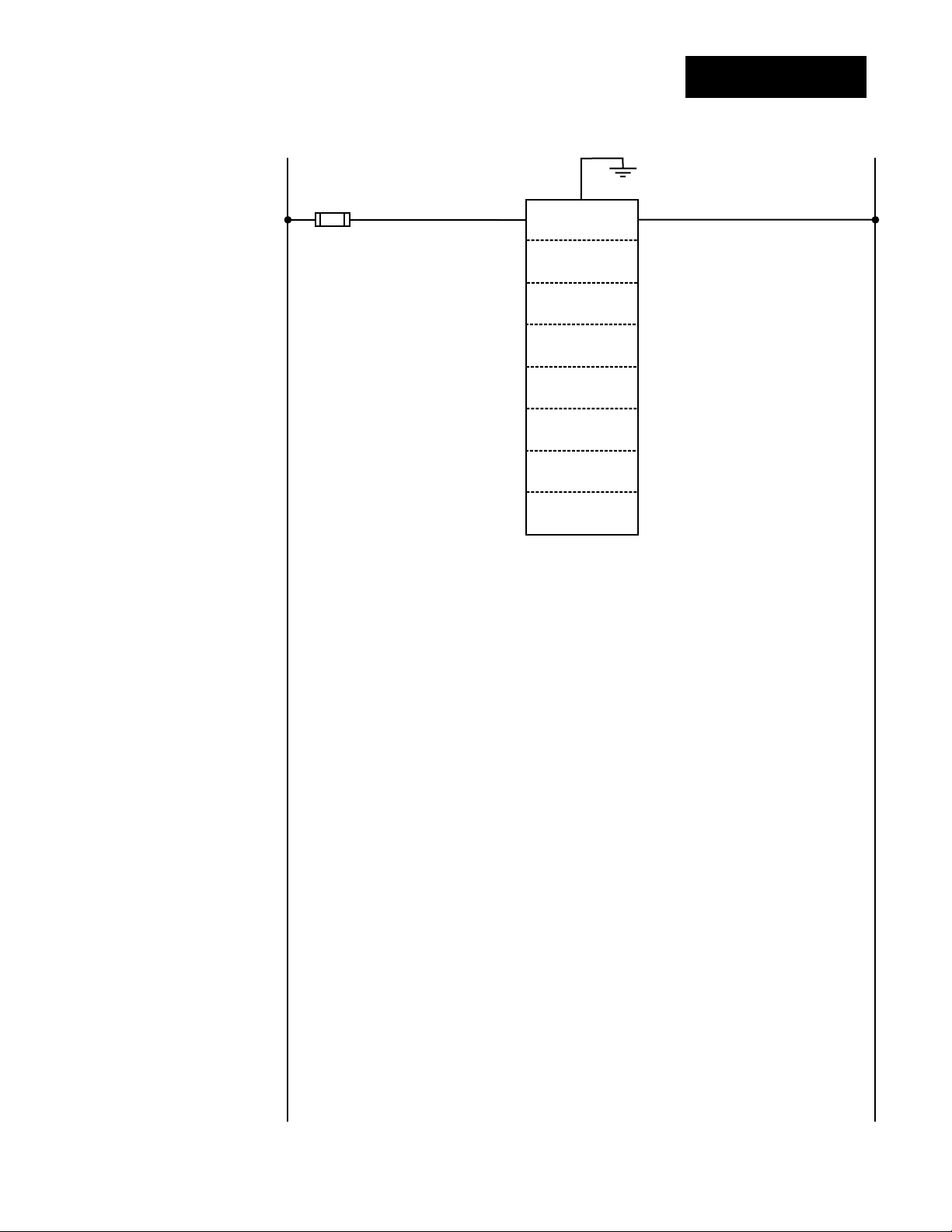
Wiring Notes
L1 L2
earth ground
11
21 22
power
˜
NOTE:
Sketch in your
application on this
page or a copy of it.
See wiring examples in this chapter
and in the Appendix.
Figure 2.7 Wiring notes.
Installation and Wiring, Chapter 2
WATLOW Series 988 User’s Manual 2.7
Page 17
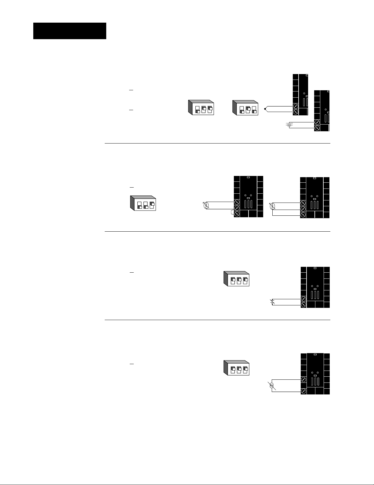
Input 1 Wiring
9
10
+
-
0-50mV
˜
NOTE:
Successful installation requires five
steps:
• Model number and
software choice
(Appendix);
• DIP switch settings (Chapter 1);
• Sensor match
(Chapter 2 and
Appendix);
• Sensor installation
(Chapter 2); and
• Wiring (Chapter 2).
Figure 2.8a — Thermocouple or 0-50mV (high impedance)
Thermocouple only
98 _ _ - 1 _ _ _ - _ _ _ _ (no DIP switches)
Universal signal conditioner
98 _ _ - 2 _ _ _ - _ _ _ _
Input impedance: 20MΩ
123
O
N
↑
J, K, T, N, C, E, D, Pt2,
0-50mV DIP Settings
123
O
N
↑
R, S, B
DIP Settings
+
9
-
10
Figure 2.8b — RTD (2- or 3-wire) (100 Ω)
Universal signal conditioner
98 _ _ - 2 _ _ _ - _ _ _ _
123
O
N
↑
DIP Switch
Setting
Jumper
#9 to #10
for 2-wire
RTD
8
S1
9
S2
10
8
S1
S2
9
10
S3
Figure 2.8c — 0-5V
ÎÎ
, 1-5VÎÎor 0-10VÎÎ(dc) Process
Universal signal conditioner
98 _ _ - 2 _ _ _ - _ _ _ _
123
O
N
Input impedance: 10KΩ
↑
DIP Switch
Setting
Figure 2.8d — 0-20mA or 4-20mA Process
Universal signal conditioner
98 _ _ - 2 _ _ _ - _ _ _ _
Input impedance: 7Ω
123
O
N
↑
DIP Switch
Setting
9-+
10
-
8
10
+
2.8 WATLOW Series 988 User’s Manual
Installation and Wiring, Chapter 2
Page 18
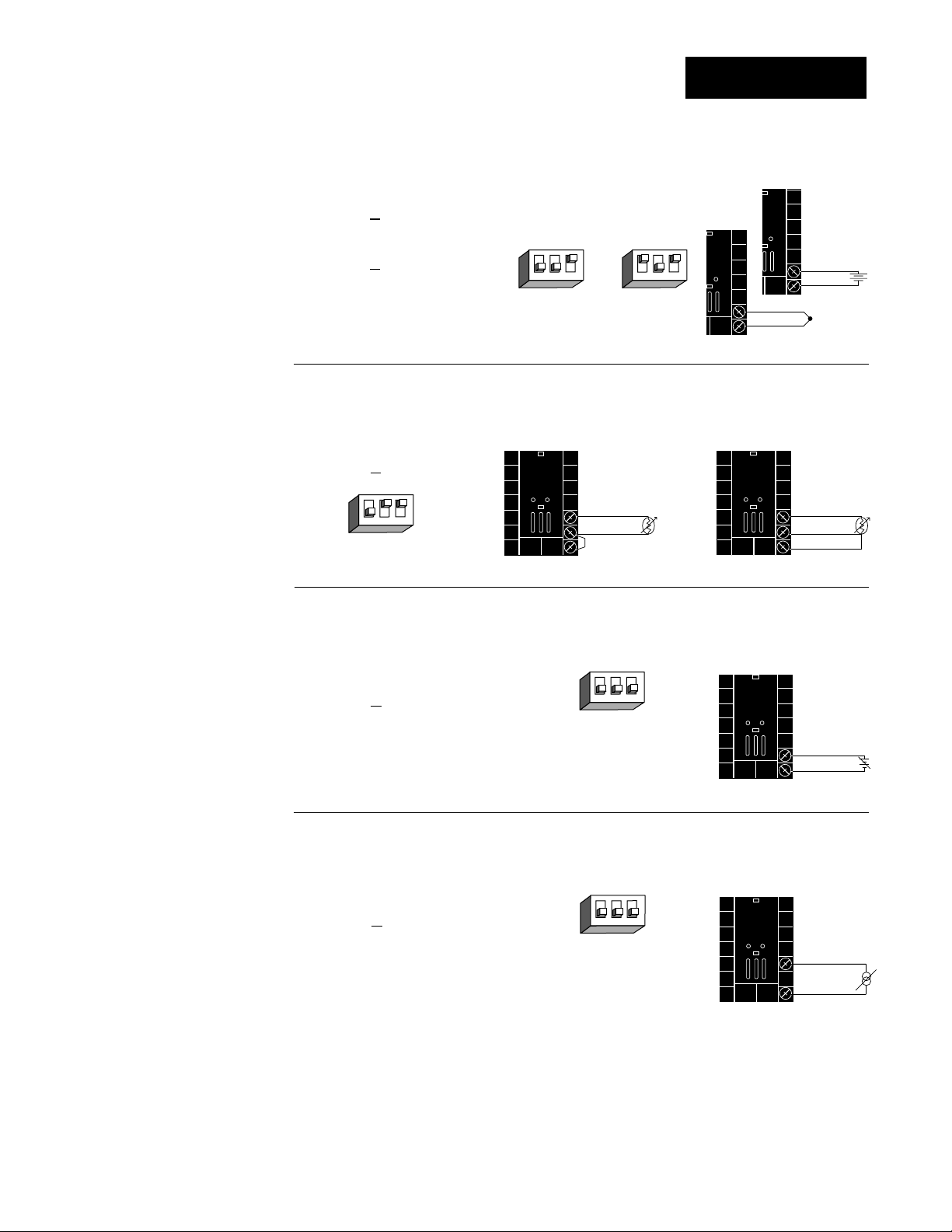
Input 2 Wiring
19
20
18
S2
S1
NOTE:
Successful installation requires five
steps:
• Model number and
software choice
(Appendix);
• DIP switch settings (Chapter 1);
• Sensor match
(Chapter 2 and
Appendix);
• Sensor installation
(Chapter 2); and
• Wiring (Chapter 2).
Figure 2.9a — Thermocouple or 0-50mV (high impedance)
Thermocouple only
98 _ _ - _ 1 _ _ - _ _ _ _ (no DIP switches)
Universal signal conditioner
98 _ _ - _ 2 _ _ - _ _ _ _
Input impedance: 20MΩ
J, K, T, N, C, E, D, Pt2,
0-50mV DIP Settings
↑
N
O
123
DIP Settings
R, S, B
↑
N
O
123
19
20
19
+
-
20
0-50mV
+
-
Figure 2.9b — RTD (2- or 3-wire) (100 Ω)
Universal signal conditioner
98 _ _ - _ 2 _ _ - _ _ _ _
↑
N
O
123
DIP Switch
Setting
Jumper
#19 to #20
for 2-wire
RTD
18S2S1
19
S3
20
Figure 2.9c —
Universal signal conditioner
98 _ _ - _ 2 _ _ - _ _ _ _
0-5VÎÎ, 1-5VÎÎor 0-10VÎÎ(dc) Process
↑
N
O
123
DIP Switch
Setting
Input impedance: 10KΩ
Figure 2.9d — 0-20mA or 4-20mA Process
Universal signal conditioner
98 _ _ - _ 2 _ _ - _ _ _ _
DIP Switch
Input impedance: 7Ω
Setting
↑
N
O
123
19-+
20
18
20
-
+
Installation and Wiring, Chapter 2
WATLOW Series 988 User’s Manual 2.9
Page 19
20
19
T3
T1
T2
Phase
dot
Input 2 Wiring
20
19
L2
L1
CT
Load wire
Center leg not used
19
20
18
CW
CCW
Wiper
AC Load
19
20
0 to 5A
AC
0 to
20mA
A
Bk
Red
Red
Wh Bk
Bk Wh
Bk
16-0176
Transformer
CT
CT
T1
T3
T2
5A
20mA
19
20
NOTE:
See Chapter 8 for
information on
slidewire feedback.
˜
NOTE:
A process output
cannot be installed
on output 1 when
using a current
transformer input.
NOTE:
Successful installation requires five
steps:
• Model number and
software choice
(Appendix);
• DIP switch settings (Chapter 1);
• Sensor match
(Chapter 2 and
Appendix);
• Sensor installation
(Chapter 2); and
• Wiring (Chapter 2).
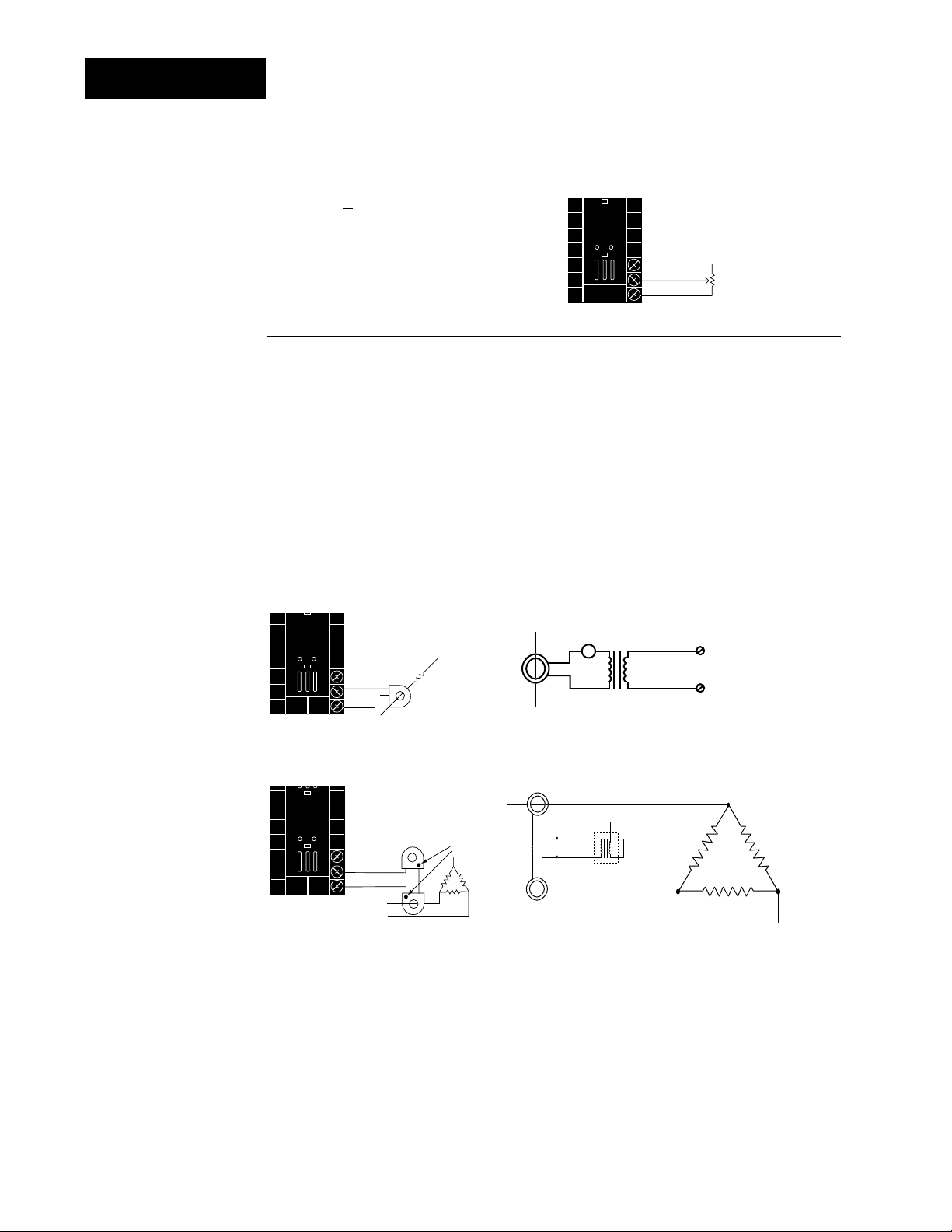
Figure 2.10a — Slidewire Feedback or Potentiometer Input
98 _ _ - _ 3 _ _ - _ _ _ _
Figure 2.10b — Current Transformer Input
98 _ _ - _ 4 _ _ - _ _ _ _
The current transformer must be purchased separately. Watlow current
transformer part number 16-0246 (up to 50 amps).
Systems that use more than 50 Amps need an interstage transformer.
For example, if you use a 300A current transformer, part #16-0073, and
an interstage transformer, part #16-0176, the 300A current transformer
provides a 5A signal to the interstage transformer. In turn, the transformer sends a 20mA maximum signal to the controller.
Single-phase Single-phase current sensing up to 300 amps
3-phase using 2 current transformers 3-phase current sensing up to 300 amps.
2.10 WATLOW Series 988 User’s Manual
Installation and Wiring, Chapter 2
Page 20
Event Input 1 Wiring
NOTE:
Successful installation requires five
steps:
• Model number and
software choice
(Appendix);
• DIP switch settings (Chapter 1);
• Sensor match
(Chapter 2 and
Appendix);
• Sensor installation
(Chapter 2); and
• Wiring (Chapter 2).
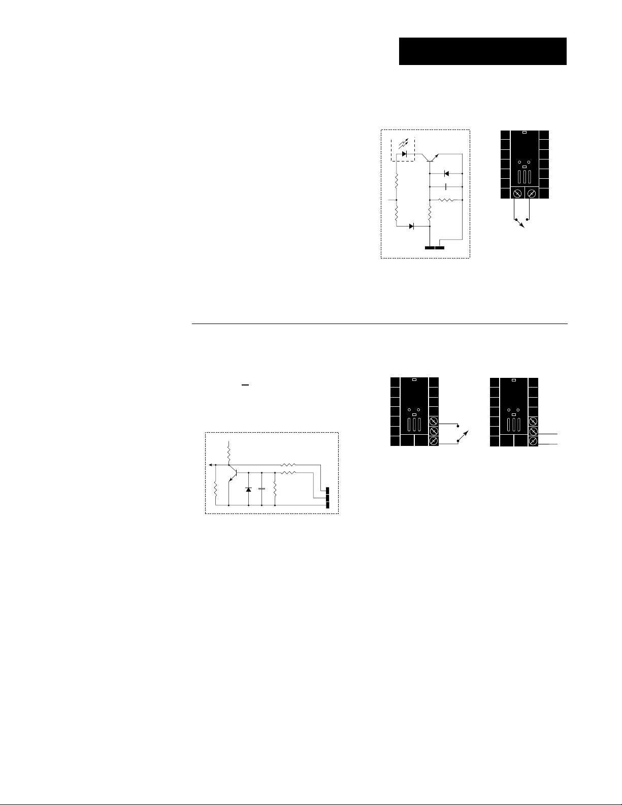
Figure 2.11a — Digital Event Input 1
Available on all units.
open 14-36VÎ (dc) Event Input 1 off
closed 0-3VÎ (dc) Event Input 1 on
+24VÎ (dc)
Internal Circuitry
Figure 2.10c — Digital Event Input 2
98 _ _ - _ 5 _ _ - _ _ _ _
4.99KΩ
10KΩ
OPTO
ISOLATOR
23
4.99KΩ
24
.01µf
750Ω
23 24
+-
open 0-3VÎ (dc) Event Input 2 off
closed 14-36VÎ (dc) Event Input 2 on
+5VÎ (VDC)
Internal Circuitry
100Ω
4.7KΩ
1KΩ
.01µf
750Ω
18
19
20
18
19
20
+
20
-
Installation and Wiring, Chapter 2
WATLOW Series 988 User’s Manual 2.11
Page 21
Output 1 Wiring
14
-
+
12
14
-
+
13
NOTE:
Successful installation requires five
steps:
• Model number and
software choice
(Appendix);
• DIP switch settings (Chapter 1);
• Sensor match
(Chapter 2 and
Appendix);
• Sensor installation
(Chapter 2); and
• Wiring (Chapter 2).
NOTE:
Switching inductive
loads (relay coils,
solenoids, etc.) with
the mechanical
relay or solid state
relay output options
requires using an
R.C. suppressor.
Watlow carries the
R.C. suppressor
Quencharc brand
name, which is a
trademark of ITW
Paktron. Watlow
Part No. 0804-0147-
0000.
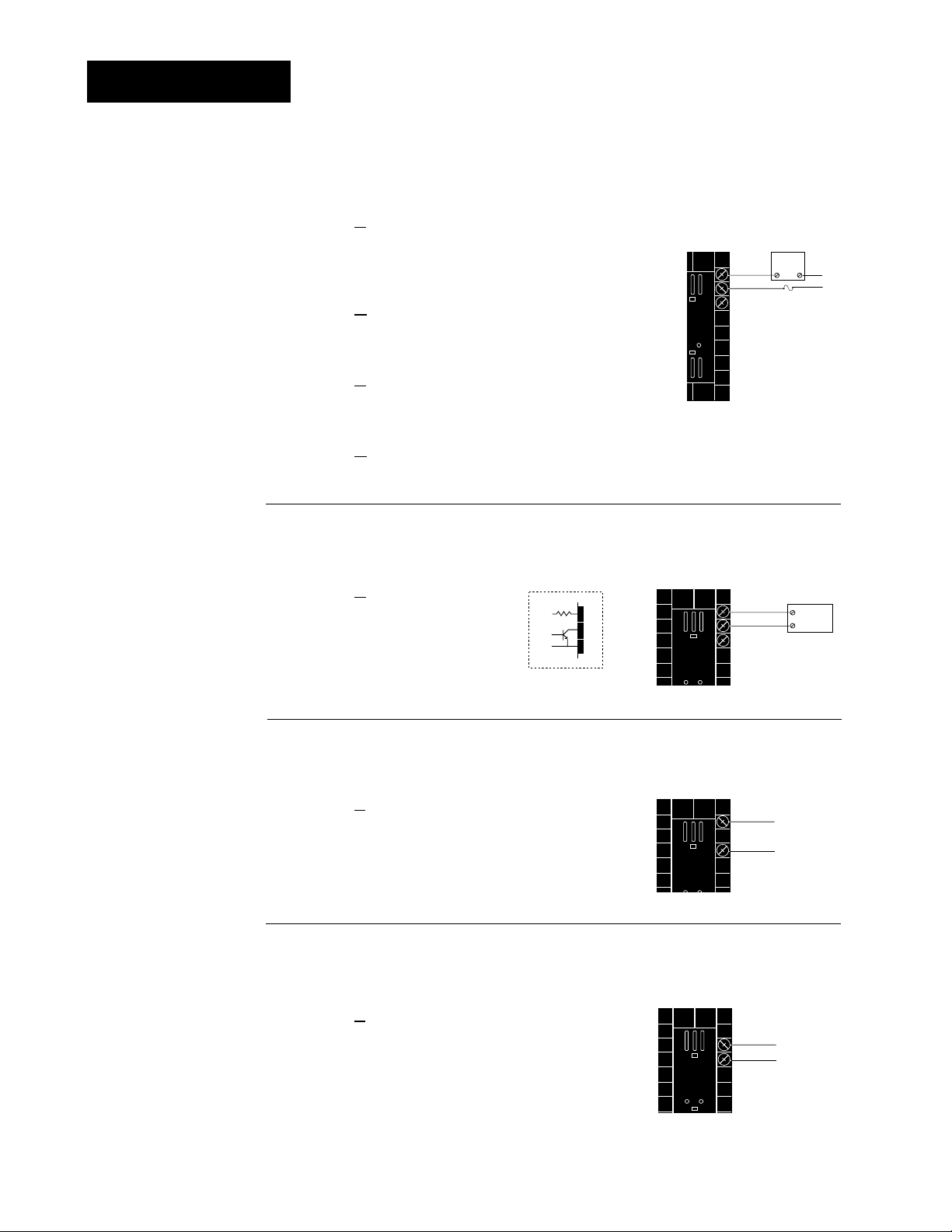
Figure 2.12a — AC Outputs
Solid-state Relay
with
Contact Suppression
98 _ _ - _ _ B _ - _ _ _ _
0.5 amps, minimum off-state impedance: 20KΩ
Electromechanical Relay
with
Contact Suppression
(Suppression between NO and COM contacts only)
98 _ _ - _ _ D _ - _ _ _ _
Form C, 5 amps, minimum off-state impedance: 20KΩ
Electromechanical Relay
without
Contact Suppression
98 _ _ - _ _ E _ - _ _ _ _
Form C, 5 amps off-state impedance: 31MΩ
Solid-state Relay
without
Contact Suppression
98 _ _ - _ _ K _ - _ _ _ _
0.5 amps, off-state impedance: 31MΩ
Figure 2.12b — Switched DC, Open Collector
98 _ _ - _ _ C _ - _ _ _ _
Maximum voltage: 42VÎÎ(dc)
Maximum current: 1A
19 to 32VÎ (dc)
+
790Ω
Internal Circuitry
12
13
14
Figure 2.12c — 0-20mA and 4-20mA Process
98 _ _ - _ _ F _ - _ _ _ _
External
Load
NO
12
13
COM
14
(#14 for D & E outputs only)
Fuse
NC
12
+
External
-
13
14
COM
L2
L1
Load
Maximum load impedance: 800Ω
Figure 2.12d — 0-5V
98 _ _ - _ _ F _ - _ _ _ _
Minimum load impedance: 1KΩ
2.12 WATLOW Series 988 User’s Manual
ÎÎ
, 1-5VÎÎand 0-10VÎÎ(dc) Process
Installation and Wiring, Chapter 2
Page 22
15
+
-
17
16
+
-
17
NOTE:
Successful installation requires five
steps:
• Model number and
software choice
(Appendix);
• DIP switch settings (Chapter 1);
• Sensor match
(Chapter 2 and
Appendix);
• Sensor installation
(Chapter 2); and
• Wiring (Chapter 2).
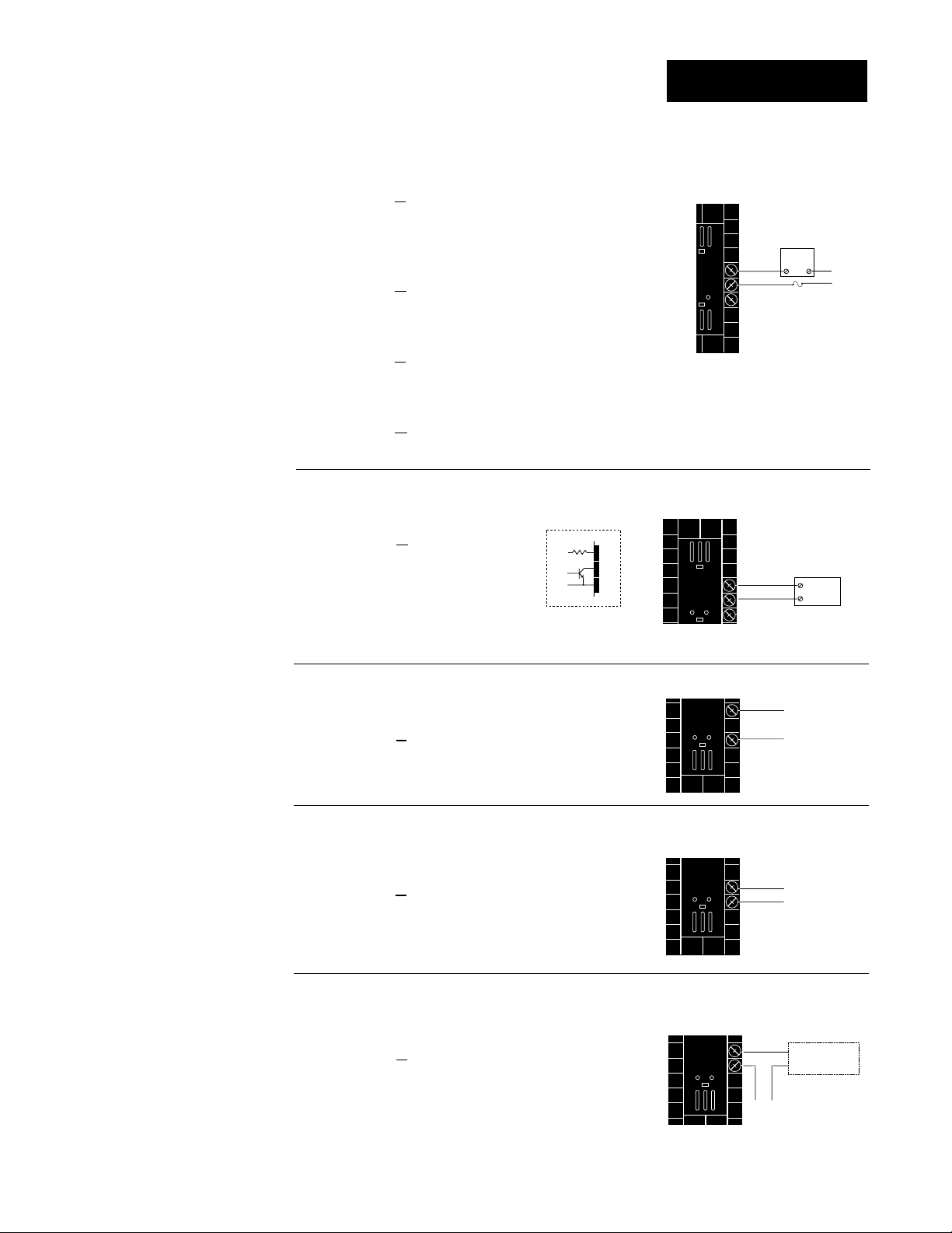
Figure 2.13a — AC Outputs
Solid-state Relay
with
Contact Suppression
98 _ _ - _ _ _ B - _ _ _ _
0.5 amps, minimum off-state impedance: 20KΩ
Electromechanical Relay
with
Contact Suppression
(Suppression between NO and COM contacts only)
98 _ _ - _ _ _ D - _ _ _ _
Form C, 5 amps, minimum off-state impedance: 20KΩ
Electromechanical Relay
without
Contact Suppression
98 _ _ - _ _ _ E - _ _ _ _
Form C, 5 amps off-state impedance: 31MΩ
Solid-state Relay
without
Contact Suppression
98 _ _ - _ _ _ K - _ _ _ _
0.5 amps, off-state impedance: 31MΩ
Output 2 Wiring
External
Load
15
NO
COM
16
NC
17
(#17 for D & E outputs only)
Fuse
L2
L1
NOTE:
Switching inductive
loads (relay coils,
solenoids, etc.) with
the mechanical
relay or solid state
relay output options
requires using an
R.C. suppressor.
Watlow carries the
R.C. suppressor
Quencharc brand
name, which is a
trademark of ITW
Paktron. Watlow
Part No. 0804-0147-
0000.
˜
NOTE:
Input-to-output isolation is defeated
when the external
signal conditioner
power supply is
used to power a
transmitter connected to input 1 or
input 2.
Figure 2.13b — Switched DC, Open Collector
98 _ _ - _ _ _ C - _ _ _ _
Maximum voltage: 42VÎÎ(dc)
Maximum current: 1A
19 to 32VÎ (dc)
+
790Ω
Internal Circuitry
15
16
17
15
+
External
-
16
17
Load
COM
Figure 2.13c — 0-20mA and 4-20mA Process
98 _ _ - _ _ _ F - _ _ _ _
Maximum load impedance: 800Ω
Figure 2.13d — 0-5V
ÎÎ
, 1-5VÎÎand 0-10VÎÎ(dc) Process
98 _ _ - _ _ _ F - _ _ _ _
Minimum load impedance: 1KΩ
Figure 2.13e — External Signal Conditioner Power Supply
98 _ _ - _ _ _ T - _ _ _ _
15
16
+
-
Loop powered
1
Transmitter
+V
2
4-20mA out
-V
Installation and Wiring, Chapter 2
+
-
Input
1 or 2
WATLOW Series 988 User’s Manual 2.13
Page 23
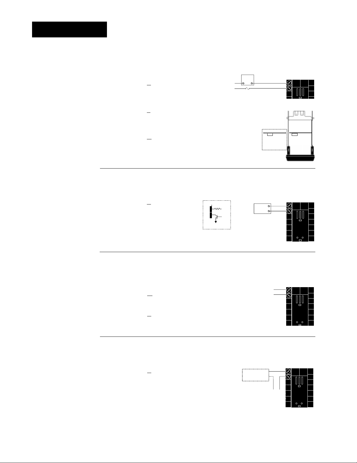
Output 3 Wiring
NOTE:
Successful installation requires five
steps:
• Model number and
software choice
(Appendix);
• DIP switch settings (Chapter 1);
• Sensor match
(Chapter 2 and
Appendix);
• Sensor installation
(Chapter 2); and
• Wiring (Chapter 2).
NOTE:
Switching inductive
loads (relay coils,
solenoids, etc.) with
the mechanical
relay or solid state
relay output options
requires using an
R.C. suppressor.
Watlow carries the
R.C. suppressor
Quencharc brand
name, which is a
trademark of ITW
Paktron. Watlow
Part No. 0804-0147-
0000.
NOTE:
Input-to-output isolation is defeated
when the external
signal conditioner
power supply is
used to power a
transmitter connected to input 1 or
input 2.
Figure 2.14a — AC Outputs
Solid-state Relay
with
Contact Suppression
98 _ _ - _ _ _ _ - B _ _ _
0.5 amps, minimum off-state impedance: 20KΩ
Electromechanical Relay
without
Contact Suppression
98 _ _ - _ _ _ _ - J _ _ _ _
Form A or B, 5 amps, off-state impedance: 31MΩ
Solid-state Relay
without
Contact Suppression
98 _ _ - _ _ _ _ - K _ _ _ _
0.5 amps, off-state impedance: 31MΩ
L2
L1
External
Load
COM
Fuse
Form A or B
alarm jumper
settings (98______-J___ only)
NC Form B
or
NO Form A
-
Form B
1
2
Form A
-
Figure 2.14b — Switched DC
98 _ _ - _ _ _ _ - C _ _ _
Minimum load resistance: 500Ω
19 to 32VÎ (dc)
1
790Ω
2
Internal Circuitry
1
Load
+
2
-
+
External
Figure 2.14c — Process Retransmit
0-20mA, 4-20mA, Load impedance: 600Ω max.
98 _ _ - _ _ _ _ - M _ _ _
0-5VÎÎ, 1-5VÎÎ, 0-10V
ÎÎ
(VDC), Load impedance: 500Ω min.
1
+
2
-
98 _ _ - _ _ _ _ - N _ _ _
Figure 2.14d — External Signal Conditioner Power Supply
98 _ _ - _ _ _ _ - T _ _ _
˜
Loop powered
Transmitter
4-20mA out
1
+
+V
2
-
-V
2.14 WATLOW Series 988 User’s Manual
NOTE:
See Chapter 1 for
power supply DIP
switch information.
-
+
Input
1 or 2
Installation and Wiring, Chapter 2
Page 24
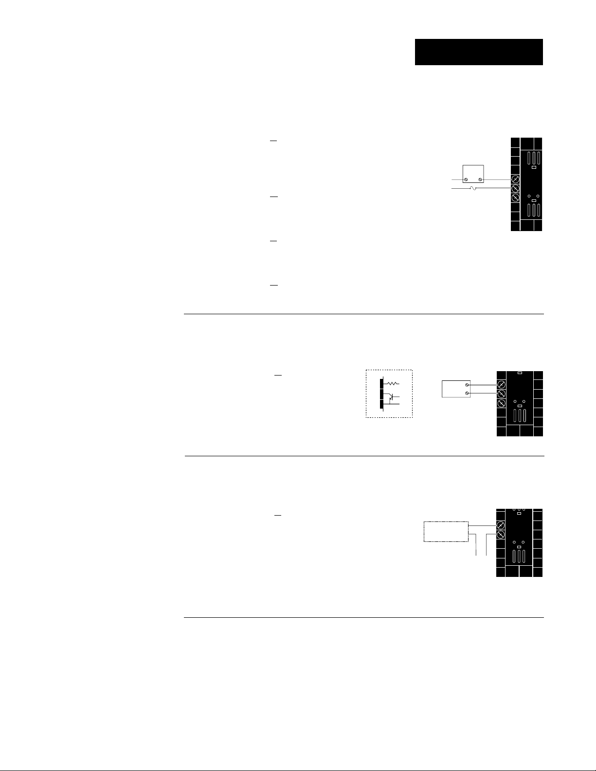
Output 4 Wiring
5
6
+
-
+V
-V
Transmitter
4-20mA out
Input
1 or 2
+
-
NOTE:
Successful installation requires five
steps:
• Model number and
software choice
(Appendix);
• DIP switch settings (Chapter 1);
• Sensor match
(Chapter 2 and
Appendix);
• Sensor installation
(Chapter 2); and
• Wiring (Chapter 2).
NOTE:
Switching inductive
loads (relay coils,
solenoids, etc.) with
the mechanical
relay or solid state
relay output options
requires using an
R.C. suppressor.
Watlow carries the
R.C. suppressor
Quencharc brand
name, which is a
trademark of ITW
Paktron. Watlow
Part No. 0804-0147-
0000.
Figure 2.15a — AC Outputs
Solid-state Relay
with
Contact Suppression
98 _ _ - _ _ _ _ - _ B _ _
0.5 amps, minimum off-state impedance: 20KΩ
Electromechanical Relay
with
Contact Suppression
(Suppression between NO and COM contacts only)
98 _ _ - _ _ _ _ - _ D _ _ _
Form C, 5 amps, minimum off-state impedance: 20KΩ
Electromechanical Relay
without
Contact Suppression
External
Load
L2
L1
Fuse
(#7 for D & E outputs only)
NO
COM
NC
5
6
7
98 _ _ - _ _ _ _ - _ E _ _ _
Form C, 5 amps, off-state impedance: 31MΩ
Solid-state Relay
without
Contact Suppression
98 _ _ - _ _ _ _ - _ K _ _ _
0.5 amps, off-state impedance: 31MΩ
Figure 2.15b — Switched DC, Open Collector
98 _ _ - _ _ _ _ - _ C _ _
Maximum voltage: 42VÎÎ(dc)
Maximum current: 1A
19 to 32VÎ (dc)
5
790Ω
6
7
Internal Circuitry
5
+
External
Load
COM
+
-
6
7
Figure 2.15c — External Signal Conditioner Power Supply
NOTE:
Input-to-output isolation is defeated
when the external
transmitter power
supply is used to
power a signal conditioner connected
to input 1 or input 2.
Installation and Wiring, Chapter 2
98 _ _ - _ _ _ _ - _ T _ _
Loop powered
˜
NOTE:
See Chapter 1 for
power supply DIP
switch information.
Controllers with Output 4 (R, S, or U)
For data communications wiring refer to “
with the Watlow Series 988 Family of Controllers”
manual can be downloaded from Watlow’s website at
www.watlow.com
, Product Techical Information - Controls.
WATLOW Series 988 User’s Manual 2.15
Data Communications
manual. This
Page 25
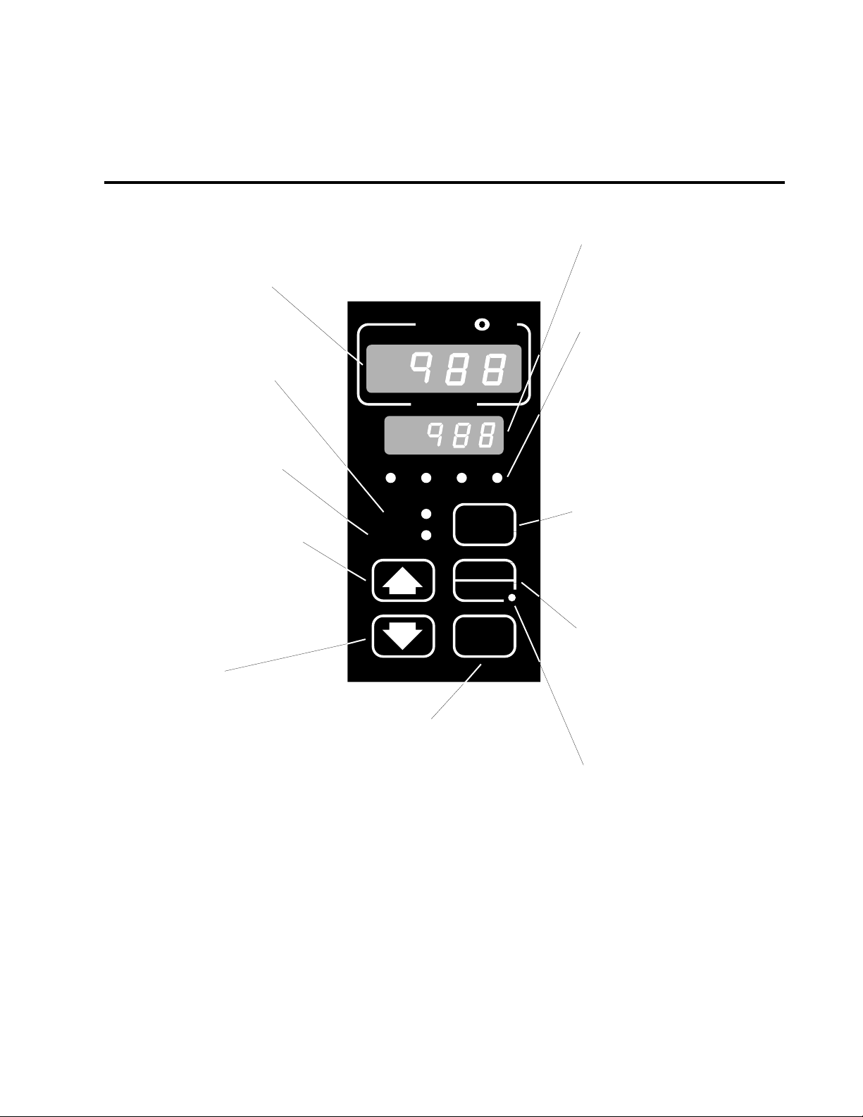
Chapter 3 Front Panel and Display Loop
Keys and Displays
Upper Display
Indicates the actual process value,
prompt parameter value or error
code.
DEV LED
When lit, the lower display shows
the most recent deviation unit from
the set point.
% OUT LED
When lit, the lower display shows
the current percent output.
Up-arrow Key
Increases the value or changes the
parameter in the upper display
(except for set point changes in the
Display Loop, which occur in the
lower display). Hold the key down
to increase the value rapidly. New
data takes effect in five seconds or
when the Mode key or Display key
is pressed.
Down-arrow Key
Decreases the value or changes
the parameter in the upper display
(except for set point changes in the
Display Loop, which occur in the
lower display). Hold the key down
to decrease the value rapidly. New
data takes effect in five seconds or
when the Mode key or Display key
is pressed.
Up + Down Keys
Press simultaneously for three seconds to go to the Setup Menu.
Continue to press both keys for
another three seconds to go to the
Factory Menu. Access to the Setup
and Factory menus can be disabled with lockout DIP switch.
W
TL
W
A
PROCESS
L1 L2 L3 L4
DEV
% OUT
DISPLAY
AUTO
MAN
MODE
SERIES 988
Mode Key
Enters new data and steps to
the next prompt in the current
menu.
Mode + Up-arrow Keys
Hold the Mode key then press
the Up-arrow key to move
backwards through the current menu. Scrolling stops
when you reach the top of the
menu.
Lower Display
Indicates the set point, deviation,
percent power, temperature unit,
menu prompt name or alarm code.
L1, L2, L3, L4
These LED’s indicate when output
1, 2, 3 or 4 are active. Outputs can
be configured as:
Ot1 Control
Ot2 Control or Alarm
Ot3 Alarm or Retransmit
Ot4 Alarm or Communications
(flashes on transmit and
receive)
Display Key
Pressing this key enters the
Display Loop. Press the Display
key at any time to return to this
loop. The next page has more
information on the Display Loop.
Auto/Man Key
In Manual mode the lower display
shows percent output. Pressed
once, it clears any latched alarm. If
pressed again within five seconds
it will toggle between Auto and
Manual mode.
Auto/Man LED
Lit when the control is in Manual
operation. Press the Auto/Man key
twice to enter Automatic operation.
When blinking, press the Auto/Man
key to toggle between Auto and
Manual. After five seconds without
pressing the Auto/Man key, the
LED stops blinking and returns to
its previous state.
Figure 3.1 Series 988 Keys and Displays
Front Panel and Display Loop, Chapter 3
WATLOW Series 988 User’s Manual 3.1
Page 26

Display Loop
˜
NOTE:
For information on
input 1 [`In1] and
input 2 [`In2]
ranges, refer to
Chapter 4.
˜
NOTE:
If [``no] is selected
for [`In2], in the
Input Menu, the
[Pr`2] prompt will
not appear.
Figure 3.2 The Display Loop
Display Loop
The Display Loop is the “home” state of the Series 988 controller. Pressing
the Display key ∂ returns the controller to the Display Loop from any
prompt in any menu. The controller automatically returns to the Display
Loop from any menu when a minute passes without any keys being
pressed.
DISPLAY
DISPLAY
DISPLAY
DISPLAY
DISPLAY
DISPLAY
[`988]
[`988]
[`988]
[`988]
[`988]
current input 1 reading
[`988]
set point 1 (change with Up-arrow > or Down-arrow < key)
current input 2 reading
[Pr`2]
input 2 process (appears only if controller equipped with input 2 hardware)
current input 1 reading
[`988]
deviation from set point, process 1 minus set point 1 (DEV light on)
current input 1 reading
[`100]
percent output (%OUT light on)
current input 1 reading
[``°C]
units selected (units, °F or °C)
3.2 WATLOW Series 988 User’s Manual
Front Panel and Display Loop, Chapter 3
Page 27
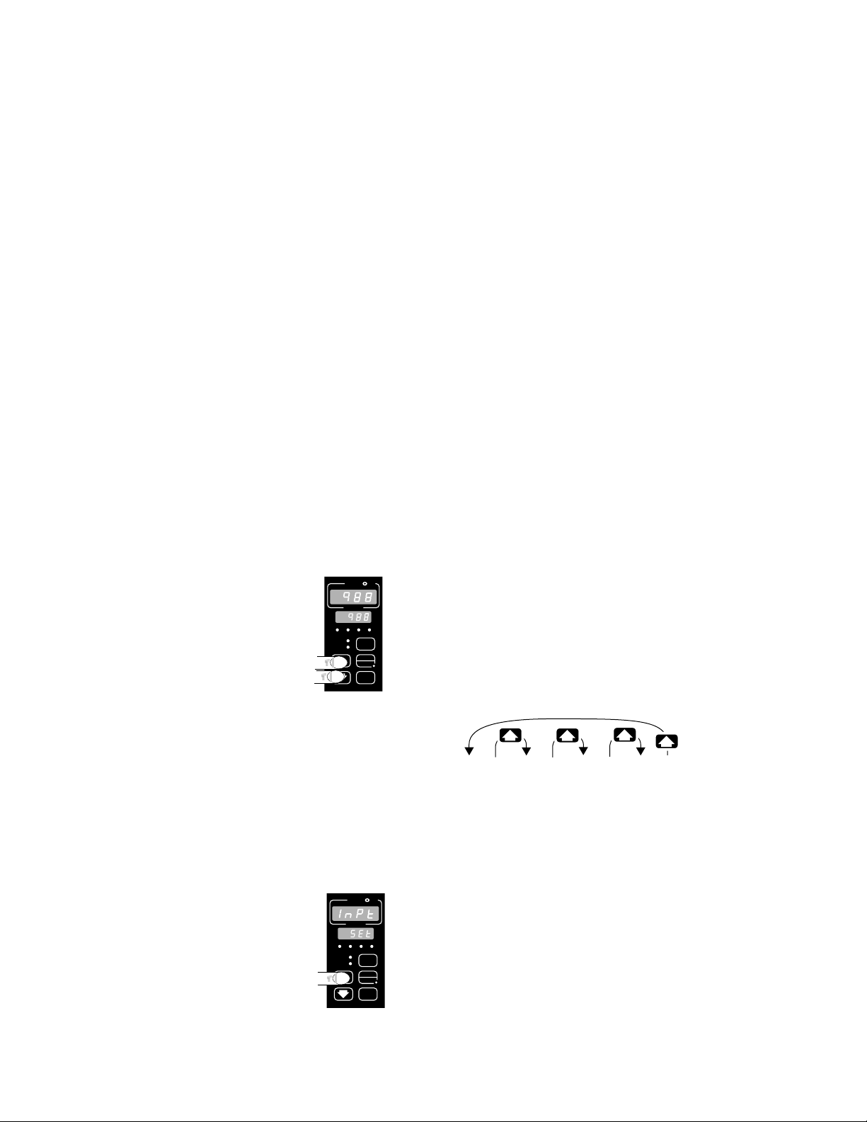
Chapter 4 The Setup Menus
NOTE:
When navigating
through menus,
outputs will be disabled.
˜
NOTE:
Press the Display
key ∂ to return to
the Display Loop
from any point in
any menu.
Navigating the Setup Menus
To reach the Setup Menus, begin in the Display Loop and press both the Uparrow > and Down-arrow < keys for three seconds. The Setup Menu
prompt [`SEt] will appear in the lower display, and the Input Menu prompt
[InPt] will appear in the upper display. The four Setup Menus are: Input
[InPt]; Output [OtPt]; Global [GLbL]; and Communications [COM]. Use the
Up-arrow > or Down-arrow < key to select a menu and the Mode key µ
to step through a menu. The Communications Menu appears only on units
equipped with the data communications option.
You will not see every prompt in any of these menus. The unit’s configuration
and model number determine which prompts appear. After stepping through
each menu, the Series 988 returns to the Setup Menu prompt [`SEt]. Use
the Up-arrow > and Down-arrow < keys to select the next menu, or use
the Mode key µ to advance through the same menu again. To move backwards through the menu hold the Mode key µ down and press the Uparrow key >. Use the Up-arrow > or Down-arrow < key to change the
prompt setting.
Refer to the Appendix for model number options. For information about
communications and the communications prompts, refer to the supplemental manual Data Communications with the Watlow Series 988 Family of
Controllers.
Figure 4.1 Navigating the
Setup Menus.
˜
NOTE:
The lockout DIP
switch hides the
Setup Menus. See
Chapter 1.
W
PROCESS
L1 L2 L3 L4
DEV
% OUT
SERIES 988
PROCESS
L1 L2 L3 L4
DEV
% OUT
SERIES 988
W
TL
A
❶ Begin in the Display Loop, and press the Up-arrow
DISPLAY
AUTO
MAN
MODE
TL
W
A
> and Down-arrow < keys simultaneously to
reach the Setup Menus.
[Inpt]
[`Set]
Input
Menu
p. 4.2
W
[OtPt] [gLbL] [COm]
[`Set] [`Set]
Output
Menu
p. 4.18
Global
Menu
p. 4.34
[`Set]
Communications
Menu
p. 4.44
❷ Press the Up-arrow key > to select one of the
Setup Menus.
DISPLAY
AUTO
MAN
MODE
Setup Menus, Chapter 4
WATLOW Series 988 User’s Manual 4.1
Page 28

Setup-Input
Reaching the Input Menu
W
TL
W
A
PROCESS
L1 L2 L3 L4
DEV
DISPLAY
% OUT
AUTO
MAN
MODE
SERIES 988
❸ Select the Input Menu, then press
the Mode key µ to step through the
prompts.
…
…
[```0] [```1] [```2] [``60]
[Ftr1] [Ftr1] [Ftr1] [Ftr1]
[``no]
[Lin1]
[root]
[Lin1]
❹ Press the Up-arrow key > or the
Down-arrow key < to select one of
the prompt values.
*Prompts may not appear,
depending on controller
configuration.
…
MODE
MODE
MODE
MODE
MODE
MODE
MODE
MODE
MODE
MODE
MODE
MODE
MODE
MODE
MODE
MODE
MODE
MODE
MODE
MODE
MODE
MODE
[Inpt]
[`Set]
[`In1]
[deC1]
[`rL1]
[`rH1]
[CAL1]
[rtd1]
[Ftr1]
[Lin1]
[`ln2]
[`rSp]
[deC2]
[`RL2]
[`RH2]
[LrnL]
[LrnH]
[CAL2]
[rtd2]
[Ftr2]
[Lin2]
[Hunt]
[SHYS]
Setup Prompt
Input 1
*Decimal 1
Range Low 1
Range High 1
Calibration Offset 1
*RTD Calibration Curve 1
Software Filter 1
*Linearization 1
*Input 2
*Remote Set Point
*Decimal 2
*Range Low 2
*Range High 2
*Learn Low
*Learn High
*Calibration Offset 2
*RTD Calibration Curve 2
*Software Filter 2
*Linearization 2
*Hunt
*Slidewire Hysteresis
Enter your settings,
from the controller's
upper display.
Input 1 (p. 4.3)
Input 2 (p. 4.9)
Slidewire (p. 4.16)
Figure 4.2 The Input Menu.
4.2 WATLOW Series 988 User’s Manual
Setup Menus, Chapter 4
Page 29

Input Prompts
O
N
↑
123
O
N
↑
123
Setup-Input
˜
NOTE:
Decimal points may
not always be in the
position specified
below depending on
the the settings in
the Decimal 1
[dEC1] and Decimal
2 [dEC2] parame-
ters in the Input
Menu.
[`In1]
ç
CAUTION:
Changing the value
of [`In1] changes
most other prompts
to the factory
default values.
Document all settings before changing sensor type.
Verify the correct
sensor type before
making a change.
Failure to follow
this guideline could
result in damage to
equipment or property. Document all
settings before
changing sensor
type.
When you are in the Setup menus, the Series 988 displays the menu selection ( [InPt], [OtPt], [GLbL] or [COM] ) in the upper display, and [`SEt] in
the lower display.
The Up-arrow > or Down-arrow key < selects another menu. Press the
Mode key µ to display the prompt in the lower display and its value in the
upper display. Use the Up-arrow > or Down-arrow < key to change the
value in the upper display. The new value will not take effect until after a
five-second delay or until you press the Mode key µ.
Input 1
Select sensor type for input 1. This selection must match the sensor type
connected to terminals 8, 9 and 10. See Appendix for more information
about sensors.
• Changing the value of [`In1] changes all other prompts to the factory
default values, except the Communications and Lockout menus, the
[`C_F] prompt in the Global Menu and the [`dFL] prompt in the
Calibration Menu. If you change the value, the default warning [dFLt]
will flash in the upper display.
• Changes do not take effect automatically after five seconds; you must
press the Mode key µ to enter the sensor type change and advance to
the next prompt.
[`In1] This prompt always appears.
If Default
↓ ↓
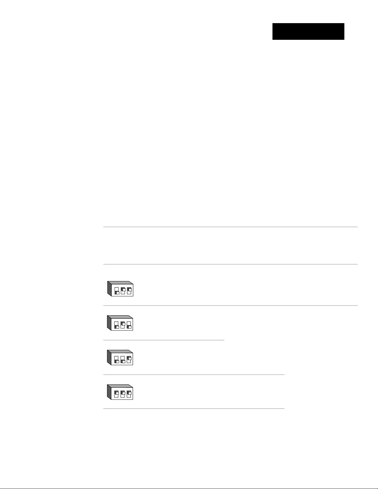
98_ _-1_ _ _-_ _ _ _
no DIP J K T N E W5 W3 Pt2 0-50mV
thermocouple [`In1] [`In1] [`In1] [`In1] [`In1] [`In1] [`In1] [`In1] [`In1]
only
98_ _-2_ _ _-_ _ _ _
Input 1 DIP J K T N E W5 W3 Pt2 0-50mV
thermocouple
[```J] [```H] [```t] [```n] [```E] [```C] [```d] [`Pt2] [0-50]
[```J] [```H] [```t] [```n] [```E] [```C] [```d] [`Pt2] [0-50]
[`In1] [`In1] [`In1] [`In1] [`In1] [`In1] [`In1] [`In1] [`In1]
[`In1]
Input 1 continued
on next page.
Setup Menus, Chapter 4
Input 1 DIP RSB
[```r] [```S] [```b]
[`In1] [`In1] [`In1]
thermocouple
WATLOW Series 988 User’s Manual 4.3
Page 30
Setup-Input
O
N
↑
123
O
N
↑
123
[`In1]
Input 1 continued
from previous
page.
[dEC1]
If Default
↓↓
Input 1 DIP RTD RTD(0.1°)
[`rtd] [`r†d]
[`In1] [`In1]
RTD
Input 1 DIP 4-20mA 0-20mA 0-5VÎ 1-5VÎ 0-10VÎ (dc)
[4-20] [0-20] [`0-5] [`1-5] [0-10]
[`In1] [`In1] [`In1] [`In1] [`In1]
process
Decimal 1
Select the decimal point location for process type input 1 data. This
prompt, in conjunction with the Range Low and Range High prompts,
allows you to format and limit units of measure for process 1.
• All prompts with units of measure related to input 1 will display in the
selected decimal format.
• This affects propbands, alarm set points, process set points, calibration
offsets, deadbands and ranges.
[dEC1] This prompt appears only if you have set input 1 [`In1] to a
process input or to a thermocouple input set to 0-50mV.
Default
↓
[```)] [``)0] [`)00] [)000]
[dEC1] [DEC1] [dEC1] [dEC1]
4.4 WATLOW Series 988 User’s Manual
Setup Menus, Chapter 4
Page 31

Setup-Input
[`rL1]
[`rH1]
˜
NOTE:
These values do not
affect the low or the
high set point limit
for process alarms.
Range Low 1 and Range High 1
Select the low and high limits for input 1. These prompts limit the
adjustment range for the set points. The default values are the same as
the limits of the sensor you selected by setting the input 1 DIP switch and
selecting a value for Input 1 [`In1].
• Process inputs are scaled by these values. Range high is the value displayed when the maximum process signal is present at the input. Range
low is the value displayed when the minimum process signal is present
at the input.
Example: Set [`In1] to [4-20]mA.
Set [`rL1] to [`100].
Set [`rH1] to [`500].
A 4mA input will display [`100].
A 12mA input will display [`300].
A 20mA input will display [`500].
• The low and high values of each sensor type are listed on the specifications page of the Appendix.
• Choose between Fahrenheit and Celsius at the [`C_F] prompt in the
Global Menu.
˜
NOTE:
When high impedance [0-50] is
selected for input 1
the range high for
both [``°C] and
[``°F] can be
extended to
[9999]. The range
low when [``°C] is
selected can be
extended to
[-999].
[`rL1]
[`rH1]
Range Low 1 and
Range High 1
continued on next
page.
[`rL1] [`rH1] These prompts always appear.
Default Default Default Default
↓↓ ↓↓
[``°F] [``°C]
[`rL1] [`rH1] [`rL1] [`rH1]
[```J] [``32]…[1500] [```0]…[`816] 98_ _-1_ _-_ _ _ or
[``in] [`rL1] [`rH1] [`rL1] [`rH1] 98_ _-2_ _-_ _ _
(K)
[```H] [-328]…[2500] [-200]…[1371]
[```t] [-328]…[`750] [-200]…[`399]
[```n] [``32]…[2372] [```0]…[1300]
[```E] [-328]…[1470] [-200]…[`799]
(W5)
[```C] [``32]…[4200] [```0]…[2316]
(W3)
[```d] [``32]…[4200] [```0]…[2316]
[`Pt2] [``32]…[2543] [```0]…[1395]
high impedance
[0-50] [-999]…[`999] [-573]…[`573]
Setup Menus, Chapter 4
WATLOW Series 988 User’s Manual 4.5
Page 32

Setup-Input
[`rL1]
[`rH1]
Range Low 1 and
Range High 1
continued from
previous page.
˜
NOTE:
These values do not
affect the low or the
high set point limit
for process alarms.
[``°F] [``°C]
[`rL1] [`rH1] [`rL1] [`rH1]
[```r] [``32]…[3200] [```0]…[1760] 98_ _-2_ _-_ _ _
only
[`in1]
[```S] [``32]…[3200] [```0]…[1760]
[```b] [``32]…[3300] [```0]…[1816]
[`rtd] [-328]…[1472] [-200]…[`800]
[`r†d] [-9(9]…[99(9] [-7#3]…[53&7]
[4-20] [-999]…[9999] units
[0-20] [-999]…[9999] units
[`0-5] [-999]…[9999] units
[`1-5] [-999]…[9999] units
[0-10] [-999]…[9999] units
[CAL1]
Calibration Offset 1
Offset the input 1 signal by a positive or negative value. This allows you
to compensate for lead resistance, sensor errors or other factors.
[CAL1] This prompt always appears.
If Default
↓↓
[``°F] [-999] … [```0] … [9999]
[`C_F] [CAL1] [CAL1] [CAL1]
(Global Menu)
[``°F]
[`C_F] [`In1] [CAL1] [CAL1] [CAL1]
(Global Menu) (Input Menu)
[``°C] [-999] … [```0] … [9999]
[`C_F] [CAL1] [CAL1] [CAL1]
(Global Menu)
[``°C]
[`C_F] [`In1] [CAL1] [CAL1] [CAL1]
(Global Menu) (Input Menu)
a process input
is selected
[`r†d] [-9(9] … [``)0] … [`9(9]
&
[`r†d] [-5%5] … [``)0] … [`5%5]
&
[-999] … [```0] … [`999]
[CAL1] [CAL1] [CAL1]
units
4.6 WATLOW Series 988 User’s Manual
Setup Menus, Chapter 4
Page 33

Setup-Input
[rtd1]
[Ftr1]
RTD (100Ω) Calibration Curve 1
Select the calibration curve for the RTD 1 input. The RTD input uses
either the European (DIN, 0.003850Ω/Ω/°C) or the Japanese (JIS,
0.003916Ω/Ω/°C) linearization standard.
[rtd1] This prompt appears only if you have set [`In1] to [`rtd] or
[`r†d].
Default
↓
[`din] … [`JIS]
[rtd1] [rtd1]
Software Filter 1
Select the filter time constant, in seconds, for input 1. This smooths a
rapidly changing input signal for display or control purposes.
• Select a positive value to filter only the display.
• Select a negative value to filter the input signal.
• Set the value to [```0] to disable the filter.
[Ftr1] This prompt always appears.
Default
↓
[`-60] … [```0] … [``60]
[Ftr1] [Ftr1] [Ftr1]
Setup Menus, Chapter 4
WATLOW Series 988 User’s Manual 4.7
Page 34

Setup-Input
[Lin1]
˜
NOTE:
See Chapter 8 for
more information
on input linearization.
Linearization 1
Select square root linearization for input 1.
[Lin1] This prompt appears only if you have set [`In1] to a process input
or to a thermocouple set to [0-50]mV.
Default
↓
[``no] [root]
[Lin1] [Lin1]
4.8 WATLOW Series 988 User’s Manual
Setup Menus, Chapter 4
Page 35
Setup-Input
O
N
↑
123
O
N
↑
123
O
N
↑
123
O
N
↑
123
[`In2]
CAUTION:
Changing the value
of [`In2] changes
most other prompts
to the factory
default values.
Document all settings before changing sensor type.
Verify the correct
sensor type before
making a change.
Failure to follow
this guideline could
result in damage to
equipment or property. Document all
settings before
changing sensor
type.
˜
NOTE:
If [``no] is selected
for [`In2] none of
the other input 2
prompts will
appear.
[`In2]
Input 2 continued
on next page.
Input 2
Select sensor type for input 2. This selection must match the sensor
type connected to terminals 18, 19 and 20. See Appendix for more information about sensors.
• Changing the value of [`In2] changes all other prompts to the factory default values, except the Communications and Lockout menus,
the [`C_F] prompt in the Global Menu and the [`dFL] prompt in the
Calibration Menu. If you change the value, the default warning
[dFLt] will flash in the upper display.
• Changes do not take effect automatically after five seconds; you must
press the Mode key µ to enter the sensor type change and advance to
the next prompt.
[`In2] This prompt and other Input 2 prompts appear only on controllers
equipped with input 2 hardware (not 98_ _-_0_ _-_ _ _ _).
If Default
↓ ↓
98_ _-1_ _ _-_ _ _ _
no DIP J K T N E W5 W3 Pt2 0-50mV
[``no] [```J] [```H] [```t] [```n] [```E] [```C] [```d] [`Pt2] [0-50]
thermocouple [``In2] [`In2] [`In2] [`In2] [`In2] [`In2] [`In2] [`In2] [`In2] [`In2]
only
98_ _-2_ _ _-_ _ _ _
Input 2 DIP J K T N E W5 W3 Pt2 0-50mV
[``no] [```J] [```H] [```t] [```n] [```E] [```C] [```d] [`Pt2] [0-50]
[`In2] [`In2] [`In2] [`In2] [`In2] [`In2] [`In2] [`In2] [`In2] [`In2]
thermocouple
Input 2 DIP
[``no] [```r] [```S] [```b]
[`In2] [`In2] [`In2] [`In2]
thermocouple
Input 2 DIP RTD RTD (0.1°)
[``no] [`rtd] [`r†d]
[`In2] [`In2] [`In2]
RTD
Input 2 DIP 4-20mA 0-20mA 0-5VÎ 1-5VÎ 0-10VÎ (dc)
[``no] [4-20] [0-20] [`0-5] [`1-5] [0-10]
[`In2] [`In2] [`In2] [`In2] [`In2] [`In2]
process
RSB
Setup Menus, Chapter 4
WATLOW Series 988 User’s Manual 4.9
Page 36

Setup-Input
[`In2]
Input 2 continued
from previous
page.
[`rSP]
If Default
↓ ↓
98_ _-3_ _ _-_ _ _ _
no DIP slidewire potentiometer
resistance [``In2] [`In2] [`In2]
only
[``no] [SLid] [`POt]
98_ _-4_ _ _-_ _ _ _
no DIP current
current
transformer [``In2] [`In2]
only
[``no] [SLid]
98_ _-5_ _ _-_ _ _ _
no DIP event 2
digital event [``In2] [`In2]
only
[``no] [`Ei2]
Remote Set Point
Enable a remote set point signal.
[`rSP] This prompt appears only if the controller is equipped with input 2
hardware and if [`In2] is not set to [``no] and if [CntL] (in the Global
Menu) is set to [`nor].
Default
↓
[`OFF] [``On]
[`rSP] [`rSP]
4.10 WATLOW Series 988 User’s Manual
Setup Menus, Chapter 4
Page 37

Setup-Input
[dEC2]
[`rL2]
Decimal 2
Select the decimal point location for process type input 2 data. This
prompt, in conjunction with the Range Low and Range High prompts,
allows you to format and limit units of measure for process 2.
• All prompts with units of measure related to input 2 will display in the
selected decimal format.
• This affects propbands, alarm set points, process set points, calibration
offsets, deadbands and ranges.
[dEC2] This prompt appears only if you have set input 2 [`In2] to a
process input, [Curr] or a thermocouple input set to [0-50] mV.
Default
↓
[```)] [``)0] [`)00} [)000]
[dEC2] [dEC2] [dEC2] [dEC2]
Range Low 2 and Range High 2
[`rH2]
[`rL2]
[`rH2]
Range Low 2 and
Range High 2
continued on next
page.
Select the low and high limits for input 2. These prompts limit the
adjustment range for the set points. The default values are the same as
the limits of the sensor you selected by setting the input 2 DIP switch and
selecting a value for Input 2 [`In2].
• Process inputs are scaled by these values. Range high is the value displayed when the maximum process signal is present at the input. Range
low is the value displayed when the minimum process signal is present
at the input.
Example: Set [`In2] to [4-20]mA.
Set [`rL2] to [`100].
Set [`rH2] to [`500].
A 4mA input will display [`100].
A 12mA input will display [`300].
A 20mA input will display [`500].
• The low and high values of each sensor type are listed on the specifications page of the Appendix.
• Choose between Fahrenheit and Celsius at the [`C_F] prompt in the
Global Menu.
[`rL2] [`rH2] These prompts appear only if the controller is equipped
with input 2 hardware and with Input 2 [`In2] not set to [``no] or
[`Ei2].
Setup Menus, Chapter 4
WATLOW Series 988 User’s Manual 4.11
Page 38

Setup-Input
[`rL2]
[`rH2]
Range Low 2 and
Range High 2 continued from previous page.
˜
NOTE:
These values do not
affect the low or the
high set point limit
for process alarms.
˜
Default Default Default Default
↓↓ ↓↓
[``°F] [``°C]
[`rL2] [`rH2] [`rL2] [`rH2]
[```J] [``32]…[1500] [```0]…[`816] 98_ _-1_ _-_ _ _ or
[`in2] [`rL2] [`rH2] [`rL2] [`rH2] 98_ _-2_ _-_ _ _
(K)
[```H] [-328]…[2500] [-200]…[1371]
[```t] [-328]…[`750] [-200]…[`399]
[```n] [``32]…[2372] [```0]…[1300]
[```E] [-328]…[1470] [-200]…[`799]
(W5)
[```C] [``32]…[4200] [```0]…[2316]
(W3)
[```d] [``32]…[4200] [```0]…[2316]
[`Pt2] [``32]…[2543] [```0]…[1395]
high impedance
[0-50] [-999]…[`999] [-573]…[`573]
[```r] [``32]…[3200] [```0]…[1760] 98_ _-2_ _-_ _ _ only
[```S] [``32]…[3200] [```0]…[1760]
NOTE:
When high impedance [0-50] is
selected for input 1
the range high for
both [``°C] and
[``°F] can be
extended to
The range low when
[``°C] is selected
can be extended to
[-999].
[9999].
[```b] [``32]…[3300] [```0]…[1816]
[`rtd] [-328]…[1472] [-200]…[`800]
[`r†d] [-9(9]…[99(9] [-7#3]…[53&7]
[4-20] [-999]…[9999] units
[0-20] [-999]…[9999] units
[`0-5] [-999]…[9999] units
[`1-5] [-999]…[9999] units
[0-10] [-999]…[9999] units
[0-50] [-999]…[9999] units
[0=00] [-999]…[9999] units
slidewire
[SLid] [`100]…[1200] ohms
current
[Curr] [```0]…[``50] amps
potentiometer
[`POt] [```0]…[1200] ohms
4.12 WATLOW Series 988 User’s Manual
Setup Menus, Chapter 4
Page 39

Setup-Input
[LrnL]
˜
NOTE:
See Chapter 8 for
more information
on slidewire feedback.
[LrnH]
˜
NOTE:
See Chapter 8 for
more information
on slidewire feedback.
Learn Low
Write the low-end resistance of the slidewire potentiometer to the
range low 2 parameter.
[LrnL] This prompt appears only on controllers equipped with input 2
hardware and with Input 2 [`In2] set to [SLid] or [`POt].
Default
↓
[``no] [`YES]
[LrnL] [LrnL]
Learn High
Write the high-end resistance of the slidewire potentiometer to the
range low 2 parameter.
[LrnH] This prompt appears only on controllers equipped with input 2
hardware and with Input 2 [`In2] set to [SLid] or [`POt].
Default
↓
[``no] [`YES]
[LrnH] [LrnH]
Setup Menus, Chapter 4
WATLOW Series 988 User’s Manual 4.13
Page 40

Setup-Input
[CAL2]
Calibration Offset 2
Offset the input 2 signal by a positive or negative value. This allows
you to compensate for lead resistance, sensor errors or other factors.
[CAL2] This prompt appears only if the controller is equipped with input 2
hardware and if [`In2] is not set to [``no] or [`Ei2].
If Minimum Default Max. setting/range
↓↓
[``°F] [-999] … [```0] … [`999]
[`C_F] [CAL2] [CAL2] [CAL2]
(Global Menu)
[``°F]
[`C_F] [`In2] [CAL2] [CAL2] [CAL2]
(Global Menu) (Input Menu)
[``°C] [-555] … [```0] … [`555]
[`C_F] [CAL2] [CAL2] [CAL2]
(Global Menu)
[``°C]
[`C_F] [`In2] [CAL2] [CAL2] [CAL2]
(Global Menu) (Input Menu)
a process input
is selected
[`r†d] [-9(9] … [``)0] … [`9(9]
&
[`r†d] [-5%5] … [``)0] … [`5%5]
&
[-999] … [```0] … [`999]
[CAL2] [CAL2] [CAL2]
units
[rtd2]
4.14 WATLOW Series 988 User’s Manual
RTD Calibration Curve 2
Select the calibration curve for the RTD 2 input. The RTD input uses
either the European (DIN, 0.003850Ω/Ω/°C) or Japanese (JIS,
0.003916Ω/Ω/°C) linearization standard.
[rtd2] This prompt appears only on controllers equipped with input 2
hardware and with [`In2] set to [`rtd] or [`r†d].
Default
↓
[`din] [`JIS]
[rtd2] [rtd2]
Setup Menus, Chapter 4
Page 41

Setup-Input
[Ftr2]
[Lin2]
Software Filter 2
Select the filter time constant, in seconds, for input 2. This smooths a
rapidly changing input signal for display or control purposes.
• Select a positive value to filter only the display.
• Select a negative value to filter the input signal.
• Set the value to [```0] to disable the filter.
[Ftr2] This prompt appears only on controllers equipped with input 2
hardware and with [`In2] not set to [``no] or [`Ei2].
Default
↓
[`-60] … [```0] … [``60]
[Ftr2] [Ftr2] [Ftr2]
Linearization 2
˜
NOTE:
See Chapter 8 for
more information
on input linearization.
Select square root linearization for input 2.
[Lin2] This prompt appears only if you have set Input 2 [`In2] to a
process input or to a thermocouple input set to [0-50] mV.
Default
↓
[``no] [root]
[Lin2] [Lin2]
Setup Menus, Chapter 4
WATLOW Series 988 User’s Manual 4.15
Page 42

Setup-Input
[Hunt]
˜
NOTE:
See Chapter 8 for
more information
on slidewire feedback.
Hunt
Set the deadband, as a percentage of output, to keep the valve from
hunting.
• The slidewire hysteresis [SHYS] setting provides additional control over a
valve.
[Hunt] This prompt appears only if the controller is equipped with slidewire
hardware (98_ _-_3_ _-_ _ _) and with [`In2] set to [SLid].
Default
↓
[``)3] … [``!0] … [10)0]
[Hunt] [Hunt] [Hunt]
4.16 WATLOW Series 988 User’s Manual
Setup Menus, Chapter 4
Page 43
Setup-Input
[SHYS]
˜
NOTE:
See Chapter 8 for
more information
on slidewire feedback.
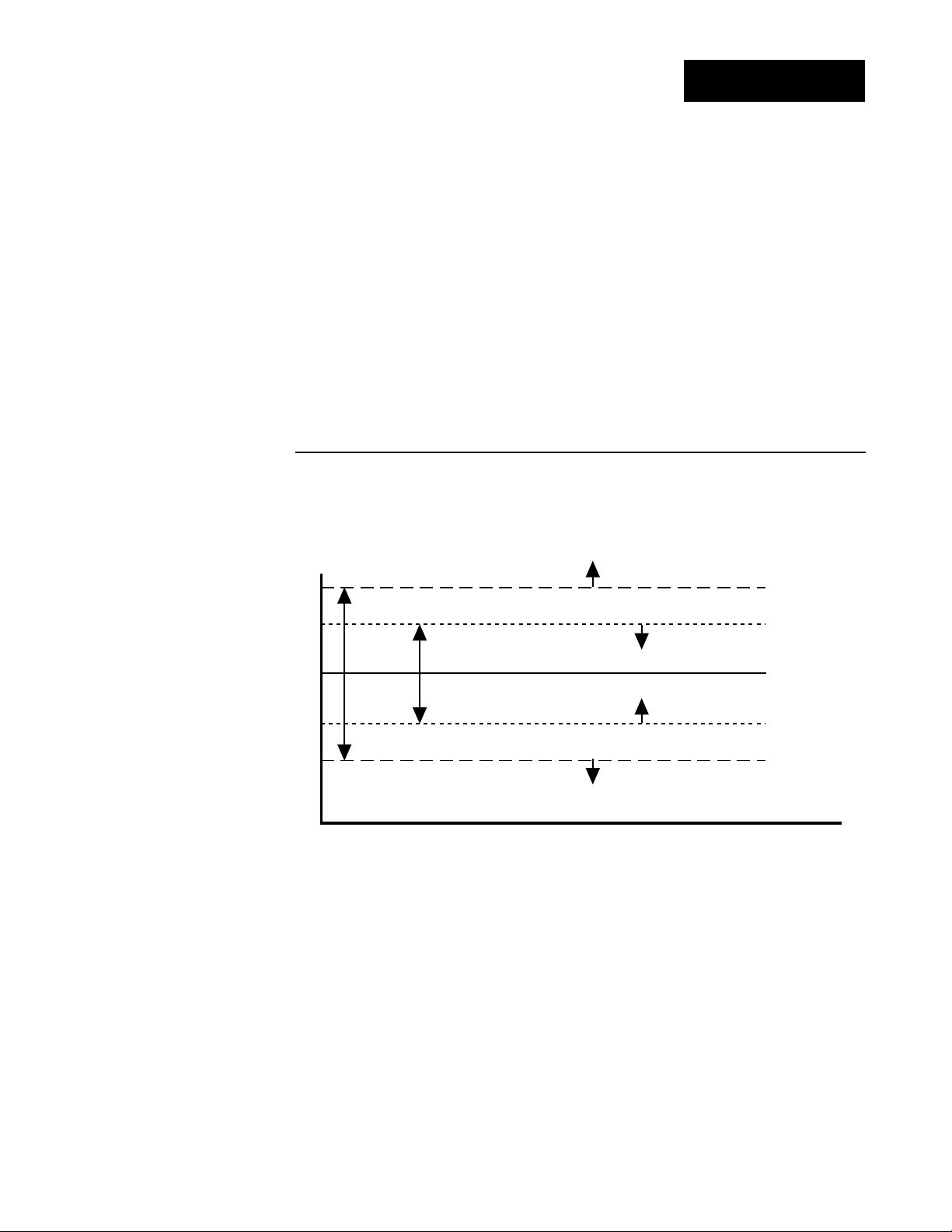
Slidewire Hysteresis
Set the inner hysteresis, the point at which the valve output turns
off.
• The figure below illustrates the interaction between slidewire hysteresis
[SHYS] and hunt [Hunt].
[SHYS] This prompt appears only if the controller is equipped with slidewire
hardware (98_ _-_3_ _-_ _ _ _) and with Input 2 [`In2] set to [SLid]
Default
↓
[```0] [Hunt]
[SHYS] [SHYS]
turn-on point (close)
Figure 4.17 Hunt and slidewire
inner hysteresis.
Hunt
Slidewire
Hysteresis
turn-off point (close)
slidewire position
set point
turn-off point (open)
turn-on point (open)
Setup Menus, Chapter 4
WATLOW Series 988 User’s Manual 4.17
Page 44
Setup-Output
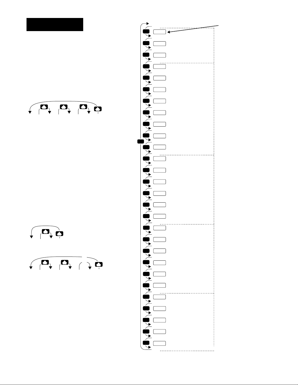
Reaching the Output Menu
❶ Begin in the Display Loop, and
press the Up-arrow > and Downarrow < keys simultaneously for
three seconds to reach the Setup
Menus.
[Inpt]
[`Set]
Input
Menu
p. 4.2
❷ Press the Up-arrow key > to select
one of the Setup Menus.
❸ Press the Mode key µ to step
through the prompts.
[``Ht] [``CL]
[`Ot1] [`Ot1]
[```1]
❹ Press the Up-arrow key > or the
Down-arrow key < to select one of
the prompt values.
Figure 4.18 Navigating the
Output Menu.
[OtPt] [gLbL] [COm]
[`Set] [`Set]
Output
Menu
p. 4.18
[```2]
[Hys2][Hys2]
Global
Menu
p. 4.34
[```3] [`999]
[Hys2] [Hys2]
*Prompts may not appear,
depending on controller
configuration.
[`Set]
Communications
Menu
p. 4.44
…
…
…
MODE
MODE
MODE
MODE
MODE
MODE
MODE
MODE
MODE
MODE
MODE
MODE
MODE
MODE
MODE
MODE
MODE
MODE
MODE
MODE
MODE
MODE
MODE
MODE
MODE
MODE
MODE
MODE
MODE
[OtPt]
[`set]
[`Ot1]
[Prc1]
[HyS1}
[`Ot2]
[Prc2]
[Hys2]x
[Sp2c]
[`Al2]
[A25d]
[LAt2]
[SIL2]
[`Ot3]
[`Al3]
[A3sd]
[Hys3]
[Lat3]
[SIL3]
[`Ot4]
[`AL4]
[A4Sd}
[HyS4]
[LAt4]
[SIL4}
[Aout]
[Prc3}
[A`rL]
[A`rH]
[ACAL]
Setup Prompt
Output 1
*Process 1
*Hysteresis 1
*Output 2
*Process 2
*Hysteresis 2
*Set Point 2 Control
*Alarm 2
*Alarm 2 Side
*Latching 2
*Silencing 2
*Output 3
*Alarm 3
*Alarm 3 Side
*Hysteresis 3
*Latching 3
*Silencing 3
*Output 4
*Alarm 4
*Alarm 4 Side
*Hysteresis 4
*Latching 4
*Silencing 4
*Analog Output
*Process 3
*Retransmit Low Limit
*Retransmit High Limit
*Retransmit Calibration Offset
Enter your settings,
from the controller's
upper display.
Output 1 (p. 4.19)
Output 2 (p. 4.21)
Output 3 (p. 4.25)
Output 4 (p. 4.28)
Output 3 retransmit
(p. 4.31)
4.18 WATLOW Series 988 User’s Manual
Setup Menus, Chapter 4
Page 45

Setup-Output
˜
NOTE:
Decimal points may
not always be in the
position specified
below depending
on the the settings
in the Decimal 1
[deC1] and Decimal
2 [deC2] parame-
ters in the Input
Menu.
[`Ot1]
Output Prompts
When you are in the Setup menus, the Series 988 displays the menu
selection ( [InPt], [OtPt], [GLbL] or [COM] ) in the upper display, and
[`SEt] in the lower display.
The Up-arrow > or Down-arrow key < selects another menu. Press the
Mode key µ to display the first prompt in the lower display and its value
in the upper display. Use the Up-arrow > and Down-arrow < keys to
change the value in the upper display. The new value will not take effect
until after a five-second delay or until you press the Mode key µ.
Output 1
Set the way that output 1 will respond to a difference between the set
point and an input variable.
• [``Ht] select reverse action, so that output 1 responds when the input
signal is less than the setpoint.
• [``CL] select direct action, so that output 1 responds when the input
signal is more than the setpoint.
[`Ot1] This prompt always appears.
Default
↓
[``Ht] [``CL]
[`Ot1] [`Ot1]
Setup Menus, Chapter 4
WATLOW Series 988 User’s Manual 4.19
Page 46

Setup-Output
[Prc1]
[HYS1]
Process 1
Select the process range for output 1.
[Prc1] This prompt appears only on controllers equipped with output 1
process hardware (98_ _-_ _F_-_ _ _ _).
Default
↓
4-20mA 0-20mA 0-5VÎ 1-5VÎ 0-10VÎ (dc)
[4-20] [0-20] [`0-5] [`1-5] [0-10]
[Prc1] [Prc1] [Prc1] [Prc1] [Prc1]
Hysteresis 1
Select the switching hysteresis for output 1. This determines the
change in temperature or process units needed to turn the output from
full on to full off.
[HYS1] This prompt does not appear on controllers equipped with output 1
process hardware (98_ _-_ _F_-_ _ _ _). This prompt only appears with the
controller set up as an on/off controller ( [PBIA] = [```0] ).
If Default
↓↓
[``°F] [```1] … [```3] … [`999]
[`C_F] [HYS1 ][HYS1] [HYS1]
(Global Menu)
[``°F]
[`C_F] [`In1] [HYS1] [HYS1] [HYS1]
(Global Menu) (Input Menu)
[``°C] [```1] … [```2] … [`555]
[`C_F] [HYS1] [HYS1] [HYS1]
(Global Menu)
[``°C]
[`C_F] [`In1] [HYS1] [HYS1] [HYS1]
(Global Menu) (Input Menu)
a
process input
is selected
[`r†d] [``)1] … [``#0] … [`9(9]
&
[`r†d] [``)1] … [``@0] … [`5%5]
&
[```1] … [```3] … [`999]
[HYS1] [HYS1] [HYS1]
units
4.20 WATLOW Series 988 User’s Manual
Setup Menus, Chapter 4
Page 47

Setup-Output
[`Ot2]
Output 2
Set the way that output 2 will respond to a difference between the set
point and an input variable.
• [`AL2] de-energizes output 2 in an alarm condition.
• [AL2n] energizes output 2 in an alarm condition.
• [``Ht] select reverse action, so that output 2 responds when the input
signal is less than the set point.
• [``CL] select direct action, so that output 2 responds when the input
signal is more than the set point.
[`Ot2] This prompt appears only on controllers equipped with output 2
hardware (not 98_ _-_ _ _A-_ _ _ _). [`AL2] and [AL2n] do not appear if output 2 is a process output (98_ _-_ _ _F-_ _ _ _). [``Ht] and [``CL] do not
appear if [AL90] (in the Global Menu) is set to [dUPL].
Default
↓
[``no] [`AL2] [Al2n] [``Ht] [``CL]
[`Ot2] [`Ot2] [`Ot2] [`Ot2] [`Ot2]
[Prc2]
Setup Menus, Chapter 4
Process 2
Select the process range for output 2.
[Prc2] This prompt appears only on controllers equipped with output 2
process hardware (98_ _-_ _ _F-_ _ _ _) and with [`Ot2] not set to [``no].
Default
↓
4-20mA 0-20mA 0-5VÎ 1-5VÎ 0-10VÎ (dc)
[4-20] [0-20] [`0-5] [`1-5] [0-10]
[Prc2] [Prc2] [Prc2] [Prc2] [Prc2]
WATLOW Series 988 User’s Manual 4.21
Page 48

Setup-Output
[HYS2]
Hysteresis 2
Select the switching hysteresis for output 2. This determines the
change in temperature or process units needed to turn the output from off
to on.
• If [`AL2] is set to [rAtE] settings for [HYS2] will be in degrees per
minute or units per minute.
• If the input referenced by [`AL2] is set to [`r†d] the range is affected as
listed below.
[HYS2] This prompt appears only on controllers equipped with output 2
hardware and with the controller set up as an on/off controller ([Pb2A} =
[```0]), and with [`Ot2] not set to [``no]. This prompt does not appear
on controllers equipped with output 2 process hardware, ([`In2} = [sLid],
or if [ALg0} in the Global menu = [dUPL]).
If Default
↓↓
[``°F] [```1] … [```3] … [`999]
[`C_F] [HYS2] [HYS2] [HYS2]
(Global Menu)
[``°F]
[`C_F]
(Global Menu) (see note above)
[``°C] [```1] … [```2] … [`555]
[`C_F] [HYS2][ HYS2] [HYS2]
(Global Menu)
[``°C]
[`C_F]
(Global Menu) (see note above)
a process input
is selected
[`r†d] [``)1] … [``#0] … [`9(9]
&
Input 1 or 2
[`r†d] [``)1] … [``@0] … [`5%5]
&
Input 1 or 2
[HYS2] [HYS2] [HYS2]
[HYS2] [HYS2] [HYS2]
[```1] … [```3] … [`999]
[HYS2] [HYS2] [HYS2]
units
[SP2c]
4.22 WATLOW Series 988 User’s Manual
Set Point 2 Control
Select a second set point.
• [``Pr] enables a set point independent from the Set Point 1 [`SP1]
value.
• [``dE] enables a set point at a deviation from the Set Point 1 [`SP1]
value.
[Prc1] This prompt appears only if output 2 hardware is present and is
equal to the output 1 setting.
Default
↓
[``Pr] [``dE]
[SPc2] [SPc2]
Setup Menus, Chapter 4
Page 49

Setup-Output
[`AL2]
˜
NOTE:
See Chapter 7 for
more information
on alarms.
Alarm 2
Select the alarm type for alarm 2. Select the trigger points for the alarm
with the [A2LO] and [A2HI] settings in the System Menu [`SYS].
• [`Pr1] uses the process signal from input 1. Changing the set point
does not change the alarm response.
• [`dE1] uses a deviation from the input 1 signal. Changing the set point
changes the alarm response.
• [`Pr2] uses the process signal from input 2. This choice does not appear
if the controller is not equipped with input 2 hardware or if [`In2] is set
to [``no] or [`Ei2].
• [`dE2] uses a deviation from the input 2 signal. This prompt does not
appear if the controller is not equipped with input 2 hardware or if
[`In2] is set to [``no] or [`Ei2].
• [rAtE] uses the rate of change at input 1 in degrees per minute.
[`AL2] This prompt appears only on controllers equipped with output 2
hardware and with [`Ot2] set to [`AL2] or [AL2n].
Default
↓
[`Pr1] [`de1] [`Pr2] [`de2] [rAtE] [``no]
[`AL2] [`AL2] [`AL2] [`AL2] [`AL2] [`AL2]
[A2Sd]
Setup Menus, Chapter 4
Alarm 2 Side
Select what triggers alarm 2.
• [both] triggers an alarm when the signal ≤ [A2LO] or ≥ [A2HI].
• [HigH] triggers an alarm when the signal ≥ [A2HI].
• [LoW] triggers an alarm when the signal ≤ [A2LO].
[A2Sd] This prompt appears only on controllers equipped with output 2
hardware and with [`Ot2] set to [`AL2] or [AL2n].
Default
↓
[both] [HigH] [Low]
[A2Sd] [A2Sd] [A2Sd]
WATLOW Series 988 User’s Manual 4.23
Page 50

Setup-Output
[LAt2]
˜
NOTE:
See Chapter 7 for
more information
on alarms.
[SIL2]
Latching 2
Select whether alarm 2 will be latching or non-latching. A latching
alarm [`LAt] must be turned off manually. A non-latching alarm [`nLA]
turns off when an alarm condition no longer exists.
[LAt2] This prompt appears only on controllers equipped with output 2
hardware and with [`Ot2] set to [`AL2] or [AL2n].
Default
↓
[`nLA] [`LAt]
[LAt2] [LAt2]
Silencing 2
Select silencing to inhibit alarm 2 on startup and to allow the operator to reset the alarm output, not the visual display.
• Silencing disables the alarm until the signal is between [A2LO] and
[A2HI].
[`AL2] This prompt appears only on controllers equipped with output 2
hardware and with [`Ot2] set to [`AL2] or [AL2n].
Default
↓
[`OFF] [``On]
[SIL2] [SIL2]
4.24 WATLOW Series 988 User’s Manual
Setup Menus, Chapter 4
Page 51

Setup-Output
[`Ot3]
˜
NOTE:
See Chapter 7 for
more information
on alarms.
[`AL3]
Output 3
Select the alarm condition for output 3.
• [`AL3] de-energizes output 3 in an alarm condition.
• [AL3n] energizes output 3 in an alarm condition.
[`Ot3] This prompt appears only on controllers equipped with output 3
hardware for a relay (98_ _-_ _ _ _-B_ _ _, 98_ _-_ _ _ _-J_ _ _ or
98_ _-_ _ _ _-K_ _ _) or switched dc (98_ _-_ _ _ _-C_ _ _).
Default
↓
[`AL3] [AL3n] [``no]
[`Ot3] [`Ot3] [`Ot3]
Alarm 3
Select the alarm type for alarm 3.
• [`Pr1] uses the process signal from input 1.
• [`dE1] uses a deviation from the input 1 signal.
• [`Pr2] uses the process signal from input 2. This prompt does not
appear if the controller is not equipped with input 2 hardware or if
[`In2] is set to [``no] or [`Ei2].
• [`dE2] uses a deviation from the input 2 signal. This prompt does not
appear if the controller is not equipped with input 2 hardware or if
[`In2] is set to [``no] or [`Ei2].
• [rAtE] uses the rate of change at input 1 in degrees per minute.
[`AL3] This prompt appears only on controllers equipped with output 3
hardware for a relay (98_ _-_ _ _ _-B_ _ _, 98_ _-_ _ _ _-J_ _ _ or
98_ _-_ _ _ _-K_ _ _) or switched dc (98_ _-_ _ _ _-C_ _ _), and with [`Ot3]
set to [`AL3] or [AL3n].
Default
↓
[`Pr1] [`de1] [`Pr2] [`de2] [rAtE] [``no]
[`AL3] [`AL3] [`AL3] [`AL3] [`AL3] [`AL3]
Setup Menus, Chapter 4
WATLOW Series 988 User’s Manual 4.25
Page 52

Setup-Output
[A3Sd]
˜
NOTE:
See Chapter 7 for
more information
on alarms.
[HYS3]
Alarm 3 Side
Select what triggers alarm 3.
• [both] triggers an alarm when the signal ≤ [A3LO] or ≥ [A3HI].
• [HiGH] triggers an alarm when the signal ≥ [A3HI].
• [LOW] triggers an alarm when the signal ≤ [A3LO].
[A3Sd] This prompt appears only on controllers equipped with output 3
hardware for a relay (98_ _-_ _ _ _-B_ _ _, 98_ _-_ _ _ _-J_ _ _ or
98_ _-_ _ _ _-K_ _ _) or switched dc (98_ _-_ _ _ _-C_ _ _) and with [`Ot3]
set to [`AL3] or [AL3n].
Default
↓
[both] [HiGH] [LOW]
[A3Sd] [A3Sd] [A3Sd]
Hysteresis 3
Select the switching hysteresis for alarm 3. This determines the change
in temperature or process units needed to turn the output from off to on.
• If [`AL3] is set to [rAtE] settings for [HYS3] will be in degrees per
minute or units per minute.
• If the input referenced by [`AL3] is set to [`r†d] the range is affected as
listed below.
[HYS3] This prompt appears only on controllers equipped with output 3
hardware for a relay (98_ _-_ _ _ _-B_ _ _, 98_ _-_ _ _ _-J_ _ _ or
98_ _-_ _ _ _-K_ _ _) or switched dc (98_ _-_ _ _ _-C_ _ _).
If Default
↓↓
[``°F] [```1] … [```3] …[`999]
[`C_F] [HYS3] [HYS3] [HYS3]
(Global Menu)
[``°F]
[`C_F]
(Global Menu) (see note above)
[``°C] [```1] … [```2] …[`555]
[`C_F] [HYS3] [HYS3] [HYS3]
(Global Menu)
[``°C]
[`C_F]
(Global Menu) (see note above)
a process input
is selected
&
[`r†d] [``)1] … [``#0] …[`9(9]
Input 1 or 2
&
[`r†d] [``)1] … [``@0] …[`5%5]
Input 1 or 2
[HYS3] [HYS3] [HYS3]
[HYS3] [HYS3] [HYS3]
[```1] … [```3] …[`999]
[HYS3] [HYS3] [HYS3]
units
4.26 WATLOW Series 988 User’s Manual
Setup Menus, Chapter 4
Page 53

Setup-Output
[LAt3]
˜
NOTE:
See Chapter 7 for
more information
on alarms.
[SIL3]
Latching 3
Select whether alarm 3 will be latching or non-latching. A latching
alarm [`LAt] must be turned off manually. A non-latching alarm [`nLA]
turns off when an alarm condition no longer exists.
[LAt3] This prompt appears only on controllers equipped with output 3
hardware for a relay (98_ _-_ _ _ _-B_ _ _, 98_ _-_ _ _ _-J_ _ _ or
98_ _-_ _ _ _-K_ _ _) or switched dc (98_ _-_ _ _ _-C_ _ _) and with [`Ot3] set
to [`AL3] or [AL3n].
Default
↓
[`nLA] [`LAt]
[LAt3] [LAt3]
Silencing 3
Select silencing to inhibit alarm 3 on startup and to allow the operator to reset the alarm output, not the visual display.
˜
NOTE:
See Chapter 7 for
more information
on alarms.
• Silencing disables the alarm until the signal is between [A3LO] and
[A3HI].
[SIL3] This prompt appears only on controllers equipped with output 3
hardware for a relay (98_ _-_ _ _ _-B_ _ _, 98_ _-_ _ _ _-J_ _ _ or
98_ _-_ _ _ _-K_ _ _) or switched dc (98_ _-_ _ _ _-C_ _ _) and with [`Ot3] set
to [`AL3] or [AL3n].
Default
↓
[`OFF] [``On]
[SIL3] [SIL3]
Setup Menus, Chapter 4
WATLOW Series 988 User’s Manual 4.27
Page 54

Setup-Output
[`Ot4]
˜
NOTE:
See Chapter 7 for
more information
on alarms.
[`AL4]
Output 4
Select the alarm condition for output 4.
• [`AL4] de-energizes output 4 in an alarm condition.
• [AL4n] energizes output 4 in an alarm condition.
[`Ot4] This prompt appears only on controllers equipped with output 4
hardware for a relay (98_ _-_ _ _ _-_B_ _, 98_ _-_ _ _ _-_D_ _ ,
98_ _-_ _ _ _-_E_ _ or 98_ _-_ _ _ _-_K_ _) or switched dc (98_ _-_ _ _ _-_C_ _).
Default
↓
[`AL4] [AL4n]
[`Ot4] [`Ot4]
Alarm 4
Select the alarm type for alarm 4.
• [`Pr1] uses a process signal from input 1.
• [`dE1] uses a deviation from the input 1 signal.
• [`Pr2] uses the process signal from input 2. This prompt does not
appear if the controller is not equipped with input 2 hardware or if
[`In2] is set to [``no] or [`Ei2].
• [`dE2] uses a deviation from the input 2 signal. This prompt does not
appear if the controller is not equipped with input 2 hardware or if
[`In2] is set to [``no] or [`Ei2].
• [rAtE] uses the rate of change at input 1 in degrees per minute.
[`AL4] This prompt appears only on controllers equipped with output 4
hardware for a relay (98_ _-_ _ _ _-_B_ _, 98_ _-_ _ _ _-_D_ _ ,
98_ _-_ _ _ _-_E_ _ or 98_ _-_ _ _ _-_K_ _) or switched dc (98_ _-_ _ _ _-_C_ _).
Default
↓
[`Pr1] [`dE1] [`Pr2] [`dE2] [rAtE] [``no]
[`AL4] [`AL4] [`AL4] [`AL4] [`AL4] [`AL4]
4.28 WATLOW Series 988 User’s Manual
Setup Menus, Chapter 4
Page 55

Setup-Output
[A4Sd]
˜
NOTE:
See Chapter 7 for
more information
on alarms.
Alarm 4 Side
Select what triggers alarm 4.
• [both] triggers an alarm when the signal ≤ [A4LO] or ≥ [A4HI].
• [HiGH] triggers an alarm when the signal ≥ [A4HI].
• [LOW] triggers an alarm when the signal ≤ [A4LO].
[A4Sd] This prompt appears only on controllers equipped with output 4
hardware for a relay (98_ _-_ _ _ _-_B_ _, 98_ _-_ _ _ _-_D_ _ ,
98_ _-_ _ _ _-_E_ _ or 98_ _-_ _ _ _-_K_ _) or switched dc (98_ _-_ _ _ _-_C_ _)
and with [`Ot4] set to [`AL4] or [AL4n].
Default
↓
[BOTH] [HIGH] [LOW]
[A4SD] [A4SD] [A4SD]
Setup Menus, Chapter 4
WATLOW Series 988 User’s Manual 4.29
Page 56

Setup-Output
[HYS4]
Hysteresis 4
Select the switching hysteresis for alarm 4. This determines the change
in temperature or process units needed to turn the output from off to on.
• If [`AL4] is set to [rAtE] settings for [HYS4] will be in degrees per
minute or units per minute.
• If the input referenced by [`AL4] is set to [`r†d] the range is affected as
listed below.
[HYS4] This prompt appears only on controllers equipped with output 4
hardware for a relay (98_ _-_ _ _ _-_B_ _, 98_ _-_ _ _ _-_D_ _ ,
98_ _-_ _ _ _-_E_ _ or 98_ _-_ _ _ _-_K_ _) or switched dc (98_ _-_ _ _ _-_C_ _).
If Default
↓↓
[``°F] [```1] … [```3] … [`999]
[`C_F] [HYS4] [HYS4] [HYS4]
(Global Menu)
[``°F]
[`C_F]
(Global Menu) (see note above)
[``°C] [```1] … [```2] … [`555]
[`C_F] [HYS4] [HYS4] [HYS4]
(Global Menu)
[``°C]
[`C_F]
(Global Menu) (see note above)
a process input
is selected
[`r†d] [``)1] … [``#0] … [`9(9]
&
Input 1 or 2
[`r†d] [``)1] … [``@0] … [`5%5]
&
Input 1 or 2
[HYS4] [HYS4] [HYS4]
[HYS4] [HYS4] [HYS4]
[```1] … [```3] … [`999]
[HYS4] [HYS4] [HYS4]
units
[LAt4]
˜
NOTE:
See Chapter 7 for
more information
on alarms.
4.30 WATLOW Series 988 User’s Manual
Latching 4
Select whether alarm 4 will be latching or non-latching. A latching
alarm [`LAT] must be turned off manually. A non-latching alarm [`nLA]
turns off when an alarm condition no longer exists.
[LAt4] This prompt appears only on controllers equipped with output 4
hardware for a relay (98_ _-_ _ _ _-_B_ _, 98_ _-_ _ _ _-_J_ _ or
98_ _-_ _ _ _-_K_ _) or switched dc (98_ _-_ _ _ _-_C_ _). and with [`Ot4] set
to [`AL4] or [AL4n].
Default
↓
[`nLA] [`LAt]
[LAt4] [LAt4]
Setup Menus, Chapter 4
Page 57

Setup-Output
[SIL4]
˜
NOTE:
See Chapter 7 for
more information
on alarms.
[Aout]
Silencing 4
Select silencing to inhibit alarm 4 on startup and to allow the operator to reset the alarm output, not the visual display.
• Silencing disables the alarm until the signal is between [A4LO] and
[A4HI].
[SIL4] This prompt appears only on controllers equipped with output 4
hardware for a relay (98_ _-_ _ _ _-_B_ _, 98_ _-_ _ _ _-_D_ _ ,
98_ _-_ _ _ _-_E_ _ or 98_ _-_ _ _ _-_K_ _) or switched dc (98_ _-_ _ _ _-_C_ _)
and with [`Ot4] set to [`AL4] or [AL4n].
Default
↓
[`OFF] [``On]
[SIL4] [SIL4]
Analog Output
˜
NOTE:
See Chapter 8 for
more information
on retransmit.
Select which value to retransmit as the output 3 signal.
• [Prc1] retransmits the process 1 value.
• [StPt] retransmits the set point.
• [Prc2] retransmits the process 2 value. This prompt appears only if the
controller is equipped with input 2 hardware and if [`In2] is not set to
[``no] or [`Ei2].
• [``no] turns off retransmit function.
[Aout] This prompt appears only on controllers equipped with retransmit
hardware (98_ _-_ _ _ _-M_ _ _ or 98_ _-_ _ _ _-N_ _ _).
Default
↓
[Prc1] [StPt] [Prc2] [``no]
[Aout] [Aout] [Aout] [Aout]
Setup Menus, Chapter 4
WATLOW Series 988 User’s Manual 4.31
Page 58

Setup-Output
[Prc3]
[A`rL]
˜
NOTE:
See Chapter 8 for
more information
on retransmit.
Process 3
Select the range for the retransmit signal at output 3.
[Prc3] This prompt appears only on controllers equipped with retransmit
hardware (98_ _-_ _ _ _-M_ _ _ or 98_ _-_ _ _ _-N_ _ _) and with [Aout] not
set to [``no].
Default
↓
4-20mA 0-20mA 0-5VÎ 1-5VÎ 0-10VÎ (dc)
[4-20] [0-20] [`0-5] [`1-5] [0-10]
[Prc3] [Prc3] [Prc3] [Prc3] [Prc3]
Retransmit Low Limit
Select the low limit for the retransmit signal at output 3.
• The default value is equal to [`rL1] or [`rL2] (in the Input Menu)
depending on whether [Aout] is set to [Prc1] or [Prc2].
• The decimal precision of [A`rL] is determined by [dEC1] (Input Menu) if
[Aout] is set to [Prc1] or [StPt]; it is determined by [dEC2] if [Aout] is
set to [Prc2].
[A`rL] This prompt appears only on controllers equipped with retransmit
hardware (98_ _-_ _ _ _-M_ _ _ or 98_ _-_ _ _ _-N_ _ _) and with [Aout] not
set to [``no].
[-999] … [A`rH]
[A`rL] [A`rL]
4.32 WATLOW Series 988 User’s Manual
Setup Menus, Chapter 4
Page 59

Setup-Output
[A`rH]
[ACAL]
Retransmit High Limit
Select the high limit for the retransmit signal at output 3.
• The default value is equal to [`rH1] or [`rH2] (in the Input Menu)
depending on whether [Aout] is set to [Prc1] or [Prc2].
• The decimal precision of [ACAL] is determined by [dEC1] (Input Menu) if
[Aout] is set to [Prc1] or [StPt]; it is determined by [dEC2] if [Aout] is
set to [Prc2].
[A`rH] This prompt appears only on controllers equipped with retransmit
hardware (98_ _-_ _ _ _-M_ _ _ or 98_ _-_ _ _ _-N_ _ _) and with [Aout] not
set to [``no].
[A`rL] … [9999]
[A`rH] [A`rH]
Retransmit Calibration Offset
˜
NOTE:
See Chapter 8 for
more information
on retransmit.
Select an offset value for the retransmit signal at output 3.
• The decimal precision of [ACAL] is determined by [dEC1] (Input Menu) if
[Aout] is set to [Prc1] or [StPt]; it is determined by [dEC2] if [Aout] is
set to [Prc2].
[ACAL] This prompt appears only on controllers equipped with retransmit
hardware (98_ _-_ _ _ _-M_ _ _ or 98_ _-_ _ _ _-N_ _ _) and with [Aout] not
set to [``no].
If Default
↓↓
[``°F] [-999] … [```0] … [`999]
[`C_F] [ACAL] [ACAL] [ACAL]
(Global Menu)
[``°C] [-555] … [```0] … [`555]
[`C_F] [ACAL] [ACAL] [ACAL]
(Global Menu)
[-999] … [```0] … [`999]
a process input [ACAL] [ACAL] [ACAL]
is selected
units
Setup Menus, Chapter 4
WATLOW Series 988 User’s Manual 4.33
Page 60
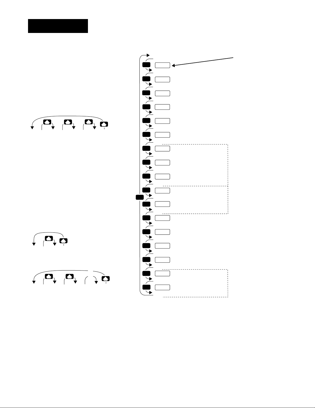
Setup-Global
Reaching the Global Menu
❶ Begin in the Display Loop, and
press the Up-arrow > and Downarrow < keys simultaneously for
three seconds to reach the Setup
Menus.
[Inpt]
[`Set]
Input
Menu
p. 4.2
❷ Press the Up-arrow key > to select
one of the Setup Menus.
❸ Press the Mode key µ to step
through the prompts.
[``°F]
[`C_F]
[```0]
[rate]
[OtPt] [gLbL] [COm]
[`Set] [`Set]
Output
Menu
p. 4.18
Global
Menu
p. 4.34
[`Set]
Communications
Menu
p. 4.44
[``°C]
[`C_F]
…
…
[```1] [```2] [9999]
[rate]
[rate]
…
[rate]
MODE
MODE
MODE
MODE
MODE
MODE
MODE
MODE
MODE
MODE
MODE
MODE
MODE
MODE
MODE
MODE
MODE
MODE
[GlbL]
[`Set]
[`C_F]
[FaIL]
[`Err]
[CntL]
[CSAC]
[ALGO]
[Pid2]
[Proc]
[StPt]
[`EiI]
[`Ei2]
[Anun]
[`LoP]
[`HiP]
[AtSp]
[``rP]
[Rate]
Setup prompt
*Celsius-Fahrenheit
Failure Mode
Error Latching
*Control Type
*Cascade Action
*Algorithm
*PID 2 Crossover Selection
*Crossover Process Value
*Crossover Set Point Value
Event Input 1
*Event Input 2
Annunciator
Low Power Limit
High Power Limit
Auto-tune Set Point
*Ramping Function
*Ramp Rate
Enter your settings,
from the controller's
upper display.
PID (p. 4.38)
Event Input (p. 4.40)
Ramping (p. 4.43)
❹ Press the Up-arrow key > or the
Down-arrow key < to select one of
the prompt values.
Figure 4.34 Navigating the
Global Menu.
4.34 WATLOW Series 988 User’s Manual
*Prompts may not appear, depending
on controller configuration.
Setup Menus, Chapter 4
Page 61

Setup-Global
˜
NOTE:
Decimal points may
not always be in the
position specified
below depending on
the the settings in
the Decimal 1
[dEC1] and Decimal
2 [dEC2] parame-
ters in the Input
Menu.
[`C_F]
Global Prompts
When you are in the Setup menus, the Series 988 displays the menu
selection ([InPt], [OtPt], [GLbL] or [COM]) in the upper display, and
[`SEt] in the lower display.
The Up-arrow > or Down-arrow key < selects another menu. Press
the Mode key µ to display the first prompt in the lower display and its
value in the upper display. Use the Up-arrow > and Down-arrow <
keys to change the value in the upper display. The new value will not take
effect until after a five-second delay or until you press the Mode key µ.
Celsius-Fahrenheit
Select which temperature scale the controller will use.
[`C_F] This prompt appears only on controllers with either Input 1 or
Input 2 set to something other than a process input.
Default
↓
[``°F] [``°C]
[`C_F] [`C_F]
[FAIL]
Failure Mode
Select the output level that the controller will maintain if an input
fails.
• Bumpless transfer [bPLS] maintains the same output settings after an
input failure.
[FAIL] This prompt always appears.
If Default
↓↓
a heat/cool
application
a heat-only
application
a cool-only
application
[bPLS] [-100] … [`100]
[FAIL] [FAIL] [FAIL]
[bPLS] [```0] … [`100]
[FAIL] [FAIL] [FAIL]
[bPLS] [-100] … [```0]
[FAIL] [FAIL] [FAIL]
%
%
%
Setup Menus, Chapter 4
WATLOW Series 988 User’s Manual 4.35
Page 62

Setup-Global
[`Err]
[CntL]
Error Latching
Select whether errors will be latching or non-latching.
• Non-latching alarms [`nLA] turn off when there is no alarm condition.
• Latching alarms [`LAt] must be turned off manually.
[`Err] This prompt always appears.
Default
↓
[`nLA] [`LAt]
[`Err] [`Err]
Control Type
Select a control method: normal [`nor]; cascade [CSCd]; ratio [rAti];
or differential [diFF].
[CntL] This prompt appears only on controllers equipped with enhanced
software (98_B-_ _ _ _-_ _ _ _) and input 2 hardware for a basic thermocouple signal conditioner (98_ _-_1_ _-_ _ _ _) or a universal signal conditioner
(98_ _-_2_ _-_ _ _ _) and with [`rSP] set to [`OFF].
Default
↓
[`nor] [CSCd] [rAti] [diFF]
[CntL] [CntL] [CntL] [CntL]
4.36 WATLOW Series 988 User’s Manual
Setup Menus, Chapter 4
Page 63

Setup-Global
[CSAC]
Cascade Action
Select the control action between the inner and outer loop of a cascade system.
• Direct action [`dir] makes the percent output from the outer loop
directly proportional to the set point of the inner loop (input 2). A 100%
signal in the outer loop will set the inner loop to range high 2 [`rH2]
(Input Menu). A 0% signal in the outer loop will set the inner loop to
range low 2 [`rL2] (Input Menu).
• Reverse action [`rEU] makes the percent output from the outer loop
inversely proportional to the set point of the inner loop (input 2). A 100%
signal in the outer loop will set the inner loop to range low 2 [`rL2]
(Input Menu). A 0% signal in the outer loop will set the inner loop to
range high 2 [`rH2] (Input Menu).
[CSAC] This prompt appears only on controllers equipped with enhanced
software (98_B-_ _ _ _-_ _ _ _) and with [CntL] set to [CSCd].
Default
↓
[`dir] [`rEU]
[CASC] [CASC]
Setup Menus, Chapter 4
WATLOW Series 988 User’s Manual 4.37
Page 64

Setup-Global
[ALGO]
Algorithm
Select the control algorithm.
• [`Pid] selects one set of PID prompts.
• [`Pdr] selects proportional/derivative control with manual reset in per-
cent power.
• [Pid2] selects two complete sets of PID prompts. This selection does not
appear if [CntL] is set to [CSCd].
• [dUPL] selects duplex (heating and cooling) control. This prompt does
not appear unless output 1 is a process output.
[ALGO] This prompt appears only on controllers equipped with enhanced
software (98_B-_ _ _ _-_ _ _ _).
Default
↓
[`Pid] [`Pdr] [Pid2] [dUPL]
[ALGO] [ALGO] [ALGO] [ALGO]
[Pid2]
PID 2 Crossover Selection
Select which parameter determines the crossover from PID A to PID
B: process [Proc]; set point [StPt]; or none [``no].
[Pid2] This prompt appears only on controllers with [ALGO] set to [Pid2].
Default
↓
[Proc] [StPt] [``no]
[Pid2] [Pid2] [Pid2]
4.38 WATLOW Series 988 User’s Manual
Setup Menus, Chapter 4
Page 65

Setup-Global
[Proc]
[StPt]
Crossover Process Value
Select the process value at which the control algorithm will crossover
between PID A and PID B. PID A is active below this value and PID B is
active above this value.
• This value cannot be set lower than range low 1 [`rL1] or higher than
range high 1 [`rH1].
[Proc] This prompt appears only on controllers with [Pid2] set to [Proc].
Default
↓
[`rL1] [`rH1]
[Proc] [Proc]
Crossover Set Point Value
Select the set point value at which the control algorithm will
crossover between PID A and PID B. PID A is active below this value and
PID B is active above this value.
• This value cannot be set lower than range low 1 [`rL1] or higher than
range high 1 [`rH1].
[StPt] This prompt appears only on controllers with [Pid2] set to [StPt].
Default
↓
[`rL1] [`rH1]
[StPt] [StPt]
Setup Menus, Chapter 4
WATLOW Series 988 User’s Manual 4.39
Page 66

Setup-Global
[`Ei1]
Event Input 1
Select the effect of closing the event input 1 switch.
• [``no] disables event input 1.
• [`LOC] locks out the front panel keys.
• [`ALr] resets an alarm.
• [A-M] switches the controller to manual mode at the power level set at
[FAIL] (Global Menu) and disables the Auto/Man åkey.
• [`OFF] turns all control outputs off (de-energize relays).
• [`Pid] switches from PID A to PID B.
• [Actn] selects the opposite control action for output 1 and 2.
• [`rSP] switches to a remote set point.
• [IdSP] switches to an idle or second set point.
[`Ei1] This prompt always appears.
[`Ei2]
Default
↓
[``no] [`LOC] [`ALr] [A-M] [`OFF] [`Pid] [Actn] [`rsp] [IdSP]
[`Ei1] [`Ei1] [`Ei1] [`Ei1] [`Ei1] [`Ei1] [`Ei1] [`Ei1] [`Ei1]
Event Input 2
Select the effect of closing the event input 2 switch. The selections are
the same as for event input 1.
[`Ei2] This prompt appears only on controllers equipped with hardware
for a second event input (98_ _-_5_ _-_ _ _ _) and with [`In2] set to
[`Ei2].
Default
↓
[``no] [`LOC] [`ALr] [A-M] [`OFF] [`Pid] [Actn] [IdSP]
[`Ei2] [`Ei2] [`Ei2] [`Ei2] [`Ei2] [`Ei2] [`Ei2] [`Ei2]
4.40 WATLOW Series 988 User’s Manual
Setup Menus, Chapter 4
Page 67

Setup-Global
[Anun]
[`LoP]
Annunciator
Select whether alarm messages will flash in the lower display.
[Anun] This prompt always appears.
Default
↓
[``on] [`OFF]
[Anun] [Anun]
Low Power Limit
Select the low limit for the percent output. For cooling (direct acting)
enter a negative number.
[`LoP] This prompt always appears.
If Default
↓↓
a heat/cool
application
a heat only
application
a cool only
application
[-100]%… [`Hip]
[`LoP] [`LoP]
[```0]%… [`Hip]
[`LoP] [`LoP]
[-100]%… [`Hip]
[`LoP] [`LoP]
Setup Menus, Chapter 4
WATLOW Series 988 User’s Manual 4.41
Page 68

Setup-Global
[`HiP]
[AtSP]
High Power Limit
Select the high limit for the percent output. For cooling (direct acting)
enter a negative number.
[`HiP] This prompt always appears.
If Default
↓↓
a heat/cool
application
a heat only
application
a cool only
application
[`LoP] … [`100]
[`HiP] [`HiP]
[`LoP] … [`100]
[`HiP] [`HiP]
[`LoP] … [```0]
[`HiP] [`HiP]
%
%
%
Auto-tune Set Point
Select the percentage at which the controller will auto tune the current control set point.
[AtSP] This prompt always appears.
Default
↓
[``50] … [``90] … [`150] %
[AtSP] [AtSP] [AtSP]
4.42 WATLOW Series 988 User’s Manual
Setup Menus, Chapter 4
Page 69

Setup-Global
[``rP]
Ramping Function
Select when the controller will ramp. Ramping limits the speed at
which an element can heat up. Ramping is often used to protect parts that
would crack or warp if they heat up too quickly.
• [`OFF] sets the system to heat as quickly as possible.
• [Strt] sets the system to ramp only at startup.
• [StPt] sets the system to ramp at startup and whenever the set point
changes.
[``rP] This prompt appears only on controllers with [`rSP] (Input Menu)
set to [`OFF] and with [`Ei1] not set to [`rSP] and with [CntL] (Global
Menu) not set to [diff] or [rati].
Default
↓
[`OFF] [Strt] [StPt]
[``rP] [``rP] [``rP]
[rAtE]
Ramp Rate
Select the ramping rate in degrees per minute.
[rAtE] This prompt appears only on controllers with [``rP] set to [Strt]
or [StPt].
Default
↓
[``90] … [`100] … [9999] °/min.
[rAtE] ][rAtE] [rAtE]
Setup Menus, Chapter 4
WATLOW Series 988 User’s Manual 4.43
Page 70
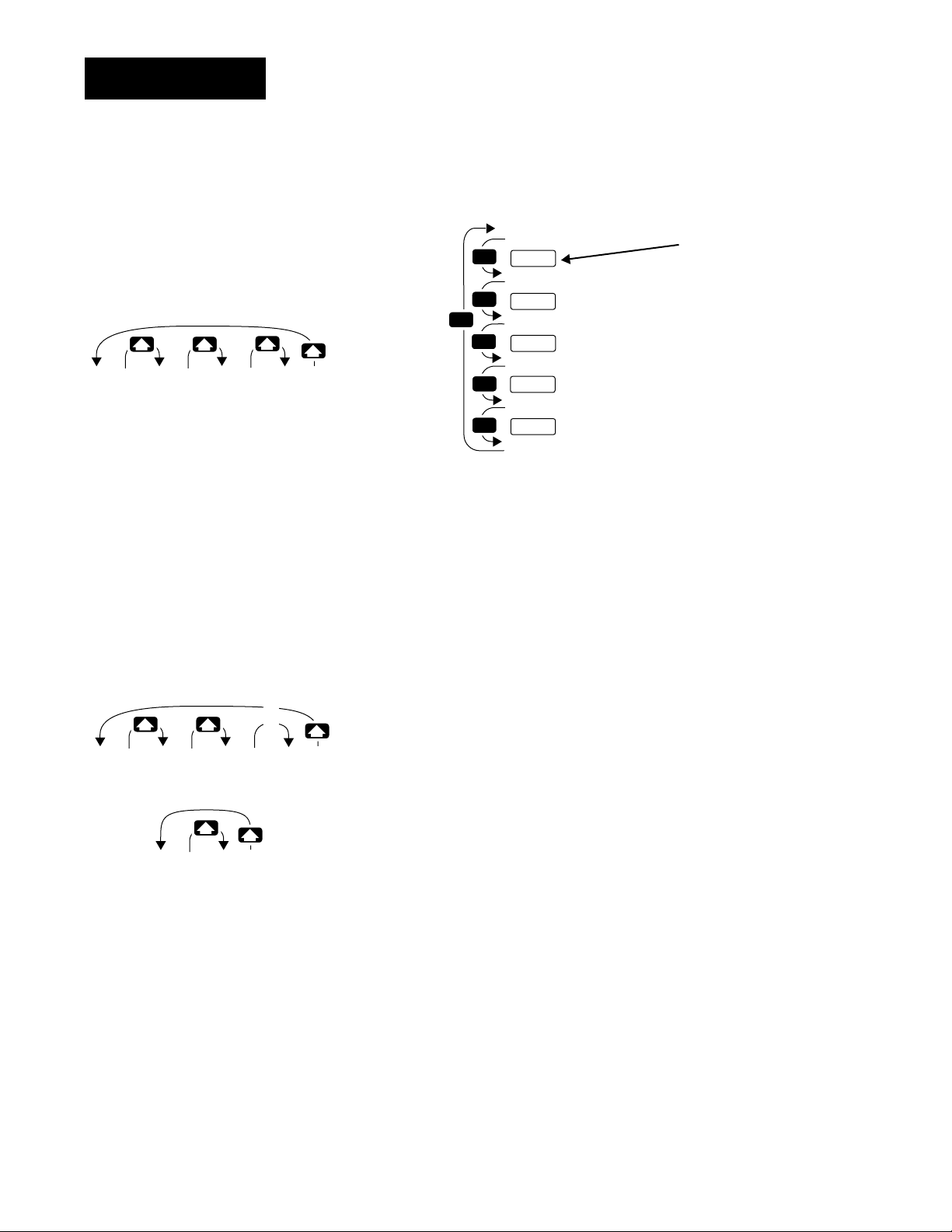
Setup-Comm
Reaching the Communications Menu
❶ Begin in the Display Loop, and
press the Up-arrow > and Downarrow < keys simultaneously for
three seconds to reach the Setup
Menus.
[Inpt]
[`Set]
Input
Menu
p. 4.2
[OtPt] [gLbL] [COm]
[`Set] [`Set]
Output
Menu
p. 4.18
Global
Menu
p. 4.34
[`Set]
Communications
Menu
p. 4.44
❷ Press the Up-arrow key > to select
one of the Setup Menus.
❸ Press the Mode key µ to step
through the prompts.
MODE
MODE
MODE
MODE
MODE
MODE
[COm]
[`Set]
Setup Prompt
[BaUd]
Baud Rate
[Data]
Data Bits and Parity
[Prot]
Protocol Type
[addr]
*Address
[IntF]
*Interface Type
*Prompts may not
appear, depending
on controller configuration.
Enter your settings,
from the controller's
upper display.
…
…
[9600]
[baUD]
[`300]
[baUD] [baUD]
[1200] [4800]
[`485][`422]
[Intf] [Intf]
…
[baUD]
❹ Press the Up-arrow key > or the
Down-arrow key < to select one of
the prompt values.
Figure 4.44 Navigating the
Communications Menu.
˜
NOTE:
The Communications Menu
appears only on controllers
equipped with communications
hardware (98_ _-_ _ _ _-_R_ _,
98 _ _-_ _ _ _-_U_ _ or 98_ _-_ _
_ _-_S_ _).
Data Communications with
See
the Series 988 Family of
Controllers
tion on communications.
for detailed informa-
4.44 WATLOW Series 988 User’s Manual
Setup Menus, Chapter 4
Page 71

Setup-Comm
Communications Prompts
When you are in the Setup menus, the Series 988 displays the menu
selection ( [InPt], [OtPt], [GLbL] or [COM] ) in the upper display, and
[`SEt] in the lower display.
The Up-arrow > or Down-arrow key < selects another menu. Press the
Mode key µ to display the first prompt in the lower display and its value
in the upper display. Use the Up-arrow > and Down-arrow < keys to
change the value in the upper display. The new value will not take effect
until after a five-second delay or until you press the Mode key µ.
[bAUd]
[dAtA]
Baud Rate
Select the communications speed.
[bAUd] This prompt appears only on controllers equipped with communications hardware (98_ _-_ _ _ _-_R_ _, 98_ _-_ _ _ _-_U_ _ or 98_ _-_ _ _ __S_ _).
Default
↓
[9600] [`300] [`600] [1200] [2400] [4800]
[bAUd] [bAUd] [bAUd] [bAUd] [bAUd] [bAUd]
Data Bits and Parity
Select the communications format (start bit = 1, stop bit = 1).
• Setting [Prot] to [Mod] automatically sets [dAtA] to [``8n].
[dAtA] This prompt appears only on controllers equipped with communi-
cations hardware (98_ _-_ _ _ _-_R_ _, 98_ _-_ _ _ _-_U_ _ or 98_ _-_ _ _ __S_ _).
Setup Menus, Chapter 4
Default
↓
[``7o] [``7E] [``8n]
[dAtA] [dAtA] [dAtA]
WATLOW Series 988 User’s Manual 4.45
Page 72

Setup-Comm
[Prot]
[Addr]
Protocol Type
Select the communications protocol.
• [FULL] selects ANSI X3.28 2.2 - A.3.
• [``on] selects Xon/Xoff.
• [Mod] selects Modbus
[Prot] This prompt appears only on controllers equipped with communi-
cations hardware (98_ _-_ _ _ _-_R_ _, 98_ _-_ _ _ _-_U_ _ or 98_ _-_ _ _ __S_ _).
Default
↓
[FULL] [``On] [mod]
[Prot] [Prot] [Prot]
Address
Select an address for the controller. The computer will use this address
when communicating with this controller.
[Addr] This prompt appears only on controllers equipped with communications hardware for EIA/TIA-485 and EIA/TIA-422.
If Default
↓↓
[`485] [```0]…[``31]
[IntF] [Addr] [Addr]
[`422] [```0]…[```9]
[Intf] [Addr] [Addr]
[Mod] [```0] …[```1]… [`247]
[Intf] [Addr] [Addr] [Addr]
4.46 WATLOW Series 988 User’s Manual
Setup Menus, Chapter 4
Page 73

Setup-Comm
[IntF]
[IntF]
Interface Type
Select the interface type for Output 4, Option S.
• [`485] selects EIA/TIA-485.
• [`422] selects EIA/TIA-422.
[IntF] This prompt appears only on controllers equipped with communications
hardware for EIA/TIA-485 and EIA/TIA-422 (98_ _-_ _ _ _-_S_ _).
Default
↓
[`485] [`422]
[IntF] [IntF]
Interface Type
Select the interface type for Output 4, Option U.
• [`485] selects EIA/TIA-485.
• [`232] selects EIA/TIA-232.
[IntF] This prompt appears only on controllers equipped with communications
hardware for EIA/TIA-485 and EIA/TIA-232 (98_ _-_ _ _ _-_U_ _).
Default
↓
[`232] [`485]
[IntF] [IntF]
Setup Menus, Chapter 4
WATLOW Series 988 User’s Manual 4.47
Page 74
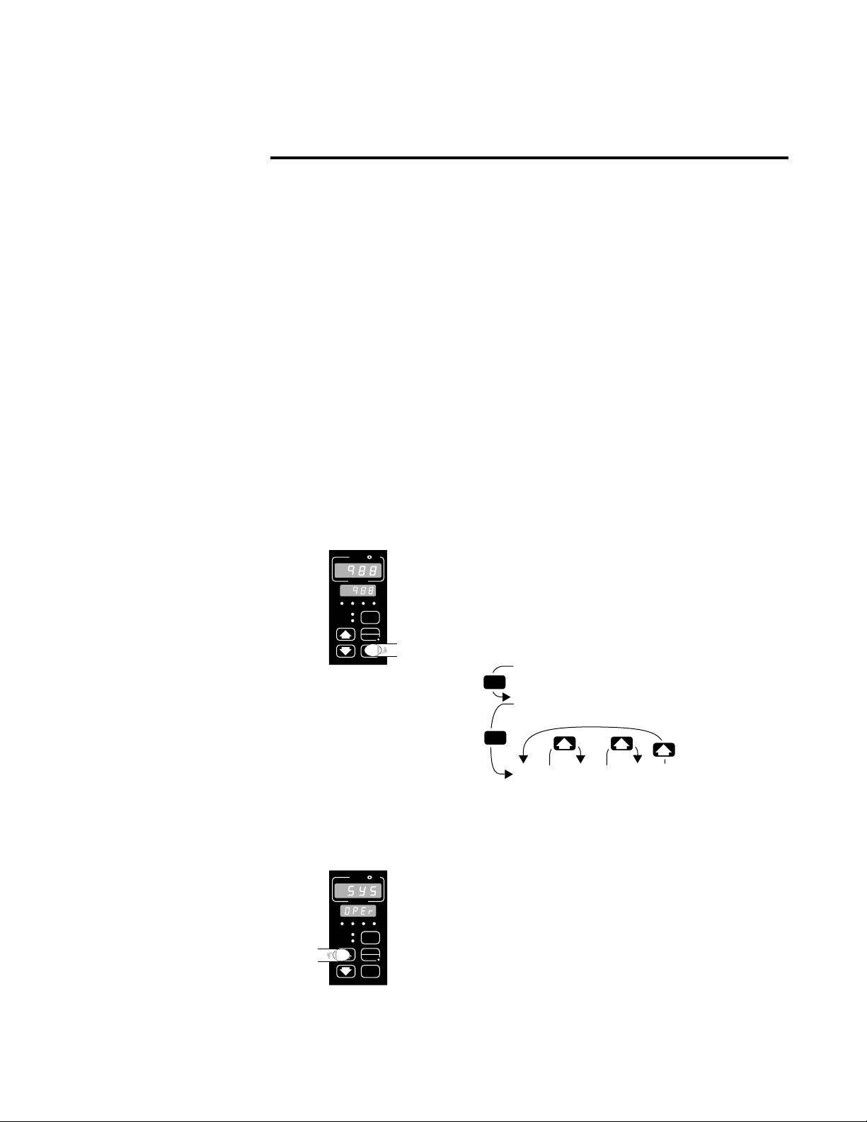
Chapter 5 The Operation Menus
Navigating the Operation Menus
To reach the Operation Menus, begin in the Display Loop and press the
Mode key µ. Depending on the controller configuration, either the Set
Point 2 prompt [`SP2], the Idle Set Point prompt [IdSP] or the Operation
Menu prompt [OPEr] will appear in the lower display. The three Operation
Menus are: System [`SYS]; PID A [PidA]; and PID B [Pidb]. Use the
Mode key µ to step past the Set Point 2 prompt [`SP2] or the Idle Set
Point prompt [IdSP], if they appear (see prompt information). Upon reach-
˜
NOTE:
Press the Display
key ∂ to return to
the Display Loop
from any point in
any menu.
ing the Operation Menu prompt [OPEr] use the Up-arrow > or Down-
arrow < key to select a menu and the Mode key µ to step through a
menu.
You will not see every prompt in any of these menus. The unit’s configuration and model number determine which prompts appear. After stepping
through each menu, the Series 988 returns to the Operation Menu prompt
[OPEr]. Use the Up-arrow > and Down-arrow < keys to select the next
menu, or use the Mode key µ to advance through the same menu again.
To move backwards through the menu hold the Mode key µ down and
press the Up-arrow key >. Use the Up-arrow > or Down-arrow <
key to change the prompt setting.
Figure 5.1 Navigating the
Operation Menus.
W
PROCESS
L1 L2 L3 L4
DEV
% OUT
SERIES 988
W
PROCESS
L1 L2 L3 L4
DEV
% OUT
SERIES 988
A
A
TL
DISPLAY
AUTO
MAN
MODE
TL
DISPLAY
AUTO
MAN
MODE
W
❶ Begin in the Display Loop, and press the Mode key
µ to reach the Set Point 2 prompt [`SP2], the Idle
Set Point prompt [IdSP] or the Operation Menu
[OPEr].
[`988]
[`SP2]
MODE
Set Point 2
[`988]
Menu
p. 5.2
Idle Set Point
[PIDA]
[OPEr]
PID A
Menu
p. 5.9
[PIdb]
[OPEr]
PID B
Menu
p. 5.9
[IdSP]
MODE
[`SyS]
[OPEr]
System
W
❷ Use the Mode key µ to step past the Set Point 2
prompt [`SP2] or the Idle Set Point prompt [IdSP], if
they appear (see prompt information). Upon reaching
the Operation Menu prompt [OPEr] use the Up-arrow
> key to select a menu.
Operation Menus, Chapter 5
WATLOW Series 988 User’s Manual 5.1
Page 75
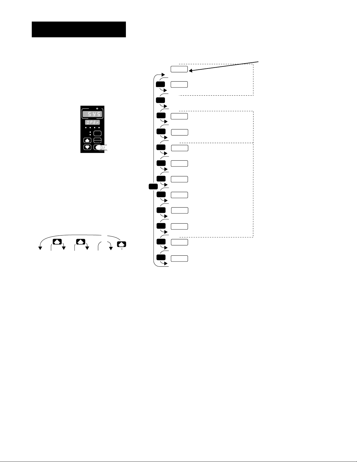
Operation-System
Reaching the System Menu
W
TL
W
A
PROCESS
L1 L2 L3 L4
DEV
DISPLAY
% OUT
AUTO
MAN
MODE
SERIES 988
❸ Select the System Menu, then
press the Mode key µ to step
through the prompts.
…
…
[-999]
[A2LO]
[-998]
[A2LO]
[-997]
[A2LO]
…
[```0]
[A2LO]
MODE
MODE
MODE
MODE
MODE
MODE
MODE
MODE
MODE
MODE
MODE
MODE
MODE
[`SP2]
[IdSP]
[`SyS]
[`SP2]
[Ei1S]
[Ei2S]
[A2LO]
[A2HI]
[A3LO]
[A3HI]
[A4LO]
[A4HI]
[`AUT]
[`L-r]
*Set Point 2
*Idle Set Point
Operation Prompt
*Event Input 1 Status
*Event Input 2 Status
*Alarm 2 Low
*Alarm 2 High
*Alarm 3 Low
*Alarm 3 High
*Alarm 4 Low
*Alarm 4 High
*Auto-tune
*Local-remote
Enter your settings,
from the controller's
upper display.
Set Points (p. 5.3)
Event Input (p. 5.4)
Alarms (p. 5.4)
❹ Press the Up-arrow key > to step
through the prompt values. The
Down-arrow key < backs through
the values.
Figure 5.2 The System Menu.
5.2 WATLOW Series 988 User’s Manual
*Prompts may not appear, depending
on controller configuration.
Operation Menus, Chapter 5
Page 76

Operation-System
˜
NOTE:
Decimal points may
not always be in the
position specified
below depending
on the the settings
in the Decimal 1
[dEC1] and Decimal
2 [dEC2] parame-
ters in the Input
Menu.
[`SP2]
System Prompts
After you step past the Set Point 2 prompt [`SP2] and the Idle Set Point
prompt [IdSP] to the Operation menus, the Series 988 displays the menu
selection ( [`SYS], [PidA] or [PidB] ) in the upper display and [OPEr] in
the lower display.
The Up-arrow > or Down-arrow key < selects another menu. Press the
Mode key µ to display the first prompt in the lower display and its value
in the upper display. Use the Up-arrow > and Down-arrow < keys to
change the value in the upper display. The new value will not take effect
until after a five-second delay or until you press the Mode key µ.
Set Point 2
Select a second set point that will activate output 2. This allows you to
boost the heating or cooling action of the output 1 device.
• The range and default settings depend on the [`In1], [`rL1] and
[`rH1] settings (Input Menu).
[IdSP]
[`SP2] This prompt appears only if [`Ot1] and [`Ot2] (Output Menu) are
both set to [``Ht] or [``CL].
[`rL1] … [`rH1]
[`SP2] [`SP2]
Idle Set Point
Select the set point to be activated by an event input. This allows you
to select a temperature that will be maintained when the application is
idle.
• The range and default settings depend on the [`In1], [`rL1] and
[`rHI] settings (Input Menu).
[IdSP] This prompt appears only if [`Ei1] or [`Ei2] (Global Menu) is set
to [IdSP].
[`rL1] … [`rH1]
[IdSP] [IdSP]
Operation Menus, Chapter 5
WATLOW Series 988 User’s Manual 5.3
Page 77

Operation-System
[Ei1S]
[Ei2S]
Event Input 1 Status
Indicates whether the event input 1 circuit is open or closed (read
only).
[Ei1S] This prompt appears only if [`Ei1] (Global Menu) is set to something other than [``no].
Default
↓
[OpEn] [CLOS]
[Ei1S] [Ei1S]
Event Input 2 Status
Indicates whether the event input 2 circuit is open or closed (read
only).
[Ei2S] This prompt appears only on controllers equipped with a second
digital event input (98_ _-_5_ _-_ _ _ _) and with [`Ei2] (Global Menu) set
to something other than [``no].
[A2LO]
Default
↓
[OpEn] [CLOS]
[Ei2S] [Ei2S]
Alarm 2 Low
Select the low trigger value for the output 2 alarm.
[A2LO] This prompt appears only if [`AL2] (Output Menu) is set to something other than [``no].
If Default
↓↓
lowest
[`Pr1] or [`pr2] value of … value of … [A2HI]
[`AL2] [`AL2] sensor [`rL1] (or [`rL2] ) [A2LO]
(Output Menu) range (Input Menu)
[`dE1] or [`dE2] or [rAtE] [-999] … [```0]
[`AL2] [`AL2] [`AL2] [A2LO] [A2LO]
(Output Menu)
5.4 WATLOW Series 988 User’s Manual
Operation Menus, Chapter 5
Page 78

Operation-System
[A2HI]
[A3LO]
Alarm 2 High
Select the high trigger value for the output 2 alarm.
[A2HI] This prompt appears only if [`AL2] (Output Menu) is set to something other than [``no].
If Default
↓↓
highest
[`Pr1] or [`pr2] [A2LO] … value of … value of
[`AL2] [`AL2] [A2HI] [`rH1] (or [`rH2] ) sensor
(Output Menu) (Input Menu) range
[`dE1] or [`dE2] or [rAtE] [```0] … [`999] … [9999]
[`AL2] [`AL2] [`AL2] [A2HI] [A2HI] [A2HI]
(Output Menu)
Alarm 3 Low
Select the low trigger value for the output 3 alarm.
[A3LO] This prompt appears only if [`AL3] (Output Menu) is set to something other than [``no].
If Default
↓↓
lowest
[`Pr1] or [`pr2] value of … value of … [A3HI]
[`AL3] [`AL3] sensor [`rL1] (or [`rL2] ) [A3LO]
(Output Menu) range (Input Menu)
[`dE1] or [`dE2] or [rAtE] [-999] … [```0]
[`AL3] [`AL3] [`AL3] [A3LO] [A3LO]
(Output Menu)
Operation Menus, Chapter 5
WATLOW Series 988 User’s Manual 5.5
Page 79

Operation-System
[A3HI]
[A4LO]
Alarm 3 High
Select the high trigger value for the output 3 alarm.
[A3HI] This prompt appears only if [`AL3] (Output Menu) is set to something other than [``no].
If Default
↓↓
highest
[`Pr1] or [`pr2] [A3LO] … value of … value of
[`AL3] [`AL3] [A3HI] [`rH1] (or [`rH2] ) sensor
(Output Menu) (Input Menu) range
[`dE1] or [`dE2] or [rAtE] [```0] … [`999] … [9999]
[`AL3] [`AL3] [`AL3] [A3HI] [A3HI] [A3HI]
(Output Menu)
Alarm 4 Low
Select the low trigger value for the output 4 alarm.
[A4LO] This prompt appears only if [`AL4] (Output Menu) is set to some-
thing other than [``no].
If Default
↓↓
lowest
[`Pr1] or [`pr2] value of … value of …[A4HI]
[`AL4 [`AL4] sensor [`rL1] (or [`rL2] ) [A4LO]
(Output Menu) range (Input Menu)
[`dE1] or [`dE2] or [rAtE] [-999] … [```0]
[`AL4] [`AL4] [`AL4] [A4LO] [A4LO]
(Output Menu)
5.6 WATLOW Series 988 User’s Manual
Operation Menus, Chapter 5
Page 80

Operation-System
[A4HI]
[`AUt]
Alarm 4 High
Select the high trigger value for the output 4 alarm.
[A4HI] This prompt appears only if [`AL4] (Output Menu) is set to some-
thing other than [``no].
If Default
↓↓
highest
[`Pr1] or [`pr2] [A4LO] … value of … value of
[`AL4] [`AL4] [A4HI] [`rH1] (or [`rH2]) sensor
(Output Menu) (Input Menu) range
[`dE1] or [`dE2] or [rAtE] [```0] … [`999] … [9999]
[`AL4] [`AL4] [`AL4] [A4HI] [A4HI] [A4HI]
(Output Menu)
Auto-tune
Initiate an auto-tune.
[Pidb] appears only on controllers with enhanced software (98_B-_ _ _ _-_
_ _) and with [ALgO] (Global Menu) set to [Pid2] or [cscd].
NOTE:
For more information on auto-tune
see Chapter 7.
[`AUt] This prompt always appears.
Default
↓
[`OFF] [PidA] [Pidb]
[`AUt] [`AUt] [`AUt]
Operation Menus, Chapter 5
WATLOW Series 988 User’s Manual 5.7
Page 81

Operation-System
[`L-r]
Local-remote
Select a local or remote set point. With [```r] selected the controller
displays the remote set point rather than the internal (local) set point, and
the set point cannot be changed with the Up-arrow or Down-arrow key.
[`L-r] This prompt appears only if [`rSP] (Input Menu) is set to [``On].
Default
↓
[```L] [```r]
[`L-r] [`L-r]
5.8 WATLOW Series 988 User’s Manual
Operation Menus, Chapter 5
Page 82
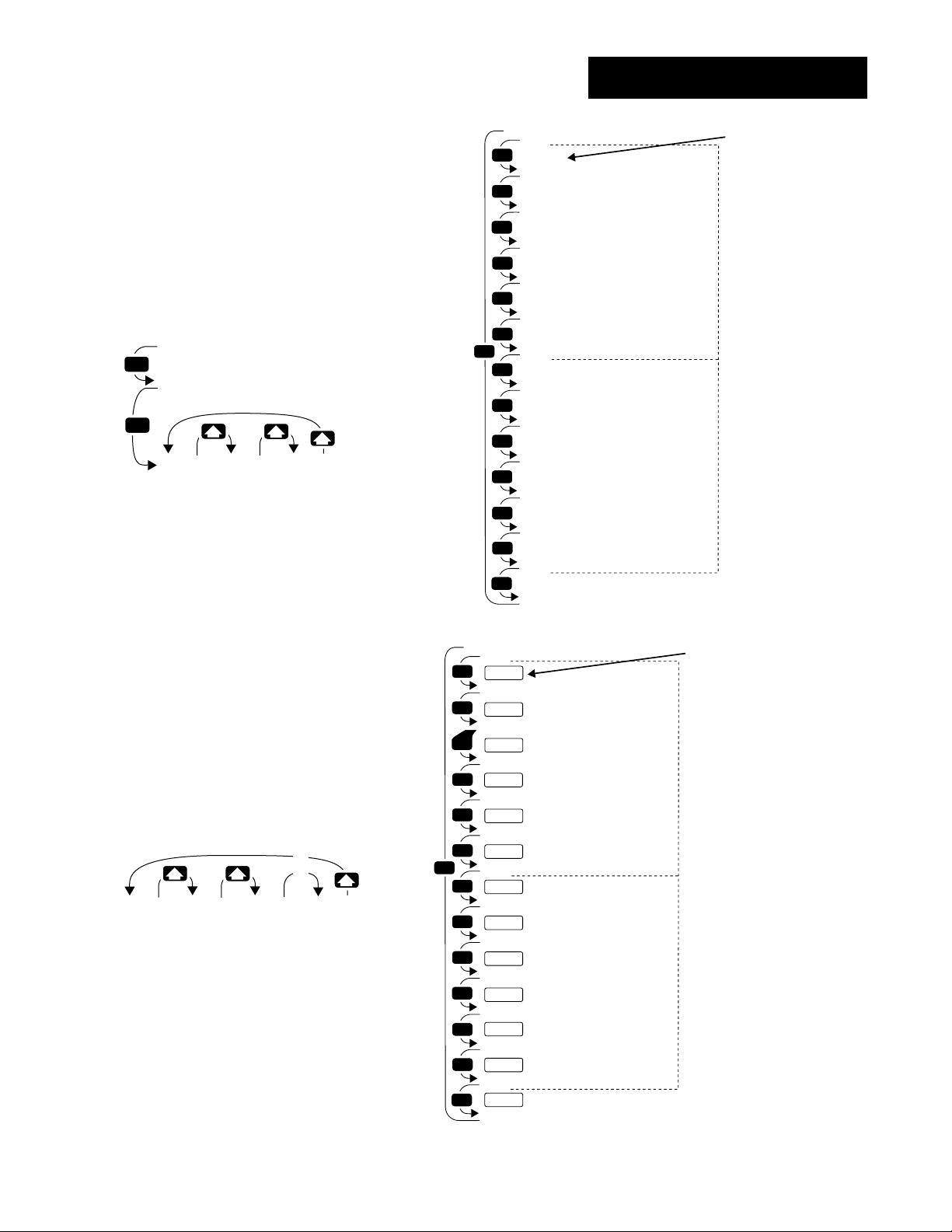
MODE
*Cycle Time,
Output 1B
*Rate,
Output 1B
*Derivative,
Output 1B
*Operation Prompt
*Proportional Band, Output 1B
*Reset,
Output 1B
*Integral,
Output 1B
Enter your settings,
from the controller's
upper display.
MODE
MODE
MODE
MODE
MODE
MODE
MODE
MODE
MODE
MODE
MODE
MODE
Output 2 (p. 5.13)
Output 1 (p. 5.10)
*Cycle Time,
Output 2B
*Rate,
Output 2B
*Derivative,
Output 2B
*Proportional Band, Output 2B
*Reset,
Output 2B
*Integral,
Output 2B
*Dead Band B
MODE
[PIdb]
[OPer]
{Pb1b]
[RE1b]
[It1b]
[rA1b]
[de1b]
{CT1b}
[Pb2b]
[re2b]
[It2b}
[rA2b]
[dE2b]
[Ct2b]
[db`b]
Operation-PID A or B
Reaching the PID Menus
❶ Begin in the Display Loop, and
press the Mode key µ to reach the
Set Point 2 prompt [`SP2], the Idle
Set Point prompt [IdSP] or the
System Menu [`SYS].
[`988]
[`SP2]
MODE
[`988]
[IdSP]
MODE
[`SyS]
[OPEr]
System
❷ Use Mode key µ to step past
the Set Point 2 prompt [`SP2] and
the Idle Set Point prompt [IdSP], if
they appear (see prompt information). Upon reaching the Operation
Menu prompt [OPEr] use the Up-
arrow > key to select a menu.
❸ Press the Mode key µ to step
through the prompts.
[`)00]
[dE1A]
❹ Press the Up-arrow key > to
step through the prompt values.
The Down-arrow key < backs
through the values.
Figure 5.9 The PID Menus.
Operation Menus, Chapter 5
Menu
p. 5.2
[`)01]
[dE1A]
Set Point 2
Idle Set Point
[PIDA]
[OPEr]
PID A
Menu
p. 5.9
[`)02]
[dE1A]
[PIdb]
[OPEr]
PID B
Menu
p. 5.9
…
…
…
[`(99]
[dE1A]
MODE
MODE
MODE
MODE
MODE
MODE
MODE
MODE
MODE
MODE
MODE
MODE
MODE
MODE
[PIDA]
Operation Prompt
[Oper]
[````]
[Pb1A]
Proportional Band, Output 1A
[````]
[RE1A]
*Reset,
Output 1A
[````]
[It1A]
*Integral,
[````]
[rA1A]
*Rate,
[````]
[dE1A]
*Derivative,
[````]
*Cycle Time,
[Ct1A]
[````]
[Pb2A]
*Proportional Band, Output 2A
[````]
[Re2A]
*Reset,
[````]
[It2A]
*Integral,
[````]
[rA2A]
*Rate,
[````]
[dE2A]
*Derivative,
[````]
[Ct2A]
*Cycle Time,
[````]
[db`A]
*Dead Band A
Output 1
Output 1
Output 2
Output 2
Output 2
WATLOW Series 988 User’s Manual 5.9
A
A
Output 1
Output 1
A
A
A
Output 2
Output 2
Enter your settings,
from the controller's
upper display.
Output 1 (p. 5.10)
A
A
Output 2 (p. 5.13)
A
A
*Prompts may not
appear, depending on
controller configuration.
Page 83

Operation-PID A or B
˜
NOTE:
Decimal points may
not always be in the
position specified
below depending
on the the settings
in the Decimal 1
[dEC1] and Decimal
2 [dEC2] parame-
ters in the Input
Menu.
[Pb1A]
[Pb1b]
PID A or PID B Prompts
After you step past the Set Point 2 prompt [`SP2] and the Idle Set Point
prompt [IdSP] to the Operation menus, the Series 988 displays the menu
selection ( [`SYS], [PidA] or [Pidb] ) in the upper display and [OPEr] in
the lower display.
The Up-arrow > or Down-arrow key < selects another menu. Press the
Mode key µ to display the first prompt in the lower display and its value
in the upper display. Use the Up-arrow > and Down-arrow < keys to
change the value in the upper display. The new value will not take effect
until after a five-second delay or until you press the Mode key µ.
Proportional Band, Output 1A or 1B
Select the proportional band for PID output 1. If set to [```0] it func-
tions as an on/off control, and the switching differential is determined by
the [HYS1] value (Output Menu). The decimal precision is determined by
[dEC1] (Input Menu).
[Pb1A] This prompt always appears.
˜
NOTE:
The PID B Menu
appears only on
controllers with
enhanced software
(98_B-_ _ _ _-_ _ _ _)
and with [AhgO] set
to [Pid2].
If Default
↓↓
[``US]
[`dFL] [`C_F] [Pb1A] [Pb1A] [Pb1A]
(Calibration Menu)(Global Menu)
[``US]
[`dFL] [`C_F] [Pb1A] [Pb1A] [Pb1A]
(Calibration Menu)(Global Menu)
[``SI]
[`dFL] [ALgO] [Pb1A] [Pb1A] [Pb1A]
(Calibration Menu) (Global Menu)
&
[``°F] [```0]…[``25]…[9999]
&
[`r†d] [``)0]…[``25]…[99(9]
Input 1 or 2
(Input Menu)
&
[``°C] [```0]…[``14]…[9999]
&
[`r†d] [``)0]…[``14]…[99(9]
Input 1 or 2
(Input Menu)
&
[Pid2] [``)0]…[``#0]…[99(9]
[Pb1A] [Pb1A] [Pb1A]
[Pb1A] [Pb1A] [Pb1A]
% of span
5.10 WATLOW Series 988 User’s Manual
Operation Menus, Chapter 5
Page 84

Operation-PID A or B
[rE1A]
[rE1b]
[It1A]
[It1b]
Reset, Output 1A or 1B
Tune reset to eliminate the offset or droop between the set point and
the actual process temperature for PID output 1. When set to [```0]
reset is disabled.
[rE1A] This prompt appears only if [`dFL] (Calibration Menu) is set to
[``US] and [Pb1A] is not set to [```0].
If Default
↓↓
[00)0] … [99(9] repeats/min.
[rE1A] [rE1A]
[`Pdr] [=0)0]% … [``)0] % … [10)0] %
[ALG0] [rE1A] [rE1A] [rE1A]
(Global Menu)
Integral, Output 1A or 1B
Tune integral to eliminate the offset or droop between the set point
and the actual process temperature for PID output 1. When set to
[```0] integral is disabled.
˜
NOTE:
The PID B Menu
appears only on
controllers with
enhanced software
(98_B-_ _ _ _-_ _ _ _).
[It1A] This prompt appears only if [`dFL] (Calibration Menu) is set to
[``S1] and [Pb1A] is not set to [```0].
Default
↓
[`)00] … [9(99] min. / repeat
[It1A] [It1A]
Operation Menus, Chapter 5
WATLOW Series 988 User’s Manual 5.11
Page 85

Operation-PID A or B
[rA1A]
[rA1b]
[dE1A]
[dE1b]
Rate, Output 1A or 1B
Adjust the rate to eliminate overshoot on startup or after the set
point changes. The rate setting will not influence the percent power if the
process temperature is more than twice the proportional band from the set
point. When set to [```0] rate is disabled.
[rA1A] This prompt appears only if [`dfL] (Calibration Menu) is set to
[``US] and [Pb1A] is set higher than [```0].
Default
↓
[`)00] … [`(99] min.
[rA1A] [rA1A]
Derivative, Output 1A or 1B
Adjust the derivative to eliminate overshoot on startup or after the
set point changes. The derivative setting will not influence the percent
power if the process temperature is more than twice the proportional band
from the set point. When set to [```0] derivative is disabled.
˜
NOTE:
The PID B Menu
appears only on
controllers with
enhanced software
(98_B-_ _ _ _-_ _ _ _).
[dE1A] This prompt appears only if [`dFL] (Calibration Menu) is set to
[``SI] and [Pb1A] is set higher than [```0].
Default
↓
[`)00] … [`(99]
[dE1A] [dE1A]
min.
5.12 WATLOW Series 988 User’s Manual
Operation Menus, Chapter 5
Page 86

Operation-PID A or B
[Ct1A]
[Ct1b]
[Pb2A]
[Pb2B]
Cycle Time, Output 1A or 1B
Select the time, in seconds, of a complete on/off cycle.
[Ct1A] This prompt appears only if [`In1] (Input Menu) is not set to a
process, [CntL] (Global Menu) is not set to [CSCd] and [Pb1A] is set higher than [```0].
If Default
↓↓
mechanical [``%0] … [`1)0] … [99(9] sec.
relay [Ct1A] [Ct1A] [Ct1A]
outputs
open collector [brSt] [``)1] … [``!0] … [99(9] sec.
or solid-state [Ct1A] [Ct1A] [Ct1A] [Ct1A]
relay outputs
Proportional Band, Output 2A or 2B
Select the proportional band for PID output 2. If set to [```0] it func-
tions as an on/off control, and the switching differential is determined by
the [HYS2] value (Output Menu). Decimal precision is determined by the
[`dEC1] or [`dEC2] setting (Input Menu).
˜
NOTE:
The PID B Menu
appears only on
controllers with
enhanced software
(98_B-_ _ _ _-_ _ _ _).
[Pb2A] This prompt appears only if [CntL] (Global Menu) is not set to
[CSCd] and if [`Ot2] (Output Menu) is set to [``Ht] or [``CL] or if [ALg0]
(Global Menu) is set to [dUPL].
If Default
↓↓
[``US]
[`dFL] [`C_F] [Pb2A] [Pb2A] [Pb2A]
(Calibration Menu) (Global Menu)
[``US]
[`dFL] [`C_F] [Pb2A] [Pb2A] [Pb2A]
(Calibration Menu) (Global Menu)
[``SI] [``)0]…[``#0]…[99(9]
[`dFL] [Pb2A] [Pb2A] [Pb2A]
(Calibration Menu)
[``°F] [```0]…[``25]…[9999]
&
[`r†d] [``)0]…[``25]…[99(9]
&
Input 1 or 2
(Input Menu)
[``°C] [```0] [``14]…[9999]
&
[`r†d] [``)0]…[``14]…[99(9]
&
Input 1 or 2
(Input Menu)
[Pb2A] [Pb2A] [Pb2A]
[Pb2A] [Pb2A] [Pb2A]
% of span
Operation Menus, Chapter 5
WATLOW Series 988 User’s Manual 5.13
Page 87

Operation-PID A or B
[rE2A]
[rE2b]
[It2A]
[It2b]
Reset, Output 2A or 2B
Tune reset to eliminate the offset or droop between the set point and
the actual process temperature for PID A output 2. When set to [```0]
reset is disabled.
[rE2A] This prompt appears only if [`dFL] (Calibration Menu) is set to
[``US] and [Pb2A] is set higher than [```0].
If Default
↓↓
[00)0] … [99(9] repeats/min.
[rE2A] [rE2A]
[`Pdr] [=0)0] %… [``)0] %… [10)0] %
[ALG0] [rE2A] [rE2A] [rE2A]
(Global Menu)
Integral, Output 2A or 2B
Tune integral to eliminate the offset or droop between the set point
and the actual process temperature for PID output 2. When set to
[```0] integral is disabled.
˜
NOTE:
The PID B Menu
appears only on
controllers with
enhanced software
(98_B-_ _ _ _-_ _ _ _).
[It2A] This prompt appears only if [`dFL] (Calibration Menu) is set to
[``SI] and [Pb2A] is set higher than [```0].
Default
↓
[`)00] … [9(99] repeats / min.
[It2A] [It2A]
5.14 WATLOW Series 988 User’s Manual
Operation Menus, Chapter 5
Page 88

Operation-PID A or B
[rA2A]
[rA2b]
[dE2A]
[dE2b]
Rate, Output 2
Adjust the rate to eliminate overshoot on startup or after the set
point changes. The rate setting will not influence the percent power if the
process temperature is more than twice the proportional band from the
set point. When set to [```0] rate is disabled.
[rA2A] This prompt appears only if [`dFL] (Calibration Menu) is set to
[``US] and [Pb2A] is set higher than [```0].
Default
↓
[`)00] … [`(99] min.
[rA2A] [rA2A]
Derivative, Output 2A or 2B
Adjust the derivative to eliminate overshoot on startup or after the
set point changes. The derivative setting will not influence the percent
power if the process temperature is more than twice the proportional band
from the set point. When set to [```0] derivative is disabled.
˜
NOTE:
The PID B Menu
appears only on
controllers with
enhanced software
(98_B-_ _ _ _-_ _ _ _).
[dE2A] This prompt appears only if [`dFL] (Calibration Menu) is set to
[``SI] and [Pb2A] is set higher than [```0].
Default
↓
[`)00] … [`(99] min.
[dE2A] [dE2A]
Operation Menus, Chapter 5
WATLOW Series 988 User’s Manual 5.15
Page 89

Operation-PID A or B
[Ct2A]
[Ct2b]
[db`A]
[db`b]
Cycle Time, Output 2A or 2B
Select the time, in seconds, of a complete on/off cycle.
[Ct2A] This prompt appears only if [CntL] (Global Menu) is not set to
[CSCd] and [Pb2A] is set higher than [```0].
If Default
↓↓
mechanical [``%0] … [`1)0] … [99(9]
relay [Ct2A] [Ct2A] [Ct2A]
outputs
open collector [brSt] [``)1] … [``!0] … [99(9]
or solid-state [Ct2A] [Ct2A] [Ct2A] [Ct2A]
relay outputs
Dead Band A or B
Select the width of the zone between the action of the heating output
and the cooling output. If you select a positive value the heat and cool
outputs cannot be energized at the same time. If you select a negative
value, both outputs can be energized at the same time.
˜
NOTE:
The PID B Menu
appears only on
controllers with
enhanced software
(98_B-_ _ _ _-_ _ _ _).
• If a process input is selected the decimal precision will be determined by
the [`dEC1] setting (Input Menu).
[db`A] This prompt appears only if [Pb2A] is set higher than [```0] and
one output performs heating action and the other performs cooling action.
If Default
↓↓
[``°F] [-999] … [```0] … [`999]
[`C_F] [db`A] [db`A] [db`A]
(Global Menu)
[``°C] [-555] … [```0] … [`555]
[`C_F] [db`A] [db`A] [db`A]
(Global Menu)
a process [-999] … [```0] … [`999] units
input is selected [db`A] [db`A] [db`A]
5.16 WATLOW Series 988 User’s Manual
Operation Menus, Chapter 5
Page 90
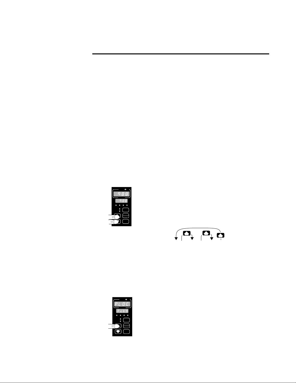
Chapter 6 The Factory Menus
Navigating the Factory Menus
˜
NOTE:
The Factory Menus
will not appear if the
hardware lockout
DIP is set to on.
See Chapter 1 for
more information.
˜
NOTE:
The Factory Menus
can only be entered
when the setup
prompt [`SEt] is
displayed.
˜
NOTE:
Press the Display
key ∂ to return to
the Display Loop
from any point in
any menu.
To reach the Factory Menus, begin in the Display Loop and press the Uparrow > and Down-arrow < keys together and hold for three seconds.
The [`SEt] prompt will appear in the lower display. Press and hold the
Up-arrow > and Down-arrow < keys together again for three seconds
until the [Fcty] prompt appears in the lower display. The Factory Menus
will not appear if the hardware lockout DIP is set to on. (See Chapter 1 for
more information on DIP switch settings.) The three Factory Menus are:
Panel Lockout [PLOC]; Diagnostics [diAg]; and Calibration [`CAL]. Upon
reaching the Factory Menu prompt [Fcty] use the Up-arrow > or Down-
arrow < key to select a menu and the Mode key µ to step through a
menu.
You will not see every prompt in any of these menus. The unit’s configuration and model number determine which prompts appear. After stepping
through each menu, the Series 988 returns to the Factory Menu prompt
[Fcty]. Use the Up-arrow > and Down-arrow < keys to select the next
menu, or use the Mode key µ to advance through the same menu again.
To move backwards through the menu hold down the Mode key µ and
press the Up-arrow key >. Use the Up-arrow > or Down-arrow <
key to change the prompt setting.
W
TL
W
PROCESS
L1 L2 L3 L4
DEV
% OUT
SERIES 988
A
DISPLAY
AUTO
MAN
MODE
❶ Press the Up-arrow > and Down-arrow < keys
together and hold until the [`SEt] prompt appears in
the lower display. Press and hold again until the
[Fcty] prompt appears in the lower display.
Figure 6.1 Navigating the
Factory Menus.
Factory Menus, Chapter 6
W
PROCESS
L1 L2 L3 L4
DEV
% OUT
SERIES 988
A
TL
DISPLAY
AUTO
MAN
MODE
[PLOC] [diAg] [`CAL]
[Fcty] [Fcty] [Fcty]
Panel Diagnostics Calibration
Lockout Menu Menu
Menu p 6.7 p 6.13
p 6.2
W
❷ Use the Up-arrow key > to select one of the
Factory Menus.
WATLOW Series 988 User’s Manual 6.1
Page 91
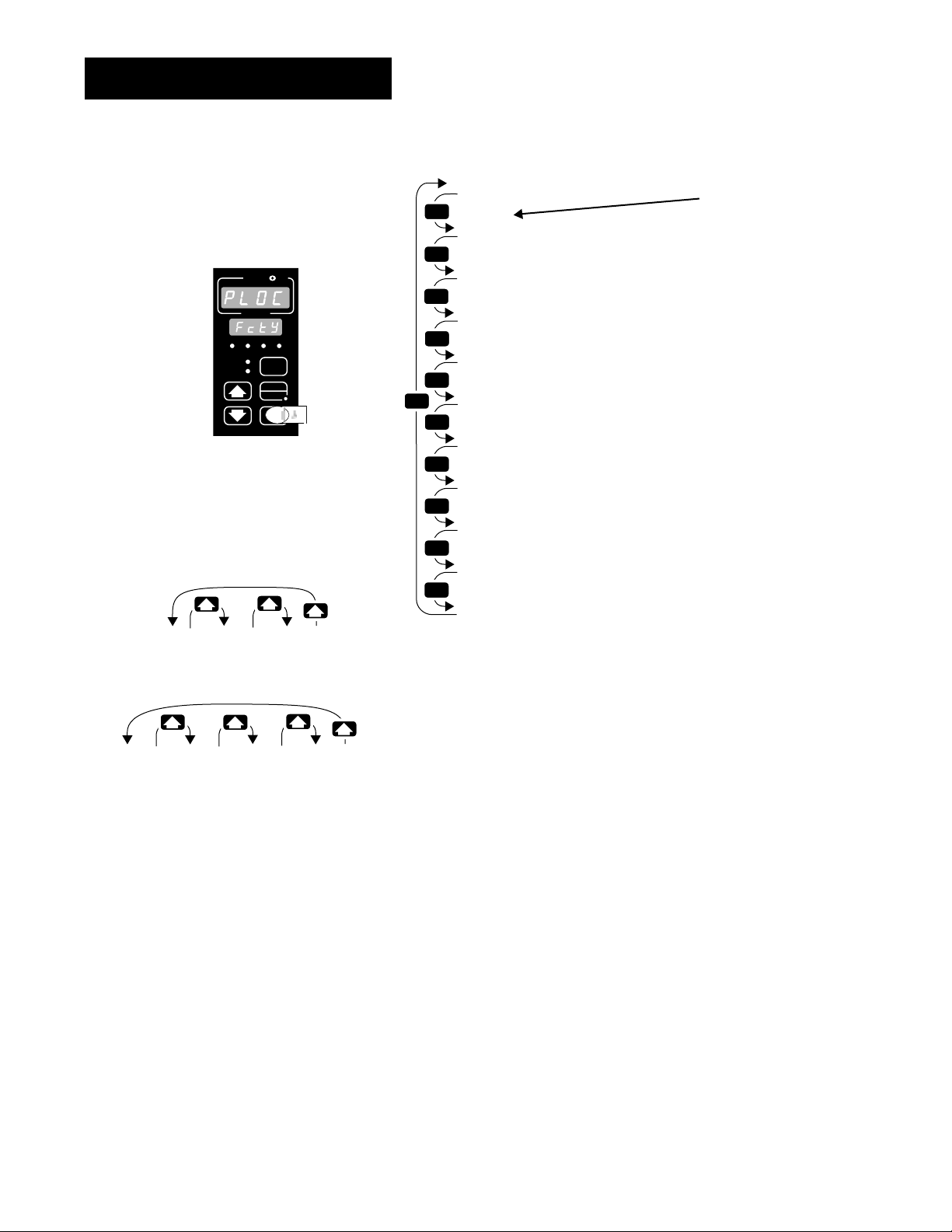
Factory-Panel Lockout
Reaching the Panel Lockout Menu
W
TL
W
A
PROCESS
L1 L2 L3 L4
DEV
DISPLAY
% OUT
AUTO
MAN
MODE
SERIES 988
❸ Select the Panel Lockout Menu,
then press the Mode key µ to step
through the prompts.
[FULL] [rEAd] [nonE]
[InPt] [Inpt] [Inpt]
[PLOC]
Factory Prompt
?
Front Panel Lockout
?
System Menu
?
PID A Menu
?
*PID B Menu
?
Input Menu
?
Output Menu
?
Global Menu
?
*Communications Menu
?
Diagnostics Menu
?
Calibration Menu
MODE
MODE
MODE
MODE
MODE
MODE
MODE
MODE
MODE
MODE
MODE
[Fcty]
[````]
[`LOC]
[````]
[`SYS]
[````]
[PidA]
[````]
[PidB]
[````]
[Inpt]
[````]
[Otpt]
[````]
[GlbL]
[````]
[COM]
[````]
[Diag]
[````]
[`CAL]
*Prompts may not appear, depending
on controller configuration.
Enter your settings,
from the controller’s
upper display.
[```0]
[`LOC]
[```1]
[`LOC]
[```2]
[`LOC]
[```3]
[`LOC]
❹ Press the Up-arrow key > or the
Down-arrow key < to select one of
the prompt values.
Figure 6.2 The Panel Lockout
Menu.
6.2 WATLOW Series 988 User’s Manual
Factory Menus, Chapter 6
Page 92

[`LOC]
Factory-Panel Lockout
Panel Lockout Prompts
When you are in the Factory menus, the Series 988 displays the menu
selection ( [PLOC], [diAg] or [`CAL] ) in the upper display and [FctY] in
the lower display.
The Up-arrow > or Down-arrow key < selects another menu. Press the
Mode key µ to display the first prompt in the lower display and its value
in the upper display. Use the Up-arrow > and Down-arrow < keys to
change the value in the upper display. The new value will not take effect
until after a five-second delay or until you press the Mode key µ.
Front Panel Lockout
Sets the Lockout level for the Front Panel. This allows you to disable
keys on the front of the controller.
ç
CAUTION:
Setting [`LOC] to
[```2] or [```3]
disables the
Auto/Man key å
and will force the
controller into manual mode if an open
sensor occurs.
Verify that the controller is operating
in the desired mode
(auto or manual)
before setting the
lockout level.
Failure to do so
could result in damage to equipment
and or property.
• [```0] enables all keys.
• [```1] disables the Mode key µ.
• [```2] disables the Mode key µ and the Auto/Man key å.
• [```3] disables the Mode key µ and the Auto/Man key å and locks
the set point value.
[`LOC] This prompt always appears.
Default
↓
[```0] [```1] [```2] [```3]
[`LOC] [`LOC] [`LOC] [`LOC]
Factory Menus, Chapter 6
WATLOW Series 988 User’s Manual 6.3
Page 93

Factory-Panel Lockout
The prompts within the Panel Lockout Menu allow you to lockout an
entire menu. You can set the level of lockout to none [nonE], read only
[rEAd], or lockout read and write [FULL].
[`SYS]
[PidA]
System Menu
Select the lockout level for the System Menu. Set the System Menu
lockout to no lockout [none], read only [read] or full lockout [FULL].
[`LOC] This prompt always appears.
Default
↓
[none] [read] [FULL]
[`SYS] [`SYS] [`SYS]
PID A Menu
Select the lockout level for the PID A Menu. Set the PID A Menu lockout to no lockout [none], read only [read] or full lockout [FULL].
[PidA] This prompt always appears.
Default
↓
[none] [read] [FULL]
[PiDA] [pida] [pida]
PID B Menu
[PidB]
Select the lockout level for the PID B Menu. Set the PID B Menu lockout to no lockout [none], read only [read] or full lockout [FULL].
[PidB] This prompt appears only on controllers with enhanced software
(98_B-_ _ _ _-_ _ _ _) and with [ALgO] (Global Menu) set to [Pid2] or
[CntL] (Global Menu) set to [CSCd].
Default
↓
[none] [read] [FULL]
[PiDb] [pidb] [pidb]
6.4 WATLOW Series 988 User’s Manual
Factory Menus, Chapter 6
Page 94

Factory-Panel Lockout
[Inpt]
[Otpt]
Input Menu
Select the lockout level for the Input Menu. Set the Input Menu lockout to no lockout [none], read only [read] or full lockout [FULL].
[InPt] This prompt always appears.
Default
↓
[none] [read] [FULL]
[Inpt] [InPt] [Inpt]
Output Menu
Select the lockout level for the Output Menu. Set the Output Menu
lockout to no lockout [none], read only [read] or full lockout [FULL].
[OtPt] This prompt always appears.
Default
↓
[none] [read] [FULL]
[Otpt] [Otpt] [Otpt]
[GLBL]
Factory Menus, Chapter 6
Global Menu
Select the lockout level for the Global Menu. Set the Global Menu lockout to no lockout [none], read only [read] or full lockout [FULL].
[gLbL] This prompt always appears.
Default
↓
[none] [read] [FULL]
[GLBL] [GLBL] [GLBL]
WATLOW Series 988 User’s Manual 6.5
Page 95

Factory-Panel Lockout
[COM]
[diag]
Communications Menu
Select the lockout level for the Communications Menu. Set the
Communications Menu lockout to no lockout [none], read only [read] or
full lockout [FULL].
[COM] This prompt appears only on controllers equipped with
Communications hardware (98_ _ -_ _ _ _-_R_ _ or 98_ _ -_ _ _ _-_S_ _ ).
Default
↓
[none] [read] [FULL]
[COM] [COM] [COM]
Diagnostics Menu
Select the lockout level for the Diagnostics Menu. Set the Diagnostics
Menu lockout to no lockout [none], read only [read] or full lockout
[FULL].
[diAg] This prompt always appears.
[`CAL]
Default
↓
[none] [read] [FULL]
[Diag] [diag] [diag]
Calibration Menu
Select the lockout level for the Calibration Menu. Set the Calibration
Menu lockout to no lockout [none], read only [read] or full lockout
[FULL].
[`CAL] This prompt always appears.
Default
↓
[none] [read] [FULL]
[`CAL] [`CAL] [`CAL]
6.6 WATLOW Series 988 User’s Manual
Factory Menus, Chapter 6
Page 96
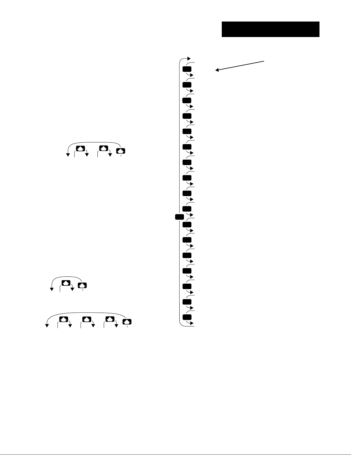
Factory-Diagnostics
Reaching the Diagnostics Menu
❶ Press the Up-arrow > and Down-arrow
< keys together and hold until the
[`SEt] prompt appears in the lower display. Press and hold again until the [Fcty]
prompt appears in the lower display.
[PLOC] [diAg] [`CAL]
[Fcty] [Fcty] [Fcty]
Panel Diagnostics Calibration
Lockout Menu Menu
Menu p 6.7 p 6.13
p 6.2
❷ Use the Up-arrow > key to step from
the Panel Lockout Menu [PLOC] to the
Diagnostics Menu [diag].
❸ Press the Mode key µ to step through
the prompts.
[``no][`YES]
[dISP] [dISP]
[`OFF][out1] … [out4]
[tout] [tout] [tout]
MODE
MODE
MODE
MODE
MODE
MODE
MODE
MODE
MODE
MODE
MODE
MODE
MODE
MODE
MODE
MODE
MODE
MODE
[Diag]
[Fcty]
?
[date]
?
[SOft]
?
[Sn--]
?
[AMB]
?
[Acnt]
?
[`gnd]
?
[cnt1]
?
[cnt2]
?
[ity1]
?
[ity2]
?
[Oty1]
?
[Oty2]
?
[Oty3]
?
[Oty4]
?
[dISP]
?
[tout]
?
[OPLP]
Factory Prompt
Factory Ship Date
Software Revision
Serial Number
Ambient Temperature
Ambient A/D count
Ground A/D count
Input 1 A/D count
Input 2 A/D count
Input 1 Module Type
Input 2 Module Type
Output 1 Module Type
Output 2 Module Type
Output 3 Module Type
Output 4 Module Type
Test Display
Test Outputs
Open Loop
Enter your settings,
from the controller's
upper display.
❹ Press the Up-arrow key > or the Down-
arrow key < to select one of the prompt
values.
In the Diagnostics Menu only the values of
[dISP], [tout] and [OPLP] can be
changed.
Factory Menus, Chapter 6
Figure 6.7 The Diagnostics Menu.
WATLOW Series 988 User’s Manual 6.7
Page 97

Factory-Diagnostics
[DAte]
[sOft]
[Sn--]
Factory Ship Date
Shows the date that the final factory control test was performed. The
first two digits represent the week as numbered from [01--] to [52--].
The second two digits represent the year [--94], [--95], etc…
[dAtE] This prompt always appears.
Software Revision
Shows the controller’s software revision code when set to
letter should match the software revision code on the cover of the manual
that came with your controller; [```n] and W988-XUMN Rev N00.
[SOFt] This prompt always appears.
[[``yyeess]]
. This
Serial Number
Shows the controller’s serial number. The first two letters in the upper
display are to indicate that the controller is in serial number mode. The
right half of the upper display shows the first two digits of the serial number. The lower display shows the last four digits of the serial number.
[AMB]
[Sn34]
[5678]
This is what the controller with the serial number 0988345678 would display.
[Sn--] This prompt always appears.
Ambient Temperature
Shows the ambient temperature at the Input 1 terminals. The temperature is shown in °F in the form [00)0] regardless of the settings of
[deC1], [deC2], [`dfL] or [`C_F].
[AMb] This prompt always appears.
6.8 WATLOW Series 988 User’s Manual
Factory Menus, Chapter 6
Page 98

Factory-Diagnostics
[acnt]
[`gnd]
[cnt1]
[cnt2]
[ity1]
[ity2]
Factory Use Only
These prompts are used only at the factory.
[Acnt] [`gnd] [cnt1] [cnt2] These prompts always appear.
Inputs 1 and 2 Module Types
Displays which input module is installed in the controller. Please document this value before contacting the factory for technical assistance.
Input Types
• [none] No input module
• [``tc] Thermocouple only module
• [Curr] Current detect
• [SLid] Slidewire module
• [UOFF] Universal off
• [Urtd] Universal rtd
• [Utch] Universal high-gain thermocouple
• [UtcL] Universal low-gain thermocouple
• [UMu] Universal millivolts
• [UPrc] Universal process
• [`Ei2] Event input 2
[ity1] [ity2] These prompts always appear.
Factory Menus, Chapter 6
WATLOW Series 988 User’s Manual 6.9
Page 99

Factory-Diagnostics
[Oty1]
[Oty2]
[Oty3]
[Oty4]
Outputs 1, 2, 3 and 4 Module Types
Display the controller’s output module. Please document this value
before contacting the factory for technical assistance.
Output Types
• [none] no output module (A)
• [SSr1] 0.5A solid-state relay (K)
• [SS1S] 0.5A solid-state relay with suppression (B)
• [``dc] switched dc open collector (C)
• [rLyc] form C relay (E)
• [rLcS] form C relay with suppression (D)
• [rLAb] relay A/B (J)
• [Proc] process output (F)
• [Uret] voltage/retransmit (N)
• [Iret] current/retransmit (M)
• [SpLy] power supply (T)
• [`232] EIA/TIA-232 communications (R)
• [`485] EIA/TIA-485 or EIA/TIA-422 communications (S)
• [`232] EIA/TIA-232 or EIA/TIA-485 communications (U)
[Oty1] [Oty2] [Oty3] [Oty4] These prompts always appear.
6.10 WATLOW Series 988 User’s Manual
Factory Menus, Chapter 6
Page 100

Factory-Diagnostics
[disp]
[tout]
Test Displays
Runs a brief test of the controller’s displays and LEDs. To run the test,
scroll through the Diagnostics Menu until [disp] is shown in the lower
display. Use the Up-arrow key > or Down-arrow key < to select
[`YES] from the upper display and press the mode key µ.
The controller will run pattern tests, blink all the LEDs on and off, and
end with the model number in both displays.
[diSP] This prompt always appears.
Default
↓
[``no] [`yes]
[disp] [disp]
Test Outputs
This prompt tests each output. To run the test, scroll through the
Diagnostics Menu until [tout] is shown in the lower display. Use the Uparrow key > or Down-arrow key < to select an output [out1], [out2],
[out3], or [out4]. The LED for that output should light after a second or
two indicating that the output has been successfully energized. Do not
press the mode key µ to activate the test; it starts automatically when
anything other than [`OFF] is selected.
Factory Menus, Chapter 6
If any of the LEDs fail to light contact the factory.
[tout] This prompt always appears.
Default
↓
[`OFF] [out1] [out2] [out3] [out4]
[tout] [tout] [tout] [tout] [tout]
WATLOW Series 988 User’s Manual 6.11
 Loading...