

Page 1
Electrically Release Brakes
ERD Size 005 to 035 & ERD Size 060 to 300
Service Manual
P-2060-WE
SM321Agb - rev 11/04
SM321gb - rev 11/04
Page 2

Page 3

P-2060-WE
SM321Agb - rev 11/04
Electrically Release Brakes
ERD Size 005 to 035
Service Manual
Page 4
We, WARNER ELECTRIC EUROPE, 7, rue Champfleur, B.P. 20095, F-49182 St Barthélemy d’Anjou Cedex
declare that the brakes are made in our factory from St Barthélemy d’Anjou,
and hereafter designated : ERD
are exclusively designed for incorporation into a machine and to be assembled with other equipment with a view to constituting a machine to
which direction 98/37/EC and Electromagnetic Compatibility directive 89/336 as amended apply.
The basic requirements of Low Voltage directive 73/23 (modified) are compiled with through full conformity with the following standards:
NFC 79300 and VDE 05808/8.65
Drawn up in St Barthélemy d’Anjou, July 2002
E. PRAT, General Managing Director
CONTENTS
1 Technical specifications 2
2 Precautions and restrictions on use 2
2.1 Restrictions on use 2
2.2 Precautions 2
and safety measures
3 Installation 3
3.1 Transport - storage 3
3.2 Handling 3
3.3 Installing 3
4 Maintenance 3
4.1 Adjusting the airgap 3
4.2 Maintenance 3
1 Technical specifications (VAR00 and VAR02)
ERD Size 005 010 020 035
Nominal torque (standard version) Nm
Nominal airgap +0,1/-0,05 mm
Max. airgap mm
Maximum speed min
-1
Tightening torque of screws Nm
5
0,2
0,5
3600
2,4
Table 1
4.3 Spare parts 3
5 Electrical connection 4
5.1 Important recommendations 4
5.2 Power supply 4
6 Options 4
6.1 Torque adjustment 4
6.2 Detection kit 4
6.3 Hand release kit 5
6.4 Accessories 6
7 Appendices 6
7. 1 ERD VAR00 and VAR02 6
7.2 Options 6
10
0,2
0,65
3600
4,4
20
0,2
0,55
3600
7,8
35
0,3
0,8
3600
7,8
2 Precautions and restrictions on use
Symbol designating
an action that might
damage the brake
2.1 Restrictions on use
This equipment is designed for dry running.
Any oily material alters performance.
Exceeding the maximum rotation speeds
stated in the catalogue invalidates the warranty.
The equipment can be fitted either horizontally
or vertically.
This equipment is designed for an ambient
tem perature of 40°C maximum (155°C
insulation class).
Symbol designating an
action that might be
dan gerous to human safety
2.2 Precautions and safety measures
During maintenance, ensure that the
mechanism to be braked by the equipment is at
rest and that there is no risk of accidental startup. All intervention have to be made by qualified
personnel, owning this manual
Any modification made to the brake without
the express authorization of a representative of
Warner Electric, in the same way than any use
out of the contrac tual specifications accepted by
“Warner Electric”, will result in the warranty being
invalidated and Warner Electric will no longer be
liable in any way with regard to conformity.
Symbol designating an
elec trical action that might be
dangerous to human safety
2 Warner Electric Europe • +33 (0)2 41 21 24 24 P-2060-WE • 2/13
Page 5
3 Installation
3.1 Transport / storage
These units are delivered in packaging that
guarantees a 6 months storage period whether
transported by land, by air, or by sea to any
destination excepting tropical countries.
3.2 Handling
Avoid any impacts on the equipment so as not
to alter their performance.
Never carry the equipment by the electrical
supply cable.
3.2 Installing
NB : ERD Size 005 to 035 brakes are supplied
in kit form. The pre-assembled inductor is
supplied with airgap adjusted, see chapter 7
(appendix).
Customer shall maintain:
1. Squareness of flange mounting face
with shaft within 0,15 mm T.I.R. measured at
mounting shaft.
2. Concentricity of flange mounting with
mounting shaft within 0,15 mm T.I.R.
3. The mounting surface should be made of
steel or cast iron, square to the shaft with a
surface finish of 5 to 8 µm or a fine turned finish
over the contact area
If a friction flange (340) or (341) is supplied, fix it
first.
Switch the equipment on and confirm that the
friction disc rotates freely.
Cycle the brake a number of times and re-check
the value of the airgap. If the airgap is incorrect,
refer to chapter 4 (maintenance).
4 Maintenance
4.1 Adjusting the airgap
To reset the airgap (figure 1), undo the adjustment
bolts and adjust to obtain the necessary gap
size, (see table 1). Measure the airgap at several
points. Cycle the brake a num ber of times then
re-check.
Airgap
Adjusting screw
Fig. 1
4.2 Maintenance
Wear in the friction material causes an increase
in the air gap. Before reaching the maximum
airgap, see table 1, it is necessary adjust it, see
Fig. 1.
4.3 Spare parts
After several adjustments, variable according
to size and use, it is necessary to replace the
friction disc, see Fig. 2 and table 2.
Put the key into the shaft then slide the hub
(515) onto the shaft and secure it axially by
suitable means.
To replace the friction disc (312) or (315), undo the
fixing bolts (913) or (914) then take off the pre-
assembled induc tor (108) and then the friction
disc. Put the new friction disc into position then
Slide the friction disc (312) or (315) onto the
hub.
If a hand release kit is supplied, it is advisable to
refit the pre-assembled inductor and re adjust the
airgap, see paragraph 4.1.
E
mount it onto the pre-assembled inductor before
the inductor is fitted, see chapter 6.
Fit the pre-assembled inductor (108), remove
the transport shims (551) and fix using the fixing
bolts (913) or (914). Noting carefully the tightening
torque, see table 1.
Secure the bolts using a LOCTITE 270 type
Fig. 2
thermoplas tic liquid. If a dust cover (555) is
supplied, carefully slide it onto the equipment
before fitting.
ERD size 005 010 020 035
E min (mm) w/o hand
release
5,5 5,2 7,8 8,5
Table 2
Warner Electric Europe • +33 (0)2 41 21 24 24 P-2060-WE • 2/13 3
Page 6

5 Electrical connection
6 Options
ERD brakes have to be supplied with direct
current and are factory fitted with 400 mm long
wires. The polarity does not affect operation.
5.1 Important recommendations
All works on the electrical connections have to
be made with power off.
Ensure compliance with the nominal supply
voltage (inade quate supply causes a reduction
in the starting distance).
The connecting wires should be of sufficient
diameter to prevent voltage drops between the
source and equipment supplied.
I (A) / L (m) 0 to 10 m from 10 to 20 m
0 to 3 (A) 1,5 mm2 1,5 mm
3 to 6 (A) 1,5 mm2 2,5 mm
2
2
Tolerance for the supply voltage to the brake
terminals +5% / -10% (NF C 79-300).
6.1 Torque adjustment
Torque adjustment is only possible on
VAR02 (~ 50% of nominal torque).
Brakes are supplied adjusted to nominal torque.
Principle of torque reduction:
On VAR 02 (table 3), undo the adjustment ring
located at the rear of the inductor (see chapter 7).
Standard version
ERD Size 005 010 020 035
Nominal torque (Nm) 5 10 20 35
Max. number of turns
(adjustment ring)
4 4 4 4
Theoretical reduction in
torque for 1 turn of the
0,5 1,3 1,25 2,4
nut (Nm)
Table 3 (VAR 02)
6.2 Detection kit
5.2 Power supply
We advise the use of Warner Electric CBC 140-
1, CBC 140-2 or CBC 140-5 supply units (with
overexcitation and holding voltage)
The supply and switching method has a great
influence on the response time. Response times
shown in our cat alogues are for a supply at
nominal voltage with DC side switching.
In the event of AC switching, the braking
response time may be multiplied by 6.
To get very short brake release and braking
times, we advise the CBC 140-5 (please ask):
• With overexcitation on brake release, the start
time can be divided by 3 (according to the
supply voltage)
• Adjusting the hold voltage to 50% of
the nominal voltage reduces the brake
engagement time and its temperature rise
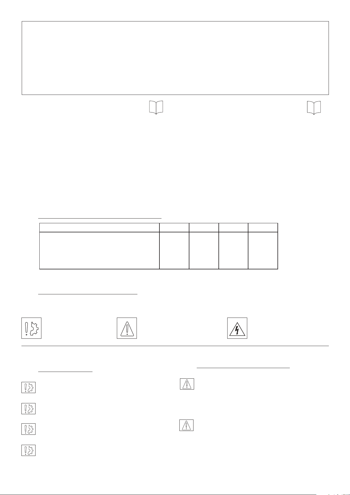
Fitting (Fig. 4)
Check that the brake is correctly set to the
nominal airgap. Tighten the M6 bolts in the
moving armature then fit the nut (see Fig. 4), then
fix the sensor using the M3 bolts and washers.
Magnet
Screw
washer M3
Moving
Armature
Nut
Switch
X
M5 screw
Fig. 4
Adjustment
Insert a shim 0,15 mm thick near to the bolt
between the face of the inductor and moving
armature. Switch the device on, tighten the bolt
to contact with the sensor until the switch point is
obtained then lock the bolt using the nut.
Warner Electric supply units provide protection
for coils and circuits. Where a brake is used
without our supply units, with switching on the
Check correct operation by making several
successive starts and releases.
DC, it is essential for the coil to be protected
against surges by a varistor fitted in parallel.
4 Warner Electric Europe • +33 (0)2 41 21 24 24 P-2060-WE • 2/13
Page 7

Switch Characteristics
Protection IP 40
Temperature: -40°C / +85°C
Switching power 5A - 250 VAC
Switch connection
Control position
Red
6.4 Accessories
Dust Cover – (555)
If you are using the brake in a clean environment
or it the surrounding atmosphere is loaded with
dust or humidity we recommend the use of a
dust cover.
Friction Disc Carrier – (312 or 315)
Black
Blue
2 positions
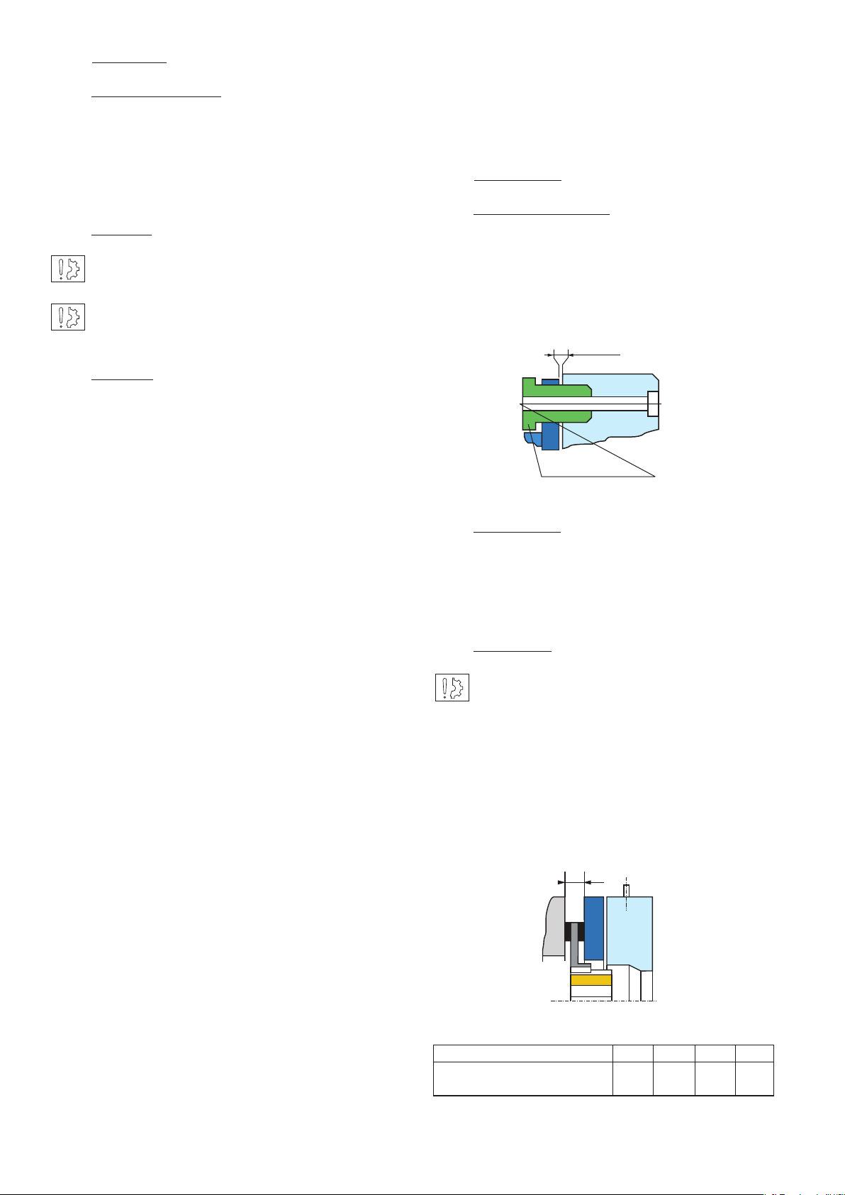
6.3 Hand release kit
Only for use with VAR02
Fitting (Fig. 5 and 6)
Check that the brake is correctly set to the
nominal airgap.
Washerscrew
Hand release
Axle
Spring
X
Fig. 5
Fit the bolts into the lever and through the inductor,
posi tion the springs in the moving armature, then
tighten nut as shown in Fig. 5, respecting dimension
X, see table 5.
Sizes 005 and 010 as standard are supplied with
a syn thetic version. On request, metallic version
for sizes 005 and 010 are also available.
Thick Friction Flange – (341)
If the mounting surface does not meet the
following specifications:
• cast iron or steel surface
• hardness 150 HB
• roughness 3,2 Ra (125 microinches)
• flatness 0,05 mm
then a thin or thick friction flange has to
be used.
Thin Friction Flange – (340)
This flange offers mounting at the inner diameter.
With the thin friction flange the mounting screws
are located at the outside.
Mounting Screw Kit – (913 or 914)
The short mounting screw kit supplied with
the thick flange is for mounting on the external
diameter threaded holes.
The long mounting screw kit supplied with the
thin flange is for mounting through the thin flange
on external diame ter or if ordered separately for
direct mounting without flange.
ERD Size 005 010 020 035
Dim. X (+0,2/0 mm) 111 1,5
Table 5
Removable
Handle
Fig. 6
Warner Electric Europe • +33 (0)2 41 21 24 24 P-2060-WE • 2/13 5
Page 8

7 Appendices
VAR00
7.1 ERD VAR00, VAR02
ERD VAR00
NO. Description
108 Mounted «DC» Magnet
312 Friction disc
315 Friction disc High Torque
515 Hub
551 Wedge
ERD VAR02
Airgap
551
312
315
515
108
VAR02
Airgap
551
NO. Description
108 Mounted «DC» Magnet
312 Friction disc
315 Friction disc High Torque
515 Hub
551 Wedge
7.2 Options
Options
NO. Description
340 Thin friction ange
341 Thick friction ange
418 Hand release kit
555 Dust cover
613 Detection kit
617 Connector kit
913 Set of short xing bolts
914 Set of long xing bolts
418
312
315
515
555
108
914
341
913
340
617
6 Warner Electric Europe • +33 (0)2 41 21 24 24 P-2060-WE • 2/13
613
Page 9

Electrically Release Brakes
ERD Sizes 060 to 300 & ERDD Sizes 120 to 600
Service Manual
P-2058-WE
SM321gb - rev 11/04
Page 10

We, WARNER ELECTRIC EUROPE, 7, rue Champfleur, B.P. 20095, F-49182 St Barthélemy d’Anjou Cedex
declare that the combined clutches and brakes are made in our factory from St Barthélemy d’Anjou,
and hereafter designated : EM and EMER
are exclusively designed for incorporation into a machine and to be assembled with other equipments to create a machine. The operation of
the product is submitted to the conformity of the complete equipment, following the provisions of the machinery directive 89/392/EEC and if
electric to the EMC directive 89/336 /EEC.
The conformity of the electric units to the Low Voltage directive 72/23 is supported by the full respect of the following standards : NFC 79300
and VDE 05808/8.65.
Drawn up in St Barthélemy d’Anjou, July 2002
E. PRAT, General Managing Director
CONTENTS
1 Technical specifications 2
2 Precautions and restrictions on use 2
2.1 Restrictions on use 2
2.2 Precautions and safety measures 2-3
3 Installation 3
3.1 Transport - storage 3
3.2 Handling 3
3.3 Installing 3
4 Maintenance 3
4.1 Adjusting the airgap 3
4.2 Maintenance 3
1 Technical specifications VAR00, VAR02
ERD Size 60 100 170 300
Nominal torque (STANDARD version) Nm
Nominal airgap +0,1/-0,05 mm
Pull-in airgap max. mm
Nominal torque (HIGH TORQUE version) Nm
Tightening torque of screws Nm
ERDD HT Size 120 200 340 600
Nominal torque (HIGH TORQUE version) Nm
Nominal airgap +0,1/-0,05 mm
Pull-in airgap max. mm
Tightening torque of screws Nm
4.3 Spare parts 4
5 Electrical connection 4
5.1 Important recommendations 4
5.2 Power supply 4
6 Options 4
6.1 Torque adjustment 4
6.2 Detection kit 5
6.3 Hand release kit 5
7 Appendices 6
7. 1 ERD VAR00 and VAR02 7
7.2 Options 7
60
0,3
0,8
80
24
160
0,3
0,8
24
100
0,3
0,9
130
24
260
0,4
0,9
24
170
0,3
0,9
220
24
440
0,4
0,9
24
300
0,3
1
400
48
800
0,4
1
48
Table 1
2 Precautions and restrictions on use
2.1 Restrictions on use
2.2 Precautions and safety measures
The equipment is designed for dry
running.
During maintenance, ensure that the Mechanism
to be braked by the equipment is at rest and
that there is no risk of accidental start-up.
Exceeding the maximum rotation speeds stated
in the catalogue invalidates the warranty.
The equipment can be fitted either horizontally or
vertically. The ERDD and HT version can only be
fitted horizontally.
All intervention have to be made by qualified
personnel, owning this manual.
Any modification made to the brake without
the express authorisation of a representative of
Warner Electric, in the same way than any use
out of the contrac tual specifications accepted by
This equipment is designed for an ambient
temperature of 40° maximum (155°C cladding
class).
2 Warner Electric Europe • +33 (0)2 41 21 24 24 P-2060-WE • 2/13
“Warner Electric”, will result in the warranty being
invalidated and Warner Electric will no longer be
liable in any way with regard to conformity.
Page 11

Symbol designating
an action that might
damage the brake
Symbol designating an
action that might be
dan gerous to human safety
Symbol designating an
elec trical action that might be
dangerous to human safety
3 Installation
3.1 Transport / storage
These units are delivered in packaging that
guarantees a 6 months storage period whether
transported by land, by air, or by sea to any
destination excepting tropical countries. (For
tropical destinations please consult Warner
Electric technical services).
3.2 Handling
Avoid any impacts on the equipment so as not
to alter their performance.
Never carry the equipment by the electrical
supply cable.
3.3 Installing
NB : ERD SZ060 to 300 brakes are supplied in
kit form. The Mounted inductor is supplied
airgap adjusted.
The ERDD HT brakes are delivered completely
mounted, the airgap is adjusted in our
workshop. See chapter 7 (appendix)
Do not grease the guiding splines (friction
disc / hub). It will change the brake’s
performances.
WATCH OUT ! Respect obligatory the direction
of the hub when mounting (see fig. 1 below)
ERD ERDD HT
Fig. 1
4 Maintenance
4.1 Adjusting the airgap
To adjust the airgap (Fig. 2), undo the adjustment
bolts in order to get the necessary value (see table
1). Check the value of the airgap at several points.
Make several motor manoeuvres stationary, then
again check the value of the airgap.
If a friction flange (341) is supplied, fix it first.
Put the key into the shaft then slide the hub
(515) onto the shaft and stop it axially by
suitable means.
Slide the friction disc (312) or (315) onto the
hub.
Fit the mounted inductor (107) or (108), remove
the wedge pieces (551) and fix it using the
fixing bolts (913) or (914).These screws have
to be tightened (see torque table 1). Secure the
bolts using a LOCTITE 270 type thermoplastic
liquid.
If a hand locking kit is supplied, it is preferable
to adapt it on the mounted inductor before the
inductor is fitted. (See chapter 6)
If a dust cover (555) is supplied, carefully slide it
onto the equipment before fitting it.
Switch the equipment on and confirm that the
friction disc rotates freely.
Make several motor manoeuvres stationary and
check the value of the airgap.
If the airgap is insufficient, refer to chapter 4
(maintenance)
Airgap
Adjusting screw
Fig. 2
ERD Size 060 100 170 300
E min (mm) 6 6 7,7 8
ERDD HT Size 120 200 340 600
E min (mm) 11,2 10 12,7 12,3
Table 2
4.2 Maintenance
Wear in the friction material causes an increase
in the air gap. Before reaching the maximum
airgap (see table 1), it is necessary adjust it (see
above).
Warner Electric Europe • +33 (0)2 41 21 24 24 P-2060-WE • 2/13 3
Page 12

4.3 Spare parts
After several adjustments, variable according
to size and use, it is necessary to replace the
friction disc (see Fig. 3 and table 2)
E
Fig. 3
To replace the friction disc(s) (312) or (315), undo
the fix ing bolts (913) or (914) then take off the
mounted induc tor (107) or (108) and then the
friction disc(s). Put the new friction disc(s) into
position then refit the mounted inductor and
adjust the airgap (see paragraph 4.1).
5 Electrical connection
ERD and ERDD HT brakes have to be supplied
with direct current and are factory fitted with
400 mm long wires. The polarity does not affect
operation.
5.1 Important recommendations
In the event of AC switching, the braking response
time may be multiplied by 6.
To get very short brake release and braking
times, we advise the CBC 140-5 (please ask):
• With overexcitation on brake release, the start
time can be divided by 3 (according to the
supply voltage)
• Adjusting the hold voltage to 50% of
the nominal voltage reduces the brake
engagement time and its temperature rise
Warner Electric supply units provide protection for
coils and circuits. Where a brake is used without
our supply units, with switching on the DC, it is
essential for the coil to be pro tected against
surges by a varistor fitted in parallel.
6 Options
6.1 Torque adjustment
Torque adjustment is only possible on VAR02 ( ~
50% of nominal torque).
Brakes are supplied adjusted to nominal torque.
Principle of torque reduction:
On VAR 02 (table 3), undo the adjustment ring
located at the rear of the inductor (see chapter
7).
All works on the electrical connections have to
be made with power off.
Ensure compliance with the nominal supply vol-
tage (inadequate supply causes a reduction in
the starting distance).
The connecting wires should be of sufficient
diameter to prevent voltage drops between the
source and equipment supplied.
I (A) / L (m) 0 to 10 m from 10 to 20 m
0 to 3 (A) 1,5 mm2 1,5 mm
3 to 6 (A) 1,5 mm2 2,5 mm
2
2
Tolerance for the supply voltage to the brake
terminals +5% / -10% (NF C 79-300).
5.2 Power supply
We advise the use of Warner Electric CBC 140
1, CBC 140-2 or CBC 140-5 supply units (with
overexcitation and holding voltage)
The supply and switching method has a great
influence on the response time. Response times
shown in our cat- alogues are for a supply at
nominal voltage with DC side switching.
STANDARD version
ERD Size 060 100 170 300
Nominal torque (Nm) 60 100 170 300
Max. number of turns
(adjustment ring)
Theoretical reduction in
torque for 1 turn of the
nut (Nm)
HIGH TORQUE version
ERD Size 060 100 170 300
ERDD Size 120 200 340 600
Nominal torque (Nm)
Max. number of turns
(adjustment ring)
Theoretical reduction in
torque for 1 turn of the
nut (Nm)
Table 3 (VAR02)
3 3 4,5 5,5
11 16 25 34
80 130 220 400
160 260 440 800
3 3 4,5 5,5
15 21 32 45
30 42 64 90
4 Warner Electric Europe • +33 (0)2 41 21 24 24 P-2060-WE • 2/13
Page 13

6.2 Detection kit
Fitting
6.3 Hand release kit
Only for use with VAR02
Magnet
Screw
washer M3
Moving
Armature
Nut
Switch
X
M5 screw
Fig. 4
Check that the brake is correctly set to the
nominal airgap. Tighten the M5 bolts in the moving
armature then fit the nut (see figure 4), then fix the
sensor using the M5 bolts and washers.
NB : The M3 fixing bolts are self tapping.
Adjustment
Insert a shim 0,15 mm thick near to the bolt
between the face of the inductor and moving
armature. Switch the device on, tighten the bolt
to contact with the sensor until the switch point
is obtained then lock the bolt using the nut.
Fitting: (Fig 5 and 6)
Check that the brake is correctly set to the
nominal airgap.
Washerscrew
Hand release
Axle
Spring
X
Fig. 5
Removable
Handle
Check correct operation by making several
successive starts and releases.
Switch characteristics
Protection IP 65
Temperature -40°C / +120°C
Cable 3 x 0,75 mm
Switching power: 8A-250VAC / 6A - 380 VAC
Switch connection
Control position
Red
Black
Blue
2 positions
Fig. 6
Fit the spindles in the lever, the springs in the
moving arma ture, then the bolts and washers as
shown in figure 5, res pecting dimension X (See
table 4)
ERD size 060 100 170 300
ERDD HT size 120 200 340 600
Dim. X (+0,2/0 mm) 111 1,5
Table 4
Warner Electric Europe • +33 (0)2 41 21 24 24 P-2060-WE • 2/13 5
Page 14

7 Appendices
7.1 ERD VAR00, VAR02
ERD VAR00
NO. Description
107 Mounted «AC» Magnet
108 Mounted «DC» Magnet
312 Friction disc
315 Friction disc High Torque
515 Hub
551 Wedge
Airgap
551
312
315
515
107
108
VAR00
ERD VAR02
NO. Description
107 Mounted «AC» Magnet
108 Mounted «DC» Magnet
312 Friction disc
315 Friction disc High Torque
515 Hub
551 Wedge
Airgap
551
312
315
515
107
108
VAR02
6 Warner Electric Europe • +33 (0)2 41 21 24 24 P-2060-WE • 2/13
Page 15

7.2 ERDD HT and options
ERDD HT
NO. Description
108 Mounted «DC» Magnet
312 Friction disc
315 Friction disc High Torque
320 Intermediate Disc
341 Thick Friction Flange
515 Hub
551 Wedge
914 Set of long Fixing Bolts
341 320
551
914
108
515
312
315
Options
NO. Description
339 Friction flange FERMG
341 Thick friction flange
418 Hand release kit
555 Dust Cover
613 Detection Kit
617 Connector Kit
913 Set of short xing bolts
914 Set of long xing bolts
555
617
339
418
341
914
913
613
Warner Electric Europe • +33 (0)2 41 21 24 24 P-2060-WE • 2/13 7
Page 16

Warranty
Warner Electric LLC warrants that it will repair or replace (whichever it deems advisable) any product manufactured and
sold by it which proves to be defective in material or workmanship within a period of one (1) year from the date of original
purchase for consumer, commercial or industrial use.
This warranty extends only to the original purchaser and is not transferable or assignable without Warner Electric LLC’s
prior consent.
Warranty service can be obtained in the U.S.A. by returning any defective product, transportation charges prepaid, to
the appropriate Warner Electric LLC factory. Additional warranty information may be obtained by writing the Customer
Satisfaction Department, Warner Electric LLC, 449 Gardner Street, South Beloit, Illinois 61080, or by calling 815-389-
3771.
A purchase receipt or other proof of original purchase will be required before warranty service is rendered. If found
defective under the terms of this warranty, repair or replacement will be made, without charge, together with a refund for
transportation costs. If found not to be defective, you will be notified and, with your consent, the item will be repaired or
replaced and returned to you at your expense.
This warranty covers normal use and does not cover damage or defect which results from alteration, accident, neglect, or
improper installation, operation, or maintenance.
Some states do not allow limitation on how long an implied warranty lasts, so the above limitation may not apply to you.
Warner Electric LLC’s obligation under this warranty is limited to the repair or replacement of the defective product and
in no event shall Warner Electric LLC be liable for consequential, indirect, or incidental damages of any kind incurred by
reason of the manufacture, sale or use of any defective product. Warner Electric LLC neither assumes nor authorizes any
other person to give any other warranty or to assume any other obligation or liability on its behalf.
WITH RESPECT TO CONSUMER USE OF THE PRODUCT, ANY IMPLIED WARRANTIES WHICH THE CONSUMER MAY
HAVE ARE LIMITED IN DURATION TO ONE YEAR FROM THE DATE OF ORIGINAL CONSUMER PURCHASE. WITH
RESPECT TO COMMERCIAL AND INDUSTRIAL USES OF THE PRODUCT, THE FOREGOING WARRANTY IS IN LIEU
OF AND EXCLUDES ALL OTHER WARRANTIES, WHETHER EXPRESSED OR IMPLIED BY OPERATION OF LAW OR
OTHERWISE, INCLUDING, BUT NOT LIMITED TO, ANY IMPLIED WARRANTIES OF MERCHANTABILITY OR FITNESS.
Some states do not allow the exclusion or limitation of incidental or consequential damages, so the above limitation or
exclusion may not apply to you. This warranty gives you specific legal rights and you may also have other rights which
vary from state to state.
Changes in Dimensions and Specications
All dimensions and specifications shown in Warner Electric catalogs are subject to change without notice. Weights do not
include weight of boxing for shipment. Certified prints will be furnished without charge on request to Warner Electric.
Warner Electric Europe
7 rue Champfleur, B.P. 20095, St Barthelemy d’Anjou - France
+33 (0)2 41 21 24 24 • Fax: +33 (0)2 41 21 24 70
www.warnerelectric.com
Printed in USAP-2060-WE • 2/13
 Loading...