

Page 1
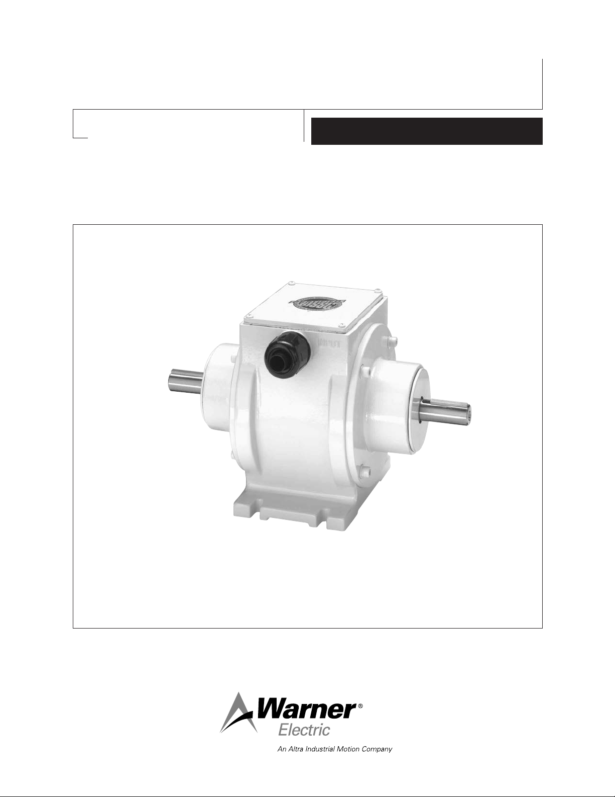
Washdown Electro-Packs EP-250-W, EP-400-W
Foot Mounted Clutch/Brakes
P-1510
819-0475
Installation Instructions
Page 2
Contents
Product Description
Product Description . . . . . . . . . . . . . . . . . . . . . 2
Installation Instructions . . . . . . . . . . . . . . . . . . . 3
Electrical Connections. . . . . . . . . . . . . . . . . . . . 3
Burnishing . . . . . . . . . . . . . . . . . . . . . . . . . . . . 3
Maintenance . . . . . . . . . . . . . . . . . . . . . . . . . . . 3
Servicing Worn Components . . . . . . . . . . . . . . 3
Troubleshooting . . . . . . . . . . . . . . . . . . . . . . . . 4
Clutch/Brake Selection Information
Horsepower vs. Shaft Speed . . . . . . . . . . . . 5
Part Numbers . . . . . . . . . . . . . . . . . . . . . . . 5
Mechanical Specifications . . . . . . . . . . . . . . 5
Electrical Coil Data . . . . . . . . . . . . . . . . . . . . 5
Dimensions . . . . . . . . . . . . . . . . . . . . . . . . . 5
Warranty . . . . . . . . . . . . . . . . . . . . . . Back Page
Failure to follow these
instructions may result in product damage,
equipment damage, and serious or fatal
injury to personnel.
Base Mounted Clutch/Brake Combinations
in a Rugged Washdown Housing
Meets electrical codes
UL Listed or CSA Certified.
The Washdown Electro-Pack (EP-W) is a
pre-assembled foot mounted clutch/brake
package complete with input and output shafts.
EP-Ws are specifically designed for applications
that require washing with high-pressure spray
systems. Their smooth exterior reduces the
accumulation of food particles or other
contaminants, which can cause bacteria growth.
They are coated with a USDA approved nontoxic
white paint that is extremely resistant to chipping
and corrosion. All fasteners, shafts, and keys are
made from stainless steel to prevent corrosion,
and the bearings are sealed and shielded to
prevent contamination during washdown.
EP-Ws are ready to be installed in all standard
power transmission systems using V-belts and
pulleys, chains and sprockets, in-line couplings,
timing belt drives, or gear trains.
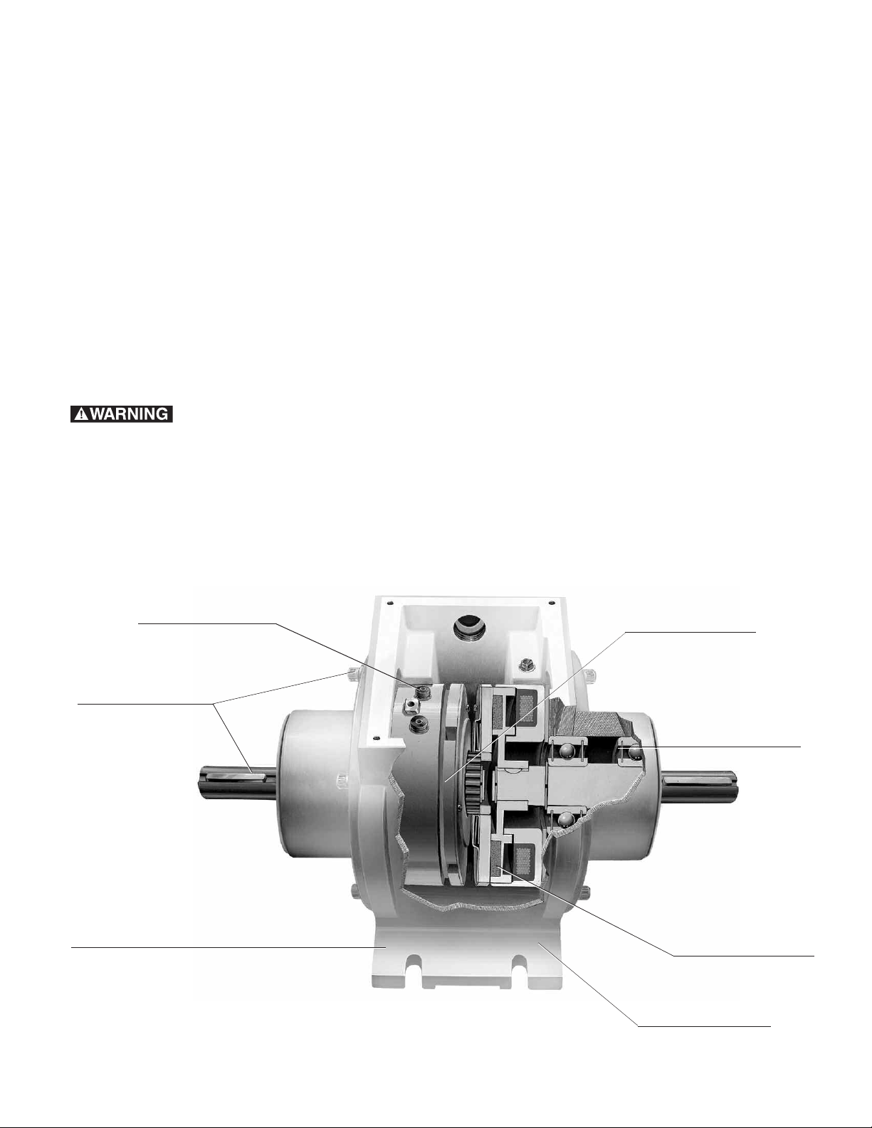
Pre-packaged
Over 20 major
components
have been pre-engi-
neered and pre-
assembled in a typical
Electro Pack. Ready-
to-go, straight from
the box.
Corrosion Resistant
Stainless steel shafts,
keys and fasteners.
Foot mounted
Bolt-it-down and wire-it-up. Allows for
quick replacement/reduced downtime.
Smooth exterior with USDA
Warner Electric • 800-825-9050 P-1510 • 819-0475
2
Heavy duty bearings
Sealed and shielded to
resist contamination.
Properly aligned for
maximum performance.
Maintenance free
Never needs lubrication.
Self-adjusting for wear of
clutch-brake friction faces.
Consistent performance.
BISSC Certified
approved white coating.
Page 3

Installation Instructions
C
C
B
B
Clutch/Brake
Control
DC
Vol t age
Clutch
Brake
AC
Vol t age
Input
Output
1. Review the selection procedure on page 5 to
determine if the selected Washdown
Electro-Pack (EP-W) is the appropriate size
and voltage for the intended application.
2. Identify the input end of the EP-W by locating
the word "INPUT" cast into the side of the
housing.
3. Mount the EP-W to a rigid surface that is flat
within the following tolerances. Position the
input end toward the intended drive system
input.
Electro-Pack Mounting Surface
Size Flatness
250 .004"
400 .004"
1. Remove the four screws and cover from the
top of the EP-W to gain access to the
electrical terminals on the clutch field and
brake magnet. (Figure 1)
2. Feed lead wires through one of the two 1/2"
conduit holes in the side of the EP-W housing.
3. Using the provided wire terminals, make the
proper electrical connections between the EPW and a suitable DC power supply. Refer to
Figure 2 for typical EP-W connections. Polarity
is not important when wiring Electro-Pack
units.
Warner Electric offers a full line of AC input, DC
output controls to meet the needs of most
clutch/brake applications. The service and
installation instructions included with each control
show the proper connections.
4. Attach the drive system hardware to the input
and output shafts of the EP-W. Be sure to
connect the power input to the input shaft of
the unit. Serious system damage may occur if
the power input is connected to the EP-W
output shaft. See page 5 for shaft
dimensions.
Electrical Connection
All electrical current must be
off when making electrical connections to
prevent injury or death which can result from
contact with live wires.
Figure 1
Warner Electric • 800-825-9050 P-1510 • 819-0475
Figure 2
4. Replace the cover and four screws.
Burnishing
To obtain optimum Electro-Pack performance, a
wear-in process called burnishing is required
between the clutch and brake friction faces within
the unit. Warner Electric Electro-Packs are
burnished at the factory, eliminating the need to
burnish the unit upon installation.
Maintenance
Properly applied and installed Electro-Packs do
not require service, lubrication, or maintenance.
The Washdown EP is designed to withstand
limited exposure to high ambient temperatures
and high-pressure wash systems, however
optimum appearance and wear life will be
obtained if this type of exposure is minimized.
3
Page 4

Servicing Worn Components
The normal wearing components of an ElectroPack are the brake magnet/armature, and the
clutch rotor/armature. Since special tools are
required to service these components, Warner
Electric does not recommend user service of the
Troubleshooting
Problem Possible Cause Correction
No or insufficient DC power
supplied to clutch or brake
coils.
Incorrect coil resistance.
Clutch or brake fails to engage.
Clutch or brake air gap out of
adjustment.
units. For more information contact your Warner
Electric distributor, or call Warner Electric at
1-800-234-3369.
Remove the EP-W cover, turn on the electrical power to the terminals, and
check the voltage across each pair of terminals. The voltage at the terminals
should be within 5% of the units rated voltage. If not, adjust or change the
power supply to obtain the rated voltage.
Remove the EP-W cover, disconnect the lead wires from the terminals on the
clutch and brake coils, and measure the resistance of each coil with an
appropriate ohmmeter. Both resistance measurements should be within 10%
of the values listed in the Electrical Specifications of this instruction sheet. If
not, replace the EP-W with a new unit.
Remove the EP-W cover, and inspect the gaps between the clutch rotor and
armature, and the brake magnet and armature. The gaps should be no larger
than .023" for EP-W-250's, and .037" for EP-W-400's. Adjust the gaps by
axially moving the appropriate armature until the gap is correct. Once set,
turn the clutch and brake power on and off to confirm that they engage, and
rotate the input and output shafts to confirm that the friction surfaces do not
drag when disengaged. Readjust if necessary.
Clutch or brake slips.
EP-W not properly sized for
intended application
Insufficient DC power supplied to clutch or brake coils.
Incorrect coil resistance.
Clutch or brake friction faces
contaminated.
Review the Selection Information page of this instruction sheet to determine
if the EP-W is properly sized for the application. For additional assistance,
contact your Warner Electric distributor or Warner Electric Technical Support
at 1-800-825-9050.
Remove the EP-W cover, turn on the electrical power to the terminals, and
check the voltage across each pair of terminals. The voltage at the terminals
should be within 5% of the units rated voltage. If not, adjust or change the
power supply to obtain the rated voltage.
Remove the EP-W cover, disconnect the lead wires from the terminals on the
clutch and brake coils, and measure the resistance of each coil with an
appropriate ohmmeter. Both resistance measurements should be within 10%
of the values listed in the Electrical Specifications of this instruction sheet. If
not, replace the EP-W with a new unit.
Remove the EP-W cover and inspect the clutch and brake friction faces for
contaminants. The friction surfaces should have a dry, polished appearance
with some dust present. If they are wet or oily they can be carefully cleaned
with a solvent, but optimum performance may never be achieved once the
faces are contaminated. If slipping persists after cleaning, replace the EP-W
with a new unit.
Warner Electric • 800-825-9050 P-1510 • 819-0475
4
Page 5

1/50
1/20
1/12
1/8
1/6
1/4
1/3
1/2
3/4
1
1-1/2
2
3
p p
HP
100
1000
200 300 400 500 600
700
800 900
110 0 12 00 15 00 18 00 2 000 24 00 3 000 36 00 40 00 45 00 5 000
SHAFT SPEED AT CLUTCH (IN RPM)
EP-250
EP-400
Clutch/Brake Selection Information
Output
A
B
C
D
H
E
G
F
E
D
C
B
Input
Brake
Clutch
O
M
N
L
K
J
I
Horsepower vs. Shaft Speed
Mechanical Specifications
Model Size DC 1800 RPM lb. in. Output Input RPM lbs.
EP-250 24
EP-400 24
Electrical Coil Data
Voltage – DC 24 90 24 90
Resistance @ 20˚ C – Ohms 76.4 1079 73 1087
Current – Amperes .314 .084 .332 .083
Watts 7.5 7.51 8.04 7.45
Coil Build up – milliseconds 48 44 154 154
Coil Decay – milliseconds 15 13 60 55
Build-up time equals current to approximately 90% of steady state value and flux to 90%. Decay time equals current to approximately 10% of
steady state value and flux to 10%. Values are approximate because current changes lead or lag flux changes by a small amount.
Selection Procedure
Determine the shaft speed at the Electro
Pack location. The number listed at the
intersection of horsepower and speed is
the size Electro Pack you require.
Part Numbers
Model Voltage
No. DC Part No.
EP-250 24 5130-273-060
90 5130-273-061
EP-400 24 5131-273-030
90 5131-273-031
Voltage Horsepower @ Static Torque Inertia–WR2(lb-in2) Max. Weight
90
90
1/2 70 .331 .293 7,500 7.1
1 270 2.566 2.222 4,500 19.7
EP-250-W EP-400-W
Clutch/Brake Clutch/Brake
Dimensions All dimensions are nominal, unless otherwise noted.
Size ABC Min. DEFG Max. HIJKLMNO
250-W 1/8 x .4995 1.250 2.468 3.312 2.250 8.968 .312 Wide 5.281 2.318 .375 1.625 3.250 4.250 1/2 - 14 NPT
1/8 x .4985 (4 slots) 2.308 conduit x 2
7/8 Dia.
400-W 3/16 x .7495 1.875 3.515 4.593 2.500 11.781 .312 Wide 6.937 3.474 .500 2.578 5.156 6.000 1/2 - 14 NPT
3/16 x .7485 (4 slots) 3.464 conduit x 2
1-3/8 Dia.
Warner Electric • 800-825-9050 P-1510 • 819-0475
5
Page 6

Warranty
Warner Electric LLC warrants that it will repair or replace (whichever it deems advisable) any
product manufactured and sold by it which proves to be defective in material or workmanship within a
period of one (1) year from the date of original purchase for consumer, commercial or industrial use.
This warranty extends only to the original purchaser and is not transferable or assignable without
Warner Electric LLC’s prior consent.
Warranty service can be obtained in the U.S.A. by returning any defective product, transportation
charges prepaid, to the appropriate Warner Electric LLC factory. Additional warranty information may
be obtained by writing the Customer Satisfaction Department, Warner Electric LLC, 449 Gardner
Street, South Beloit, Illinois 61080, or by calling 815-389-3771.
A purchase receipt or other proof of original purchase will be required before warranty service is
rendered. If found defective under the terms of this warranty, repair or replacement will be made,
without charge, together with a refund for transportation costs. If found not to be defective, you will be
notified and, with your consent, the item will be repaired or replaced and returned to you at your
expense.
This warranty covers normal use and does not cover damage or defect which results from
alteration, accident, neglect, or improper installation, operation, or maintenance.
Some states do not allow limitation on how long an implied warranty lasts, so the above limitation may
not apply to you.
Warner Electric LLC’s obligation under this warranty is limited to the repair or replacement of the
defective product and in no event shall Warner Electric LLC be liable for consequential, indirect,
or incidental damages of any kind incurred by reason of the manufacture, sale or use of any defective
product. Warner Electric LLC neither assumes nor authorizes any other person to give any other
warranty or to assume any other obligation or liability on its behalf.
WITH RESPECT TO CONSUMER USE OF THE PRODUCT, ANY IMPLIED WARRANTIES WHICH THE
CONSUMER MAY HAVE ARE LIMITED IN DURATION TO ONE YEAR FROM THE DATE OF ORIGINAL
CONSUMER PURCHASE. WITH RESPECT TO COMMERCIAL AND INDUSTRIAL USES OF THE
PRODUCT, THE FOREGOING WARRANTY IS IN LIEU OF AND EXCLUDES ALL OTHER
WARRANTIES, WHETHER EXPRESSED OR IMPLIED BY OPERATION OF LAW OR OTHERWISE,
INCLUDING, BUT NOT LIMITED TO, ANY IMPLIED WARRANTIES OF MERCHANTABILITY
OR FITNESS.
Some states do not allow the exclusion or limitation of incidental or consequential damages, so the
above limitation or exclusion may not apply to you. This warranty gives you specific legal rights and
you may also have other rights which vary from state to state.
Changes in Dimensions and Specifications
All dimensions and specifications shown in Warner Electric catalogs are subject to change without
notice. Weights do not include weight of boxing for shipment. Certified prints will be furnished without
charge on request to Warner Electric.
Warner Electric LLC
31 Industrial Park Road
815-389-3771
www.warnerelectric.com
An Altra Industrial Motion Company
P-1510 819-0475 06/11 Printed in USA
• Fax: 815-389-2582
• New Hartford, CT 06057
 Loading...