

Page 1
Gen 2
Spring-Set Brake Module
EM-50 ERS, EM-180 ERS
P-273-11
819-0533
Installation Instructions
An Altra Industrial Motion Company
Page 2
The Warner Electric Spring-Set Brake Module is designed to function as a holding brake for
NEMA C-face motors. The brake is self-engaging when the power is turned off or unintentionally
interrupted. It is to be mounted between a C-face motor and a C-face gear reducer. Do not apply
overhung or side loads to the output shaft of the Spring-Set Brake Module.
Failure to follow these instructions may result in product damage,
equipment damage, and serious or fatal injury to personnel.
Mounting the Brake to a Motor
1. Inspect the motor shaft and keyway for
burrs or damage. Remove all burrs and
repair damage so the brake module can
freely slide onto the shaft.
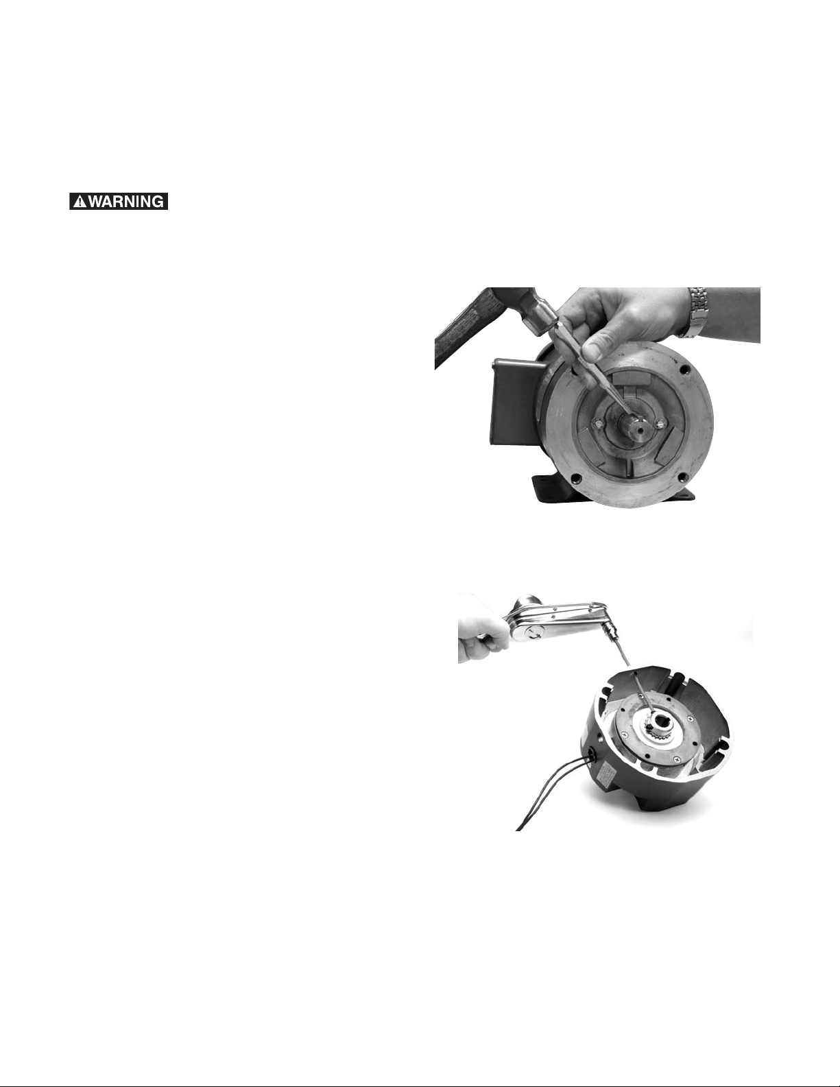
2. Insert the provided input key into the motor
shaft keyway. If necessary, prick punch the
motor shaft keyway to prevent the key from
sliding back while installing the brake
module. (Figure 1)
3. Remove the two plastic plugs with a
screwdriver to gain access to the hub
setscrews. Save these plugs to reinstall
after assembly is complete. The input hub
setscrews and the access holes in the
housing must be aligned to provide hex
wrench access for tightening to the motor
shaft. If they are not already aligned, apply
the rated voltage to the brake coil to release
the brake, and then rotate the shaft until the
setscrews and holes are aligned. (Figure 2)
4. Align the motor shaft and key with the brake
module keyway and slide the module onto
the motor shaft until the housing is in full
contact with the motor face. Do not use
excessive force. If the module does not
freely slide on, remove it and repair any
burrs or damage on the shaft.
Figure 1
Figure 2
Warner Electric • 800-825-9050 P-273-11 • 819-0533
2
Page 3

5. Rotate the brake housing to align the four (4)
mounting holes with the treaded holes in the
motor face. Secure the brake module to the
motor C-face with the four (4) mounting
tie-bolts alternately to ensure even alignment
of the module. Tighten them to 18-22 foot
pounds of torque. (Figure 3)
6. Tighten both input hub setscrews using a
torque wrench and long 5/32” Allen socket.
Tighten the two (2) setscrews to 80-85 inch
pounds of torque. Then replace the plugs
removed earlier. (Figure 4)
Mounting to a Gear Reducer
1. Warner Electric ERS modules are furnished
with a hardened key premounted on the
output shaft.
2. Align the module output shaft and key with
the reducer bore and keyway. Slide the
assembly together until the module and
reducer faces are in full contact. Do not use
excessive force.
Figure 3
3. Secure the module to the gear reducer
flange using four (4) 3/8-16, UNC-2A bolts
(typically furnished with the reducer.)
Tighten to 18-22 foot pounds of torque.
Electrical Connections
The brake module housing is threaded for
standard conduit connectors. The brake lead
wires are fed through this hole and are to be
connected to a DC power source with the same
voltage as that listed on the brake module label.
An optional conduit box kit can be purchased to
facilitate this connection (Warner part number
5370-101-042).
If a user provided DC power source is not
available, any of Warner Electric’s CBC-100,
CBC-150, or CBC-801 controls may be used
(selection based on user requirements). Refer to
the installation sheet included with the
control for connection information.
Figure 4
Warner Electric • 800-825-9050 P-273-11 • 819-0533
3
Page 4

Warranty
Warner Electric LLC warrants that it will repair or replace (whichever it deems advisable) any
product manufactured and sold by it which proves to be defective in material or workmanship
within a period of one (1) year from the date of original purchase for consumer, commercial or
industrial use.
This warranty extends only to the original purchaser and is not transferable or assignable without
Warner Electric LLC’s prior consent.
Warranty service can be obtained in the U.S.A. by returning any defective product, transportation
charges prepaid, to the appropriate Warner Electric LLC factory. Additional warranty information
may be obtained by writing the Customer Satisfaction Department, Warner Electric LLC, 449
Gardner Street, South Beloit, Illinois 61080, or by calling 815-389-3771.
A purchase receipt or other proof of original purchase will be required before warranty service is
rendered. If found defective under the terms of this warranty, repair or replacement will be made,
without charge, together with a refund for transportation costs. If found not to be defective, you will
be notified and, with your consent, the item will be repaired or replaced and returned to you at
your expense.
This warranty covers normal use and does not cover damage or defect which results from
alteration, accident, neglect, or improper installation, operation, or maintenance.
Some states do not allow limitation on how long an implied warranty lasts, so the above limitation
may not apply to you.
Warner Electric LLC’s obligation under this warranty is limited to the repair or replacement of the
defective product and in no event shall Warner Electric LLC be liable for consequential, indirect,
or incidental damages of any kind incurred by reason of the manufacture, sale or use of any
defective product. Warner Electric LLC neither assumes nor authorizes any other person to give
any other warranty or to assume any other obligation or liability on its behalf.
WITH RESPECT TO CONSUMER USE OF THE PRODUCT, ANY IMPLIED WARRANTIES WHICH
THE CONSUMER MAY HAVE ARE LIMITED IN DURATION TO ONE YEAR FROM THE DATE OF
ORIGINAL CONSUMER PURCHASE. WITH RESPECT TO COMMERCIAL AND INDUSTRIAL
USES OF THE PRODUCT, THE FOREGOING WARRANTY IS IN LIEU OF AND EXCLUDES ALL
OTHER WARRANTIES, WHETHER EXPRESSED OR IMPLIED BY OPERATION OF LAW OR
OTHERWISE, INCLUDING, BUT NOT LIMITED TO, ANY IMPLIED WARRANTIES OF
MERCHANTABILITY OR FITNESS.
Some states do not allow the exclusion or limitation of incidental or consequential damages, so the
above limitation or exclusion may not apply to you. This warranty gives you specific legal rights and
you may also have other rights which vary from state to state.
Changes in Dimensions and Specifications
All dimensions and specifications shown in Warner Electric catalogs are subject to change without
notice. Weights do not include weight of boxing for shipment. Certified prints will be furnished
without charge on request to Warner Electric.
Warner Electric LLC
449 Gardner Street • South Beloit, IL 61080
815-389-3771 • Fax: 815-389-2582
www.warnerelectric.com
P-273-11 • 819-0533 5/08 Printed in USA
An Altra Industrial Motion Company
 Loading...