

Page 1
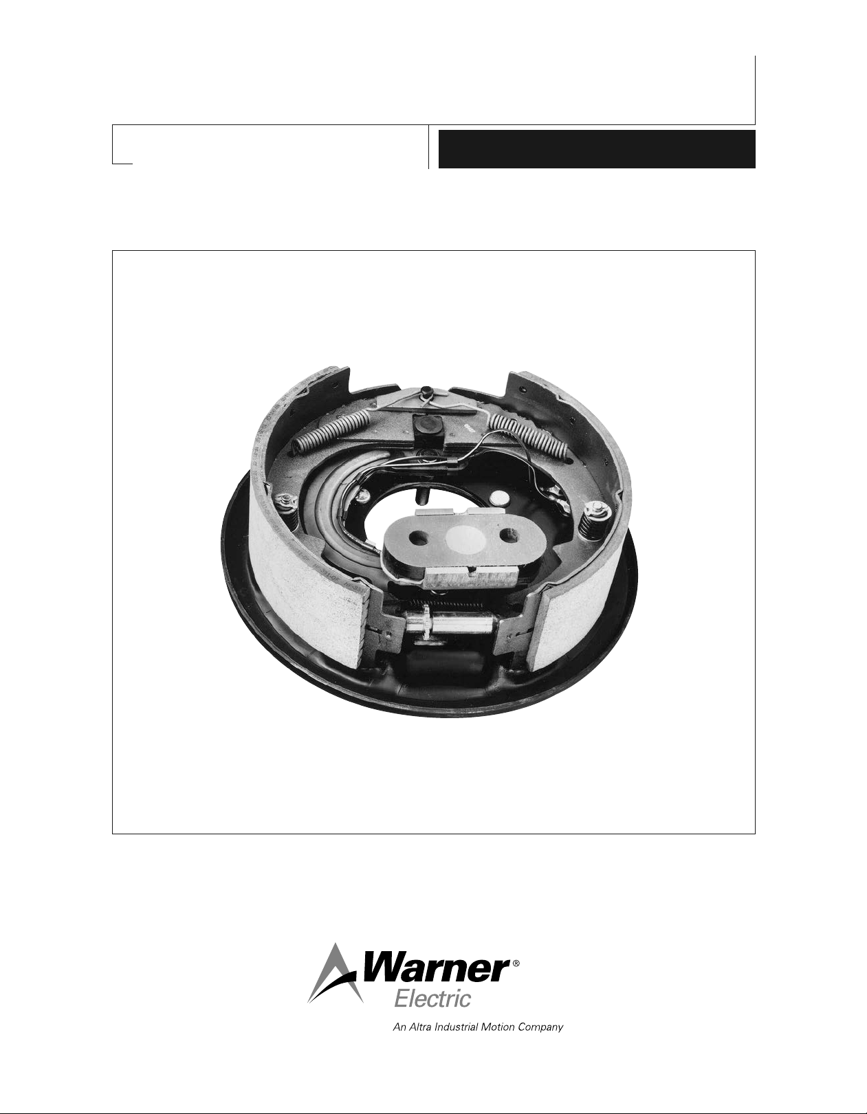
12-1/4" x 3-1/2" Electric Wheel Brake
A-216
819-0244
Installation Instructions
Page 2

A
A
˚
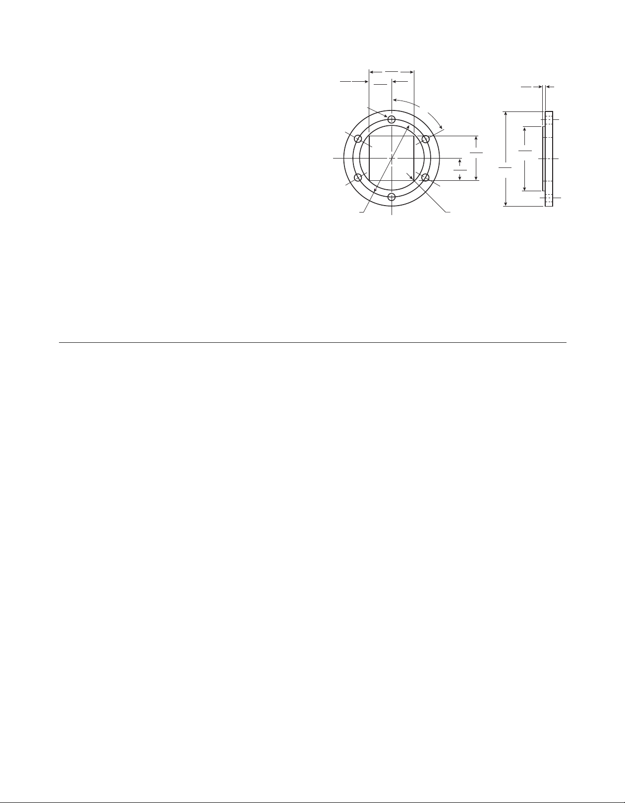
14 1/8 dia.
12.260
12.250
finished
drum dia.
4.510
4.503
pilot dia.
4.515
4.490
dia.
11.750
11.715
dia.
.290/.265 Dia. (6) holes equally spaced on
11.000 dia. within .007 R. of true position
(C'sunk for 1/4 dia. 80∞ flat head machine
screws with nuts and lockwashers, or 80∞ flat head rivets)
.170 min.
1/2–20 UNF-2A, (6) req'd.
Equally spaced on 5.500 dia. within
.005 R. of true position to
4.510/4.503 pilot diameter
.540
dia. min.
2.125
max.
Torque to
71-79 ft. lb.
4
3
1
2
1.100 min.
.125 ref.
.224
.205
3.881 min.
4.068 max.
4.381 min.
4.752 max.
3.567
3.507
12.225
12.195
factory adjustment diameter over brake linings
Face View of Brake Assembly
(Drum and armature removed)
(2) 1/4 dia. terminal studs
Section A–A
The magnet arm will
clear a maximum axle
of 3 1/2" diameter
or a 3" square
positioned as shown
Contents
Failure to follow these
instructions may result in product
Dimensions . . . . . . . . . . . . . . . . . . . . . . . . . . . .2
Technical Specifications . . . . . . . . . . . . . . . . . .3
Installation Instructions
General . . . . . . . . . . . . . . . . . . . . . . . . . . . . .3
Preparing the Brake Mounting Surface . . . . .3
Installing on Axle Flanges . . . . . . . . . . . . . . .3
Installing the Brake . . . . . . . . . . . . . . . . . . . .4
Preparing the Brake Drum . . . . . . . . . . . . . .4
Adjusting the Brake . . . . . . . . . . . . . . . . . . . .5
Installing the Trailer Brake Wiring . . . . . . . . .5
Replacement Parts . . . . . . . . . . . . . . . . . . . . . .6
Towing Products Required with your
12-1/4" x 3-1/2" Brakes
Controller . . . . . . . . . . . . . . . . . . . . . . . . . . .8
Load Control . . . . . . . . . . . . . . . . . . . . . . . . .8
Front Axle Resistor . . . . . . . . . . . . . . . . . . . .8
Warranty . . . . . . . . . . . . . . . . . . . . . . .Back Page
Dimensions when used with .224/.205 Armature, Warner Electric Part No. 110-0124
damage, equipment damage, and
serious or fatal injury to personnel.
Right hand brake shown
Left hand brake opposite
Drawing No. I-26117
Warner Electric • 800-825-9050 A-216 • 819-0244
2
Page 3
Technical Specifications
5.5 00
DIA . B.C.
.14 0 R. M ax.
60∞
.53 5
.52 5
DIA . (6) HOLES
EQU ALLY SPACE D.
LOC AT ED WIT HIN
.00 5 R. O F
TRU E POSI TION.
3.0 60
3.0 30
1.5 30
1.5 15
1.5 30
1.5 15
3.0 60
3.0 30
.14 0
.12 0
6.6 25
6.5 95
DIA
.
4.5 00
4.4 98
DIA .
Brake Rating – 7,500 lbs. to 10,000 lbs. axle
rated per pair. Based on an average retarding
torque which will produce a minimum of 43.5%
2
retardation, or 14 ft./sec.
mph initial velocity with 13.3 in. to 17.2 in. rolling
radius tires, with 10.8 volts at the magnets.
Mounting – 6 holes on 5.5" B.C.
Electrical – 12 Volt D.C. system only
Lining Area – 90 sq. in.
deceleration from 20
Drum Swept Area – 135 sq. in.
Lining Thickness – 5/16" nominal
Assembly Weight – 25 lbs. per brake
7 lbs. per armature
Note: Use with armature type drum only.
12-1/4" x 3-1/2" Utility Brake
Installation Instructions
The performance of your Warner Electric 12-1/4"
x 3-1/2" brake depends greatly on accurate
installation. Since proper installation helps to
assure long life and dependable performance,
please follow these installation instructions
carefully. Pay particular attention to drawing
I-26117 on page 2 of the manual.
General Instructions
The Warner Electric 12-1/4" x 3-1/2" utility
brake is designed for use with one-piece steel
armature number 110-0124, mounted inside
the brake drums.
For other possible combinations, please consult
your Warner Electric sales representative or
Warner Electric at 815-389-3771.
Warner Electric • 800-825-9050 A-216 • 819-0244
Axle Flange
Flanges available from a factory source.
A. Preparing the Brake Mounting Surface
Before installing the brake, check the
concentricity and squareness of the brake
drum to the hub and spindle. To do this,
mount the drum on the spindle according
to the manufacturer’s specifications.
The following tolerances must be held:
Drum friction surface concentric to spindle
centerline within .015-inch T.I.R. (Total Indicator
Reading).
Armature surface square to spindle within
.020-inch T.I.R.
B. Installing on Axle Flanges
1. The axle flange on which the brake mounts
must have a 4.500/4.498-inch pilot diameter.
2. This axle flange must be welded concentric
to the spindle within .015-inch T.I.R.
(measured at the pilot diameter). The axle
must be square to the spindle within
.010-inch T.I.R. (measured at the brake
mounting surface). Refer to drawing I-26117.
3
Page 4

C. Installing the Brake
Note: Brakes are designed as either right hand
or left hand assemblies by the RH or LH
marked on the outside of each backing plate.
(See Figure 1). The arrow on Figure 1 indicates
the direction of forward travel.
Figure 1 - Brake Designation
3. Tighten each of the six nuts with
lockwashers to 71-79 ft.-lbs. torque. Tighten
them alternately and evenly before applying
full torque (see Figure 3). Note that the pivot
pin also serves as a mounting stud.
Retorque the nuts after 50 miles of driving
and periodically thereafter.
4. After the brake has been mounted to the
flange, operate the lever arm to assure that it
moves freely.
1. Mount the brake to the axle flange with the
anchor pin at the top, the magnet at the
bottom, and the curve of the actuating lever
pointing toward the front of the trailer (see
Figure 2).
Front
of Trailer
Figure 2 - Mounting Position
2. Check to be sure that the brake backing
plate mates properly to the axle flange pilot.
The brake must be square with the spindle
when bolted into place.
Figure 3 - Tightening Nuts
D. Preparing the Brake Drum
Armature mounting holes are drilled in the brake
drum as indicated on the dimensional drawing
I-26117, page 2.
Warner Electric Armature P/N 110-0124
(.224/.205 thick)
a. Fasten this one-piece steel armature
inside the drum with (6) 1/4-inch
diameter flat head machine screws
with nuts and lockwashers (Step b)
or (6) 80° flat head rivets (Step c).
b. Fasten each machine screw with two
nuts tightened against one another to
prevent loosening. Peening the ends of
the screws is recommended as an
additional safeguard against loosening.
Warner Electric • 800-825-9050 A-216 • 819-0244
4
Page 5

c. Install the rivets according to the drum
manufacturer’s recommendations.
d. Install the brake drum according to the
manufacturer’s recommendations.
E. Adjusting the Brake
1. New brakes come pre-adjusted from the
factory and normally should not require
additional adjustment when mated with
new drums. The drum should, however,
be checked for freedom of rotation after
mounting. If dragging occurs, the brake
must be readjusted.
2. Brakes should always be readjusted when
they are installed with remachined drums.
Note: Brakes should never be installed in
used drums without remachining the drum
braking surface.
3. Follow these instructions to adjust the brake:
c. Back off the adjuster (downward motion
of the adjusting tool) until the wheel turns
freely, usually 4 to 5 notches on the
adjusting nut.
d. Replace the plug to keep out dirt and
moisture.
e. Brake readjustment is recommended after
the first 500 miles of operation (when
shoes and drums have been seated).
F. Installing the Trailer Brake Wiring
1. Wire the brakes in parallel according to the
wiring diagram (Figure 5).
2. Use good quality, insulated, crimp-type
connectors that fit 1/4-inch diameter
terminals to attach the wires to the brake.
3. Remove the top nut, and check that the
bottom nut remains tight.
a. Remove the adjuster plug located at
the bottom of the brake and insert an
adjusting tool (see Figure 4).
Figure 4 - Brake Adjustment
b. With the wheel off the ground, expand
the shoes until the brake drags
significantly. The shoes are expanded
by the upward motion of the adjusting
tool which turns the adjusting nut.
4. Install one connector over each 1/4-inch
stud terminal with a star washer under the
connector. Lock into place with the top nut.
Warner Electric • 800-825-9050 A-216 • 819-0244
5
Page 6

Figure 5 - Brake Wiring
BATT E RY
1110-41
FRONT AXLE
RESISTOR
TRAILER
FRONT REAR
GROUND WIRE
BRAKE
TRAILER PLUG
BREAKAWAY
SWITCH
NEGATIVE TERMINAL
Replacement Parts
All wearable parts are replaceable with factory
original components packed in convenient kits
complete with instruction sheets. These kits are
available through Warner Electric’s Distributor
Network.
Shoes & Linings/Shoe Hold Down Spring Kit
Kit No. 1301-100-005
Warner Electric • 800-825-9050 A-216 • 819-0244
6
Magnet Kit
Kit No. 1301-100-014
Shoe Return Spring Kit
Kit No. 1301-100-008
Page 7

Armature Kit
Kit No. 1301-100-013
Lever Arm Kit, L.H. Lever Arm Kit, R.H.
Kit No. 1301-100-016 Kit No. 1301-100-015
Terminal Accessory Kit
Kit No. 1301-100-011
Adjuster/Adjuster Spring Kit
Kit No. 1301-100-006
Mounting Accessory Kit
Kit No. 1301-100-003
Warner Electric • 800-825-9050 A-216 • 819-0244
7
Page 8

Towing Products Required with Your
12-1/4" x 3-1/2" Brakes
The following section, “Towing Products
Required with Your 12-1/4" x 3-1/2" Brakes,”
describes associated controls and components
necessary to complete your brake system
installation. Please read it carefully.
Controller
Warner Electric has one controller available
specifically for use with the 12-1/4" x 3-1/2"
brake. The Utility Controller, Warner Electric part
number 1300-76, is rated at 30 amps and 4, 6 or
8 brakes. This controller is designed to properly
synchronize the towing vehicle and trailer
brakes. Using other controllers may result in
excessive trailer brake torque causing jerky
braking and poor towing vehicle-to-vehicle
braking synchronization.
Load Control
The installation of 12-1/4" x 3-1/2" brakes on
any trailer which will operate with loads less than
rated capacity or with varying loads requires a
load control, Warner Electric part number
1300-78, to be installed in the towing vehicle.
The Warner Electric Load Control compensates
for trailer load variations by limiting the
maximum torque output of the brakes by adding
dropping resistance in the electrical control line.
When towing a trailer loaded to brake rated
capacity, the Load Control must be set at
maximum braking. When pulling an empty or
partially loaded trailer, the Load Control must be
set between maximum and minimum braking at
a position just before the point at which trailer
tire skidding occurs when actuating the hand
control fully on. Failure to install and use the
Warner Electric Load Control will result in
excessive brake torque when stopping a trailer
loaded to less than brake capacity.
Warner Electric’s Utility Controller has an
adjustment knob to control trailer brake torque.
Labeled “More” (braking power) and “Less”
(braking power), this adjustment does not affect
maximum braking capacity of the trailer brakes.
Because of the wide variety of towing vehicles
encountered, balancing towing vehicle brakes
and trailer brakes is necessary for smooth,
synchronized stops. To achieve this, the
controller adjustment should be set to provide
a slight lead in trailer braking over towing vehicle
braking. Turning the adjustment knob in the
“More” direction will increase the trailer brake
rate of application, while turning in the “Less”
direction will decrease the trailer brake rate of
application. When proper adjustment has been
achieved, there should be no sensation of the
trailer pushing or pulling the towing vehicle
during a stop. When this setting has been
reached, no further adjustment should be
required. For operating with varying load
weights, read the following section on “Load
Control.”
Front Axle Resistor
The Warner Electric Front Axle Resistor, part
number 1100-41, is designed to balance braking
forces between front and rear axle on two-axle
trailers. Utility trailers with tandem axle rocker
arm suspension present a typical application.
This suspension tends to transfer weight from
the front axle to the rear axle during braking,
allowing the front wheels to prematurely lock
and skid. By automatically reducing the current
flow, the Warner Electric Front Axle Resistor
reduces front axle braking forces to improve
brake balance, reduce tire wear, and minimize
the wheel lock-up.
Warner Electric • 800-825-9050 A-216 • 819-0244
8
Page 9

Warner Electric • 800-825-9050 A-216 • 819-0244
9
Page 10

Warranty
Warner Electric LLC warrants that it will repair or replace (whichever it deems advisable) any
product manufactured and sold by it which proves to be defective in material or workmanship within a
period of one (1) year from the date of original purchase for consumer, commercial or industrial use.
This warranty extends only to the original purchaser and is not transferable or assignable without Warner
Electric LLC’s prior consent.
Warranty service can be obtained in the U.S.A. by returning any defective product, transportation charges
prepaid, to the appropriate Warner Electric LLC factory. Additional warranty information may be obtained
by writing the Customer Satisfaction Department, Warner Electric LLC, 802 East Short Street, Columbia
City, Indiana 46725, or by calling 260-244-6183.
A purchase receipt or other proof of original purchase will be required before warranty service is
rendered. If found defective under the terms of this warranty, repair or replacement will be made, without
charge, together with a refund for transportation costs. If found not to be defective, you will be notified and,
with your consent, the item will be repaired or replaced and returned to you at your expense.
This warranty covers normal use and does not cover damage or defect which results from
alteration, accident, neglect, or improper installation, operation, or maintenance.
Some states do not allow limitation on how long an implied warranty lasts, so the above limitation may not
apply to you.
Warner Electric LLC’s obligation under this warranty is limited to the repair or replacement of the
defective product and in no event shall Warner Electric LLC be liable for consequential, indirect,
or incidental damages of any kind incurred by reason of the manufacture, sale or use of any defective
product. Warner Electric LLC neither assumes nor authorizes any other person to give any other warranty
or to assume any other obligation or liability on its behalf.
WITH RESPECT TO CONSUMER USE OF THE PRODUCT, ANY IMPLIED WARRANTIES WHICH THE
CONSUMER MAY HAVE ARE LIMITED IN DURATION TO ONE YEAR FROM THE DATE OF ORIGINAL
CONSUMER PURCHASE. WITH RESPECT TO COMMERCIAL AND INDUSTRIAL
USES OF THE PRODUCT, THE FOREGOING WARRANTY IS IN LIEU OF AND EXCLUDES ALL OTHER
WARRANTIES, WHETHER EXPRESSED OR IMPLIED BY OPERATION OF LAW OR
OTHERWISE, INCLUDING, BUT NOT LIMITED TO, ANY IMPLIED WARRANTIES OF
MERCHANTABILITY OR FITNESS.
Some states do not allow the exclusion or limitation of incidental or consequential damages, so the above
limitation or exclusion may not apply to you. This warranty gives you specific legal rights and you may also
have other rights which vary from state to state.
Changes in Dimensions and Specifications
All dimensions and specifications shown in Warner Electric catalogs are subject to change without notice.
Weights do not include weight of boxing for shipment. Certified prints will be furnished without charge on
request to Warner Electric.
Warner Electric
802 East Short Street • Columbia City, IN 46725
260-244-6183 • Fax: 260-244-3928
www.warnerelectric.com
A-216 • 819-0244 8/11 Printed in USA
An Altra Industrial Motion Company
 Loading...