

Page 1
P-2035-WE
SM309-gb-11/04
Electromagnetic
Toothed Clutch E320
Service Manual
Page 2
We: WARNER ELECTRIC EUROPE, 7, rue Champfleur, B.P. 20095, F-49182 St Barthélemy d’Anjou Cedex declare
We, WARNER ELECTRIC EUROPE, 7, rue Champfleur, B.P. 20095, F-49182 St Barthélemy d’Anjou Cedex
declare that the clutches made in our factories from St Barthélemy d’Anjou,
and hereafter designated: E320
are exclusively designed for incorporation into a machine and to be assembled with other equipments to create a machine. The operation of the
product is submitted to the conformity of the complete equipment, following the provisions of the machinery directive 98/37/EC and if electric to
the EMC directive 89/336 /EEC.
The conformity of the electric units to the Low Voltage directive 72/23 (mofified) is supported by the full respect of the following standards :
NFC 79300 and VDE 05808/8.65.
Drawn up in St Barthélemy d’Anjou, July 2002
E. PRAT, General Managing Director
CONTENTS
1Technical specifications 2
2 Precautions and restrictions on use 2
2.1 Restrictions on use 2
2.2 Precautions in use 3
and safety measures
3Installation 3
3.1 Transport - storage 3
3.2 Handling 3
3.3 Installing 3
3.3.1 Installing VAR00/04/10/14 3
3.3.2 Installing VAR504 3
3.3.3 Installing VAR05 4
4Maintenance 4
5Electrical connection 4
5.1 Important recommendations 4
5.2 Power supply 4
6 Appendix 5
6.1 Drawings / Part numbers 6
that the clutches made in our factories from St Barthélemy d’Anjou, and hereafter designated : E320
are exclusively designed for incorporation into a machine and to be assembled with other equipments to create a machine. The operation of the
product is submitted to the conformity of the complete equipment, following the provisions of the machinery directive 98/37/EC and if electric to the
EMC directive 89/336 /EEC.
The conformity of the electric units to the Low Voltage directive 72/23 (modified) is supported by the full respect of the following standards : NFC
79300 and VDE 05808/8.65.
Drawn up in St Barthélemy d’Anjou, july 2002 E.
PRAT, General Managing Director
CONTENTS
1 Technical specifications 2
2 Precautions and restrictions on use 2
2.1 Restrictions on use 2
2.2 Precautions in use 3
and safety measures
3 Installation 3
3.1 Transport - storage 3
3.2 Handling 3
3.3 Installing 3
1Technical specifications
Size 20 50 100 200 400 800 1600
N max. VAR00 min
N max. VAR04/05 min
Dimension J
Weight VAR04/10/14 kg 1 1.2 2 3 4 7 14
±0.1
-1
5000 5000 4300 3600 3300 2700 2100
-1
- 3900350028002600 2100 1500
mm 0.3 0.4 0.5 0.5 0.5 0.6 0.7
3.3.1 Installing VAR00/04/10/14 3
3.3.2 Installing VAR504 3
3.3.3 Installing VAR05 4
4 Maintenance 4
5 Electrical connection 4
5.1 Important recommendations 4
5.2 Power supply 4
6 Appendix 5
6.1 Drawings / Part numbers 5-6
Coupling - - 28/38 38 42 48 55 75
Dimension E VAR05 mm - 20
+1.5/0
24
+1.8/0
26
+2/0
28
+2.1/0
30
+2.2/0
Weight VAR05 kg - 2,5 4.5 6.8 8.3 15.5 31
Size 3200 6400 12800 25600
N max. VAR00 min
N max. VAR04/05 min
Dimension J
±0.1
Weight VAR04/10/14 kg 29.5 82 145 254
Coupling - 90 125 - Dimension E VAR05 mm 45
Weight VAR05 kg 61 161 - -
NB: Data for catalogue equipment.
-1
1800 1500 1500 1200
-1
1400 1000 - -
mm 0.8 1 1 1
+3.4/0
+4.6/0
60
--
Table 1
40
+3/0
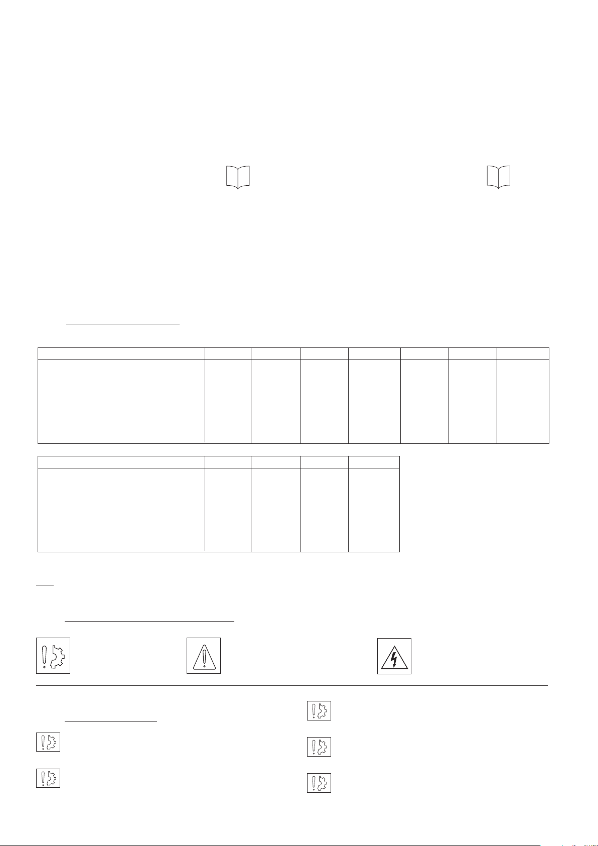
2 Precautions and restrictions on use
Symbol designating
an action that might
damage the brake
Symbol designating an action
that might be dan gerous to
human safety
Symbol designating an
elec trical action that might be
dangerous to human safety
Exceeding the maximum rotation speed listed
2.1 Restrictions on use
VAR00/10 units are designed for operation in
oil (not sealed bearings).
VAR04/14 and VAR05 are designed for dry
operation (sealed bearings).
in the catalogue will invalidate the guarantee.
The suitable ambient temperature for these
units is max. 40°C (Insulation class of 155°C).
E320 clutches are designed for horizontal
mounting. Consult our technical services if other
mounting positions are required.
2 Warner Electric Europe • +33 (0)2 41 21 24 24 P-2035-WE • 2/13
Page 3
2.2 Precautions in use and safety measures
During maintenance, ensure that the machine’s
moving parts are stationary and that there is no
risk of accidental start-up. All intervention have to be
made by qualified personnel, owning this manual.
0,25 0,25
1
Any modification made to the brake without
the express authorisation of a representative
of Warner Electric, in the same way than any use out
of the contrac tual specifications accepted by “Warner
Electric”, will result in the warranty being invalidated
and Warner Electric will no longer be liable in any way
with regard to conformity.
3 Installation
3.1 Transport / storage
Our clutches and brakes are supplied in packaging
guar anteeing a preservation period of 6 months with
land or air transport, or after transport by ship to
neighbouring conti nents (without crossing the tropics).
3.2 Handling
Avoid any impacts on the equipment so as not
to alter their performance.
Never carry the equipment by the electrical
supply cable.
Fig. 1
3.3.1 Installing VAR00/VAR04/VAR10/VAR14
• Center the mobile toothed ring assembly (352) or the
mobile plate (353) on the driven part, then fix it
with screws and lock them
• After adjusting the driving key, mount inductor on
the shaft and fix it axially onto the shaft
It is important to tighten the locking screws from
mobile toothed assembly to the specified torque
(see table 2) or to the mobile plate (353) and secure
them with loctite 243 or an equivalent product.
While assembling the driving and driven parts,
it is essential to note the value J (which is the
distance between tooth heads), see Table 1.
3.3.2 VAR504
3.3 Installing
E320 are delivered with bore / tolerance H7 and keyway/
tolerance P9 according to NFE22175 / DIN6885 /
ISO R773 / BS 4235. The mobile plate assembly (353)
is delivered with bore / tolerance H7. We recommand to
use tolerance h6 for shaft and g6 for the mobile toothed
ring assembly (352).
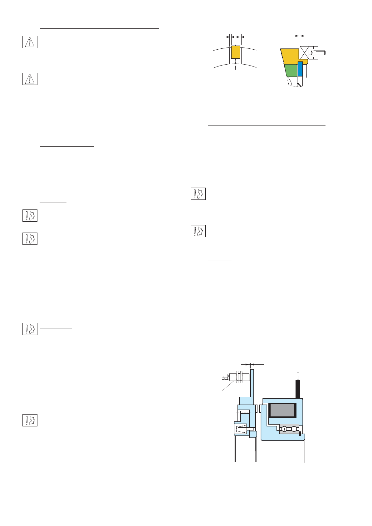
Important: It is important to prevent inductor
(101) from rotating. It is the customers
responsibility to supply means to prevent inductor
rotating. i.e. retention pin in slot.Check gaps between
the inductor and the retention pin (see Figure 1) :
minimum 0,5 mm gap -1 mm gap at the slot bottom.
The pin should not generate any stress on the bearings.
In case of vibrations, it is strongly recommended to
insert a damping elastic slot between the anti-rotation
device and the anti-rotation slot and to fix the coil’s
cable the nearest of it to avoid whipping.
In the case where two co-axial shafts are
fitted, the recommended setover is 0,05 mm
maximum.
The angular misalignment should not be greater than
0,1 mm over a length of 100 mm. If this is the case,
use a VAR05 (flexible coupling).
Detection discs (aluminium or steel) compatible with
induc tive proximity sensor are provided with unit.
The position of the sensor should not obstruct the
travel of the toothed flange (352) (353).
We suggest to use the inductive sensor (615) provided
by our company, (see technical form).
MOUNTING EXAMPLE
Airgap
Sensor
Warner Electric Europe • +33 (0)2 41 21 24 24 P-2035-WE • 2/13 3
Page 4

3.3.3 Installing VAR05
5 Electrical connection
• After adjusting the driving key, mount the inductor
onto the shaft, then fit the adjusting spacer (526) and
the bearing assembly and finally lock the whole axially
on the shaft.
Sizes 3200 and 6400 : the coupling flange (528) is not
mounted in our workshops. After mounting the u to
thshaft, fit the flange with the screws provided to the
spe cified torque (see Table 2) and secure them with
Loctite 243 or equivalent.
Size 3200 6400
Screws M12 M16
Tightening torque 76 ± 8 Nm 189 ± 18 Nm
Table 2
NB.: VAR05 is delivered with a pre-adjusted airgap.
However check the value J between tooth heads after
mounting. (see Table 1).
E320 units must be supplied with direct current (D.C)
and are equipped with a 500 mm length wire. Polarity
does not affect the functioning.
5.1 Important recommendations
All works on the electrical connections have to
be made with power off.
Ensure compliance with the nominal supply voltage
(inade quate supply causes a reduction in the starting
distance and transmissible torque).
The connecting wires should be of sufficient diameter
to prevent voltage drops between the source and
equipment supplied.
I (A) / L (m) 0 to 10 m from 10 to 20 m
0 to 3 (A) 1,5 mm2 1,5 mm
3 to 6 (A) 1,5 mm2 2,5 mm
2
2
Tolerance in the supply voltage to the clutch terminals
+5% / -10% (NF C 79-300).
• Mount the coupling hub (507) onto the second
shaft and lock it axially
• Put the spider (730) inside the coupling flange (528)
• Assemble the driving part with the driven part and
insert the coupling hub with the spider (730)
While mounting the unit, it is essential that you
note value E (elastic coupling mounting),
see Table 1.
4 Maintenance
After continued operation it may become necessary to
change bearings. The inductor bearings are mounted
in a special way, and we recommend returning the unit
back to the factory for replacement.
5.2 Supply
For controlling these clutches, we advise the use of
Warner Electric supply units
Sizes 20 to 3200:
CBC 400-24, CBC450-24
CBC 140-5
Sizes 6400 to 12800:
CBC 140-5
Warner Electric supply units provide protection for coils
and circuits. Where a clutch is used without our supply
units, with switching on the DC, it is essential for the
coil to be protected against surges by a varistor fitted
in parallel.
4 Warner Electric Europe • +33 (0)2 41 21 24 24 P-2035-WE • 2/13
Page 5

6 Appendix
6.1 Drawings / Part numbers
210
352
VAR00 / 04 / 10 / 14
Sizes 20 to 3200
617
J
101
803
949
210
353
VAR00 / 04 / 10 / 14
Sizes 6400 to 25600
351
350
617
101
803
949
Nr Description
101 Magnet
210 Driving hub
350 Bronze toothed rim
351 Steel toothed rim
352 Mobile toothed ring assembly
353 Mobile plate assembly
507 Coupling hub
526 Spacer adjustment
528 Coupling flange
730 Spider
801 Ball bearings
803 Centering ball bearing
949 Outside retainer
615 Inductive proximity sensor
617 Connector kit
526
210
803
949
617
352
101
E320 VAR04
VAR05
E
730528801
507
Warner Electric Europe • +33 (0)2 41 21 24 24 P-2035-WE • 2/13 5
Page 6

6.1 Drawings VAR504
L (Disengaged)
E
L (Disengaged)
E
Size
20-3200
A
B
INDUCTIVE PROXIMITY SENSOR
615
M12 x 1
17 on flat
35
A
LED
Brown
Load
Black
Blue
Size
6400-25600
+
–
Sizes 50 100 200 400 800 1600 3200 6400 12800 25600
A 135 152 168 178 205 250 288 400 465 540
B 88 104 120 132 158 205 235 ––-
E 3333333555
L 12 14 15,5 16 20,5 28 40 37,5 42 59,5
CHARACTERISTICS
Rate operating distance (steel target) 2 mm
Monting shilded
Switching element function Normally open
Cable NPN, 3 x 0,34 mm2, 2 m
Usable supply voltage 18 V... 30 VDC
Ripple voltage ≤ 10 %
No load supply voltage ≤ 10 mA
Rated operational current 120 mA
Voltage drop ≤ 1,5 V
Off-state current ≤ 10 µA
Short circuit protection yes
Overload protection yes
6 Warner Electric Europe • +33 (0)2 41 21 24 24 P-2035-WE • 2/13
Reverse battery protection yes
Wire break resistance yes
EMC Group A
Operating frequency 2000 Hz
Hysteresis≤ 15 %
Temperature drift≤ 10 %
Repeat accuracy≤ 10 %
Housing Nickel-plated brass
Front cap PBTP
Degree of protection (EN 60529) IP 67
Ambiant air temperature –25°C... +70°C
Page 7

Warranty
Warner Electric LLC warrants that it will repair or replace (whichever it deems advisable) any product manufactured and
sold by it which proves to be defective in material or workmanship within a period of one (1) year from the date of original
purchase for consumer, commercial or industrial use.
This warranty extends only to the original purchaser and is not transferable or assignable without Warner Electric LLC’s
prior consent.
Warranty service can be obtained in the U.S.A. by returning any defective product, transportation charges prepaid, to
the appropriate Warner Electric LLC factory. Additional warranty information may be obtained by writing the Customer
Satisfaction Department, Warner Electric LLC, 449 Gardner Street, South Beloit, Illinois 61080, or by calling 815-389-
3771.
A purchase receipt or other proof of original purchase will be required before warranty service is rendered. If found
defective under the terms of this warranty, repair or replacement will be made, without charge, together with a refund for
transportation costs. If found not to be defective, you will be notified and, with your consent, the item will be repaired or
replaced and returned to you at your expense.
This warranty covers normal use and does not cover damage or defect which results from alteration, accident, neglect, or
improper installation, operation, or maintenance.
Some states do not allow limitation on how long an implied warranty lasts, so the above limitation may not apply to you.
Warner Electric LLC’s obligation under this warranty is limited to the repair or replacement of the defective product and
in no event shall Warner Electric LLC be liable for consequential, indirect, or incidental damages of any kind incurred by
reason of the manufacture, sale or use of any defective product. Warner Electric LLC neither assumes nor authorizes any
other person to give any other warranty or to assume any other obligation or liability on its behalf.
WITH RESPECT TO CONSUMER USE OF THE PRODUCT, ANY IMPLIED WARRANTIES WHICH THE CONSUMER MAY
HAVE ARE LIMITED IN DURATION TO ONE YEAR FROM THE DATE OF ORIGINAL CONSUMER PURCHASE. WITH
RESPECT TO COMMERCIAL AND INDUSTRIAL USES OF THE PRODUCT, THE FOREGOING WARRANTY IS IN LIEU
OF AND EXCLUDES ALL OTHER WARRANTIES, WHETHER EXPRESSED OR IMPLIED BY OPERATION OF LAW OR
OTHERWISE, INCLUDING, BUT NOT LIMITED TO, ANY IMPLIED WARRANTIES OF MERCHANTABILITY OR FITNESS.
Some states do not allow the exclusion or limitation of incidental or consequential damages, so the above limitation or
exclusion may not apply to you. This warranty gives you specific legal rights and you may also have other rights which
vary from state to state.
Changes in Dimensions and Specications
All dimensions and specifications shown in Warner Electric catalogs are subject to change without notice. Weights do not
include weight of boxing for shipment. Certified prints will be furnished without charge on request to Warner Electric.
Warner Electric Europe
7 rue Champfleur, B.P. 20095, St Barthelemy d’Anjou - France
+33 (0)2 41 21 24 24 • Fax: +33 (0)2 41 21 24 70
www.warnerelectric.com
P-2035-WE • 2/13
Warner Electric Europe • +33 (0)2 41 21 24 24 P-2035-WE • 2/13 7
Printed in USA
 Loading...