

Page 1
P-2033-WE
SM307-gb-11/04
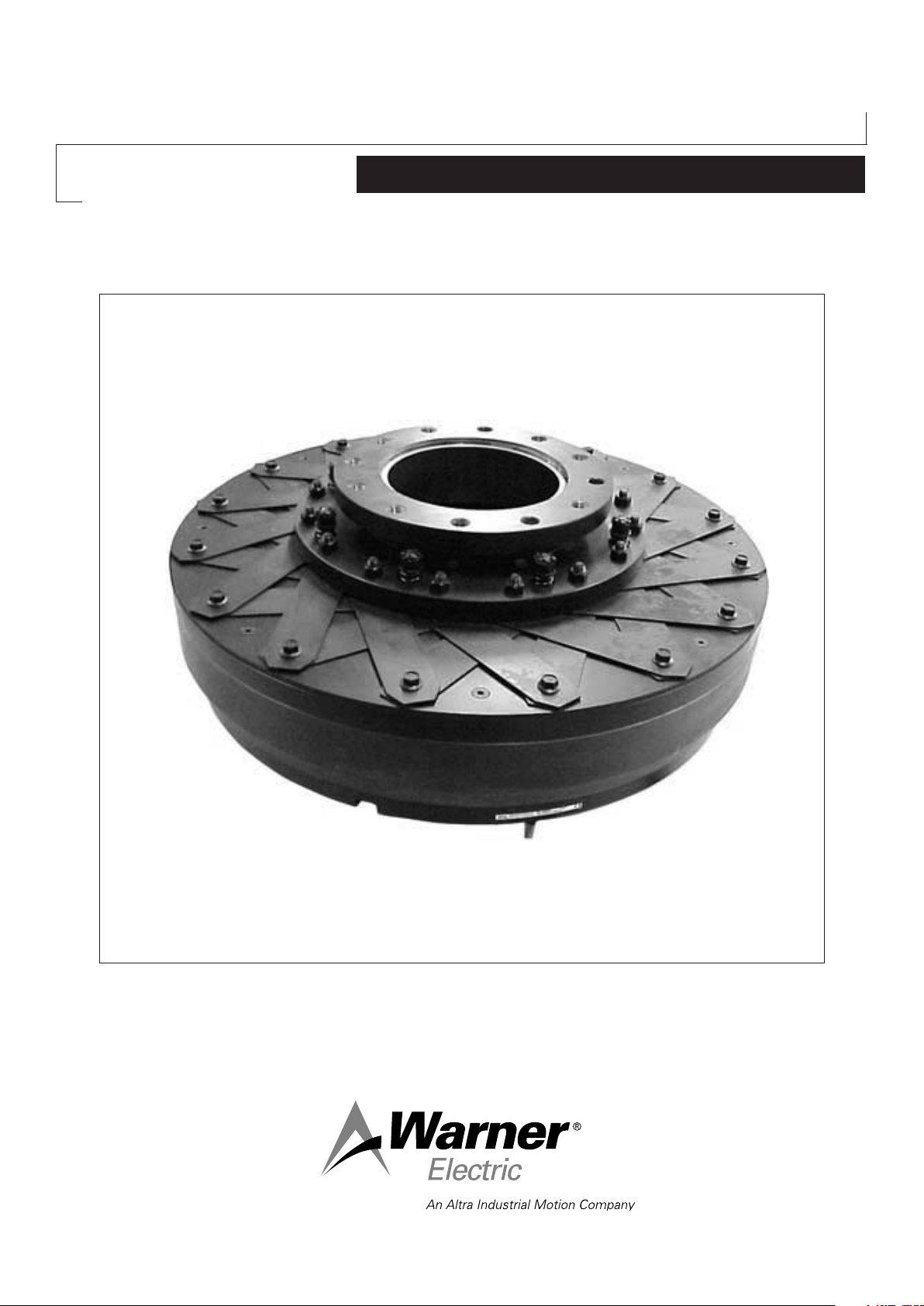
Electromagnetic Single Disc
Clutches E210 and E220
Service Manual
Page 2
We: WARNER ELECTRIC EUROPE, 7, rue Champfleur, B.P. 20095, F-49182 St Barthélemy d’Anjou Cedex
declare that the clutches made in our factories from St Barthélemy d’Anjou,
and hereafter designated : E210 and E220
are exclusively designed for incorporation into a machine and to be assembled with other equipments to create a machine. The operation of the
product is submitted to the conformity of the complete equipment, following the provisions of the machinery directive 98/37/EC and if electric to
the EMC directive 89/336 /EEC.
The conformity of the electric units to the Low Voltage directive 72/23 (modified) is supported by the full respect of the following standards :
NFC 79300 and VDE 05808/8.65.
Drawn up in St Barthélemy d’Anjou, july 2002
E. PRAT, General Managing Director
CONTENTS
1Technical specifications 2
2 Precautions and restrictions on use 2
2.1 Restrictions on use 2
2.2 Precautions 2
and safety measures
3Installation 3
3.1 Transport - storage 3
3.2 Handling 3
3.3 Installing 3
3.3.1 Installing VAR00 and VAR02 3
3.3.2 Installing VAR05 4
4Maintenance 4
4.1 Maintenance 4
4.2 Spare parts 4
5Electrical connection 5
5.1 Important recommendations 5
5.2 Power supply 5
6 Appendix 6
1Technical specifications
We: WARNER ELECTRIC EUROPE, 7, rue Champfluer, B.P. 20095, F-49182 St Barthélemy d’Anjou Cedex declare that the clutches made in our
factories from St Barthélemy d’Anjou,
and hereafter designated: E210 and E220
are exclusively designed for incorporation into a machine and to be assembled with other equipments to create a machine. The operation of the
product is submitted to the conformity of the complete equipment, following the provisions of the machinery directive 98/37/EC and if electric to the
EMC directive 89/336/EEC.
The conformity of the electric units to the Low Voltage directive 72/23 (modified) is supported by the full respect of the following standards: NFC
79300 and VDE 05808/8.65.
Drawn up in St Barthélemy d’Anjou, july 2002
E. PRAT, General Managing Director
CONTENTS
1 Technical specifications 2
2 Precautions and restrictions on use 2
2.1 Restrictions on use 2
2.2 Precautions 2
and safety measures
3 Installation 3
3.1 Transport - storage 3
3.2 Handling 3
3.3 Installing 3
1 Technical specifications
Size 200 400 800 1600 3200 6400 12800
N max. (VAR00) tr/min 2600 2000 1700 1500 1500 - N max. (VAR02) tr/min - 3000 2500 2200 1800 1500 1500
Travel P mm 0.5
±0.1
0.5
±0.1
Max. travel mm 1 1.2 1.4 1.7 1.8 2.2 2.8
Coupling 55 65 75 90 100 125 180
Dimension E VAR05 mm 30
+2.20/0
35
+2.6/0
Flange-screws (528) (VAR05) M8 x 20 M8 x 20 M10 x 25 M12 x 25 M16 x 25 M16 x 40 M20 x 40
Tightening torque Nm 22
±2
22
±2
3.3.1 Installing VAR00 and VAR02 3
3.3.2 Installing VAR05 4
4 Maintenance 4
4.1 Maintenance 4
4.2 Spare parts 4
5 Electrical connection 5
5.1 Important recommendations 5
5.2 Power supply 5
6 Appendix 6
0.6
40
44
±0.1
+3/0
±4
0.8
45
76
±0.1
+3.6/0
±8
0.8
+3.6/0
50
189
±0.1
±18
1
+4.6/0
60
189
±0.1
±18
Weight (VAR00, 02) kg 20 25,5 35,2 61 122 220 380
Weight (VAR05) kg 27,4 31,5 50,5 85,5 158 298 597
NB : data for catalogue equipment
NB : data for catalogue equipment
2 Precautions and restrictions on use
2.1 Restrictions on use
This equipment is designed for dry running.
Any oily material alters performance.
Exceeding the maximum speed of rotation
stated in the catalogue invalidates the warranty.
Table 1
2.2 Precautions in use and safety measures
During maintenance, ensure that the machine’s
moving parts are stationary and that there is no
risk of accidental start-up. All intervention
have to be made by qualified personnel,
owning this manual.
1
85
370
±0.1
+6.4/0
±37
This equipment is designed for a maximum
ambient temperature of 40° (155°C casing
class).
Any modification made to the brake without
the express authorization of a representative of
Warner Electric, in the same way than any use
out of the contrac tual specifications accepted
E210 and E220 clutches are designed to
operate with centreline horizontal. Vertical
fitting is possible only for VAR00.
by “Warner Electric”, will result in the warranty
being invalidated and Warner Electric will
no longer be liable in any way with regard to
conformity.
2 Warner Electric Europe • +33 (0)2 41 21 24 24 P-2033-WE • 2/13
Page 3
Symbol designating
an action that might
damage the brake
Symbol designating an action
that might be dan gerous to
human safety
Symbol designating an
elec trical action that might be
dangerous to human safety
3 Installation
3.1 Transport / storage
Our clutches and brakes are supplied in packaging
guar anteeing a preservation period of 6 months with
land or air transport, or after transport by ship to
neighbouring conti nents (without crossing the tropics).
3.2 Handling
Avoid any impacts on the equipment so as not
to alter their performance.
Never carry the equipment by the electrical
supply cable.
3.3 Installing
E210 clutches are supplied reamed to tolerance H7 and
splined to tolerance P9 to NF E22175/DIN6885/ISO
R773/BS 4235.
E220 clutches are supplied hubs reamed to tolerance H7
and splined to tolerance P9, and armatures assembled
reamed to tolerance H8.
In the case where two co-axial shafts are
fitted, the recommended set over is 0,05 mm
maximum. The angular misalignment should
not be greater than 0,1 mm over a length of 100
mm. If this is the case, use a VAR05 (flexible
coupling).
Never dissociate the assembled moving
armature (331) (specially factory assembled).
Never pull or hit the assembled moving armature
(331), which risks permanently deforming the
elastic arms.
3.3.1 Installing VAR00 and VAR02
After adjusting the drive keyway, fit the assembled
induc tor onto the shaft and clamp it axially.
VAR00:
After adjusting the drive keyway, fit the assembled
moving armature (331) on the shaft and clamp it axially
on the shaft.
VAR02:
We recommend a tolerance H6 for the shaft and F7 the
centring of the assembled armature.
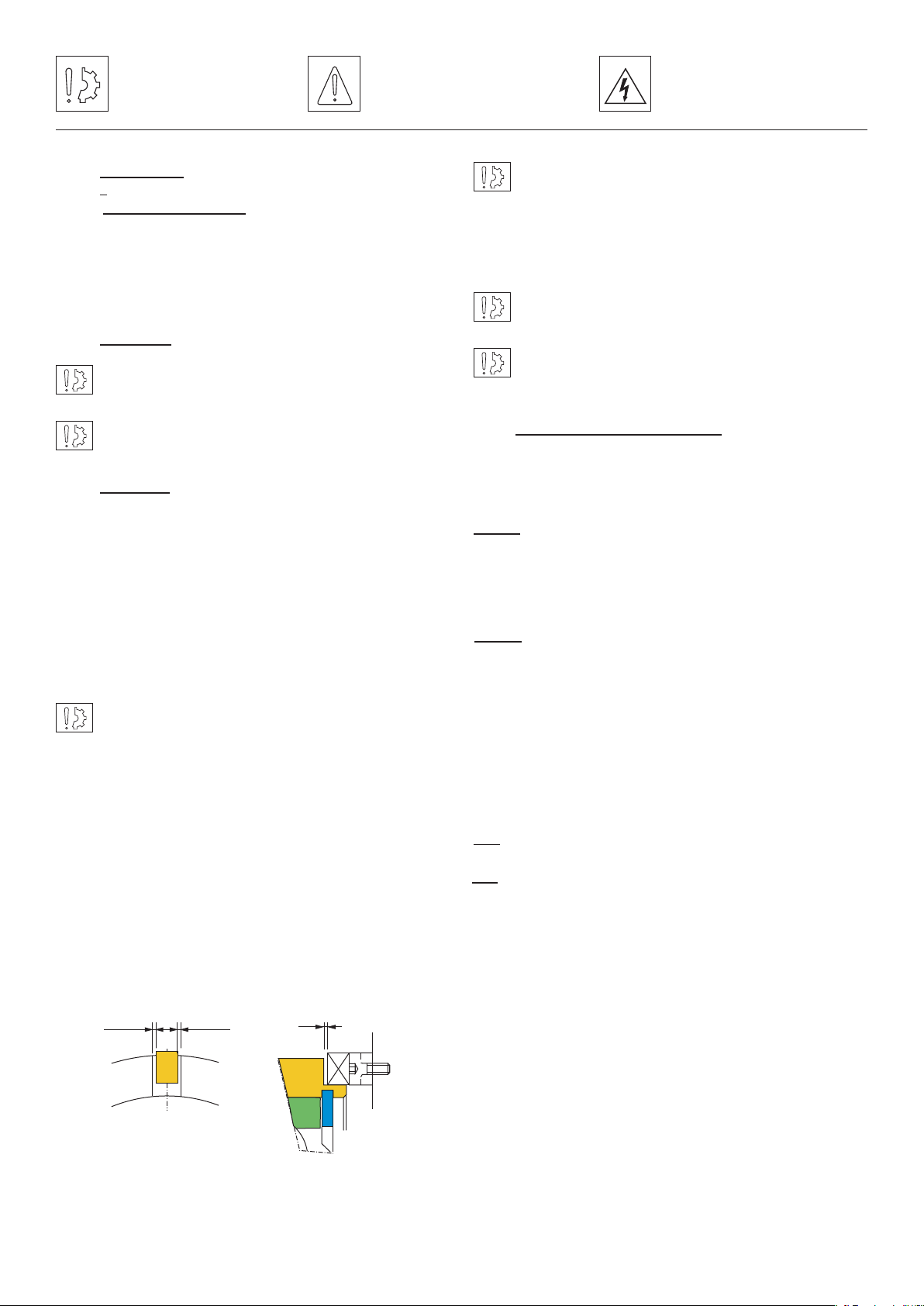
Important: Do not forget to stop the inductor
(101) rotating by means of a fixed part shaped in
the slot.
Check the play between the inductor and this part (see
fig. 1): 0,5 minimum in rotation - 1 mm at base of slot.
The part should not cause any strain on the bearings. In
case of vibrations, it is strongly recommended to insert a
damp ing elastic slot between the anti-rotation device and
the anti rotation slot and to fix the coil’s cable the nearest
of it to avoid whipping.
0,25 0,25
1
Fit the assembled moving armature (331) onto its
support housing and clamp it axially.
It is essential when assembling the 2 parts to respect
the travel P (measured in disengaged position) (see
appendix 1). To ensure axial wedging, provide for this
purpose adjustment spacers in the adaptation. Also
check, in the disengaged position, the free rotation,
without contact, of the moving armature assembly
(331).
NB: In operation, the adjusted travel at start-up can
reduce, the moving armature not returning to its initial
position. It is not necessary to make a further adjustment
unless there is rubbing, in the disengaged position,
between the friction surfaces.
Warner Electric Europe • +33 (0)2 41 21 24 24 P-2033-WE • 2/13 3
Page 4

3.3.2 Installing VAR05
• After adjusting the drive keyway, fit the assembled
inductor on the shaft, then the adjustment spacer,
followed by the assembled bearing casing, lastly
clamp the whole axially on the shaft.
Caution: The coupling flange (528) is not
factory fixed.
• After clamping the device axially on the shaft,
assemble the coupling flange (528) with the bolts
provided, tightened to torque (see Table 1) and
locked with a Loctite 243 type or equivalent product
Caution: Excess grease causes bearings to
overheat.
Reassemble the equipment following the procedure in
reverse order.
E210 and E220 VAR02 :
Bearings are greased on assembly with ELF ROLEXA
2, but they should be greased at regular intervals,
depending on use. Tables 2 and 3 below give the
intervals and average quantities of grease and a
non exhaustive list of suitable greases for normal
applications.
NB : VAR05 is supplied with a pre-set airgap, however
after fitting, check the travel (measured in disengaged
position).
• Also check in disengaged position, that
the assembled moving armature (331) rotates
without contact
• Fit the coupling hub (507) onto the 2nd shaft
• Put the spider (730) inside the coupling flange (528)
• Assemble the moving part with the receiving part
by meshing the coupling hub teeth into the hollows
of the teeth of the spider (730)
It is essential during fitting to respect dimension
E (fitting the flexible coupling) (see tabel 1 and
Appendix).
4 Maintenance
4.1 Maintenance
E210 and E220 VAR00:
Size 400 800 1600
Greasing interval
Quantity of grease (g) 12 15 30
Size 3200 6400 12800
Greasing interval
Quantity of grease (g) 45 60 85
Manufacturer Grease designation
ELF ROLEXA 2
TOTAL MULTIS 2
SHELL ALVANIA G2
SHELL MOBILUX MP2
E210 and E220 VAR02: Once maximum travel is
attained (see tabel 1) it becomes necessary to readjust
value P by using the spacers incorporated in the
assembly
3000h 3000h 3000h
2500h 1200h 1000h
Table 2
Table 3
1 year or
1 year or
Bearings are greased on assembly with ELF ROLEXA 2.
After about 5000 h running it is necessary to check the
bearings and change all grease.
Changing the grease:
Remove the circlips (947), then the inductor with its
bearings. Remove the circlips (946), then the bearings
(803). Clean the bearings, then grease them again (see
table 3 for types of grease to use). Put a quantity of
grease equivalent to one third of the volume enclosed
between the outer race and inner race.
4 Warner Electric Europe • +33 (0)2 41 21 24 24 P-2033-WE • 2/13
4.2 Spare Parts
Friction parts wear according to the amount of clutch
work which, after a particular running time, requires the
simul taneous replacement of the rotors (203) or (204)
and the moving armature assembly (331).
Page 5
5 Electrical connection
E210 and E220 clutches have to be supplied with direct
current and are factory fitted with 500 mm long wires.
The polarity does not affect operation.
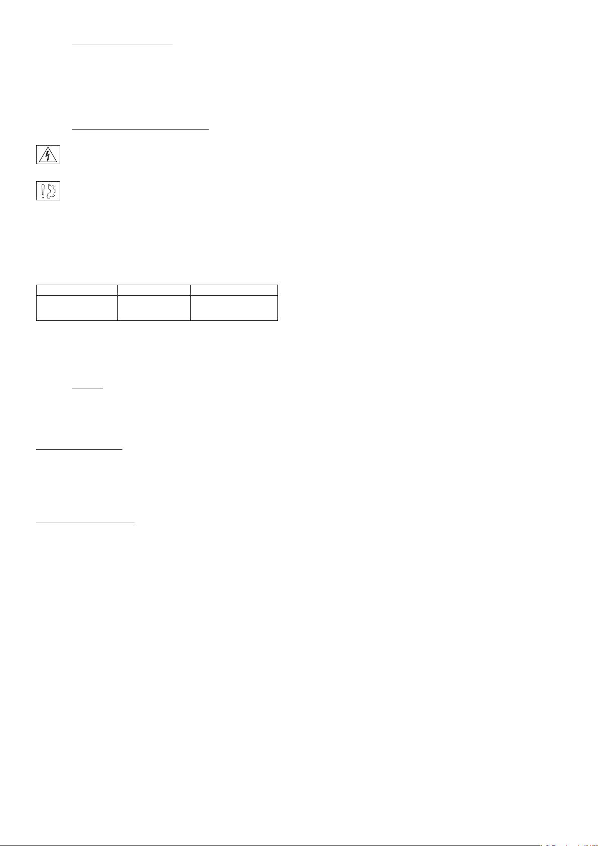
5.1 Important recommendations
All works on the electrical connections have to
be made with power off.
Ensure compliance with the nominal supply
vol tage (inadequate supply causes a reduction
in the starting distance and transmissible
torque).
The connecting wires should be of sufficient diameter
to prevent voltage drops between the source and
equipment supplied.
I (A) / L (m) 0 to 10 m from 10 to 20 m
0 to 3 (A) 1,5 mm2 1,5 mm
3 to 6 (A) 1,5 mm2 2,5 mm
2
2
Tolerance in the supply voltage to the clutch terminals
+5% / -10% (NF C 79-300).
5.2 Supply
For controlling these clutches, we advise the use of
Warner Electric’ supply units.
Sizes 400 to 1600:
CBC 400-24, CBC 450-24
CBC 500-24, CBC 550-24
CBC 140-5
Sizes 3200 to 12800:
CBC 140-5
Warner Electric supply units provide protection for
coils and circuits. Where a clutch is used without our
supply units, with switching on the DC, it is essential
for the coil to be protected against surges by a varistor
fitted in parallel.
Warner Electric Europe • +33 (0)2 41 21 24 24 P-2033-WE • 2/13 5
Page 6

6 Appendix
VAR 00 VAR 02
617 617
533
513
947
803
946
101
204 331
E210
P
E220
331
533
513
947
803
946
101
or
203
204
P
331
Nr Description
101 Magnet
203 4 poles rotor
204 4 poles rotor + friction material
331 Armature plate assy
507 Coupling hub
513 Sleeve
528 Coupling flange
533 Case
617 Connector kit (Option)
730 Spider
801 Ball bearings
803 Centering ball bearing
946 Inside circlips
947 Outside circlips
ERD VAR05
E220 VAR 00
ou
E220 VAR 02
801 528
730
617
507
E
6 Warner Electric Europe • +33 (0)2 41 21 24 24 P-2033-WE • 2/13
Page 7

Warranty
Warner Electric LLC warrants that it will repair or replace (whichever it deems advisable) any product manufactured and
sold by it which proves to be defective in material or workmanship within a period of one (1) year from the date of original
purchase for consumer, commercial or industrial use.
This warranty extends only to the original purchaser and is not transferable or assignable without Warner Electric LLC’s
prior consent.
Warranty service can be obtained in the U.S.A. by returning any defective product, transportation charges prepaid, to
the appropriate Warner Electric LLC factory. Additional warranty information may be obtained by writing the Customer
Satisfaction Department, Warner Electric LLC, 449 Gardner Street, South Beloit, Illinois 61080, or by calling 815-389-
3771.
A purchase receipt or other proof of original purchase will be required before warranty service is rendered. If found
defective under the terms of this warranty, repair or replacement will be made, without charge, together with a refund for
transportation costs. If found not to be defective, you will be notified and, with your consent, the item will be repaired or
replaced and returned to you at your expense.
This warranty covers normal use and does not cover damage or defect which results from alteration, accident, neglect, or
improper installation, operation, or maintenance.
Some states do not allow limitation on how long an implied warranty lasts, so the above limitation may not apply to you.
Warner Electric LLC’s obligation under this warranty is limited to the repair or replacement of the defective product and
in no event shall Warner Electric LLC be liable for consequential, indirect, or incidental damages of any kind incurred by
reason of the manufacture, sale or use of any defective product. Warner Electric LLC neither assumes nor authorizes any
other person to give any other warranty or to assume any other obligation or liability on its behalf.
WITH RESPECT TO CONSUMER USE OF THE PRODUCT, ANY IMPLIED WARRANTIES WHICH THE CONSUMER MAY
HAVE ARE LIMITED IN DURATION TO ONE YEAR FROM THE DATE OF ORIGINAL CONSUMER PURCHASE. WITH
RESPECT TO COMMERCIAL AND INDUSTRIAL USES OF THE PRODUCT, THE FOREGOING WARRANTY IS IN LIEU
OF AND EXCLUDES ALL OTHER WARRANTIES, WHETHER EXPRESSED OR IMPLIED BY OPERATION OF LAW OR
OTHERWISE, INCLUDING, BUT NOT LIMITED TO, ANY IMPLIED WARRANTIES OF MERCHANTABILITY OR FITNESS.
Some states do not allow the exclusion or limitation of incidental or consequential damages, so the above limitation or
exclusion may not apply to you. This warranty gives you specific legal rights and you may also have other rights which
vary from state to state.
Changes in Dimensions and Specications
All dimensions and specifications shown in Warner Electric catalogs are subject to change without notice. Weights do not
include weight of boxing for shipment. Certified prints will be furnished without charge on request to Warner Electric.
Warner Electric Europe
7 rue Champfleur, B.P. 20095, St Barthelemy d’Anjou - France
+33 (0)2 41 21 24 24 • Fax: +33 (0)2 41 21 24 70
www.warnerelectric.com
P-2033-WE • 2/13
Warner Electric Europe • +33 (0)2 41 21 24 24 P-2033-WE • 2/13 7
Printed in USA
 Loading...