

Page 1
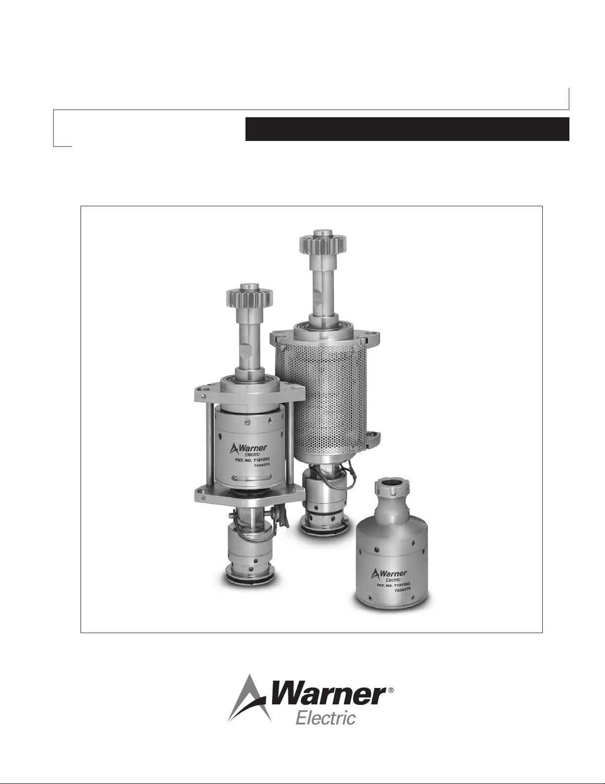
P-2021
Dairy Cap Chuck
Service & Installation Instructions
An Altra Industrial Motion Company
Page 2
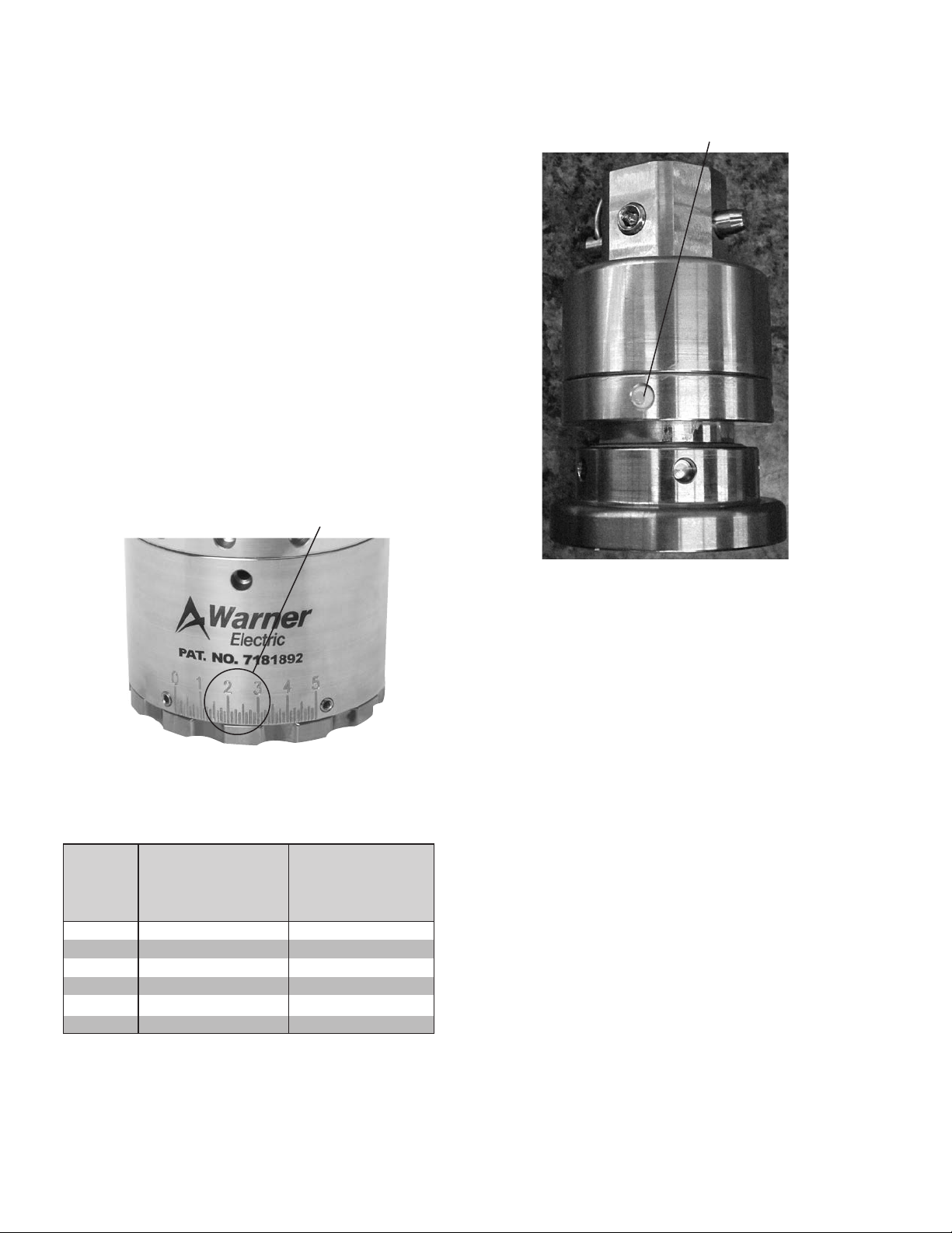
Setting Application Torque
1. Determine initial clutch setting from torque chart
below.
2. Loosen the torque adjustment screws. Rotate the
adjustment ring using the face spanner wrench to
the desired setting and then retighten the torque
adjustment screws. Do not use the set screw in
the slot on the backside of the housing for torque
adjustment. Tighten set screws to 8-10 lb-in.
Over tightening is not necessary and will strip the
screws or possibly damage the housing body.
3. For optimum results, check setting with a torque
wrench and FIX-0115* or FIX-0138.
*For use with DBJ closure
Application
Torque Setting
Recommended Maintenance
For CHF38-035 Chuck
Grease Port
Figure 1
Application Torque Setting Charts
Clutch
Setting
0.00 3.00 11.00
1.00 4.00 12.00
2.00 8.00 17.00
3.00 13.00 22.00
4.00 16.00 26.00
5.00 18.00 28.00
Application Torque
Standard Torque
Units (lb-in)
Application Torque
High Torque Units
(lb-in)
Figure 2
Disassemble, clean, and replace all wearing
parts in the headset every 7000 hours of
machine run time.
- See rebuild instructions for detailed information on
disassembly and assembly of Warner headsets.
- Dependent upon machine speed and washdown
procedure, some environments may require more
frequent rebuilds.
- CHF38-035 chucks cannot be submerged in
water. Proper cleaning procedures for the chucks
include wipe down operations or foaming. If
necessary chucks can be taken apart, cleaned
and rebuilt.
- Chucks can be greased if needed using lubrication
hole in chuck and needle fitting on grease gun.
Do not over grease as this will cause the chucks to
stick.
Note: CHF38-037 and later model chucks may be
submerged in water or COP/CIP cleaners. No
re-greasing is required.
2 Warner Electric • 800-825-9050 P-2021
Page 3
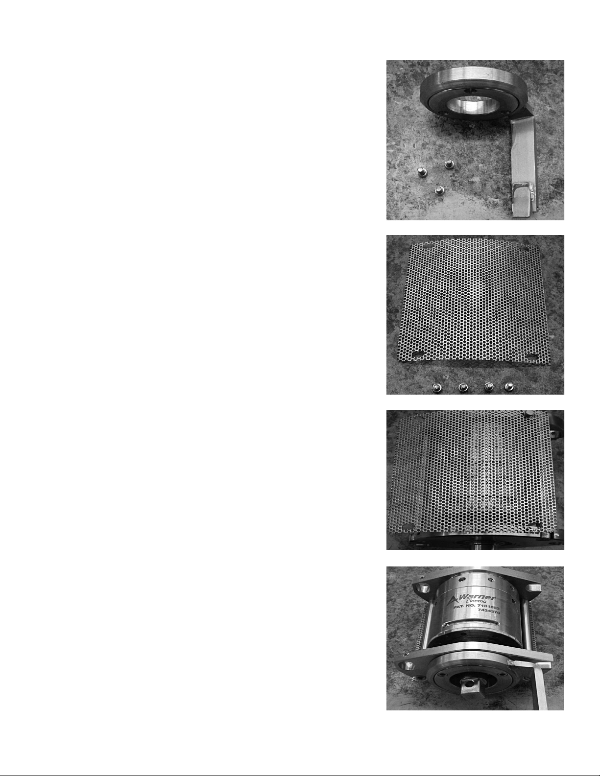
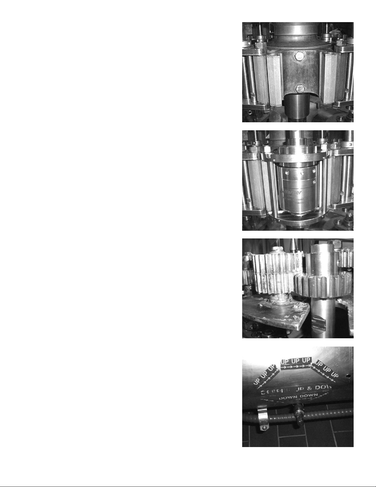
Installing Clutch
Remove handle. Set aside finger, three socket
head cap screws and lock washers. See figure 3.
Remove screen. Set aside screen, 4 screws, and
4 lock washers. See figure 4.
Figure 3
Install screen, 4 lock washers, and 4 screws onto
new unit. It may be necessary to widen original
holes on screen. See figure 5.
Install finger onto new unit. See figure 6.
*Depending on previous equipment a longer
nger may be necessary.
Figure 4
Figure 5
Figure 6
Warner Electric • 800-825-9050 P-2021 3
Page 4
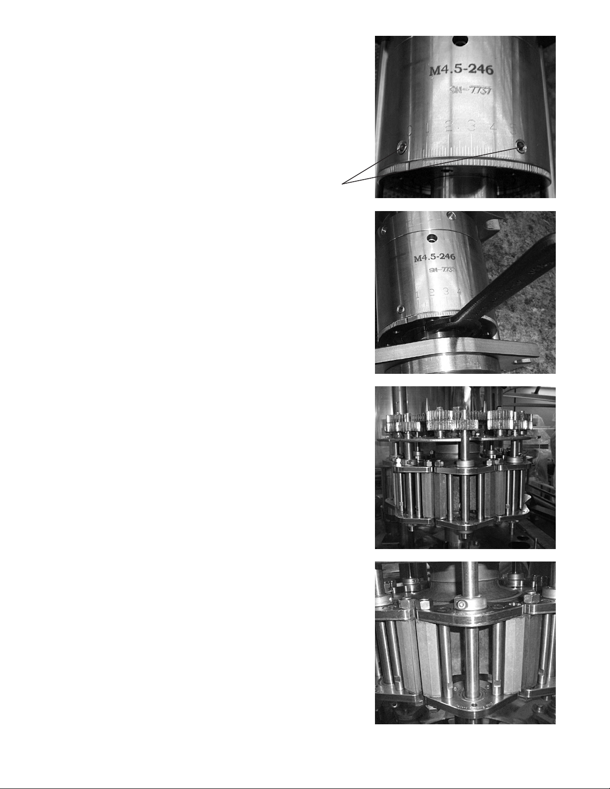
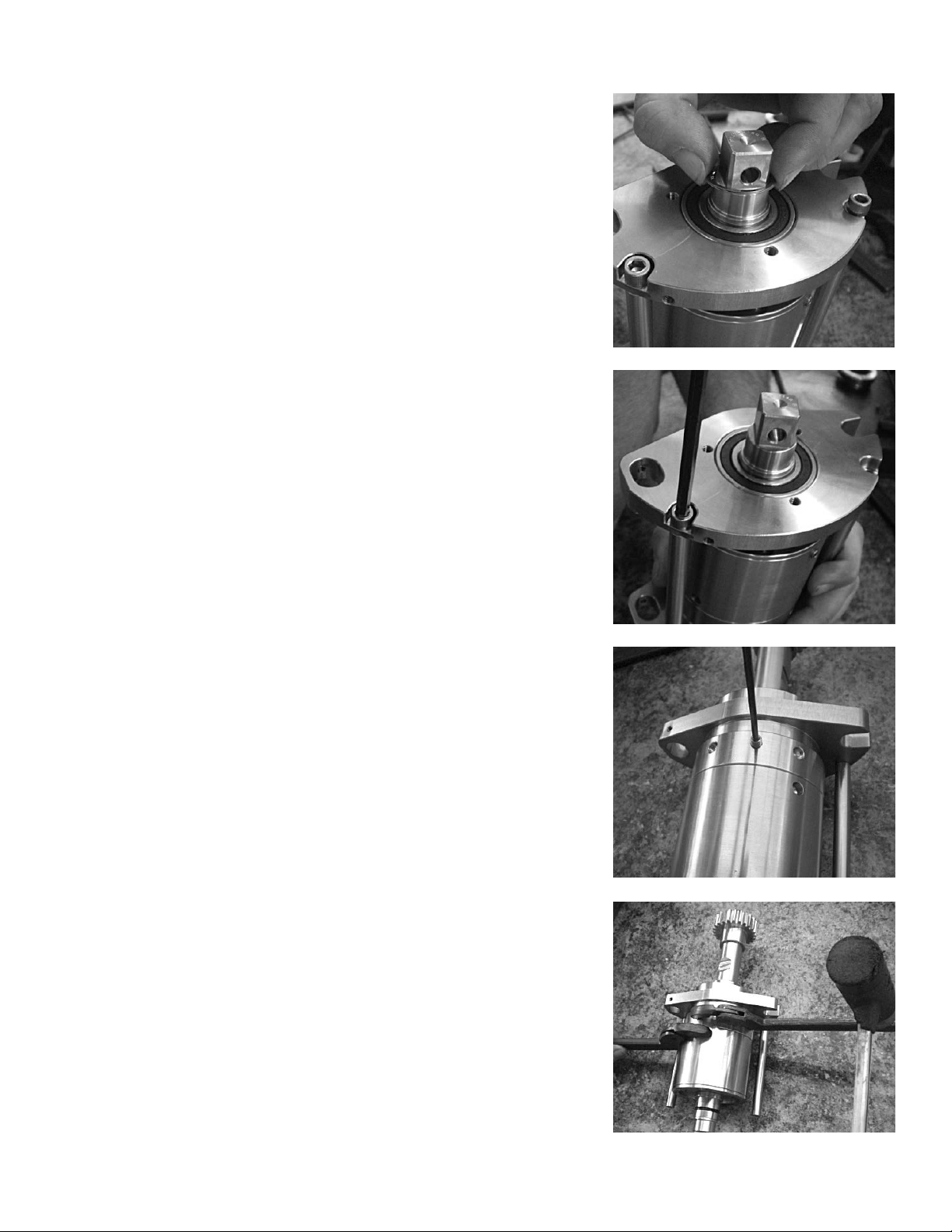
To set torque loosen the two set screws using
3mm Hex wench. Tighten set screws to 8-10 lbin. Over tightening is not necessary and will strip
the screws or possibly damage the housing body.
See figure 7.
Align visual marking with desired setting. Using a
face spanner wrench (YTL2-0002). Then tighten
down set screws. See figure 8.
Set Screws
Figure 7
Figure 8
Remove turret cover from top of machine.
See figure 9.
Figure 9
Remove the two bolts that hold the unit to the
machine. Set the bolts aside for later use. See
figure 10.
Figure 10
4 Warner Electric • 800-825-9050 P-2021
Page 5
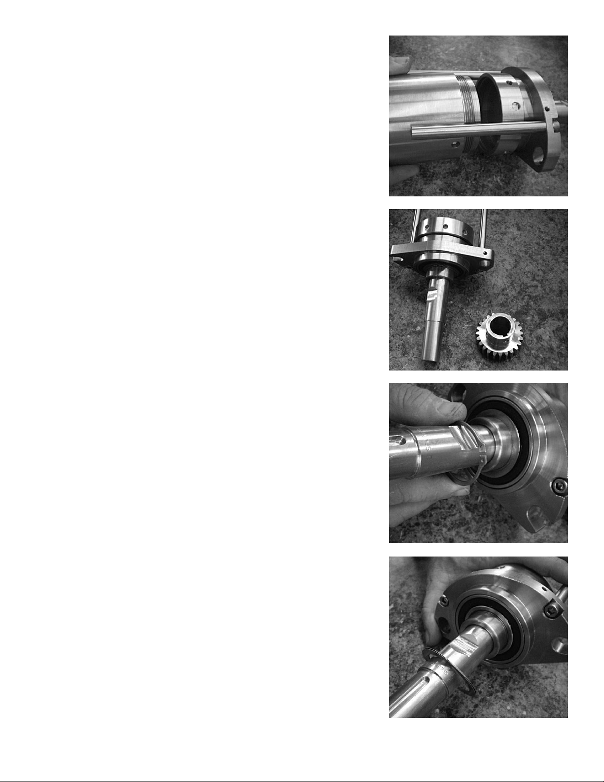
Remove old unit from the machine. See figure 11.
Install new unit onto the machine. Use original two
bolts to secure unit from Figure 15. See figure 12.
Figure 11
Adjust gear position where necessary using 3mm
Hex wrench. Apply proper food grade lubricant to
gears. See figure 13.
Clutch installation is now complete. Install
remainder of clutches in the same manner. Adjust
clutch torque and machine turret height as needed.
See figure 14.
Figure 12
Figure 13
Figure 14
Warner Electric • 800-825-9050 P-2021 5
Page 6
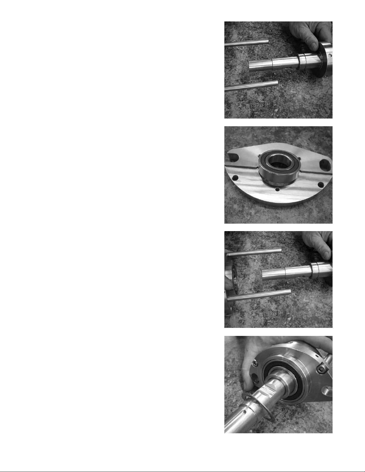
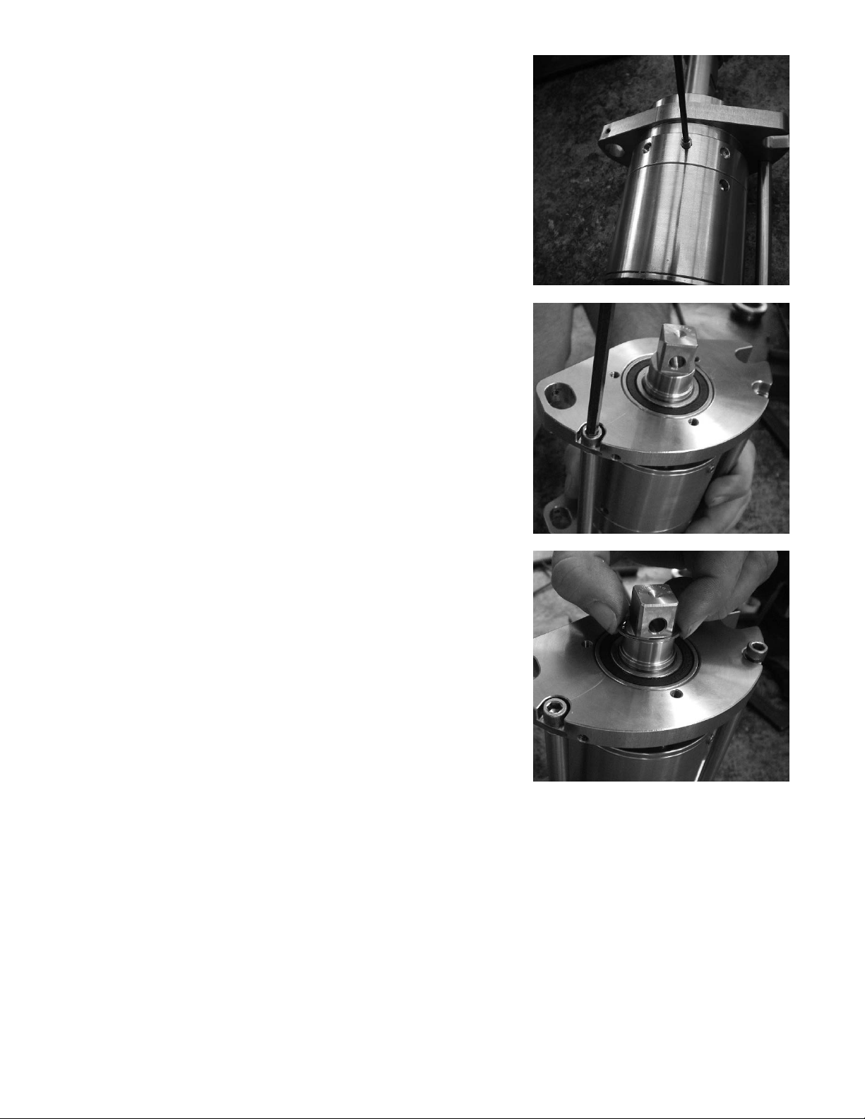
Outer Bearing Rebuild
Remove snap ring from bottom plate. See figure 15.
Remove screws from bottom plate using 3/16” (3mm)
hex wrench. Remove bottom plate from unit. See
figure 16.
Figure 15
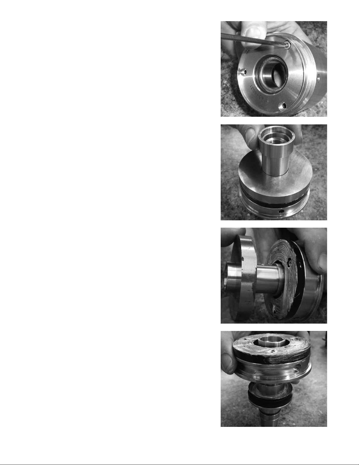
Remove set screw on the backside of housing using
3mm hex wrench. See figure 17.
Using spanner wrenches (YTL3-0008) and rubber
mallet separate clutch from top adapter. See figure 18.
Figure 16
Figure 17
Figure 18
6 Warner Electric • 800-825-9050 P-2021
Page 7
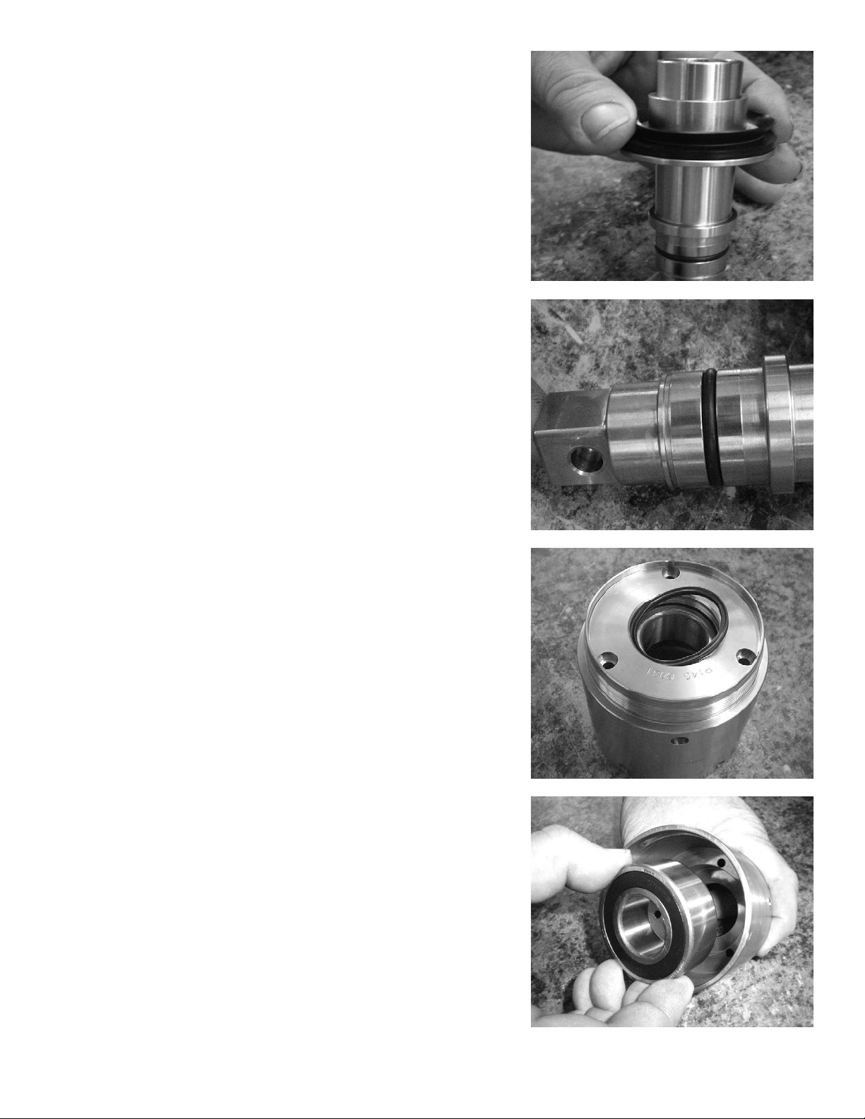
Remove clutch from top adapter. See figure 19.
Remove gear from shaft using 3mm Hex wrench.
See figure 20.
Figure 19
Remove retaining ring from shaft. See figure 21.
Remove shims from shaft. See figure 22.
Figure 20
Figure 21
Figure 22
Warner Electric • 800-825-9050 P-2021 7
Page 8
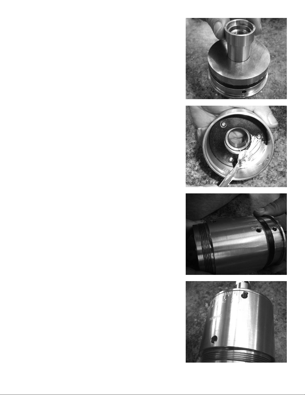
Remove shaft from top plate. See figure 23.
Replace the two bearings in the top plate.
Replace bearing in bottom plate. See figure 24.
Figure 23
Install shaft with adapter onto top plate. See figure
25.
Install shims onto shaft. See figure 26.
Figure 24
Figure 25
Figure 26
8 Warner Electric • 800-825-9050 P-2021
Page 9

Install retaining ring onto shaft. See figure 27.
Install gear onto top of shaft using 3mm Hex
wrench. See figure 28.
Figure 27
Install clutch onto adapter. See figure 29.
Using spanner wrenches (YTL3-0008) and rubber
mallet tighten down clutch onto adapter. See figure
30.
Figure 28
Figure 29
Figure 30
Warner Electric • 800-825-9050 P-2021 9
Page 10
Install set screw on back side of housing using
3mm hex wrench. Tighten set screws to 8-10 lbin. Over tightening is not necessary and will strip
the screws or possibly damage the housing body.
See figure 31.
Install bottom plate over shaft of clutch. Install
screws using 3/16” hex wrench onto bolts to hold
plate in place. See figure 32.
Figure 31
Install snap ring over shaft of clutch. See figure 33.
Figure 32
Figure 33
10 Warner Electric • 800-825-9050 P-2021
Page 11

Clutch Rebuild Procedure
Place unit into vice. Using FIX-0019 and 1 1/8”
or 28mm” socket wrench remove nut from top of
housing. See figure 34.
Remove the two set screws from housing of unit
using a 3mm hex wrench. See figure 35.
Figure 34
Move adjustable end plate until spring and pin are
visible. Remove pin and spring from housing. See
figure 36.
Pull magnet stack away from housing. Set magnet
stack aside. See figure 37.
Figure 35
Figure 36
Figure 37
Warner Electric • 800-825-9050 P-2021 11
Page 12
Remove three cap screws from top of housing
using 3mm hex wrench. Remove black driver
magnet from housing. See figure 38.
Remove spacer from magnet stack. See figure 39.
Figure 38
Figure 39
Remove hysteresis magnet from magnet stack.
See figure 40.
Remove adjustable end plate with black driver
magnet from shaft. See figure 41.
Figure 40
Figure 41
12 Warner Electric • 800-825-9050 P-2021
Page 13
Remove spacer and grease seal. See figure 42.
Remove O-ring from shaft. See figure 43.
Figure 42
Figure 43
Remove seal from top of housing. See figure 44.
Using an arbor press remove bearing from inside of
housing. See figure 45.
Figure 44
Figure 45
Warner Electric • 800-825-9050 P-2021 13
Page 14

You will now have all of the pieces shown in the
picture to the right. Clean all pieces and replace
parts as needed. Use an alcohol based cleaning
solvent to clean the black driver magnets. Do
not use anything abrasive when wiping the black
driver magnets. Use a Scotch Brite deburr wheel
to polish the hysteresis magnet. See figure 46.
Turn housing over. Press new bearing in housing
using FIX-0002 and an arbor press. See figure 47.
Figure 46
Put in new seal. See figure 48.
Install end cap with black driver magnet into
housing. Be sure to line up holes for set screws.
See figure 49.
Figure 47
Figure 48
Figure 49
14 Warner Electric • 800-825-9050 P-2021
Page 15

Reinstall three cap screws on top of housing using
3mm hex wrench. See figure 50.
Place grease seal over spacer. See figure 51.
Figure 50
Figure 51
Install o-ring into grove of shaft. See figure 52.
Slide spacer with grease seal onto shaft. See figure
53.
Figure 52
Figure 53
Warner Electric • 800-825-9050 P-2021 15
Page 16

Once the spacer is placed on the shaft. Apply
thin layer of grease to the seal. See figure 54.
Apply thin layer of grease to black driver magnet
that is attached to the adjustable end plate. See
figure 55.
Figure 54
Slide adjustable end plate and magnet onto shaft.
See figure 56.
Slide hysteresis magnet onto shaft so that it rests
on the black driver magnet. See figure 57.
Figure 55
Figure 56
Figure 57
16 Warner Electric • 800-825-9050 P-2021
Page 17
Install spacer onto shaft. See figure 58.
Apply thin layer of grease to black driver magnet
inside housing. See figure 59.
Figure 58
Place magnet stack inside of housing. Line up the
hole on the adjustable end plate with one of the
set screw holes on the housing. Be careful as the
magnets will attract together and snap into place.
See figure 60.
Place small spring inside of the aligned holes. Then
place pin, flat side up, into the hole. See figure 61.
Figure 59
Figure 60
Figure 61
Warner Electric • 800-825-9050 P-2021 17
Page 18

Press down on pin with allen wrench and place
spanner wrench (YTL2-0002) onto adjustable
end plate. Turn the allen wrench and the spanner
wrench at the same time to lock pin into place.
See figure 62.
Turn adjustable end plate until witness mark falls
between the O and 5 torque markings. See figure
63.
Figure 62
Install the two set screws onto front of housing
using 3mm hex wrench. Do not tighten down yet.
See figure 64.
Place unit back into the vice. Apply Blue loctite to
the thread of the nut. Using FIX-0019 and 1 1/8”
or 28mm socket wrench reinstall the nut. Torque
nut down to 45 ft. lb. See figure 65.
Figure 63
Figure 64
Figure 65
18 Warner Electric • 800-825-9050 P-2021
Page 19

Using spanner wrench (YTL2-0002) adjust to
desired torque setting. See figure 66.
Tighten down set screws using 3mm hex wrench.
Tighten set screws to 8-10 lb-in. Over tightening is
not necessary and will strip the screws or possibly
damage the housing body. Reinstall unit. See figure
67.
Figure 66
Figure 67
Warner Electric • 800-825-9050 P-2021 19
Page 20

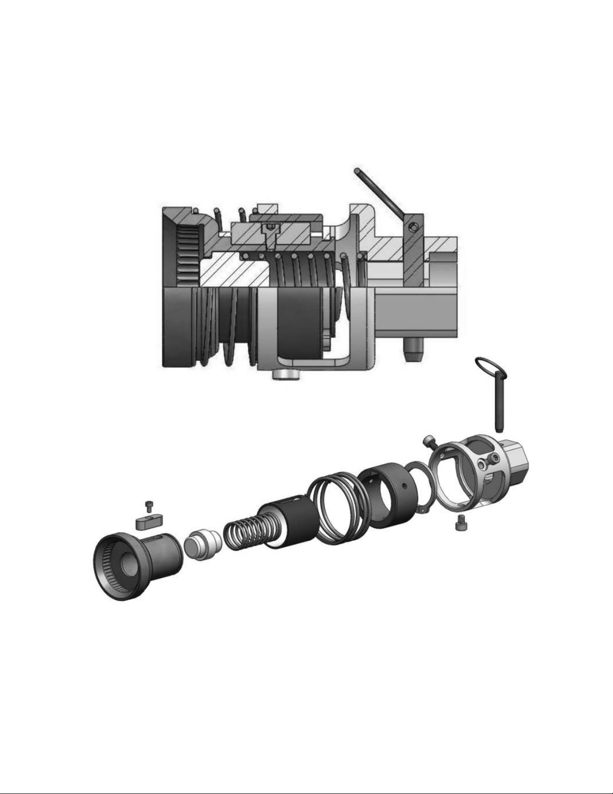
CHF38-035
Exploded View for Chuck Rebuild
Use Loctite on this
Connection
Grease Here
(4 Hole Locations)
20 Warner Electric • 800-825-9050 P-2021
Page 21
CHF38-037 & Later Models
Exploded View for Chuck Rebuild
(non-grease chuck)
Warner Electric • 800-825-9050 P-2021 21
Page 22

On-site Service Support
Warner Electric Capping Headsets
On-site service support is available for installation of new Warner headsets, rebuild support of existing Warner
headsets, training, etc. Our factory-trained and certified service department with over 50 years combined
experience can help prevent costly delays and down time of your capping operation.
Precision Tork is the ONLY Service Group that is factory
authorized to work on the Warner Electric headsets.
Services Provided:
• Installation of new equipment
• Machine audits and troubleshooting
• Service and repair of filling and capping equipment
• Consulting: New Installations-existing issues for filling and capping
• Develop new design for efficient production
• Assist with planning of preventative maintenance programs
• Operator and mechanical training
• Highly qualified trained field engineers ready to work on the following bottling equipment:
• Alcoa • Zalkin • Fowler • AROL
Precision Tork Service Benets:
• We manufacture the headsets!
• Most up-to-date designs available only through Precision Tork.
• Our service technicians are trained to rebuild your headsets to their existing revision level
OR upgrade them to the latest technology.
• Component parts and rebuild kits on hand so you do not incur downtime.
• Coming soon…secure website for headset information and parts ordering with a credit card.
To schedule a certied Warner Service Technician
contact Melissa Bottke at 1-888-350-1891
22 Warner Electric • 800-825-9050 P-2021
Page 23

Trouble Shooting
• Proper Operation: Before cap comes out of chuck the chuck should reach a stall point. At that point cap
will be completely tightened on bottle. It is important to have proper turret height and clutch torque
adjustment for this to occur.
• Loose Caps
• Torque setting on clutch to low; increase torque setting on clutch
• Turret position set to high while cap is being screwed onto bottle
• Cap will be pulled from chuck before properly tightened. To correct, lower turret of machine.
• Bottle Damage
• Can result if turret is set to low.
• Chuck will cause cap to be crushed onto bottle.
• To correct raise turret of machine.
• Sticky Chuck Float
• For proper operation, chuck must float up and down approximately 0.2 inches.
• If grease is washed out of chuck and chuck becomes dry, re-greasing chuck will become necessary.
• Chuck should move easily in and out without hang ups.
Information for Ordering Spare Parts
It is important to stock spare parts on hand to avoid unnecessary downtime. Warner recommends that you
stock at least two spare headsets per machine and a few bearing and magnet rebuild kits so that you have
the necessary parts on hand if you need them.
How to order spare parts – required information:
1. Purchase Order Number.
2. Warner headset model number/part number OR serial number
(only on models manufactured July 2007 and later).
3. Warner Component or Kit Part Number.
4. Preferred distributor to order from.
All orders will be routed through local distribution. Pricing and lead-time can be quoted by calling the
Manufacturing Facility at (888) 350-1891.
Warner Electric • 800-825-9050 P-2021 23
Page 24

Warranty
Warner Electric LLC warrants that it will repair or replace (whichever it deems advisable) any product
manufactured and sold by it which proves to be defective in material or workmanship within a period of one (1)
year from the date of original purchase for consumer, commercial or industrial use.
This warranty extends only to the original purchaser and is not transferable or assignable without Warner Electric
LLC’s prior consent.
Warranty service can be obtained in the U.S.A. by returning any defective product, transportation charges
prepaid, to the appropriate Warner Electric LLC factory. Additional warranty information may be obtained by
writing the Customer Satisfaction Department, Warner Electric LLC, 449 Gardner Street, South Beloit, Illinois
61080, or by calling 815-389-3771.
A purchase receipt or other proof of original purchase will be required before warranty service is rendered. If
found defective under the terms of this warranty, repair or replacement will be made, without charge, together
with a refund for transportation costs. If found not to be defective, you will be notified and, with your consent, the
item will be repaired or replaced and returned to you at your expense.
This warranty covers normal use and does not cover damage or defect which results from alteration, accident,
neglect, or improper installation, operation, or maintenance.
Some states do not allow limitation on how long an implied warranty lasts, so the above limitation may not apply
to you.
Warner Electric LLC’s obligation under this warranty is limited to the repair or replacement of the defective
product and in no event shall Warner Electric LLC be liable for consequential, indirect, or incidental damages of
any kind incurred by reason of the manufacture, sale or use of any defective product. Warner Electric LLC neither
assumes nor authorizes any other person to give any other warranty or to assume any other obligation or liability
on its behalf.
WITH RESPECT TO CONSUMER USE OF THE PRODUCT, ANY IMPLIED WARRANTIES WHICH THE
CONSUMER MAY HAVE ARE LIMITED IN DURATION TO ONE YEAR FROM THE DATE OF ORIGINAL
CONSUMER PURCHASE. WITH RESPECT TO COMMERCIAL AND INDUSTRIAL USES OF THE PRODUCT,
THE FOREGOING WARRANTY IS IN LIEU OF AND EXCLUDES ALL OTHER WARRANTIES, WHETHER
EXPRESSED OR IMPLIED BY OPERATION OF LAW OR OTHERWISE, INCLUDING, BUT NOT LIMITED TO,
ANY IMPLIED WARRANTIES OF MERCHANTABILITY OR FITNESS.
Some states do not allow the exclusion or limitation of incidental or consequential damages, so the above
limitation or exclusion may not apply to you. This warranty gives you specific legal rights and you may also have
other rights which vary from state to state.
Changes in Dimensions and Specications
All dimensions and specifications shown in Warner Electric catalogs are subject to change without notice.
Weights do not include weight of boxing for shipment. Certified prints will be furnished without charge on request
to Warner Electric.
www.warnerelectric.com
31 Industrial Park Road
New Hartford, CT 06057
800-389-3771
Fax: 815-389-2582
P-2021-WE 3/14 Printed in USA
An Altra Industrial Motion Company
www.altramotion.com
 Loading...