

Page 1
Compressor Clutch
Replacement Procedure
P-1401
819-0316
Installation Instructions
Page 2
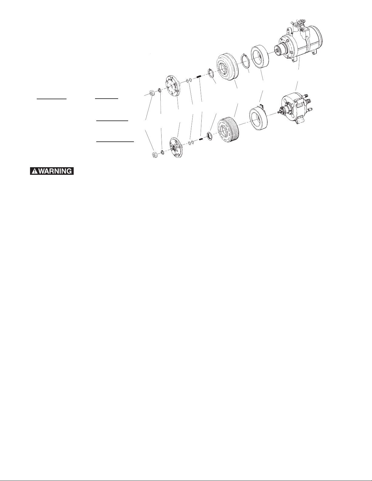
Warner Replacement Clutches
11
Shaft Nut
10
Lock
Washer
8
Shims
7
Key
6
Rotor/Pulley
Retainer nut
4
Rotor/Pulley
Assembly
2
Field Coil
1
Compressor
9
Hub/Armature
Assembly
5
Rotor/Pulley
Snap Ring
3
Field Coil
Snap Ring
HR980
FS6, C171, A590,
6E171, 10P15,
6P148, 6717
for the following compressors:
Denso
6E171
10P15
6P148
6C17
Ford
FS-6
Chrysler
C-171
Tecumseh
HR980
Failure to follow these
instructions may result in product damage,
equipment damage, and serious or fatal
injury to personnel.
Note: During compressor clutch removal DO
NOT pound on the clutch or compressor as
damage will result.
Step 1: Diagnose Clutch Failure
Most compressor clutch failures are a direct
result of an A/C system problem or failure.
Before installing a new clutch, determine what
caused the old clutch to fail and fix the system
problem. By simply replacing the clutch without
fixing the cause of the clutch failure, the new
clutch may fail in the same manner as the old
clutch. Please refer to the Warner Electric "Air
Conditioning Clutch Trouble Shooting Guide"
and the appropriate manufacturer's A/C
Service Manuals.
Warner Electric • 800-825-9050 P-1401 • 819-0316
2
Step 2: Removal of Hub/Armature Assembly
(9)
Special tools must be used to avoid damaging
the compressor.
A. Remove shaft nut (11) with a 13mm socket
wrench and spanner wrench.
B. Remove lock washer (10).
C. Remove hub/armature (9) with a hub/armature
removal tool (reference Chrysler Tool # C-4561
or equivalent).
D. Remove shims (8) from the hub/armature and
shaft.
Step 3A: Removal of Rotor/Pulley Assembly
(4) (All compressors except HR980)
A. Remove rotor/pulley snap ring (5).
B. Slide rotor/pulley assembly (4) off the
compressor (1) nose. If rotor/pulley assembly
is hot and will not slide, DO NOT FORCE! Allow
the clutch to cool and then proceed.
C. Proceed to Step 4.
Page 3
Step 3B: Removal of Rotor/Pulley
Mounting
Surfaces
Assembly (4) and Field Coil Assembly (2)
(HR980 Compressor only)
A. Disconnect the electrical connection on the
field coil (2).
B. Unscrew the rotor/pulley retainer nut (6) with a
spanner wrench.
C. Slide the rotor/pulley assembly (4) off the
compressor (1) nose. If rotor/pulley assembly
is hot and will not slide, DO NOT FORCE!
Allow the clutch to cool and then proceed.
D. Remove field coil assembly (2).
Step 4: Removal of Field Coil Assembly (2)
(All compressors except HR980)
A. Separate electrical connection and, if
applicable, remove clutch wire retaining clip
from the compressor.
Installing Clutch on Compressor
Replace the complete clutch to ensure required
performance is achieved and warranty
requirements are met.
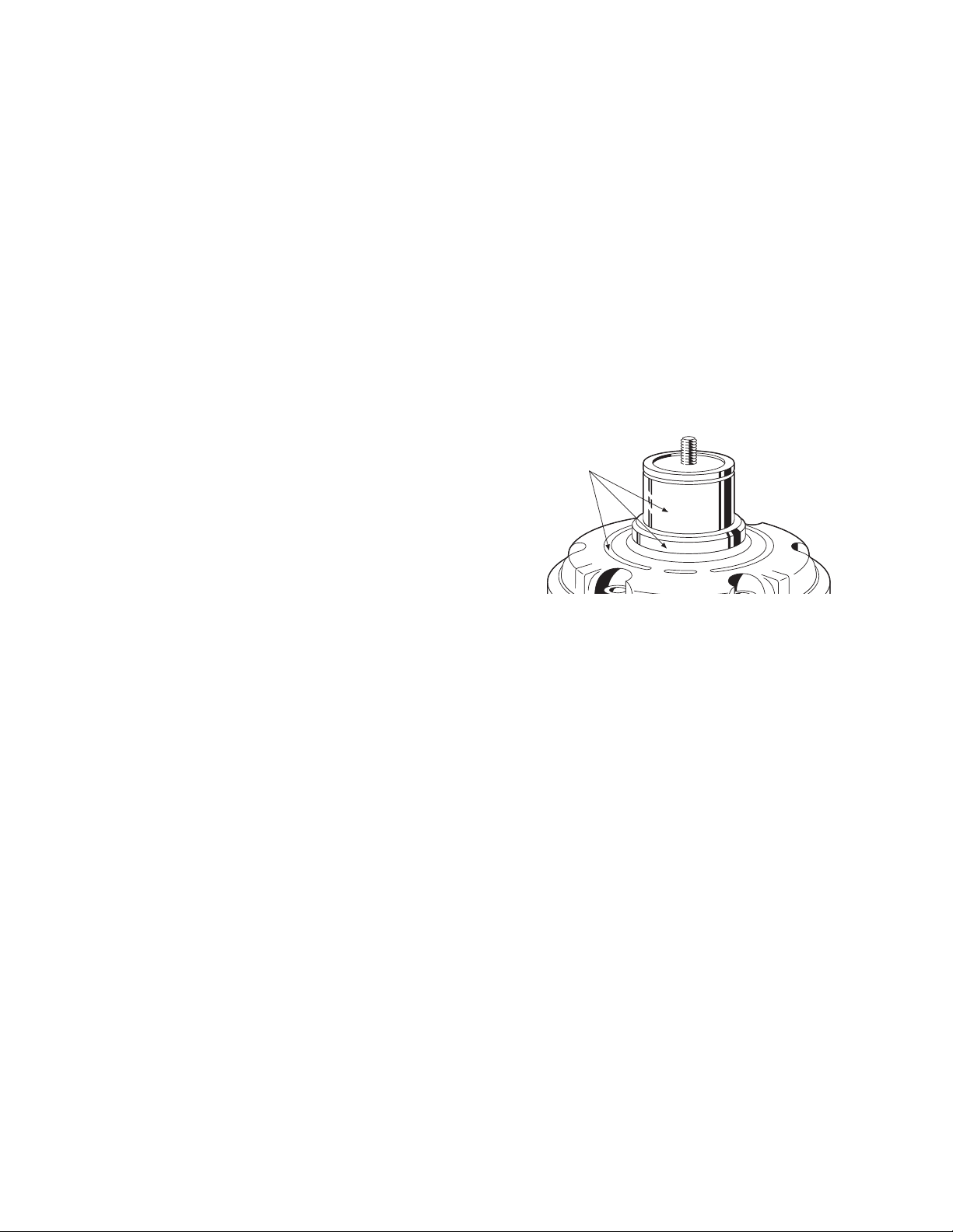
Step 1: Preparation of Compressor
A. Clean compressor nose of all dirt, grease
or debris. Check for evidence of oil leakage
from the front seal and through bolts of the
compressor. Repair or replace compressor
as appropriate.
B. Check mounting surfaces for nicks, burrs and
scratches (See Figure 1). Smooth with a file
or emery cloth, if necessary.
B. Remove field coil snap ring (3) retaining the
field coil.
C. Remove the ground screw on the compressor,
if used.
D. Slide the field coil (2) off the compressor
housing.
Figure 1
C. Make an electrical system check with all
electrical accessories turned on to ensure
that the voltage available to the clutch is
10.8 volts minimum.
Warner Electric • 800-825-9050 P-1401 • 819-0316
3
Page 4

Step 2A: Installing the Field Coil (2)
Rotor/Pulley
Assembly
Hub/Armature
Assembly
Field Coil
Assembly
Field Coil Assembly
Snap Ring
Compressor
Rotor/Pulley Assembly
Snap Ring
Fully seated
snap ring
Bevel
Compressor
Install with beveled face away from compressor
Snap Rings
Compressor
Correct
Incorrect
Clutch
Field
Coil
Assembly
Compressor
Rotate
Remove
Slack
Taut
Wire
PRE-1981
0.058 to 0.065
Inches Thick
POST-1981
0.075 to 0.081
Inches Thick
Thickness
Measurement
(All Compressors except HR980)
Note: Failure to install snap rings per these
instructions can be verified and will void the
compressor clutch warranty.
A. Align the hole in the back plate of the field
coil (2) with the anti-rotation pin in the
compressor end housing. Place the field
coil into position. Make sure that the lead
wires are routed directly to the retaining
clip on top of the compressor.
B. Install field coil snap ring (3).
Figure 2
Use the Correct Retaining Ring (3)
During the 1981 model year, the retaining
ring used to hold the Chrysler C171 field coil
assembly (2) in place was made thicker. Check
the thickness of the old ring which was removed
and verify that the new ring is the same
thickness (*except 6C17 Compressor). The field
coil assembly must be tight on the compressor.
*For a 6C17 Compressor, Install the field coil
assembly (2) with the retaining ring (3) provided
with the new Warner clutch. Discard the old
retaining ring.
Location of Clutch Snap Rings
Figure 3
Snap Ring
Correct and Incorrect Installation
Bevel
Note: When attaching the clutch ground wire to
the compressor, rotate the ring terminal
COUNTERCLOCKWISE to remove slack in
the wire. Failing to remove slack may result
in the pulley rubbing on the ground wire on
some models.
Figure 4
With a snap ring pliers, spread the field coil
snap ring (3) and insert it into the groove on the
compressor nose. (See Figure 2) To assure
assembly retention, ring bevel must face away
from the compressor. (See Figures 3 and 4)
Verify that the snap ring is fully seated in the
groove around its circumference to assure
assembly retention. (See Figure 4)
Attach the ground lead, if used, to the
compressor housing and tighten the screw
to 17 lb.in. torque. (See Figure 5)
Warner Electric • 800-825-9050 P-1401 • 819-0316
4
Right Wrong
Figure 5
Page 5

Rotor/Pulley
Retaining Nut
Hub/Armature
Assembly
Rotor/Pulley
Assembly
Field Coil
Assembly
Compressor
HR980
Step 2B: Installing the Field Coil (2)
and Rotor/Pulley Assembly (4) (HR980
Compressor only)
Step 3: Installing the Rotor/Pulley
Assembly (4) (All Compressors except
HR980)
A. Align square holes in the back plate of the
coil assembly (2) with lugs on the compressor
(1) housing.
B. With the field coil (2) in position, slide the
rotor/pulley (4) onto the compressor until it
butts against the field coil (2). (See Figure 6)
If the the rotor/pulley does not slide on easily,
check the mounting surface on the
compressor nose for nicks or burrs and
remove them. If the rotor/pulley still does not
slide on easily, rock the rotor/pulley back and
forth by hand until it slides completely onto
the compressor.
C. Install the rotor/pulley retainer nut (6) with
flange notches facing AWAY from the
rotor/pulley assembly. Tighten the retainer nut
to 65 to 75 lb.ft. torque.
D. Make electrical connection.
E. Proceed to Step 4.
Do not mar the rotor/pulley
and hub/armature friction surfaces.
Prevent any oil or grease from
contaminating the friction surfaces.
A. Install the rotor/pulley assembly (4) onto the
compressor (1). If the rotor/pulley does not
slide on easily check the compressor nose for
nicks or burrs and remove. If the rotor/pulley
still does not slide on easily, rock the
rotor/pulley back and forth by hand until it
slides completely onto the compressor (1).
B. Make sure there is no interference between
the field coil (2) or lead wires and the rotating
rotor/pulley (4).
C. Install the rotor/pulley snap ring (5). With a
snap ring pliers, spread the snap ring and
insert it into the groove on the compressor
nose. (See Figure 2) To assure assembly
retention, the snap ring bevel must face away
from the compressor. (See Figures 3 and 4)
Figure 6
The snap ring pliers must not
contact the bearing seal or a seal failure may
result.
D. Verify that the snap ring (5) is fully seated
in the groove around its circumference to
assure assembly retention. (See Figure 4)
Warner Electric • 800-825-9050 P-1401 • 819-0316
5
Page 6

0.020
(0.51)
0.040
(1.02)
Rotor/Pulley to
Hub/Armature Airgap
(Measured 3 places
120° apart)
to
Step 4: Installing the Hub/Armature
Assembly (9)
A. Align the hub keyway with shaft key (7) and
slide the hub/armature (9) onto the compressor
shaft.
B. Set the rotor/pulley to hub/armature air gap at
0.020 to 0.040 inches by adding or removing
shims (8). Measure using a feeler gauge at 3
locations 120° apart. (See Figure 7)
C. Install the lockwasher (10) and shaft nut (11).
Torque to 155 lb.in. using a torque wrench and
spanner wrench.
Use a hub/armature removal
tool (reference Chrysler tool C-4561 or
equivalent) to install and remove the
hub/armature (9).
Do not use screwdrivers
between the hub/armature and rotor/pulley
to remove hub/armature as clutch will be
damaged.
Step 5: Clutch Assembly Check
A. Rotate the clutch and check for rubbing or
interference.
B. Reinstall belts per manufacturer's service
manual. Do not over tighten.
C. Recheck the airgap at 3 or 4 points and
check for clutch rubbing.
D. Important: Burnish as follows. Run the
clutch at 2500 to 3000 RPM. Cycle the clutch
ON and OFF at a rate of 10 to 15 times per
minute maximum for a total of 50 cycles
minimum. This should bring the clutch up
to operating torque capacity.
Cycle the clutch using the
controls inside the car or electrical system
damage could result.
Note: The shims (8) may compress when the
shaft nut (11) is tightened; therefore, recheck
the airgap at three locations 120° apart.
Figure 7
Warner Electric • 800-825-9050 P-1401 • 819-0316
6
Page 7

Troubleshooting Checklist
For failure diagnosis of the clutch being replaced, (the failed clutch), refer to the Warner Electric
Troubleshooting Guide (form P-1011) and the appropriate A/C manufacturer's Service Manuals.
Use the guide below to troubleshoot the new clutch.
A. Symptom: Clutch will not disengage
Possible Causes Solution
• Improper hub/armature to rotor/pulley • Reset air gap (See Figure 7)
air gap (too small)
• Current is always on • Check electrical system
• Rotor/pulley snap ring not installed • Install per instructions (See Step 2)
correctly
B. Symptom: Clutch will not engage
Possible Causes Solution
• Improper hub/armature to rotor/pulley • Reset air gap (see Figure 7)
air gap (too big)
• Field coil electrical wiring is not connected • Connect field coil wiring
• Faulty field coil • Check field coil for continuity
• Less than 10.8 volts supplied to field coil • Check electrical system
(all accessories on)
C. Symptom: Clutch is noisy
Possible Causes Solution
• Field coil or rotor pulley snap rings • Check for correct installation (See Step 2)
are not installed correctly
• Belts too loose • Tighten per A/C manufacturer’s service manual
• Bearing noisy (new clutch only) • Return to manufacturer
• Clutch not burnished • Burnish per instructions (See Step 5)
D. Symptom: Clutch slips
Possible Causes Solution
• Belts too loose • Tighten per A/C manufacturer’s service manual
• Voltage to field coil less than 10.8 volts • Check electrical system
(all accessories on)
• Improper wiring or connections • Check electrical system
• Oil or grease on friction surfaces • Replace clutch
• Clutch not burnished • Burnish clutch per instructions (See Step 5)
Warner Electric • 800-825-9050 P-1401 • 819-0316
7
Page 8

Warranty
Warner Electric LLC warrants that it will repair or replace (whichever it deems advisable) any
product manufactured and sold by it which proves to be defective in material or workmanship within a
period of one (1) year from the date of original purchase for consumer, commercial or industrial use.
This warranty extends only to the original purchaser and is not transferable or assignable without Warner
Electric LLC’s prior consent.
Warranty service can be obtained in the U.S.A. by returning any defective product, transportation charges
prepaid, to the appropriate Warner Electric LLC factory. Additional warranty information may be obtained
by writing the Customer Satisfaction Department, Warner Electric LLC, 449 Gardner Street, South Beloit,
Illinois 61080, or by calling 815-389-3771.
A purchase receipt or other proof of original purchase will be required before warranty service is
rendered. If found defective under the terms of this warranty, repair or replacement will be made, without
charge, together with a refund for transportation costs. If found not to be defective, you will be notified
and, with your consent, the item will be repaired or replaced and returned to you at your expense.
This warranty covers normal use and does not cover damage or defect which results from
alteration, accident, neglect, or improper installation, operation, or maintenance.
Some states do not allow limitation on how long an implied warranty lasts, so the above limitation may not
apply to you.
Warner Electric LLC’s obligation under this warranty is limited to the repair or replacement of the
defective product and in no event shall Warner Electric LLC be liable for consequential, indirect,
or incidental damages of any kind incurred by reason of the manufacture, sale or use of any defective
product. Warner Electric LLC neither assumes nor authorizes any other person to give any other warranty
or to assume any other obligation or liability on its behalf.
WITH RESPECT TO CONSUMER USE OF THE PRODUCT, ANY IMPLIED WARRANTIES WHICH THE
CONSUMER MAY HAVE ARE LIMITED IN DURATION TO ONE YEAR FROM THE DATE OF ORIGINAL
CONSUMER PURCHASE. WITH RESPECT TO COMMERCIAL AND INDUSTRIAL
USES OF THE PRODUCT, THE FOREGOING WARRANTY IS IN LIEU OF AND EXCLUDES ALL OTHER
WARRANTIES, WHETHER EXPRESSED OR IMPLIED BY OPERATION OF LAW OR
OTHERWISE, INCLUDING, BUT NOT LIMITED TO, ANY IMPLIED WARRANTIES OF
MERCHANTABILITY OR FITNESS.
Some states do not allow the exclusion or limitation of incidental or consequential damages, so the above
limitation or exclusion may not apply to you. This warranty gives you specific legal rights and you may also
have other rights which vary from state to state.
Changes in Dimensions and Specifications
All dimensions and specifications shown in Warner Electric catalogs are subject to change without notice.
Weights do not include weight of boxing for shipment. Certified prints will be furnished without charge on
request to Warner Electric.
Warner Electric LLC
31 Industrial Park Road • New Hartford, CT 06057
815-389-3771 • Fax: 815-389-2582
www.warnerelectric.com
P-1401 • 819-0316 6/12 Printed in USA
 Loading...