

Page 1
CBPC-3590
Clutch-Brake Positioning Controller
P-291-1
819-0526
Service & Installation Instructions
Warner Electric • 800-825-9050 P-291-1 • 819-0526 1
Page 2

Contents
compensation is maintained in the stop position
from cycle to cycle.
Introduction ............................2
Theory of Operation ......................2
Specications...........................3
Mechanical Installation....................4
Dimensional Information ..................5
Electrical Wiring .........................7
Start Up ...............................9
Programming Information ................11
RS-485 Programming ...................12
Troubleshooting ........................18
Warranty ............................. BC
instructions may result in product damage,
equipment damage, and serious or fatal injury
to personnel.
Only Authorized Personnel to set
up and maintain this unit.
Failure to follow these
Introduction
The CBPC-3590 Clutch Brake Positioning Control
is a dedicated control incorporating a counter
system, control logic, and clutch brake power
supply for closed loop control operation. The
controller uses an incremental encoder input with
marker pulse to register position for single
revolution operation.
The one board design eliminates interconnec-
tion between numerous boards and controls and
improves reliability by removing unnecessary
interconnecting cables. With everything located
on one board, replacement of the control board is
simplied.
An external start input signal is used to provide
the start input to the controller which applies
power to the clutch. The encoder registers the
position to the controller and when the preset
count is reached turns power on to the brake. An
internal averaging circuit takes the actual stop
position from the required stop position and
compensates so the controller provides the stop
at the precise position. In this method,
The control has front panel indicators to tell when
the clutch is on, brake is on, a fault has occurred
and a home pulse indicator. In addition, a front
panel run-jog switch allows the user to operate the control in normal running mode or in jog
mode for set up and troubleshooting purposes.
When in the jog mode, the jog push-button allows
the clutch to be activated at a preset level below
the maximum set output level. The clutch will be
engaged as long as the push-button is held in and
brake is actuated as soon as it is released.
This control will directly replace the older style
CBC1500-AHFC controller. Connectors are
provided on the housing of the control for
hook-up to existing cables where the
CBC1500-AHFC is used. If existing cables are
non-existent, optional cable accessories are
available.
Set up has been simplied to minimize the
number of steps necessary to commission the
unit. All functions are accessed internally in the
controller via the keypad and display. Once the
unit is set up and closed, the operator does not
have access to any of the functions without going
into the controller. Remote indicators on the
faceplate show the status of the controller.
Theory of Operation
The CBPC-3590 operation is simple and straight
forward. The unit is typically setting with the brake
output engaged. A “start input” signal is received
by the control from the external signal source. The
controller disengages the brake and applies
power to the clutch. The output level to the clutch
is adjustable via the programming mode to obtain
the proper engagement of the clutch. With the
clutch engaged, the drive mechanism starts to
rotate generating a signal to the controller from
the encoder. The controller counts the encoder
pulses and the display (internal) counts in an up
direction. If the count is in the reverse direction,
then the encoder signals “A” and “B” are
improperly connected and need to be reversed for
2 Warner Electric • 800-825-9050 P-921-1 • 819-0526
Page 3

correct operation. Additionally a marker pulse is
generated by the encoder to the controller which
looks at this pulse and internally in the processor matches the system count with the encoder
count. When the system count is equal to the
preset count (600 minus the braking distance) a
brake output signal is generated and the
controller applies the brake. Brake torque is
adjustable to obtain optimum stop conditions.
Specications
Input Power: 120 VAC, +/- 10%, 50-60 Hz, Single
Phase, 300 VA maximum
Fusing: 1.6 Amp, 250 V fast acting (5x20mm)
Output: Adjustable 0 – 90 VDC pulse width
modulated full wave rectied DC via keypad.
1 Amp per channel maximum
The controller internally compares the actual stop
point with the desired stop point based on the
preset distance, the braking distance, and any
over or undershoot that might occur. This brak-
ing distance is averaged on a continuous basis
to provide a stopping point as close to the preset
point as possible.
The controller also can handle multiple start signal
inputs so that the controller can make numerous moves and yet still return to the correct stop
point. This is accomplished through the integrated
control logic of the processor on the board.
A batch counter is also incorporated into the
controller to keep track of the number of
operation cycles the unit operates. This can be
useful in both troubleshooting as well as
scheduling preventative maintenance on the
machine.
Output Frequency: Adjustable from 60 to 400 Hz
via keypad
Start Input: 120 VAC, 50-60Hz signal. Minimum
on time of 0.02 seconds (20 milliseconds),
maximum on time 0.100 seconds
(100 milliseconds)
Front Panel Switches
Power: On-Off power switch with internal
indicator
Run-Jog: Allows for operation of the control in
normal run or in jog mode for set-up and
troubleshooting
Jog Push-button: Allows for jogging when switch
is depressed. When released, brake is
re-engaged. Active only when Run-Jog switch is
in Jog mode.
During normal operation if any one of a number
of faults would occur; the controller will provide a
visual indication via the front panel “LED” marked
fault as well as tripping an internal relay which can
be wired to external alarms or sensors for
detection purposes. Additionally, the display will
provide a reference as to which fault possibly
occurred.
Front Panel Indicators
Power on: Integral to Power On-Off Switch
Clutch on: Green LED
Brake on: Red LED
Home Marker: Yellow LED
Fault: Red LED
Enclosure Connectors
5 Pin Brad Harrison for encoder connections:
Mating connector for wiring to encoder cable:
Brad Harrison # 1A5000-34 screw terminal
connections
Warner Electric • 800-825-9050 P-291-1 • 819-0526 3
Page 4

9 Pin Brad Harrison for clutch, brake, power and
switching.
Mating connector for wiring to power, load, and
switching circuits:
Brad Harrison
# 309002A01F030 with 3 foot pigtails
# 309002A01F060 with 6 foot pigtails
# 309002A01F120 with 12 foot pigtails
Certications
®
IND. CON. EQ.
763R
Internal Connections and Functions
Internal Wiring Connections: via plug on Molex
type terminal blocks
Internal Switches: SW1: Set-up/Normal switch
used for initial set up and calibration of control
Keypad functions: 0 through 9 numeral inputs
when in programming mode
Start and Stop functions:
Clutch-Brake Output Level: Programmable via
display and keypad
Output Frequency: Programmable via display and
keypad
Communications: RS-485 communications port
via terminal strip
Optional OEX function card: An optional OEX
function card can be added for special
applications that require reduced build-up times
of the clutch or brake magnets.
Input/Outputs: Additional programmable inputs
and outputs available but not active for other
specic functions and typically are not used when
this controller is used for replacing the
CBC1500-AHFC or being used in pusher type
applications. Consult factory for further
information.
Control Part Number: 6051-448-002 CBPC-3590
Control
Encoder Part Number: 6060-101-061 Encoder,
600 PPR with marker pulse and cable
Note: Start key also functions as the home set
Installation
up key in set-up mode.
Replacing CBC1500-AHFC Control with
Up, Down and right arrow keys for scrolling and
CBPC-3590 Control
selecting data
q 1. Insure that power is turned off and
Edit Key: Run/PGM Key for entering set up
disconnected to the CBC1500-AHFC control.
modes
q 2. Disconnect both the encoder cable
Reset/Clear Key: For resetting variables or
clearing data in programming mode
connector and the main power/clutch-brake
wire connector from the plugs on the control-
ler.
Fault Relay: In the event of a fault, relay contacts
via terminal strip for external customer
connections.
q 3. Remove the 4 bolts or nuts fastening the
controller to the isolation mounts on the
machine frame.
Contacts: Rated at 1 Amp, 120 VAC resistive load
q 4. Remove the controller and set aside.
Fault Conditions: Low voltage, feedback too fast,
process time fully utilized
q 5. Install the CBPC-3590 controller on the
isolation mounts and reattach with either the
bolts or nuts depending on what was originally
used. Make sure bolts or nuts are securely
4 Warner Electric • 800-825-9050 P-921-1 • 819-0526
tightened.
Page 5
q 6. Reconnect the power/clutch-brake wiring
connector to the large plug on the CBPC-3590
control and tighten snugly.
q 7. Reconnect the encoder cable connector to
the small plug on the CBPC-3590 control and
tighten snugly.
q 8. Insure everything is connected properly and
the control is secured properly to the machine
frame.
q 4. Mount and attach the CBPC-3590
controller to the other side of the vibration
isolator mount. Insure that control and mounts
are fastened securely at both the control and the
machine frame.
q 5. With the control mounted, route the wiring cables
such that they can be easily attached to the
external connectors on the control. Insure sufcient
length so that undue stress is not placed on either
the connectors or the cables to the control.
q 9. This completes the replacement of the
control. Proceed to the Start-Up Section on
page 9 for set up and programming.
First Time New Installation of CBPC-3590
Control
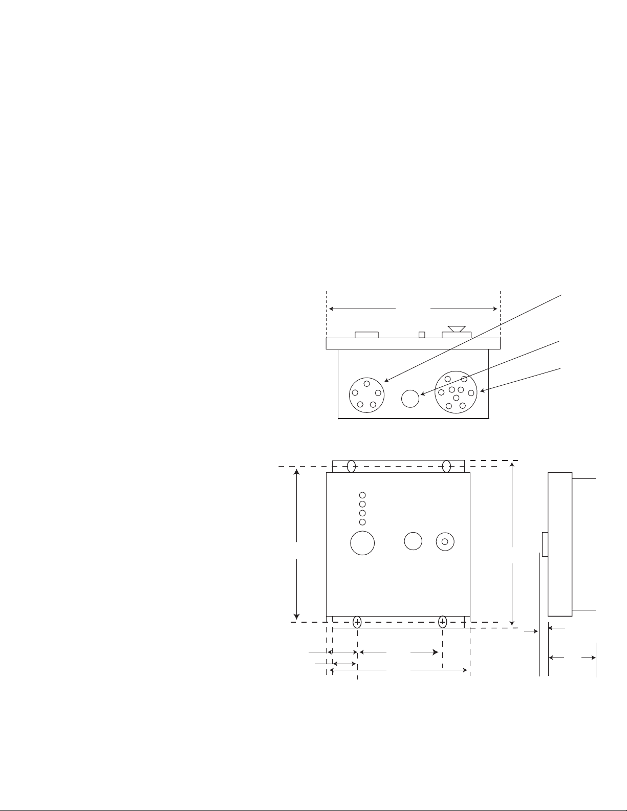
Refer to the dimensional diagram, Figure 1 for
actual mounting dimensions.
q 1. Select the location where the control will be
mounted. Insure that mounting will not
interfere with anything else and that wiring
access will not be impeded.
q 2. Using the dimensional information from the
diagram below, drill 4 mounting holes to
accept ¼-20 studs from the vibration
mounts for attaching the controller to
the machine frame.
q 3. Depending on the type of vibration
isolator mounts used, male to male or
male to female, attach one end of the
mount to the machine frame at all 4
10.500
points.
Note: For new installations where no wiring previously
exists, see the connector wiring diagram, Figure 4 for
pin/function descriptions.
5 Pin Socket
8.250
11.500
(Encoder)
Optional Hole
(Aux. Wiring)
9 Pin Socket
(CI-Bk/Power)
0.700
1.850
1.400
4.125
7.000
4.275
Figure 1
Dimensional Diagram
Warner Electric • 800-825-9050 P-291-1 • 819-0526 5
Page 6
Encoder Mounting & Installation
Normally, if the CBPC-3590 is replacing an existing
CBC1500-AHFC control, the encoder has already
been installed and set-up correctly.
new installations follow the procedure below
For
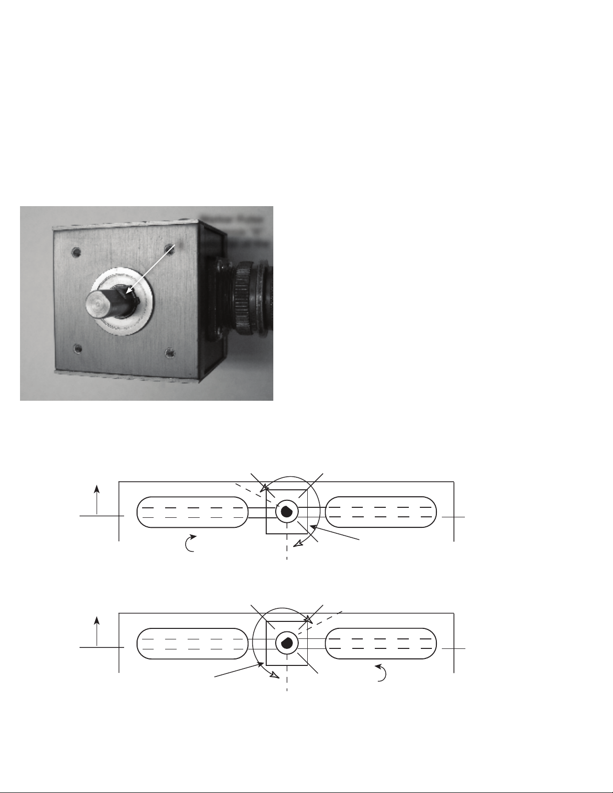
referring to gures 2 and 3 for correct encoder
mounting and positioning.
q 1. Taking the encoder, position the at on the
shaft to the position shown in Figure 2 below.
Marker Pulse
reference “X”
with at of the
X
shaft
q 2. Position the paddles on the pusher parallel to
the length of the pusher. This will be the position
the paddles are in when the pusher is static or not
rotating.
q 3. Determine if the pusher operates in a clockwise
(CW) or counter-clockwise (CCW) direction when
operating.
q 4. Mount the encoder with the bracket into the
pusher shaft keeping the shaft aligned in the
position as shown or as close as possible using
gures 3A or 3B for positioning the marker pulse
within the desired range.
q 5. Double check mounting and insure encoder is
fastened properly.
q 6. Connect encoder cable and tighten connector
securely.
q 7. This completes encoder mounting for new
application.
Figure 2
Encoder Marker Pulse Position Reference
Front
CW
Front
Ø
180
Note: Properly mounting the encoder in this method
insures the marker pulse will occur in the 50 to 450
pulse count range consistently. This is mandatory for
proper control operation.
90
270
180
Encoder
Marker Pulse Locating
Position 30° to 270°
Long Axis
Figure 3a
90
Ø
Long Axis
270
CCW
Marker Pulse Locating
Position 30° to 270°
Encoder
Figure 3b
6 Warner Electric • 800-825-9050 P-921-1 • 819-0526
Page 7

System Wiring
Figure 4 - Connector Pinouts and
Designations
Encoder Connector (5 Pin) Inside Wire Colors
Wiring the Warner Electric encoder
(6060-101-061) and cable to the connector
q 1. Route the encoder cable to avoid strains,
kinking and interference with mechanical
components.
Pin 1 – Encoder Signal “A” White
Pin 2 – Encoder +12 VDC Power Red
Pin 3 – Encoder Signal “Z” - Ref Green
Pin 4 – Encoder Signal “B” Orange
Pin 5 – Encoder DC Common Black
1
2
5
4
3
Power/Clutch-Brake Connector (9 Pin) Inside Wire Colors
Pin 1 – AC Start Signal (Hot 120 VAC) Orange/Black
Pin 2 – Channel 1 output (-) Brake Blue
Pin 3 – Channel 2 output (-) Clutch Red/Black
Pin 4 – Channel 2 output (+) Clutch Green/Black
Pin 5 – AC Power 120 VAC neutral line White
Pin 6 – AC Power 120 VAC hot line Red
Pin 7 – AC Earth Ground Green/Yellow
Pin 8 – Channel 1 output (+) Brake White/Black
Pin 9 – AC Start Signal (Neutral 120 VAC) Green/Black
q 2. Once cable has been routed and excess
length remains, cut the excess length off but
allow sufcient length for connection to
control. Strip the outer jacket to the
appropriate length for insertion of the wires
into the connector assembly.
q 3. Open the connector by removing the strain
relief nut and removing the rubber bushing
inside the housing. Snap the two halves of the
housing apart and separate from the header
connector.
q 4. Thread the encoder cable through the
strain relief nut and the rubber bushing pulling
enough cable through to strip and work on the
header and cable.
q a. Strip the cable jacket approximately ¾”
from the end of the wires.
q b. Strip the red lead (+12 VDC)
approximately ¼” and fasten to terminal 2 of
the connector and fasten securely.
Mating connector accessory are called out in the
specication section, Pages 3 and 4.
q c. Strip the black lead (DC Com)
approximately ¼” and fasten to terminal 5 of
7
1
6
the connector and fasten securely.
q d. Strip the orange lead (Signal A)
approximately ¼” and fasten to terminal 1 of
the connector and fasten securely.
2
5
q e. Strip the brown lead (Signal B)
approximately ¼” and fasten to terminal 4 of
8
3
9
4
the connector and fasten securely.
q f. Strip the green lead (Signal Z ref)
approximately ¼” and fasten to terminal 3 of
the connector and fasten securely.
Warner Electric • 800-825-9050 P-291-1 • 819-0526 7
Page 8

Note: This wiring is for clockwise (CW) opera-
tion. If during start up, the counter operates in the
reverse direction (that is, counter counts down
instead of up) or counter-clockwise (CCW)
operation is required, reverse the connections on
terminals 1 and 4 on external encoder connector
plug.
q 5. Reassemble the connector assembly by
snapping the two halves together over the
header connector. Slide the rubber bushing up
into the housing assembly and then thread the
strain relief grip onto the assembly snugly. The
outer jacket of the encoder cable should be
held by the strain relief grip.
q 6. This completes the wiring of the encoder
cable to the connector assembly using the
Warner encoder. If other than a Warner Electric
encoder is used, proceed to the next section
for wiring a different encoder.
Wiring other than the Warner Electric encoder
and cable assembly to the connector.
q 1. Route the encoder cable to avoid strains,
kinking and interference with mechanical
components.
q 2. Once cable has been routed and excess
length remains, cut the excess length off. Allow
sufcient length for connection to
control.
Strip the outer jacket to the appropriate
length (¾” typically) for insertion of the wires
into the connector.
q b. Determine which lead on the encoder
cable is the DC common and strip the lead
approximately ¼” and attach to terminal 5 of
the connector and tighten securely.
q c. Determine which lead on the encoder
cable is the Signal A and strip the lead
approximately ¼” and attach to terminal 1 of
the connector and tighten securely.
q d. Determine which lead on the encoder
cable is the Signal B and strip the lead
approximately ¼” and attach to terminal 4 of
the connector and tighten securely.
q e. Determine which lead on the encoder
cable is the Signal Z ref and strip the lead
approximately ¼” and attach to terminal 3 of
the connector and tighten securely.
Note: This wiring is for clockwise (CW) opera-
tion. If during start up, the counter operates in the
reverse direction (that is, counter counts down
instead of up) or counter-clockwise (CCW)
operation is required, reverse the connections on
terminals 1 and 4.
q 4. Reassemble the connector assembly by
snapping the two halves together over the
header connector. Slide the rubber bushing up
into the housing assembly and then thread the
strain relief grip onto the assembly snugly. The
outer jacket of the encoder cable should be
held by the strain relief grip.
q 5. This completes the wiring of the encoder
cable to the connector assembly.
q 3. Open the connector by removing the strain
relief nut and removing the rubber bushing
inside the housing. Snap the two halves of the
Connecting the encoder cable and power/
switching/and clutch-brake cables to the
controller.
housing apart and separate from the header
connector.
q 1. Connect the encoder cable connector by
locating the tab on the control male plug to the
q a. Determine which lead on the encoder
cable is the +12 VDC power and strip the
lead approximately ¼” and attach to terminal
2 of the connector and tighten securely.
tab on the encoder female connector and insert
and tighten securely. Do not force the female
connector into the male connector as damage
to the pins could occur if they are not properly
aligned. This is what the locating tab is for and
if connector tabs are properly aligned, they will
slide together easily.
8 Warner Electric • 800-825-9050 P-921-1 • 819-0526
Page 9

q 2. Determine if an interconnect cable with
connectors on each end will be used or a cable
with a connector on one end and pig tails
on the other end will be used for the power/
switching/and clutch-brake connections.
Note: If an intermediate switch disconnect panel
is used then typically wiring is done inside the
panel for interconnection of power, start signal,
and clutch-brake wiring. This will typically have a
connector for wiring to the controller.
q 3. Connect the interconnect cable connector
by locating the tab on the control male plug
to the tab on the cable female connector and
insert and tighten securely. Do not force the
female connector in the male connector as
damage to the pins could occur if they are
not properly aligned. This is what the locating
tab is for and if connector tabs are properly
aligned, they will slide together easily. Make
sure the connector on the other end at the
disconnect panel is connected and secured
properly.
Auxiliary Relay Wiring for Fault
Detection
for switching external circuits. Remember with
the control powered off, the normally open and
normally closed contacts will be reversed once
power is applied.
See Figure 6, page 10 for specic location of
terminal block.
q a. Typically the common contact and the
normally closed contact would be used to
control an external alarm or switching
circuit in the event of a fault condition.
q 4. This completes the wiring for the auxiliary
relay if used.
The control is now ready for commissioning.
Proceed to the Start-Up Section of the manual.
Start-Up
Start-up and calibration of this controller is much
simpler than the previous CBC1500-AHFC
controller in that most of the programming and
calibration steps associated with the previous
controller has been eliminated. Refer to Figure 5,
page 10 for switch locations.
The CBPC-3590 control was designed to provide
certain fault indications as well as providing an
interface to external control systems via an
internal relay. The relay activates on power up and
is designed to drop out in the event of a fault to
alert the user.
To wire the relay to an external control circuit
follow the steps below:
q 1. Remove the insert cover between the two
cable connectors on the CBPC-3590
controller. Refer to Figure 1, page 5.
q 2. Using a 3/4” seal tight connector, insert into
the conduit hold and securely tighten.
q 3. Wire the terminal block according to the
requirements of the system for contact
switching. The relay provides a common,
normally open, and normally closed contacts
q 1. Turn power on to the system and the
CBPC-3590 control. Push the power button on
the front of the controller and the red indica-
tor light on the power switch should illuminate.
The controller should power up with the brake
engaged and the front brake light LED
illuminated.
q 2. Place the front panel run/jog switch in the
jog position.
q 3. Push the front panel jog button until the
pusher paddles are in the proper home
position. This may require pushing the button
and cycling the load through a complete cycle
until the proper position is desired.
q 4. Once the paddles are in the desired home
position, place the front panel run/jog switch in
the run position.
Figure 5. Faceplate functions and Indicators
Warner Electric • 800-825-9050 P-291-1 • 819-0526 9
Page 10

Power Switch
Push - “ON”
Push - OFF”
Step 1
Run/Jog Switch
Up - “JOG”
Down - “RUN”
Step 2
Step 4
Jog Pushbutton
Step 3
q 5. Open the controller front cover. This will give
you access to the control board and the keypad/
display portion of the controller.
Refer to Figure 6, below, for internal display/keypad
and set up control functions.
q 9. Move the normal/set-up switch, to the
normal position.The “Normal” position is in the
down mode. The “Calibrate LED” should go out
at this time.
q 10. This completes the set-up and calibration
procedure for the control.
q 11. After calibration is complete, press the start
button on the display/keypad panel and the
control should cycle each time the switch is
pressed.
q 12. The display should be reading the count
position on each cycle and the load should be
returning to its home position each cycle.
Start Key
Step 8
Step 11
Reset/Clear Key
Step 6
Fault Relay
Terminal Block
Calibrate LED
On - “Calibrate”
Off - “Normal”
Normal/Set-up Switch
Up - “Set-up”
Down - “Normal”
Step 7
Step 9
Figure 6.
Internal Set Up Switches/Indicators
and Keypad/Display Layout
q 6. Press the reset/clear key on the keypad/
display.
q 13. Cycle the control about 5 to 6 times so that
the braking distance average will average out
correctly observing the stop point on the
counter. Close and latch the control.
If the pusher does not stop in the correct home
position after several start cycles, follow the
instructions below to resolve the problem.
q a. Press the RUN/PGM key on the keypad
q b. Enter 1, 0, 0, 0, and then press the down
arrow key once.
q c. The display should show “h” and some
number value.
q d. Insure the value displayed is between 50
and 450.
q e. If the value is outside the above range, the
encoder must be reset physically.
q 7. Move the normal/set-up switch to the set up
position. The set up position is with the lever in
q f. Follow the procedure below to reset the
encoder position.
the up position. In the set-up position the
Set-Up LED will illuminate.
Pusher must be disabled and
appropriate lock-out procedures
q 8. Press the start key on the keypad. The
controller will make one or more complete cycles
and stop.
Note: Once the calibration cycle has completed, the
paddles can stop in any location, not necessarily the
followed to
prevent accidental starts. Failure to do so could
result in system damage, injury or even death.
q 1. Loosen the encoder bracket and rotate
encoder at least 90 degrees.
home position.
10 Warner Electric • 800-825-9050 P-921-1 • 819-0526
Page 11

q 2. Re-tighten encoder bracket securely.
q 3. Proceed to step 1 of the start-up procedure,
page 9 to recalibrate the system.
Note: If in doubt about encoder positioning, refer to
new encoder installation procedure, page 6.
If unit has problems such as “windmilling” program
default needed, do the following steps:
q a. Press the RUN/PGM key on the keypad.
q b. Enter 1, 0, 0, 0 and then press the down arrow
repeatedly until the end display reads: “t8.rdy”.
q c. Press the arrow right button.
q d. Press the RUN/PGM key.
q e. Proceed to step 1 of the start-up procedure
on page 9 to recalibrate the system.
This completes the installation and set-up of the
CBPC-3590 control. Close and latch the control
securely.
As the controller has been designed as an improved
version of the CBC1500-AHFC with additional
features and improved performance and reliability,
programming of the various parameters should only
be accomplished by qualied personnel.
To Enter the programming mode, follow the steps
below:
Open the controller front cover for access to the
keypad/display. Press the RUN PGM key on the
keypad/display
Display will show LOC. 0
Then press 1, 0, 0, 0
Display will show LOC. 1000
This has now placed you in the programming mode
where various parameters can be changed by using
the down arrow key to increment through the various
parameters.
Programming Functions:
Default Settings
Default
Press Display Value Function
↓ h xxx -- Home Position
↓ bd. xx -- Brake Distance, PPR
↓ bdAue. 3 3 Cycles Averaged
↓ cc. 0.5000 0.5000 Count Correction
↓ dP. oFF oFF Decimal Point
↓ FrSt. oN oN Front Panel Reset
↓ PLoc. oFF oFF Panel Lock
↓ CrEt. oFF oFF Count Retention
↓ ArSt. oN oN Auto Reset
↓ o1. 0.20 0.20 Start Signal, ms
↓ o2. 0.01 0.01 Early Warning, ms
↓ o3. 0.20 0.20 Stop Signal, ms
↓ o4. 0.10 0.10 Zero Speed, ms
↓ o5. 0.05 0.05 Zero Speed + delay 1, ms
↓ o6. 0.05 0.05 Zero Speed + delay 2, ms
↓ o8. LatCH LatCH Batch Auto Reset
↓ d1. 0.10 0.10 Delay 1, ms
↓ d2. 0.01 0.01 Delay 2, ms
↓ 05P .25 .25 Zero Speed Window, sec
↓ 5 -.-.-.-.-.-. -.-.-.-.-.-. Start Release
↓ L -.-.-.-.-.-. -.-.-.-.-.-. Move Preset Release
↓ E -.-.-.-.-.-. -.-.-.-.-.-. Early Warning Release
↓ r -.-.-.-.-.-. -.-.-.-.-.-. Reset Release
↓ bd. OFF OFF Baud Rate
↓ Par. None None Parity
↓ PFr. 80 80 Output Frequency, Hz.
↓ cPr. 90 90 Clutch Output Percentage
↓ bPr. 75 75 Brake Output Percentage
↓ JPr. 40 40 Jog Output Percentage
↓ cBt 15 15 Clutch Boost Percentage **
↓ bBt 40 40 Brake Boost Percentage **
↓ Id.no. xxx xxx Unit Number (Up to 3 digits)
↓ t0. rdy rdy Keyboard test
↓ t1. rdy rdy RAM test
↓ t2. rdy rdy Inputs test
↓ t3. rdy rdy Outputs test
↓ t4. rdy rdy Display test
↓ t5. rdy rdy Memory test
↓ t6. rdy rdy Date Code
↓ t7. rdy rdy Serial Test
↓ t8. rdy rdy Reset Default Program
** Only when the OEX add-on board is installed in the CBPC-3590 are
these two functions active and operational for programming.
Warner Electric • 800-825-9050 P-291-1 • 819-0526 11
Page 12

Pressing RUN PGM Key exits the programming
mode and returns the display for normal count
function.
RUN PGM CNT xxx
Often problems encountered by the CBPC-3590 can
be resolved by resetting the control or resetting the
program to its default settings.
To reset the controlller:
q 1. Turn off power via the front panel power
switch.
q 2. Wait 5 seconds or more.
q 3. Turn power back on to the control.
To reset the program to the original default values,
follow the steps below.
RS-485 Hook Up and Programming
The CBPC-3590 Control was designed to accept an
RS-485 serial interface connection for programming
and data collection. Keypad and some external
control inputs are supported. Additionally, facilities
are provided for individual (local) and group (global)
control of single and multiple unit congurations
respectively. Knowledge of serial communications
and the ASCII data format is required by the user
who wishes to use the remote capabilities or to
integrate the control into a larger system.
Two applications will be discussed. The rst consists of a single CBPC-3590 and a display termi-
nal. It explains the use of the serial commands
that mimic the keypad operation and some control
inputs. These are the LOCAL commands. Next, an
application of multiple units under the control of a
host computer will be discussed. The GLOBAL
commands will also be discussed in this section.
q 1. Press the RUN PGM key
Display will show LOC. 0
q 2. Enter 1,0,0,0
Display will show LOC. 1000
q 3. Using the down ↓ key, scroll down until the
display shows t8. rdy
q 4. Using the right → key, change the display to
show t8. run
q 5. Press the RUN PGM key to exit the
programming mode.
Display will show CNT xxx
This completes the program reset function.
Note: After resetting program, control must be
recalibrated.
12 Warner Electric • 800-825-9050 P-921-1 • 819-0526
Page 13
RS232 to
RS422/485
Converter
RXD
COM
TXD
TXD+
TXD-
SHLD
RXD-
RXD+
Display/Keypad
CBPC-3590
Twisted Pairs with Shields
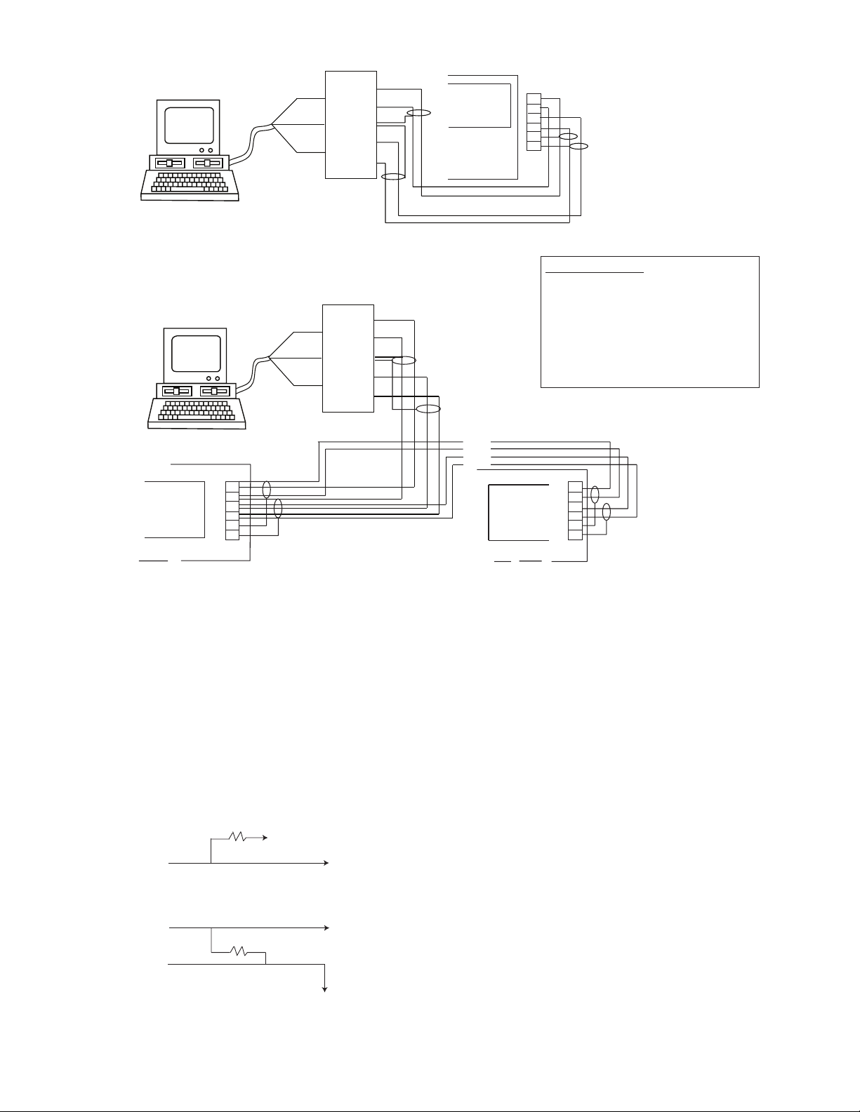
Figure 7a Single Unit Wiring
RS232 to
RS422/485
Converter
RXD
COM
TXD
TXD+
TXD-
SHLD
RXD-
RXD+
J4
6
5
4
3
2
1
J4 Connections
Pin 6 TXD+
Pin 5 TXD-
Pin 4 RXD-
Pin 3 RXC+
Pin 2 Shield to Chassis End
Pin 1 Shield to Chassis En
d
J6
Keypad/Display
CBPC-3590
6
5
4
3
2
1
Figure 7b Multiple Unit Wiring
Termination
The RS-422A/485 receivers require termination to
minimize the effects of noise while the bus is not
being driven. The CBPC-3590 incorporates the
terminations shown below internally. When
connection is made to a RS-422/485 device other
than the CBPC-3590, the receiver should be
terminated as shown.
+5V
TXD+
from
CBC-1000
TXD-
2
10 k Ω max. to
100 Ω min.
to
receiver
} {
J4
Keypad/Display
CBPC-3590
Cable Selection
The CBPC-3590 serial interface uses a simple
interconnect scheme and low cost wiring mak-
ing it superior to parallel data transfer schemes.
Through two (2) wire shielded pairs, remote
operation at distances up to 5,000 feet can be
implemented. The following general guidelines
should be observed.
1. Use # 24 AWG twisted pair, overall shielded
cable.
2. Use a “daisy chained” connection scheme for
bus systems.
6
5
4
3
2
1
3. If a “multidrop” system is used, keep the drop
COM
length at 10% of the main line.
4. Tie the cable shield to the Building Ground at
the CBPC-3590 end of the cable.
Warner Electric • 800-825-9050 P-291-1 • 819-0526 13
Page 14

Single Unit Operation
The operator can monitor the control locally via
the keypad and display located inside the control
housing. The serial interface extends these
monitoring activities to a remote location. The
connection of a remote display terminal is
straightforward. The ID number of the control
should be set to “0” (line 32 in the program table).
When power is applied to the CBPC-3590 control,
it will start a continuous serial transmission of the
count:
CBPC-3590 R: CNT. 123456
when in the run mode.
The function keys (1,2,3,6,7, & 8) are used to scroll
down through the eight RUN mode lines. For
example:
terminal ‘1’ CBPC-3590 R: CNT. 123456
terminal ‘2’ CBPC-3590 R: Mov.Pst. 600
terminal ‘3’ CBPC-3590 R: E.W. 50
terminal ‘6’ CBPC-3590 R: BCH. 100
terminal ‘7’ CBPC-3590 R: BCH.Pst. 0
terminal ‘8’ CBPC-3590 R: Bd. 25
In the RUN mode, the numbers 1,2,3,6,7, & 8
cause new lines to be transmitted.
The control remains active (in the RUN mode)
until the proper LOC combination is entered. Each
numeric entry is entered from right to left
“calculator style”. The character sequence
1-0-0-0 would produce the following display on
the terminal:
terminal ‘1’ CBPC-3590 R: LOC. 1
terminal ‘0’ CBPC-3590 R: LOC. 10
terminal ‘0’ CBPC-3590 R: LOC. 100
terminal ‘0’ CBPC-3590 R: LOC. 1000
When this combination is correctly entered with
the down cursor (‘D’ character), the control exits
the RUN mode and enters the PROGRAM mode
and returns with the following.
terminal ‘D’ CBPC-3590 P: h. ---
Note that the PROGRAM (‘P’) prompt is now
shown. You are at the top of the PROGRAM table
(line 1) as shown on page 11. Once the
PROGRAM mode has been entered it is pos-
sible to program any line in the table. Refer to the
COMMAND CHARACTER table for keypad
equivalent serial characters. A programming
example is shown below:
terminal ‘C’ CBPC-3590 P: Mov.Pst. 000
terminal ‘6’ CBPC-3590 P: Mov.Pst. 6
terminal ‘0’ CBPC-3590 P: Mov.Pst. 60
terminal ‘0’ CBPC-3590 P: Mov.Pst. 600
We have now seen how the CBPC-3590 control
works for remote viewing; we will now see how
programming may be done from a remote location.
You may program only one CBPC-3590 control
at a time. If the unit is in the program mode via
the keypad then it will not respond to the serial
input. To enter the PROGRAM mode you must rst
send the RUN/PGM (“P”) character. The control
will “answer” by transmitting the LOC entry line as
shown below:
terminal ‘P’ CBPC-3590 R: LOC 0
14 Warner Electric • 800-825-9050 P-921-1 • 819-0526
The rst serial entry (‘C’) clears the data eld for
the current line. As can be seen in the COMMAND
CHARACTER table, this character mimics the
RESET/CLEAR key. Numeric data entry is
self-explanatory.
Multiple Unit Operation
For multiple unit systems (up to 999) a special
addressing scheme is implemented in order that
no conicts arise on the serial bus. Each unit is
given a unique address (ID number entered on line
32). Such a system application is shown on page
16. All units are programmed with the same baud
rate and parity. It is advised that the initial ID
number programming be done before the units
are bussed together.
Page 15

To control one CBPC-3590 in a bus oriented system the host must rst address it by sending an
ADDRESS COMMAND SEQUENCE. This is shown
below:
host: (ESC) A nnn (where nnn is the unit
number from 1 to 999)
This escape code sequence will suspend the
transmission from all units including the one that is
addressed. The addressed unit will respond to all
subsequent commands while the other units just
“listen” on their receive input and turn their transmit
output off.
To receive data from an addressed unit the host
sends it a command to resume transmission using
the RESUME control character, (CTRL Q).
Remote Operation
Some of the unit’s CONTROL inputs are
effectively duplicated by serial commands, so it is
possible to implement a single or multiple unit
system with remote capability. Such a system can
be used for multiple machines. Keep in mind the
addressing requirements for multiple unit systems
previously discussed.
Two types of commands are available, LOCAL
and GLOBAL. LOCAL commands affect only the
unit that is currently addressed. GLOBAL com-
mands on the other hand affect all units regardless
of address. In this way it is possible to command
many units to begin control at the same point in
time. The table below lists the LOCAL and GLOBAL
commands that are supported.
If you wish to suspend data transmission you may
do so by using the SUSPEND control character,
(CTRL S).
In some cases the host may want to send many
commands to a CBPC-3590 control without waiting
for responses. This may be done by rst suspending
transmission (CTRL S) then by requesting a single
UPDATE.
host: (ESC) U
Setup Mode Operation
The SETUP mode may be entered directly from the
RUN mode by cursoring to the desired SETUP lines
(4 – 8) using the ‘D’ command character then
sending the ‘L’ command character which mimics
the KEY keypad key. This action will place the
control in the SETUP mode allowing the user to
change the data in lines 3 through 8 in the program
table. Refer to page 11 for a complete operational
description.
Preset setpoints are changed using the numeric,
RST/CLR and DOWN cursor keys. The SETUP mode
is exited by sending another ‘L’ command character
at which time the controls reverts back to the RUN
mode.
Local and Global Commands
Control
Commands Local Global Comments
Control (ESC) LO (ESC) GO Simulates Output
Output Control Input
Batch (ESC) LB (ESC) GB Resets Batch
Reset to zero
Counter (ESC) LR (ESC) GR Resets Counter
Reset to zero
Formats and Protocol
Character Format
The serial interface sends and receives
information by characters consisting of 10 bits. The
RS422A/485 interface requires a 0.2 V minimum
differential across the + and – terminals. A logic
high (mark) is a positive differential and a logic low
(space) is a negative differential.
Note: Connection to EIA-422/485 equipment that
uses the opposite polarity requires swapping the +
and – connections at the other equipment.
Warner Electric • 800-825-9050 P-291-1 • 819-0526 15
Page 16

The character format is as follows:
(sp)(sp) (sp) (cr)(cr) R : Co . 12 3 . 45 6
ʻSʼ
“U”
ʻCʼ
“Q”
ʻDʼ
thru
ʻEʼ
ʻRʼ
ʻPʼ
ʻ0ʼ THRU ʻ9ʼ
RUN
PGM
EDITSTOP
0
START
RESET
CLEAR
(sp)(sp) (sp) (cr)(cr) R
:
Co . 12 3 . 45 6
Start bit (“low” logic level)
ASCII data (7 bits), least to most signicant
Parity bit (programmable)
Stop bit (“high” logic level)
HIGH
LOW
SD0D1D2D3D4D5D6P S
Parity Bit
The parity bit is programmable as “Odd,” “Even,”
or “No” parity. Odd and Even parity force the total
number of data bits to be an even or odd for data
that is transmitted by the CBPC-3590 control.
Incoming parity is always compared to the
calculated parity. Characters with parity errors are
discarded. If No parity is selected incoming parity
is ignored. Characters are transmitted with Odd or
Even parity as selected on line 25 of the program
table. If No parity is selected then “high” bit is
added as an extra stop bit.
Baud Rate
Select the baud rate to match the device
communicating with the control. You may select:
300, 600, 1200 or 2400 baud on line 24 of the
program table. Baud rate is common to both
transmitter and receiver.
Line Format
The CBPC-3590 control transmits only complete
lines. The driver is turned off when not
transmitting causing the bus to enter a “oat”
state, ignoring data on the bus during this “oat”
time. Unless otherwise commanded the
CBPC-3590 control continuously transmits the
Count Value. The line format is as follows:
Note: To make changes in Parity or Baud Rate
power must rst be removed and reapplied after
program changes to either are made. Both Parity
and Baud Rate are initialized when the control
“powers up”.
Command Characters
Command Characters mimic the operation of the
keypad. Below is a list of the serial equivalents of
the keypad keys.
RUN
START
RESET
CLEAR
ʻSʼ
“U”
ʻCʼ
ʻEʼ
“Q”
ʻDʼ
thru
0
EDITSTOP
ʻRʼ
ʻ0ʼ THRU ʻ9ʼ
PGM
ʻPʼ
Control Characters
Two control characters are used to start and stop
the transmission from the CBPC-3590 control.
They are shown below:
(CTRL) S Suspends transmission following
the completion of a line being sent.
The driver will then be turned Off.
(CTRL) Q Resumes transmission from a unit
that had been turned Off. The RUN
mode line currently selected will be
continuously updated.
- a carriage return at the beginning of a line
- a prex indicating RUN, SETUP, or PROGRAM
- a unique line mnemonic
- a ve digit data eld with decimal point
- a carriage return at the end of the line
:
16 Warner Electric • 800-825-9050 P-921-1 • 819-0526
Co . 12 3 . 45 6
(sp)(sp) (sp) (cr)(cr) R
Page 17

Escape Code Sequences
Escape code sequences are a group of special
commands used for bus oriented systems. Every
CBPC-3590 control recognizes these commands.
The two listed below are in addition to those
listed in the table of LOCAL and GLOBAL
commands.
(ESC) A nnn The Address command is used
to select a single control within a
system. Only that unit whose
serial I.D. number matches the
three digit serial address (nnn)
will be selected. Only that unit
will respond to subsequent
serial commands. All units, even
the addressed one, suspend
transmission.
(ESC) U The Update command instructs
the currently addressed unit to
transmit a single line only.
Protocol
The CBPC-3590 will “buffer” up to 16 Command
and Control Characters (but not Escape Code
Sequences), listed above, sent in “burst mode”.
Those characters are read, in order, every 20
milliseconds. The protocol should be careful
not to overow the receive buffer. Additionally,
Escape Code Sequences should not be sent until
the buffer has emptied and all characters have
been processed.
Warner Electric • 800-825-9050 P-291-1 • 819-0526 17
Page 18

Troubleshooting
Only Authorized Personnel to Set Up and Maintain this Unit.
The CBPC-3590 control has several internal diagnostic features that illuminate an indicator light showing
fault condition and a fault indication on the display. Once a fault condition occurs, the control has to be
opened to access the display panel and read the fault condition. Not every fault that is possible will be
displayed with an indication, only the most prevalent ones.
The following conditions will cause the front panel fault LED to illuminate and the fault relay internal to
the control to drop out.
Fault Display Corrective Action to be Taken
Low Voltage Lo Volt After normal voltage is restored, unit
returns to normal operation.
Red fault LED “On”
Fault Relay drops out
Feedback too fast Error 2 Reset clears fault.
Speed or encoder resolution must be reduced
Red fault LED “On” or corrected to prevent further errors.
Fault Relay drops out
Process time fully Error 3 Reset clears fault.
utilized Speed or encoder resolution must be
Red fault LED “On” reduced or corrected to prevent further
Fault Relay drops out errors.
Additionally, other faults can occur with the CBPC-3590 which can effect the operation of the system. Some common
faults that could occur are listed below.
Fault Possible Cause Solution
Count direction negative Encoder signals “A” and Reverse signal “A” and “B” wiring on
rather than positive “B” reversed encoder connector plug.
Unit does not start when Start signal voltage Check switching voltage on start input
external start signal is incorrect or not present line (120 VAC) or make sure start switching
applied circuit is functional.
If system will start with start key on keypad,
then fault is external to the control.
Control does not operate No power to control Check that power light in “On/Off” switch is
turned on.
Check that the AC power is applied to control
at control cable.
Check fuse.
Check that “On/Off” power switch is turned on.
Clutch-Brake not connected Check that the clutch-brake is mounted and
connected to output of control.
Cables are not connected Check that both encoder cable and power/
to control CI-Bk cable is connected to controller.
18 Warner Electric • 800-825-9050 P-921-1 • 819-0526
Page 19

Fault Possible Cause Solution
Unit does not stop Brake not completely Cycle unit several hundred cycles to
accurately burnished burnish brake properly.
Not enough cycles Cycle unit several times to get braking
completed to get average distance calculation based on average
braking distance calculation number of cycles set point.
Unit does not stop at all Unit is not getting encoder Check that encoder is providing both “A”
signals and “B” signals to the control.
Check that encoder is providing “Z” pulse by
checking that home indicator LED ashes every
360 degree cycle.
Check that Z signal (home position) marker pulse
is between 50 and 450 counts. See “h” on
programming setup, page 11.
Stop point varies from Brake output level set Set output level to brake higher by entering
cycle to cycle too low program mode and going to line 28 in
programming mode and increasing output level.
Brake is possibly worn out Check number of cycles on brake and
replace if worn excessively.
Count jumps when system Electrical noise being Determine source of electrical noise and
is at standstill generated and coupled to suppress appropriately.
control via wiring or air
Reroute control wiring if necessary and isolate
power and signal lines.
Excessive vibration on Check encoder mounting and isolate if
machine necessary.
During start, clutch does Clutch output level set too Set output level to clutch higher by entering
not seem to have enough low program mode and going to line 27 in
torque to drive load programming mode and increasing output level.
Clutch is new and has not Cycle clutch until burnish is obtained.
been burnished as yet Number of cycles will be dependent on
loading.
Clutch is possibly worn out Check number of cycles on clutch and
replace if worn excessively.
By no means does this cover every possible fault that could be encountered with the control and
clutch-brake. This is only a basic overview of the more common faults that occur with the control. If a
specic problem is encountered that cannot be resolved the best solution is to contact your local Warner
Electric Distributor, Representative, or the factory for further assistance in resolving your problem.
Warner Electric • 800-825-9050 P-291-1 • 819-0526 19
Page 20

Notes and Set Up Information
20 Warner Electric • 800-825-9050 P-921-1 • 819-0526
Page 21

Warner Electric • 800-825-9050 P-291-1 • 819-0526 21
Page 22

Warranty
Warner Electric LLC warrants that it will repair or replace (whichever it deems advisable) any product manufactured and sold
by it which proves to be defective in material or workmanship within a period of one (1) year from the date of original purchase
for consumer, commercial or industrial use.
This warranty extends only to the original purchaser and is not transferable or assignable without Warner Electric LLC’s prior
consent.
Warranty service can be obtained in the U.S.A. by returning any defective product, transportation charges prepaid, to the
appropriate Warner Electric LLC factory. Additional warranty information may be obtained by writing the Customer Satisfaction
Department, Warner Electric LLC, 449 Gardner Street, South Beloit, Illinois 61080, or by calling 815-389-3771.
A purchase receipt or other proof of original purchase will be required before warranty service is rendered. If found defective
under the terms of this warranty, repair or replacement will be made, without charge, together with a refund for transportation
costs. If found not to be defective, you will be notified and, with your consent, the item will be repaired or replaced and
returned to you at your expense.
This warranty covers normal use and does not cover damage or defect which results from alteration, accident, neglect, or
improper installation, operation, or maintenance.
Some states do not allow limitation on how long an implied warranty lasts, so the above limitation may not apply to you.
Warner Electric LLC’s obligation under this warranty is limited to the repair or replacement of the defective product and in no
event shall Warner Electric LLC be liable for consequential, indirect, or incidental damages of any kind incurred by reason of
the manufacture, sale or use of any defective product. Warner Electric LLC neither assumes nor authorizes any other person
to give any other warranty or to assume any other obligation or liability on its behalf.
WITH RESPECT TO CONSUMER USE OF THE PRODUCT, ANY IMPLIED WARRANTIES WHICH THE CONSUMER MAY
HAVE ARE LIMITED IN DURATION TO ONE YEAR FROM THE DATE OF ORIGINAL CONSUMER PURCHASE. WITH
RESPECT TO COMMERCIAL AND INDUSTRIAL USES OF THE PRODUCT, THE FOREGOING WARRANTY IS IN LIEU OF
AND EXCLUDES ALL OTHER WARRANTIES, WHETHER EXPRESSED OR IMPLIED BY OPERATION OF LAW OR
OTHERWISE, INCLUDING, BUT NOT LIMITED TO, ANY IMPLIED WARRANTIES OF MERCHANTABILITY OR FITNESS.
Some states do not allow the exclusion or limitation of incidental or consequential damages, so the above limitation or
exclusion may not apply to you. This warranty gives you specific legal rights and you may also have other rights which vary
from state to state.
Changes in Dimensions and Specications
All dimensions and specifications shown in Warner Electric catalogs are subject to change without notice. Weights do not
include weight of boxing for shipment. Certified prints will be furnished without charge on request to Warner Electric.
P-291-1 • 819-0526 5/12
Warner Electric
449 Gardner Street • South Beloit, IL 61080 - USA
800-389-3771 • Fax: 815-389-2582
www.warnerelectric.com
Printed in USA
 Loading...