

Page 1
AC Rectier CBCx-001
Installation & Operation Manual
P-2100-WE
CBCx-001
An Altra Industrial Motion Company
Page 2
2 Warner Electric • 800-825-9050
P-2100-WE • CBCx-001
Function
The CBCx-001 power supply is an AC rectifier providing
a time programmable Over-excitation voltage as well as
an integrated On/Off switch. This is particularly suitable
to all Power-Off applications based on our well known
Elevator Brakes, ERD or ERS brakes.
The Over-excitation feature is automatically switching
from a Full bridge to a single wave rectification after a
programmable time (from 50 ms up to 4 s). It can easily
be disabled to convert your power supply in a Single
or Double wave rectifier. The On/Off Control allows this
power supply to be driven directly thru an external PLC
or Control board. Thanks to its integrated PNP input,
the power can be directly applied or removed without
using any external Switches or Relays. The DC poweroff feature associated to the state of the art snubber
design allows drastic reduction of the engagement time
requested by most of the security related applications.
Ratings
Input Voltage
100 VAC to 500 VAC
(+/- 10%) 50 – 60 Hz
Output Voltage 90 VDC to 450 VDC
Maximum Output
Current
5 Amps max
(See below conditions)
Over-Excitation
Integrated programmable timer
(from 50 ms to 4 s)
ON/OFF Control
Integrated PNP Input (8 to 30 VDC).
(can be disabled)
Shorter
Response time
DC switch off
Integrated back EMF suppression
Certications CE, UL approved
Operating T°C
-25°C to 70°C no Condensation
(Check below instructions for more
details)
Compliance
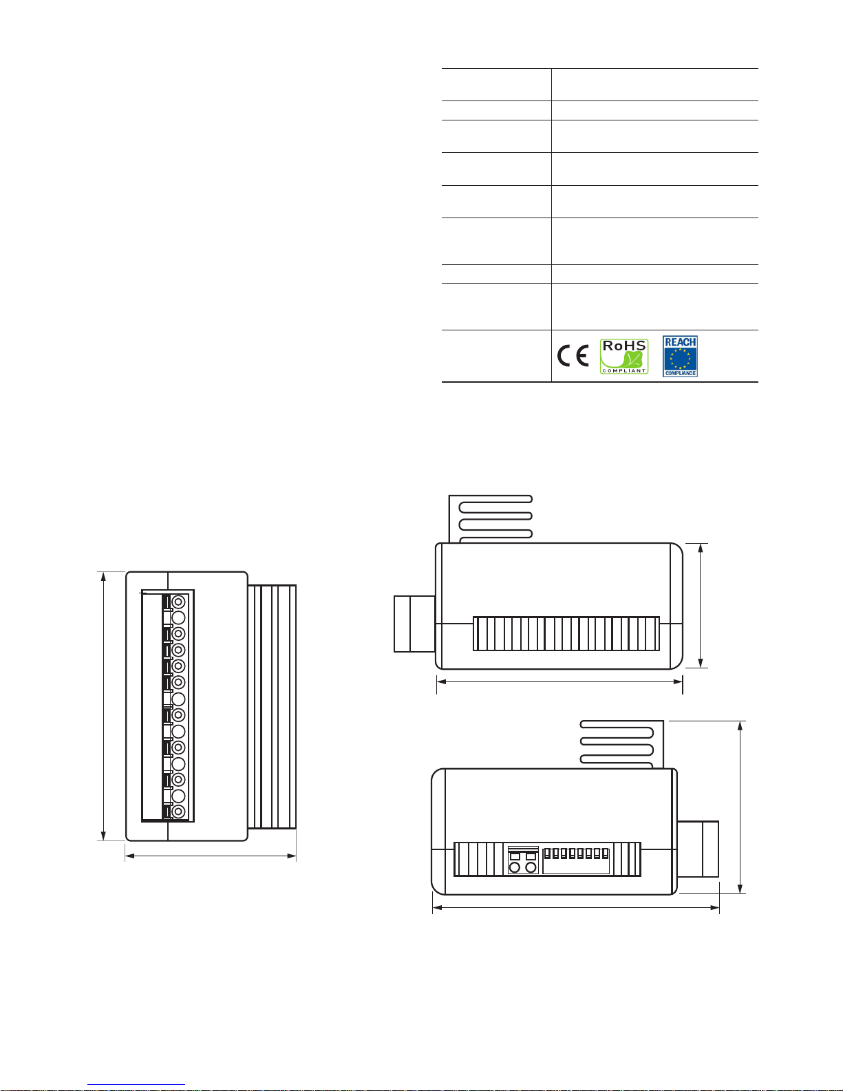
FREIN+
FREIN-
SHUNT
SHUNT
SWITCH+
SWITCH-
AC
AC
PE
83
53
+
+
+
75
38
1 2 3 4 5 6 7 8
OFF
LOGIC CONTROL
DIP SWITCH
24VDC
+ -
88
53
Page 3

Warner Electric • 800-825-9050
P-2101-WE • CBCx-001 3
General information
Power supply enclosure should be kept clear of all
areas where foreign material, dust, grease, or all
might affect the operation of the control.
Installation must be made in accordance with the
instructions found in this manual. Failure to do so
may damage the Power supply.
Electrical Connection
1 DC BRAKE + Power Output Output contact to the Clutch/Brake Coil. DC Power output : 90 VDC to 450 VDC.
2 DC BRAKE - Power Output Output contact to the Clutch/Brake Coil.
3 SHUNT+ Accessory
Current Sensing.
Contact which allows the opening of the power supply DC Side to integrate a current
sensing or over measuring instrument. One can add a Hall effect current probe for
instance.
Default : When not used, a Short circuit bridge is needed between pins 3 and 4.
4 SHUNT- Accessory Current Sensing.
5 DC SWITCH + Accessory
DC switching off.
Use to Power off the brake with a Fast Response Time : Emergency stop for
instance.
Default : When not used, a Short circuit bridge is needed between pins 5 and 6.
6 DC SWITCH - Accessory DC switching off.
7 AC Power Input AC power Input : 90VAC to 500VAC
8 AC Power Input AC power Input : 90VAC to 500VAC
9 PE Protective Earth This terminal is usually connected to earth provided by the AC grid.
Logical
Control 1ON/OFF + Digital input
Logic Control. 24V PNP input. When High, powers up the brake. This power up will
be made on the AC side, with offering
If over-excitation feature is enabled, then over-excitation voltage is applied during the
programmed time.
Active High/GND: PNP type Input.
Logical
Control 2Ground Digital input Ground
Page 4

4 Warner Electric • 800-825-9050
P-2100-WE • CBCx-001
Synoptic:
Technical Data
Input Voltage 100 VAC to 500 VAC (+/- 10%) 50 – 60 Hz
Output Voltage 90 VDC to 450 VDC
With Over-excitation U
Brake
(VDC) = 0,9 x UAC (Limited to the selected over-excitation time)
Full Wave U
Brake
(VDC) = 0,9 x U
AC
Half Wave (Holding voltage) U
Brake
(VDC) = 0,45 x U
AC
Max T °C
Output Current 70°C 2 Amps Over-excitation (double Wave) / 1 Amps Holding (Single Wave)
60°C 3 Amps Over-excitation (double Wave) / 1.5 Amps Holding (Single Wave)
50°C 5 Amps Over-excitation (double Wave) / 2.5 Amps Holding (Single Wave)
AC Input:
100 to 500 VAC
On/Off Switch
(AC Side)
Output
Voltage suppression
Over-Excitation
DIP4-7: Programmable Over-Excitation Time:
50ms to 4000ms.
DIP3: Diable
Full Wave
DIP2: Enable
Bridge Rectier
DC Switch OFF Shunt
Logic Control
(PNP type)
DIP1: Disable
Page 5

Warner Electric • 800-825-9050
P-2101-WE • CBCx-001 5
DIP Switch selection
+
1 2 3 4 5 6 7 8
OFF
ON
LOGIC CONTROL
DIP SWITCH
24VDC
+ -
DIP1 if ON PNP Logic control input disabled
DIP2 if ON Full Wave forcing
If ON, Over-excitation is always enabled.
DIP3 if ON Over-excitation Disabled
50ms 100ms 150ms 500ms 1000ms
(Default)
1500ms 2000ms 3000ms 4000ms
DIP4 ON ON ON ON ON ON ON
DIP5 ON ON ON ON ON
DIP6 ON ON ON ON
DIP7 ON ON ON ON ON ON
DIP8 Not used
Examples
AC switching with external contactor (not supplied) / 24VDC PNP Control not used / 1s Over-excitation:
DIP1: ON DIP2: OFF DIP3: OFF DIP4: ON DIP5: ON DIP6: OFF DIP7: ON
24VDC PNP Control Enabled / 500ms Over-excitation:
DIP1: OFF DIP2: OFF DIP3: OFF DIP4: ON DIP5: ON DIP6: ON DIP7: ON
AC switching with external contactor (not supplied) / 24VDC PNP Control not used /
Full wave control (no Over-excitation):
DIP1: ON DIP2: ON DIP3: NA DIP4: NA DIP5: NA DIP6: NA DIP7: NA
AC switching with external contactor (not supplied) / 24VDC PNP Control not used / Half wave control :
DIP1: ON DIP2: OFF DIP3: ON DIP4: NA DIP5: NA DIP6: NA DIP7: NA
Installation
1 DC BRAKE +
2 DC BRAKE -
3 SHUNT+
4 SHUNT-
5 DC SWITCH +
6 DC SWITCH -
7 AC
8 AC
9 PE
Brake
Measuring loop
- If not used, please Short Circuit 3 & 4 -
Fast Response time Switch OFF.
- If not used, please Short Circuit 5 & 6 -
Protective circuit
(FF 5 Amps)
Connected to the Grid
100 VAC to 500 VAC (+/- 10%)
50 – 60 Hz
Page 6

www.altramotion.com
An Altra Industrial Motion Company
P-2100-WE 9/14 Printed in USA
www.warnerelectric.com
7, rue Champfleur, B.P. 20095
St Barthelemy d’Anjou - France
+33 (0)2 41 21 24 24
Fax: +33 (0)2 41 21 24 70
 Loading...