

Page 1
CBC-750 Series Clutch/Brake Controls
P-270
819-0494
Installation & Operating Instructions
Page 2
Introduction
Warner Electric’s CBC-750 Series of Constant
Current Overexcitation Clutch-Brake Controls
are solid-state electronic controls designed to
increase the cycle rate capabilities and accuracies
of electromagnetic clutches and brakes. The controls
accomplish this by sending a momentary high
voltage overexcitation spike to the clutch and/or
brake magnetic coil to build a high density magnetic
flux field almost instantaneously. By using overexcitation, the response time is reduced as dramatically
as performance is increased. For example, the
current build up time of a 5 inch, 6 volt magnet is
reduced from 84 milliseconds to 2 milliseconds.
The CBC-750 user selects either 120, 220, or 240 VAC
operation at the time of installation. Models with 6
volt, 24 volt, or 90 volt clutches and brakes are
available.
LED indicators on the faceplate of each control
tell the user the status of input signals, output
activation and any auxiliary inputs. A reset switch
resets the output should a short be detected.
Remote torque adjust potentiometer inputs are also
provided. Appropriate current range for each size
clutch or brake is selected by a dip switch. Constant
current for each level is assured by the control’s
design
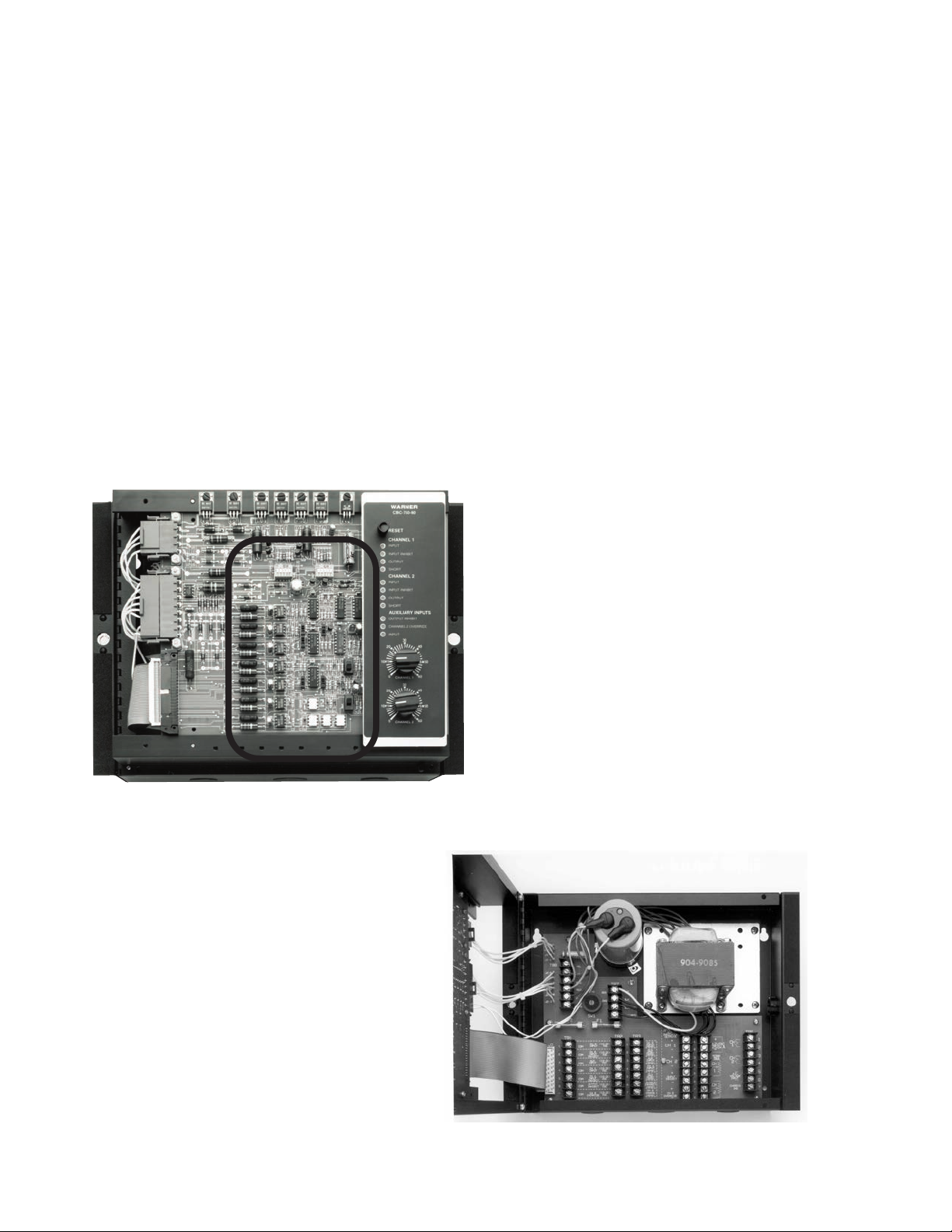
The CBC-750 printed circuit
board and control panel are
shown here. The seven individual
function switches and two range
switches evident in this photo
are detailed in Figure 8, page 10.
Releasing the lock pins and lifting the
top cover reveals the CBC-750’s lower
level where wire connections are
made. Schematic versions of these
terminal boards are found in this
manual on pages 8-10.
Warner Electric • 800-825-9050 819-0494
2
Page 3

Contents
Introduction . . . . . . . . . . . . . . . . . . . . . . . . . . . . . 2
Theory of Operation . . . . . . . . . . . . . . . . . . . . . . 3
Technical Specifications . . . . . . . . . . . . . . . . . . . 4
Installation . . . . . . . . . . . . . . . . . . . . . . . . . . . . . . 5
System Wiring
Wiring Precautions . . . . . . . . . . . . . . . . . . . . . 6
AC Input Power. . . . . . . . . . . . . . . . . . . . . . . . 7
Clutch-Brake Wiring . . . . . . . . . . . . . . . . . . . . 7
Switching Inputs . . . . . . . . . . . . . . . . . . . . . . 8
Auxiliary Outputs . . . . . . . . . . . . . . . . . . . . . . 9
Remote Torque Adjust Potentiometers. . . . . 9
System Start-Up. . . . . . . . . . . . . . . . . . . . . . . . . 11
System Troubleshooting . . . . . . . . . . . . . . . . . . 14
Replacement Parts Listing . . . . . . . . . . . . . . . . 16
Failure to follow these instructions
may result in product damage, equipment damage,
and serious or fatal injury to personnel.
Theory Of Operation
The CBC-750 Series of controls will operate all
Warner Electric clutches and brakes with the
exception of the 1525 HT. Two devices may be
operated from the control; however, only one
device is energized at a time.
The CBC-750’s operate from either 120, 220, or 240
VAC, 50 or 60 Hertz, line voltage. Input voltage is
switch selectable on the Terminal Block Board. A
transformer converts the AC input line voltage to
the three different voltage levels required for the
controls’ internal functioning.
Warranty . . . . . . . . . . . . . . . . . . . . . . . . Back Page
LIST OF FIGURES
Figure #
1 Outline Drawing . . . . . . . . . . . . . . . . . . . . . . . . . 6
2 C/B and Power Terminal Connection . . . . . . . . 7
3 AC Selector Switch. . . . . . . . . . . . . . . . . . . . . . . 7
4 I/O Terminal Connection . . . . . . . . . . . . . . . . . . 8
5 Auxiliary Connection . . . . . . . . . . . . . . . . . . . . . 9
6 Remote Potentiometer Connection . . . . . . . . . 9
7 Terminal Board Overview - Inside . . . . . . . . . 10
8 Main Board Switches - Black Switches . . . . . 10
9 I/O Relationships . . . . . . . . . . . . . . . . . . . . . . . 12
The control logic circuits operate from a regulated
12 VDC supply, which can also provide output for
external sensor connections via the terminal strip. A
filtered, unregulated supply provides the necessary
voltages for operation of the over-excitation circuits
as follows:
CBC-750-6: 75 VDC
CBC-750-24 and -90: 240 VDC
These voltages vary within the tolerance limits
necessary to maintain steady state currents.
Normally, a brake operating alone is connected to
Channel 1 output and the clutch is connected to the
Channel 2 output when a combination clutch and
brake is used. Other connections are possible.
A green LED located on the control faceplate
illuminates when the adjacent channel is active.
The steady state output to the clutch and brake is
adjusted by either the torque adjust potentiometers
on the control faceplate or optional external torque
adjust potentiometers. A switch on the main logic
board selects local or remote torque adjust.
Short circuit protection is provided on both output
channels. In case of a short circuit, a red LED
indicator illuminates on the control faceplate for
the output channel affected. Activation of the short
circuit scheme turns the output off until the short is
cleared and the reset pushbutton is activated.
Input switching via opto-isolated input circuits allow
for a variety of interface configurations and make
the control PC compatible in all respects. This
means that switching can be accomplished with
either AC or DC signals as well as electromechanical
contact closures.
Warner Electric • 800-825-9050 819-0494
3
Page 4

A switch on the main logic board selects level
control switching on the Channel 2 input or pulse
control input switching on both Channels 1 and 2
inputs.
The following is a brief description of how the
system controls outputs:
1. When an input switches on a given channel,
the previous “on” channel switches off. But
this does not happen instantly. Current in the
channel being de-activated is monitored until
it reaches approximately 10% of its steady
state on value. Then the channel being activated is switched on. Automatic torque overlap
protection is achieved by monitoring the
decay current in the channel being de-activated. Current monitoring eliminates the need for
adjustment potentiometers for set-up.
Technical Specifications
Input Power: 120, 220. or 240VAC, ±10%
50/60 Hz single Phase, 350
VA Max.
Output Pulse width modulated full
(Clutch-Brake): wave rectified DC constant
current, switch selectable
ranges
CBC-750-6: Range .900 to
4.340A
CBC-750-24: Range .204 to
1.175A
CBC-750-90: Range .060 to
.310A
Output 12 VDC ±.6 VDC, 250 mA
(Auxiliary): Max.
2. Overexcitation current is monitored on the
output channel being switched on.
Overexcitation
current is twice steady state current in the
CBC-750-90 and three times it in the CBC-7506
and -24.
3. Once the overexcitation current level is
reached, it is turned off and steady state
holding current is applied to the magnet or
field coil.
This sequence occurs for both channels for either
level of pulse input switching.
Additional input functions are also incorporated into
the control to provide versatility. These include:
• Channel 1 and Channel 2 input inhibit which
inhibits the inputs when activated.
• Output inhibit which de-activates both output
channels on activation.
• A Channel 2 override input which applies full
output current to the Channel 1 load when
activated.
Terminal strip connections for power inputs and
outputs and auxiliary functions are located in the
lower housing of the control. Conduit entrances
are provided in the enclosure. Auxiliary optoisolated
outputs are provided for wiring remote status
monitoring indicators. this allows the user to
monitor control status when the control is remotely
mounted in the machine.
Ambient 0°f to +113°F (-18°C to
Temperature +45°C) with cover installed
Range: 0°F to +140°F (-18°C to
+60°C) with cover removed
Steady State Via front panel potentiomeCurrent Adjust: ters or remote potentio-
meters when operated in
remote mode
Remote Current Via customer supplied
Adjust: potentiometers
5K ohm ±10%, 1/4 watt
minimum
Overexcitation CBC-750-6: 75VDC Nominal
Voltage: CBC-750-24: 240VDC
Nominal
CBC-750-90: 240VDC
Nominal
Circuit Internal short circuit protection
Protection: on each output channel
Fusing: AC input line: 2A Slo-Blo, 250V
OEX Supply:
CBC-790-6: 10A-32V Slo-Blo
CBC-750-24: 5A-250V Slo-Blo
CBC-750-90: 1A-250V Slo-Blo
Auxiliary Opto-isolated NPN transistors,
Indicator 24VDC maximum applied voltage, Outputs: 20 mA maximum
current, series connected diode
for reverse polarity protection
Control Opto-isolated, 10VDC @ 10 mA
Inputs: nominal to 30VDC @ 35 mA
nominal sinking or sourcing,
24VAC, 50/60 Hz @ 22 mA
nominal,
Warner Electric • 800-825-9050 819-0494
4
Page 5
120VAC, 50/60 Hz @ mA
nominal
Maximum Off < 2 mA (Inputs)
State Leakage:
Internal 8 selector switches which set
Adjustments: control operating modes, two 5
range dip switches which select
output current levels
Wiring 5 conduit entrances provided:
Entrance: • 2 openings for 3/4” conduit
• 3 openings for 1/2” conduit
Enclosure: Rated NEMA 1 with optional
cover installed
Sample
Check off each step when completed.
Refer to Figure 1, Page 6, for dimensional data and
mounting hole locations.
1. Pick a suitable location for mounting the
control based on application requirements.
2. Open the control by pulling up on the two
plastic pin connectors that hold the main
board assembly to the lower chassis
assembly.
3. Using the dimensional data in Figure 1, Page
6, mark and drill four (4) mounting holes using
a #21 drill. Tap the four (4) holes using a
#10-32 tap.
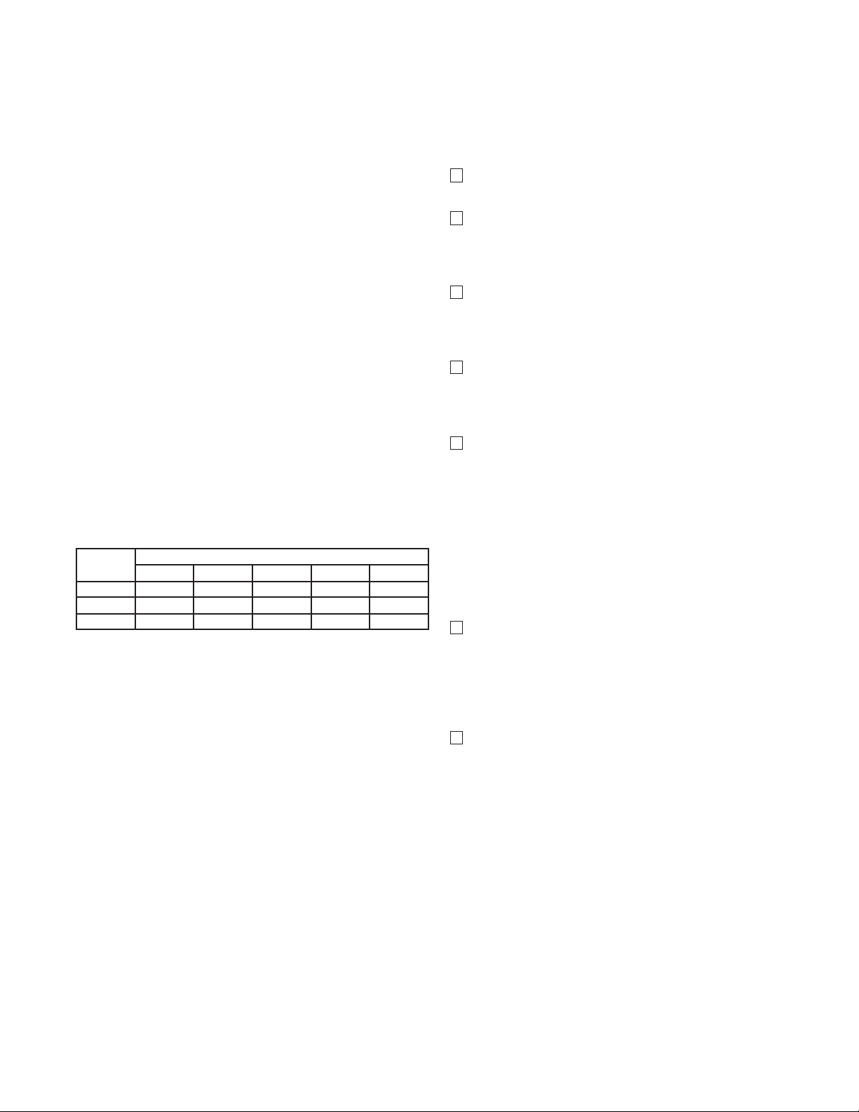
CBC 750 Maximum Current by Dip Switch
Installation
This installation and operations manual has been
arranged for the systematic installation and startup
of your Warner electric clutch-brake control system.
To achieve the best possible results, check off each
completed step in the space provided before proceeding to the next step.
Nominal
Voltage
6 0.910 2.350 3.183 3.760 4.340
24 0.227 0.641 0.881 0.940 1.175
90 0.060 0.176 0.256 0.282 0.310
1 2 3 4 5
Switch Setting
4. Start the top two (2) screws in the mounting
holes but do not tighten. Leave sufficient
space between the mounting surface and the
screw heads to mount the control.
5. Carefully slide the large slots of the top two
(2) mounting screw holes in the control
chassis over the heads of the mounting screws
already installed. Slide the control all the way
down on the screws.
Note: If the slots will not fit over the screw
heads, the two mounting screws must
be turned out (CCW) to increase
clearance before the control can be
mounted.
6. With the control chassis held firmly in place,
start the bottom two mounting screws into
their mounting holes. The ribbon connector
may have to be disconnected from the upper
terminal board to start the lower left hand
screw. Do not tighten the screws yet.
7. Line up the control squarely and tighten all
four mounting screws securely. Reconnect the
ribbon connector.
Note: If the control is mounted inside a control
enclosure and wires enter the control without
conduit, use plastic bushings to protect wires
entering the conduit entrance holes.
This completes the mounting installation of the
CBC-750 control chassis. Proceed to the wiring
section for control wiring information.
Warner Electric • 800-825-9050 819-0494
5
Page 6

CH
1
CH
2
A.C
Voltage
Input
Chassis
Gnd
2
3
4
5
6
7
1
TB6
Electrical Connections
System Wiring
5.69" (144.53)
14.01" (355.85)
13.00" (330.20)
11. 50" (292.10)
7.50"
(190.50)
9.56"
(242.82)
9.77"
(244.16)
4.78"
(121.41)
10.75"
(273.05)
3.09"
(78.49)
1.12" (28.45) DIA.
1.25" (31.75)
2.69"
(68.33)
.88" (22.35) DIA.
CONDUIT ENTRANCE (3)
3.16"
(80.26)
3.00"
(76.20)
.218" (5.54) DIA.
MTG. HOLES (4)
Wiring Precautions
Figure 1 - Outline Dimensions
These wiring precautions will help you properly
install and wire a trouble free control system.
However, they are intended as a guide only. Good
wiring practices as dictated by local codes should
always be followed when wiring the control system.
Contact with the electrical voltages
present in the CBC-750 series controls can cause
injury or death. To avoid these consequences, make
sure that all power is off.
1. Use proper gauge wire for Ac input Power,
clutch/brake wiring and DC switching circuits.
2. Do not run leads for the clutch/brake or
switching circuits in the same conduit or race
ways with other high voltage Ac or DC circuits
3. If wiring runs between the control and the
on the same machine.
clutch/brake or switching circuit are long, use
shielded cable with the shield grounded at the
control end to reduce noise pickup and
electrical interference.
4. Do not incorporate switching circuits in series
with clutch or brake outputs of the control as
this will cause damage to the control and will
void the warranty.
Warner Electric • 800-825-9050 819-0494
6
5. Do not run more than one magnet load from
each output channel as this may result in
erratic operation or damage to the control and
will void the warranty.
6. Use the control only as a clutch/brake power
source, not as a stand alone power supply.
Using the control other than in the manner
intended will void the warranty.
7. Do not switch between outputs to a single
clutch/brake as this may damage the control
and will void the warranty.
AC Input Power Wiring
Refer to Figure 2, below, for terminal strip wiring.
Figure 2 - C/B and Power Terminal Connection
Page 7

120
220
240
SW1
Figure 3 - AC Power Selector Switch
1. Connect a ground wire from terminal 7
or terminal board TB-6 to a good ground
point on the machine frame or in the control
panel. Tighten both connections.
2. Connect a wire from terminal 6 of TB-6
to the hot side of the AC input line power
buss. Tighten both connections.
2. Connect the brake magnet wires to
terminals 1(+) and 2(-) of TB-6. Wiring to the
brake field or magnet may be either by
screw terminals or lead wires depending on
the Warner Electric model. Tighten the control terminal connections and insure that the
brake magnet connections are properly
fastened and secured.
Note: If shielded wire is used for wiring the clutch
field or magnet and brake magnet, connect
the shield at the control end to Terminal 7 of
TB-6. Do not connect the shield at the magnet
end.
Insure that the shield lead at the
control end does not contact any of the other
terminal connections as shorting and control
damage may result.
3. Connect a wire from terminal 5 of TB-6
to the neutral side of the AC input power
buss. Tighten both connections.
4. Set the AC input power selector switch
SW-1 for the proper AC input level.
Refer to Figure 7, Page 10 for location of
switch SW1, which is also diagrammed
below.
Clutch-Brake Wiring
Refer to Figure 2 for terminal strip connections.
Note: Normally, the brake magnet should be
connected to Channel 1 output and the
clutch field or magnet connected to Channel 2
output for proper functioning of the various
input control circuits. Other connections are
possible.
1. Connect the clutch field or magnet wires to
terminals 3(+) and 4(-) of TB-6. Wiring to the
clutch field or magnet may be either by
screw terminal or lead wires depending on
the model of the Warner Electric clutch.
Tighten the control terminal connections
and insure that the clutch field or magnet
connections are securely fastened.
Switching Inputs
Warner Electric’s CBC-750 Series Controls have been
designed to provide the user with numerous switching and signal input configurations. figures 4a - 4f,
starting below, describe them. Terminal blocks TB-1,
TB-2 and TB-3 provide for input connection depending on the type of device being used for switching
input. Select the proper diagram depending on your
input and wire according to the steps listed.
Note: Only two of the three terminals designated
for each input function are used, regardless of
the input switching.
All inputs shown are connected to the Channel 2
Input. The other input connections are identical to
those of Channel 2 Input. The (X) designation noted
below refers to any one of terminals 1-7 of the
appropriate terminal strip, depending on the function being used. See Figure 7, Page 10 to determine
the terminals to be used, which depend on function
and setup.
Warner Electric • 800-825-9050 819-0494
7
Page 8

(COMMON)
TB-1
(10-30VDC/24VAC)
TB-2
(120VAC)
TB-3
1
1
1
120VAC, 50/60HZ
+
(COMMON)
TB-1
(10-30VDC/24VAC)
TB-2
(120VAC)
TB-3
1
1
1
120VAC, 50/60 HZ
(Common)
TB-1
(10-30VDC/240VAC)
TB-2
(120VAC)
TB-3
(10-30VDC)
_
+
1 1
1
1
1
(Common)
TB-1
(10-30VDC/24VAC)
TB-2
(120VAC)
TB-3
24VAC, 50/60 Hz
1
11
(Common)
TB-1
(10-30VDC/24VAC)
TB-2
(120VAC)
TB-3
(10-30VDC)
+
1
11
(Common)
TB-1
(10-30VDC/24VAC)
TB-2
(120VAC)
TB-3
10 to 30VDC or 24VAC
+
Figure 4a - NPN Transistor Connection
1. Connect neutral side of 24VAC to terminal (X)
of TB-1.
2. Connect output side of triac switch to terminal
(X) of TB-2.
Figure 4d - Switch or Relay Contact
Connections
1. Connect negative (-) or neutral side of
voltage source to terminal (X) of TB-1.
2. Connect output side of relay or switch to
terminal (X) of TB-2.
1. Negative (-) side of supply connected to
2. Connect output side of triac switch to
Figure 4c - Triac Connection for AC Input (24V)
1. Connect neutral side of 24VAC to terminal (X)
2. Connect output side of triac switch to
Figure 4b - PNP Transistor Connection
terminal (X) of TB-1
terminal (X) of TB-2.
of TB-1.
terminal (X) of TB-2.
Figure 4 - Typical Input Connections. Note that terminal strip TB-3 is not used.
Figure 4e - Switch or Relay Contact
1. Connect neutral side of 120 VAC source to
terminal (X) of TB-1.
2. Connect output side of relay or switch to
terminal.l (X) of TB-3.
Connections (120 VAC)
Figure 4f - Triac Connection for AC Input (120
V)
1. Connect neutral side of 120 VAC source to
terminal (X) of TB-1.
2. Connect output side of relay or switch to terminal (X) of TB-3.
Warner Electric • 800-825-9050 819-0494
8
Page 9

Auxiliary Outputs
TB-4
CHANNEL 1
CHANNEL 2
OUTPUT INHIBIT
CHANNEL 2 OVERRIDE
FIGURE 4
(+)
+
+
+
+
(-)
24VDC MAXIMUM
-
-
-
-
1
2
3
4
5
6
7
8
-.
C
TB -5
12VDC +
250 ma. MAX -.
CH1
REMOTE TORQUE
ADJUSTMENT
CH2
REMOTE TORQUE
ADJUSTMENT
1
2
3
4
5
6
7
8
Auxiliary indicator outputs are provided for optional
indicators to monitor the status of Channel 1,
Channel 2, output inhibit, and Channel 2 override.
These are opto-isolated NPN outputs.
Refer to Figure 5, below, for connections.
Figure 5 - Auxiliary Indicator Connections
Note: All resistors and LED’s shown are furnished
by the user. The power source may be either
external user furnished or the CBC-750’s
12VDC auxiliary power supply.
Remote torque Adjust
Potentiometers
Optional remote torque adjust inputs are provided
for torque adjust potentiometer connection.
Refer to Figure 6, below, for connections.
Note: The remote potentiometer should be wired
using shielded cable to prevent noise pick
up. The shield should be connected only
to chassis ground at terminal 7 of TB-6.
Your CBC-750 control has now been completely
wired. Before proceeding to the set-up and start-up
sections of this manual, double check to insure that
the control is properly wired.
Do not use incandescent lamps
because their high inrush current may destroy the
opto-coupler on the CBC-750.
Figure 6 - Remote Potentiometer Connection
Warner Electric • 800-825-9050 819-0494
9
Page 10
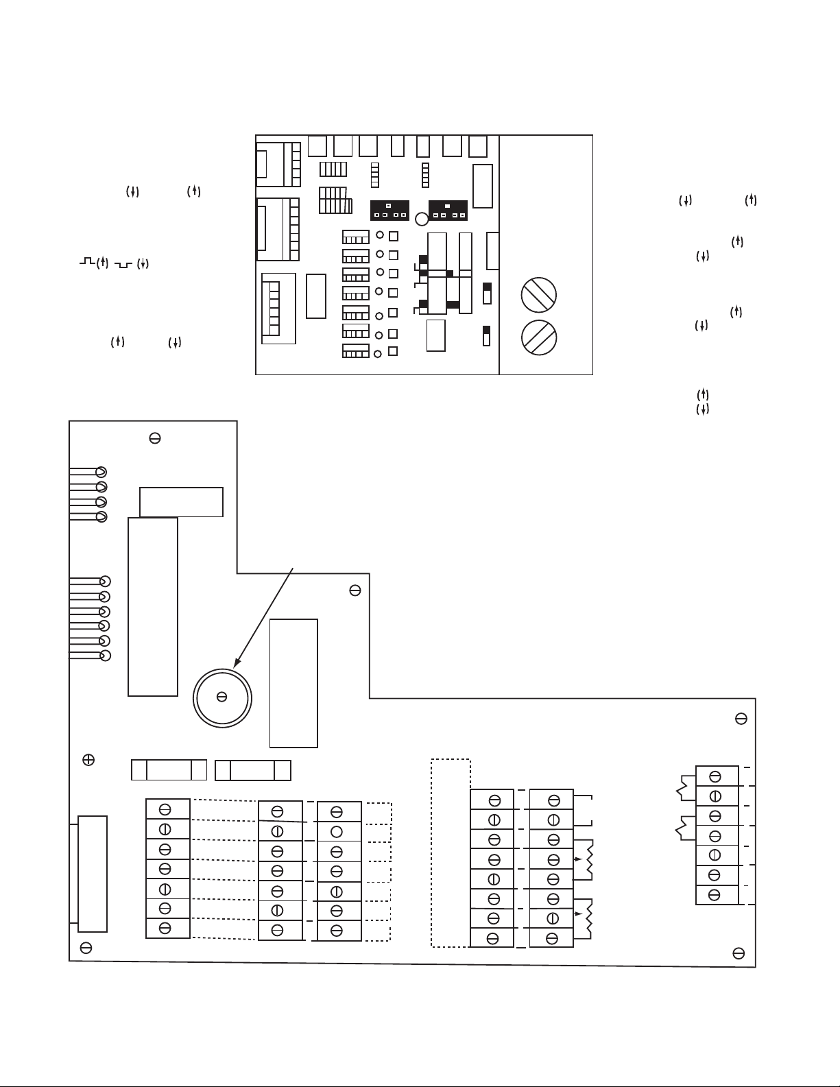
SW8
Channel 2 current
range selector
SW7
Channel 1 current
range selector
SW8 SW7
SW6
SW10
SW3
SW11
SW2
SW4
SW5
J1-4
J1-3
J1-2
J1-1
J2-8
J2-7
J2-6
J2-5
J2-4
J2-3
C47
TB8
YEL
YEL
RED
RED
BLUE
BLUE
120
220
240
SW1
TB7
AC Voltage Selection
WHT
BLK
BLK/WHT
BLK/RED
P1
P2
J3
TB1
TB2
TB3
TB4
TB5
1
1
2
2
3
3
4
4
5
5
6
6
7
7
COM
COM
COM
COM
COM
COM
COM
CH 2
Input
CH 1
Input
Inhibit
CH 2
Input
Inhibit
AUX
Input
CH 1
Input
Output
Inhibit
CH 2
Override
(10-30)
VDC
(10-30)
VDC
(10-30)
VDC
(10-30)
VDC
(10-30)
VDC
(10-30)
VDC
(10-30)
VDC
(120 VAC )
CH 2
Input
CH 1
Input
Inhibit
CH 2
Input
Inhibit
AUX
Input
CH 1
Input
Output
Inhibit
CH 2
Override
Optional
AUX
Indicator
Outputs
+
+
+
+
_
_
_
_
CH 1
CH 2
Output
Inhibit
CH 2
Override
+
_
12VDC
250 mA
Optional
Remote
Torque
CH
CH
1
2
Optional
Remote
Torque
SW6
Channel 2 OEX
Enable /disable
SW10
Channel 1
input invert
SW3
Level/pulse selector
level , pulse
SW11
Auxiliary input selector
Channel 1
Channel 2
SW5
Channel 1 OEX
enable / disable
SW2
Channel 1 local
or remote
torque adjust
SW4
Channel 2 local
or remote
torque adjust
7
6
1
2
3
4
5
TB6
CH
1
CH
2
A.C.
Voltage
Input
Chassis
GND
Figure 8 - Main Board Switches - Black
Switches
Warner Electric • 800-825-9050 819-0494
10
Figure 7 - Terminal board Overview - Inside
Page 11

System Start-Up
Do not apply power to the control
at this time.
1. Double check all control and magnet
wiring connections to insure that they are
exactly in accordance with the appropriate
wiring diagrams.
6 Volt Table
Models Range #
EC 650, 1000 4
SF 650, 1000
AT 55
SF 500, 825 Brg, 1000, 1525 5
EC 825, 1225
AT 115
2. Turn the Channel 1 and Channel 2 torque
adjust potentiometers fully counterclockwise, their minimum output settings.
3. For future reference, record the model
numbers and voltages of the clutch/brake
magnets and /or fields in the blank spaces
below:
Channel 1___________ Voltage___________
Channel 2___________ Voltage___________
4. Refer to dip switch selection charts below
and Figure 8, facing page. Set dip switches
SW7 and SW8 for the proper range settings
based on magnet and field sizes. Switch SW7
sets the current ranges for Channel 1 and
switch SW8 sets the range for
Channel 2.
CBC-750
Current Range Selections
For Dip Switches SW7 and SW8
6 Volt Table
Models Range #
SF/PB 120, 170, 250, 400 1
EC/EB 375, 475 2
EM 50, 180
PB/PC 500, 1225, 1525 3
EB 1225
EM 210
AT 25
PB/PC 825, 1000 4
PB 650
EC/EB 650, 825, 1000
24 Volt Table
Models Range #
SF/PB 120, 170, 250, 400 1
EC/EB 375, 475 2
EM 4, 5 2
PC/PB 500, 825, 1225 3
SF 825
EC/EB 825
EB 1225
AT 25
PC/PB 1000, 1525 4
PB 650
EC/EB 650, 1000
SF 650, 1225
EM 6
AT 55
SF 500, 1000, 1225, 1525 5
90 Volt Table
Models Range #
SF/PB 120, 170, 250, 400 1
EC/EB 375, 475 2
EM 50 , 180
PC/PB 1225, 1525 3
PB 650
SF 825, 1225
EB 650, 1225
EM 210
AT25
Warner Electric • 800-825-9050 819-0494
11
Page 12

90 Volt Table (Cont'd)
Channel
Input
(See Note 1)
Channel 1 Input
Inhibit
Channel 2
Input
Channel 2 Input
Inhibit
Auxiliary
Input
(See Note 2)
Output Inhibit
Input
Channel 2 Override
Input
Channel 1
Output
Channel 2
Output
Off
Off
On
On
2 Inputs/Channel 1 & 2
Full On
Not Adj.
On
Adj.
C
Channel 2
Input
Channel 2
Input Inhibit
Auxiliary
Input
(See Note)
Output Inhibit
Input
Channel 2
Override
Input
Channel 1
Output
Channel 2
Output
Models Range #
PC/PB500, 1000 4
EC/EB 1000
SF 1525
AT 55
PB/PC 825 5
EC 650, 1225
EC/EB 825
SF 500, 650, 825 Brg, 1000
AT 115, 205
5. Refer to Figure 8, Page 10. Set the input voltage selector switch SW1 for the AC input
being used.
6. Refer to Figure 8, Page 10. Set switches
SW2 and SW4 in accordance with either of
the following:
• If local torque adjust potentiometers are
used, set to “up” position.
Notes:
1. Channel 1 input signal can be configured by
SW10 to provide same function with inverted
signal.
2. Auxiliary input shown configured as a Channel 1
input, can be configured by SW11 to provide
same operation as a Channel 2 input.
3. Diagram reflects current flow through opticallyisolated control inputs in either sourcing or
sinking made.
4. See set-up switches on back cover.
• If external or remote torque adjust potentiometers are wired to the control, set to
“down” position. Refer to Figure 9 below.
Input/Output signal Relationships, when
makingthe settings required in steps 7 -
10. Circuit logic is diagrammed here for
your convenience.
7. Proper operating mode setting (switch SW3)
depends on how the control inputs are wired:
• Set SW3 in the “up” position for level
input operation from a single switching
device. Channel 2 input controls output
switching when the control is operated in
this mode.
• Set switch SW3 in the “down” position for
pulse input mode operation. This requires
input switching on both Channel 1 and
Channel 2 inputs.
Notes:
1. Auxiliary input shown configures as a Channel 2
input. Auxiliary input non-functional if configured
as a Channel 1 input when control is configured
for a singal input from Channel 2.
2. Diagram reflects current flow through opticallyisolated control inputs in either sourcing or
sinking mode.
3. See set-up switches on back cover.
8. Overexcitation Set-up
Switch SW5 controls the overexcitation pulse
to Channel 1 while switch SW6 controls the
overexcitation to Channel 2. to enable the
OEX, set the switch in the “down” position for
the channel to be overexcited. The “up”
positions disable the OEX pulses.
Warner Electric • 800-825-9050 819-0494
12
Figure 9 - Input/Output Relationships
Page 13

9. Channel 1 input invert switch SW10 selects the
Channel 1 input for normal or inverted signals.
Set the switch for the desired response when
the control is operated in the pulse mode:
• “Down” position applies voltage for control
response.
• “Up” position removes voltage from control
response.
16. Observe that the Channel 1 output should also
be off. Slowly rotate the Channel 2 torque
adjustment potentiometer CW noting that its
LED illuminates and increases in intensity as
the maximum setting is approached.
17. If input inhibit functions are used, activate the
inputs. Check to insure that input inhibit LED’s
illuminate, and that switching inputs do not
affect the output state.
10. If an auxiliary input sensor such as a photoelectric scanner is used, auxiliary input switch
SW11 must be set for either Channel 1 or
Channel 2 input:
• “Up” position inputs to Channel 1
switching.
• “Down” position inputs to Channel 2
switching.
11. Double check all switch settings to insure they
are in the proper position for the desired
functions.
12. Apply power to the CBC-750 control. The
machine must not be running during
preliminary tests.
13. Observe the front panel indicator LED’s as
follows:
• With the torque adjust potentiometers set
at minimum, the output indicators should
be “off”.
18. if any of the auxiliary inputs are used, check
that indicator LED’s illuminate and control
response is proper.
19. Set the system to cycle automatically between
Channel 1 and Channel 2 outputs. Observe the
front panel indicators for proper functioning
based on actual inputs and outputs. Check that
short circuit indicators do not illuminate.
20. Start the machine and observe the control and
the machine for proper operation.
21. Set the Channel 1 and Channel 2 torque adjust
potentiometers to the desired level.
Setting the torque adjustments too
low will cause excessive clutch and brake slip
leading to excessive magnet and/or rotor wear.
22. Shut down the machine and turn off the control.
23. Latch the top board assembly to the chassis by
pushing down on the plastic locking pins.
• Check to insure that Channel 1 and
Channel 2 short circuit indicator LED’s are
not illuminated.
• If short circuit lights illuminate, press reset
button on front panel to clear the short
light(s). If short LED’s illuminate again,
immediately shut off AC power and follow
the instructions in the troubleshooting
section of this manual on page 14 to
located the short circuit.
14. Slowly rotate the Channel 1 torque adjust
potentiometer CW to maximum output, noting
that the Channel 1 output LED illuminates and
24. Install the cover (if used) on the chassis by
sliding the two clips upward, latching the
cover in place.
This completes the installation and start-up of the
CBC-750 control system. If problems are encountered during start-up and check-out, refer to the
troubleshooting section of this manual.
if any problems can not be resolved by following
troubleshooting procedures, and the control is
properly installed and wired, contact your local
Warner Electric Market Representative or our
Applications Engineering Group at (815) 389-3771
for further assistance.
gradually brightens.
15. Activate the switching device to switch from
Channel 1 to Channel 2 output.
Warner Electric • 800-825-9050 819-0494
13
Page 14

General
The chart below will be helpful in solving problems which may be encountered in both start-up and normal
operation. If situations are encountered which are beyond the scope of this troubleshooting guide, please
contact your local Warner Electric Market Representative or ask for applications assistance by phoning (815)
389-3771 and asking for the Application Engineering department.
Symptom A: Indicator LED’s do not illuminate when power is applied.
Probable Cause Solution
No power applied to control Check that AC power to control is on.
Check for proper AC power at terminals 5 and 6 of TB-6
Input line fuse is blown Check for blown power fuse F1. Replace if blown.
Interboard connectors are loose Check that cables and connectors are securely fastened
to main control board.
torque adjust pots set at minimum Turn torque adjust potentiometer CW to increase torque level.
No internal power Check for AC input. Check for 12VDC at terminals 1 and 2 of
TB-5 and across channel 1 and channel 2 outputs. If no
voltage present, replace main board.
Symptom B: Short circuit LED’s illuminate
Probable Cause Solution
I
mproper magnet or field Coil voltage Check magnets and fields for proper coil voltage ratings.
Replace if wrong voltage.
Shorted magnet or field coil Check resistance of magnet coils. Replace magnet or field if
shorted.
Wiring between control and magnets or Check for shorted conditions in wiring between controls
fields shorting and magnets or fields. Replace if defective.
Transient noise Check for source of transient noise and suppress. Wire
control using shielded cables. Segregate wiring runs.
Symptom C: Magnets or fields do not engage when power is applied
Probable Cause Solution
Torque adjust set at zero (0) Increase torque setting.
Current range switches improperly set check dip switch settings per charts found on page 12
and reset if required.
No power applied to control Refer to symptom A above.
Output inhibit input activated Check input status on output inhibit input.
System incorrectly wired Check wiring per the wiring diagram and rewire if
necessary.
Warner Electric • 800-825-9050 819-0494
14
Page 15

Symptom D: Magnet or field on channel 1 does not disengage when input is switched
Probable Cause Solution
Channel 2 override input activated Check status of channel 2 override, and release if
activated.
Faulty control Replace main control logic board.
Symptom E: Magnets or fields do not appear to have enough torque
Probable Cause Solution
Dip switches improperly set Check dip switch settings per chart found on page 9 and
reset if necessary.
Magnets or fields incorrectly wired Check wiring between control and magnets or fields.
Require if necessary.
Torque adjust potentiometers set too low Check setting of torque adjust potentiometers and
increase if required.
Clutches or brakes incorrectly sized Verify proper size by repeating sizing process in Warner
Electric Master Catalog, form P-137.
Symptom F: Outputs don’t switch; inputs don’t switch
Probable Cause Solution
Input incorrectly wired Check for proper wiring schemes and Require if necessary.
Faulty switching device Check for proper operation and replace if defective.
Control switches on main board not set Check positions of switches on main board and reset for
properly proper configuration.
Faulty control Replace main control logic board.
Replacement Parts
CBC-750-6 Complete Control Less Cover 6041-448-001
Main Control Logic Board Assembly 6041-101-001
Cover 6041-101-001
Fuse F1 458-8001-074
Fuse F2 458-8001-010
CBC-750-24 Complete Control Less Cover 6041-448-002
Main Control Logic Board Assembly 6041-101-002
Cover 6041-101-004
Fuse F1 458-8001-074
Fuse F2 458-8001-028
CBC-750-90 Complete Control Less Cover 6041-448-003
Main control Logic Board Assembly 6041-101-003
Cover 6041-101-004
Fuse F1 458-8001-074
Fuse F2 458-8001-026
Warner Electric • 800-825-9050 819-0494
15
Page 16

Warranty
Warner Electric LLC warrants that it will repair or replace (whichever it deems advisable) any
product manufactured and sold by it which proves to be defective in material or workmanship within a period of one (1) year from the date of original purchase for consumer,
commercial or industrial use.
This warranty extends only to the original purchaser and is not transferable or assignable
without Warner Electric LLC’s prior consent.
Warranty service can be obtained in the U.S.A. by returning any defective product,
transportation charges prepaid, to the appropriate Warner Electric LLC factory. Additional
warranty information may be obtained by writing the Customer Satisfaction Department,
Warner Electric LLC, 449 Gardner Street, South Beloit, Illinois 61080, or by calling
815-389-3771.
A purchase receipt or other proof of original purchase will be required before warranty service
is rendered. If found defective under the terms of this warranty, repair or replacement will be
made, without charge, together with a refund for transportation costs. If found not to be
defective, you will be notified and, with your consent, the item will be repaired or replaced
and returned to you at your expense.
This warranty covers normal use and does not cover damage or defect which results from
alteration, accident, neglect, or improper installation, operation, or maintenance.
Some states do not allow limitation on how long an implied warranty lasts, so the above
limitation may not apply to you.
Warner Electric LLC’s obligation under this warranty is limited to the repair or replacement of
the defective product and in no event shall Warner Electric LLC be liable for consequential,
indirect, or incidental damages of any kind incurred by reason of the manufacture, sale or
use of any defective product. Warner Electric LLC neither assumes nor authorizes any other
person to give any other warranty or to assume any other obligation or liability on its behalf.
WITH RESPECT TO CONSUMER USE OF THE PRODUCT, ANY IMPLIED WARRANTIES WHICH
THE CONSUMER MAY HAVE ARE LIMITED IN DURATION TO ONE YEAR FROM THE DATE OF
ORIGINAL CONSUMER PURCHASE. WITH RESPECT TO COMMERCIAL AND INDUSTRIAL
USES OF THE PRODUCT, THE FOREGOING WARRANTY IS IN LIEU OF AND EXCLUDES ALL
OTHER WARRANTIES, WHETHER EXPRESSED OR IMPLIED BY OPERATION OF LAW OR
OTHERWISE, INCLUDING, BUT NOT LIMITED TO, ANY IMPLIED WARRANTIES OF
MERCHANTABILITY OR FITNESS.
Some states do not allow the exclusion or limitation of incidental or consequential damages,
so the above limitation or exclusion may not apply to you. This warranty gives you specific
legal rights and you may also have other rights which vary from state to state.
Changes in Dimensions and Specifications
All dimensions and specifications shown in Warner Electric catalogs are subject to change
without notice. Weights do not include weight of boxing for shipment. Certified prints will be
furnished without charge on request to Warner Electric.
Warner Electric LLC
31 Industrial Park Road • New Hartford, CT 06057
815-389-3771
www.warnerelectric.com
P-270 819-0494 6/12 Printed in USA
• Fax: 815-389-2582
 Loading...