

Page 1
WINCH USER GUIDE
WARN® 3000ACI Utility Winch
Part Number: 93000
English ..................................................1
Spanish .............................................. 17
French ................................................ 33
German............................................... 49
Italian ................................................ 65
Dutch ................................................. 81
Finnish ............................................... 97
Swedish ........................................... 113
Portuguese ...................................... 129
PAGE 1 85366 Rev. A0
Page 2
Your safety, and the safety of others, is very important. To help you make informed decisions about safety, we have provided
installation and operating instructions and other information on labels and in this guide. This information alerts you to potential hazards
that could hurt you or others. It is not possible to warn you about all potential hazards associated with this product, you must use your
own good judgment.
CARELESS WINCH INSTALLATION AND OPERATION CAN RESULT IN SERIOUS INJURY OR EQUIPMENT DAMAGE. READ
AND UNDERSTAND ALL SAFETY PRECAUTIONS AND OPERATING INSTRUCTIONS BEFORE INSTALLING AND OPERATING
THIS PRODUCT.
This guide identifies potential hazards and has important safety messages that help you and others avoid personal injury or death.
WARNING and CAUTION are signal words that identify the level of hazard. These signal words mean:
WARNING signals a hazard that
CAUTION signals a hazard that
This guide uses
special attention
NOTICE
to call attention to important mechanical information, and Note: to emphasize general information worthy of
could
cause serious injury or death, if you do not follow recommendations.
may
cause minor to moderate injury, if you do not follow recommendations.
Product Description: WARN® 3000ACI Utility Winch
The WARN® 3000ACI Utility Winch is a powerful pulling tool. Powered by a 115 or 230 volt AC power source
this compact winch has a pulling capacity of 3000 pound / 1361 kilos.
The units has a station types control switch for power in and power out operation, 100‖ of 5/16‖ wire rope
and clasp hook. A freespooliong clutch is a standard option.
Introduction
Thank you for choosing WARN® for your utility winch needs. All WARN® products have been designed and
manufactured for many years of problem-free operation. For future reference please record the following
information:
Model/Part Number: Date of Purchase:
Before you begin
Read the instructions completely to familiarize yourself with the installation process.
Review all the notices, cautions and warnings to make sure the kit will be installed correctly and safely.
PAGE 2 85366 Rev. A0
Page 3
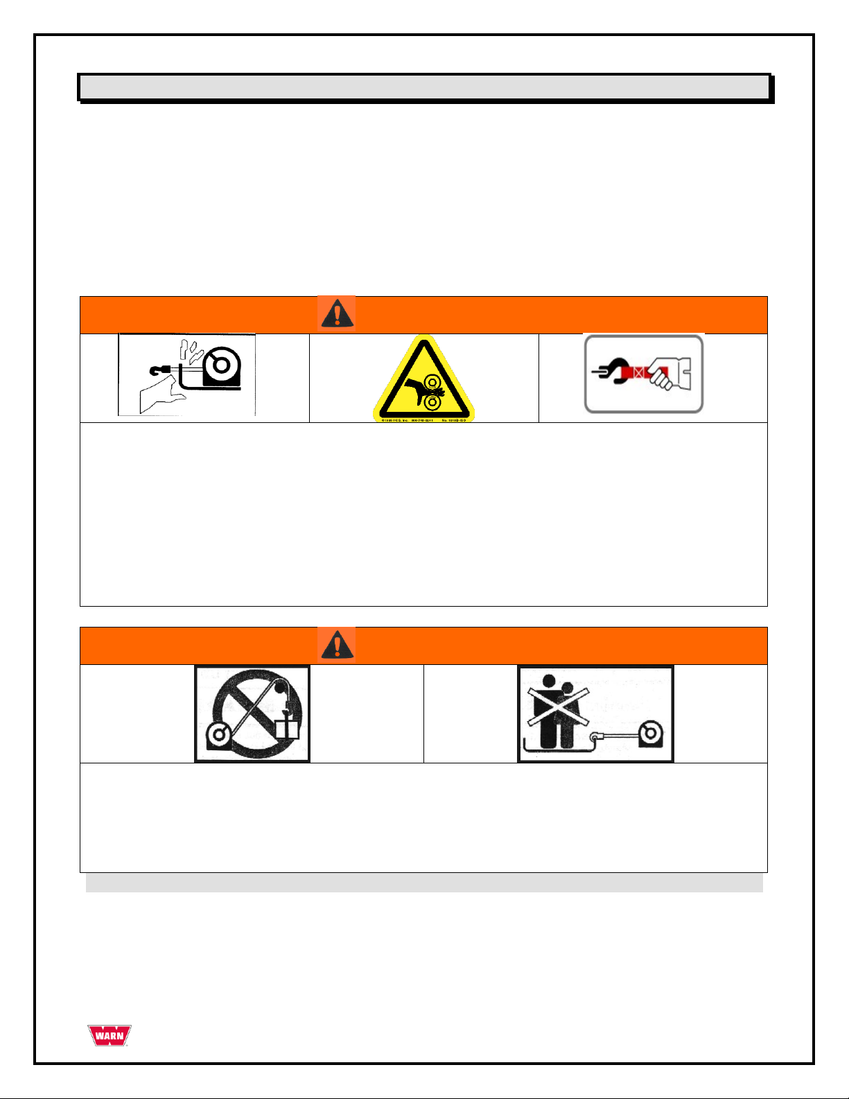
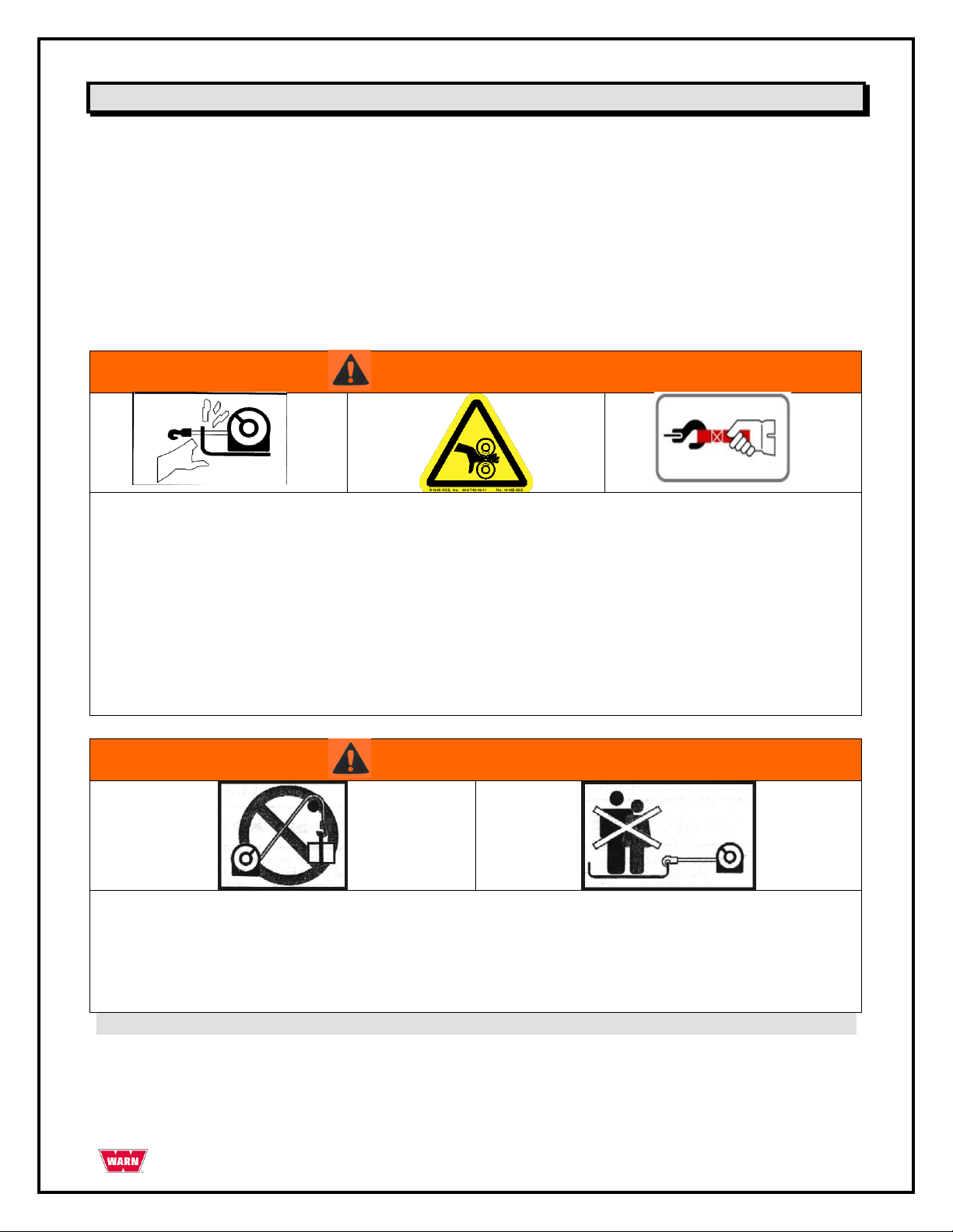
WARNING
MOVING PARTS ENTANGLEMENT HAZARD
Failure to observe these instructions could lead to severe injury or death.
To avoid injury to hands or fingers.
• Always keep hands clear of wire rope, hook loop, hook and fairlead opening during installation, operation and when
spooling in or out.
• Always use extreme caution when handling hook and wire rope during spooling operations.
• Always use supplied hook strap whenever spooling wire rope in or out, during installation or operation to avoid injury
to hands or fingers.
WARNING
FALLING OR CRUSHING HAZARD
Failure to observe these instructions could lead to severe injury or death.
• Never use as an overhead hoist, or to suspend a load.
• Never use to lift or move persons.
Safety Precautions
The following are general safety precautions that every winch operator should know. Taking precedence over
any specific rule listed here, however, is the most important rule of all—USE COMMON SENSE.
A few minutes spent reading these rules can make an operator aware of dangerous practices to avoid and
precautions to take for his own safety and the safety of others. Frequent examinations and periodic
inspections of the equipment as well as conscientious observance of safety rules may save lives as well as
time and money.
PAGE 3 85366 Rev. A0
Page 4

Safety Precautions - continued
CAUTION
MOVING PARTS ENTANGLEMENT HAZARD
Failure to observe these instructions could lead to minor to moderate injury.
General Safety:
• Always Know Your Winch: Take time to fully read and understand the included Installation and Operations guide,
and Basic Guide to Winching Techniques, in order to understand your winch and the winching operation.
• Never operate this winch if you are under 16 years of age.
• Never operate this winch when under the influence of drugs, alcohol or medication.
• Never exceed winch or wire rope rated capacity. Double line using a snatch block to reduce winch load.
Installation Safety:
• Always choose a mounting location that is sufficiently strong to withstand the maximum pulling capacity of your
winch.
• Always use factory approved switches, remote controls, accessories and installation components.
• Always use grade 5 or better hardware, never weld bolts and never use longer bolts than those supplied from
factory.
• Always complete winch mounting and attachment of hook to hook loop before wiring winch during installation.
• Always position fairlead with WARNING label on top.
• Always spool the wire rope onto the drum as indicated by the drum rotation label on the winch.
Required for automatic brake to work (if winch is so equipped) and for correct installation orientation.
• Always prestretch wire rope and respool under load before use. Tightly wound wire rope reduces chances of
"binding", which is wire rope working it's way down into a loosely wound wire rope layer, and catching or damaging
itself.
Winching Safety:
• Always inspect winch installation and wire rope and hook condition before operating winch. Frayed, kinked or
damaged wire rope must be replaced immediately. Loose or damaged winch installation must be corrected
immediately.
• Never hook wire rope back onto itself. This damages the wire rope. Always use a choker chain, wire choker rope or
tree trunk protector on the anchor.
• Always prior to winching, remove any element that may interfere with safe winch operation.
• Always take your time when rigging for a winch pull.
• Always be certain the anchor you select will withstand the load, and the strap or chain will not slip.
• Never engage or disengage clutch if winch is under load, wire rope is in tension or wire rope drum is moving
• Always unspool as much wire rope as possible when rigging. Double line or pick distant anchor point.
• Never winch with less than 5 wraps of wire rope around the drum, the wire rope could come loose from the drum.
• Always stand clear of wire rope and load during operation.
• Never touch wire rope or hook while in tension or under load.
• Never touch wire rope or hook while someone else is at the control switch or during winching operation.
• Never touch wire rope or hook while remote control is plugged into winch.
• Always stand clear of wire rope and load and keep others away while winching.
• Always require operator and bystanders to be aware of stability during winching of vehicle and/or load.
• Always keep remote control lead clear of the drum, wire rope and rigging. Inspect for cracks, pinches, frayed wires
or loose connections. Replace if damaged.
PAGE 4 85366 Rev. A0
Page 5
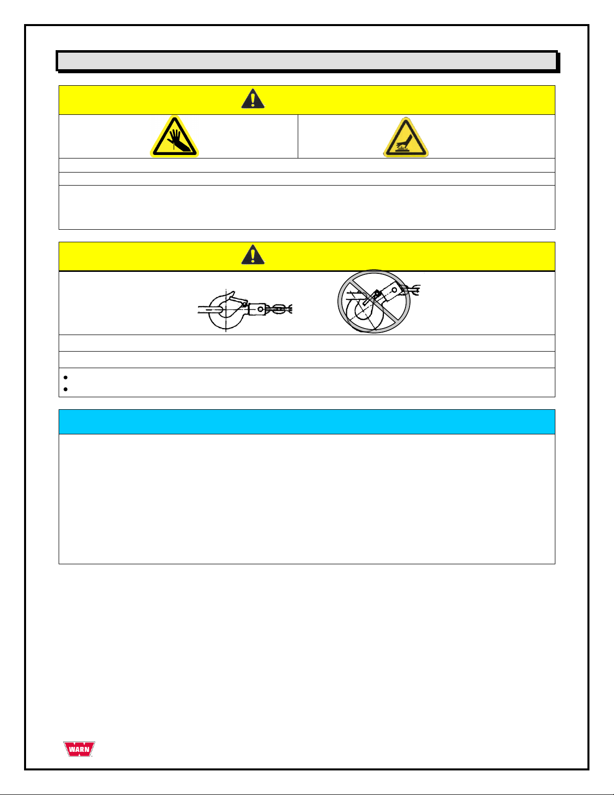
CAUTION
CUT AND BURN HAZARD
Failure to observe these instructions could lead to minor to moderate injury.
To avoid injury to hands and fingers:
• Always wear heavy leather gloves when handling a wire rope.
• Never let wire rope slip through your hands.
• Always be aware of possible hot surface at winch motor, drum or wire rope during or after winch use.
CAUTION
Moving Parts Entanglement Hazard
Failure to observe these instructions could lead to minor to moderate injury.
Never apply load to hook tip or latch. Apply load only to the center of hook.
Never use a hook whose throat opening has increased, or whose tip is bent or twisted.
NOTICE
AVOID WINCH AND EQUIPMENT DAMAGE
• Always avoid continuous side pulls, which can pile up wire rope at one end of the drum. This can damage your wire
rope or winch.
• Always ensure the clutch is fully engaged or Disengaged.
• Never use winch to tow other vehicles. Shock loads can momentarily exceed capacity of wire rope & winch
• Always use care to not damage your frame when anchoring your vehicle during a winching operation.
• Never "jog" wire rope under load. Shock loads can momentarily exceed capacity of wire rope and winch.
• Never use winch to secure a load during transport.
• Never submerge winch in water.
• Always store the winch in a protected, clean, dry area.
Safety Precautions - continued
PAGE 5 85366 Rev. A0
Page 6
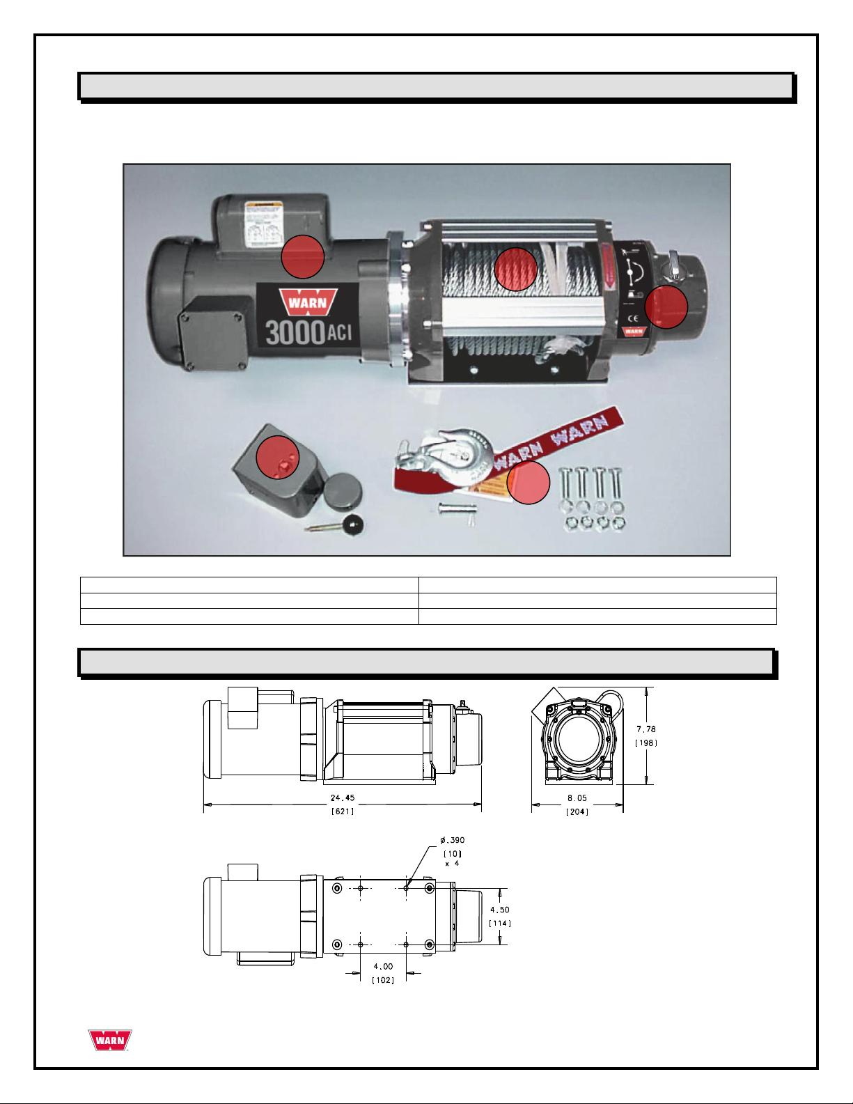
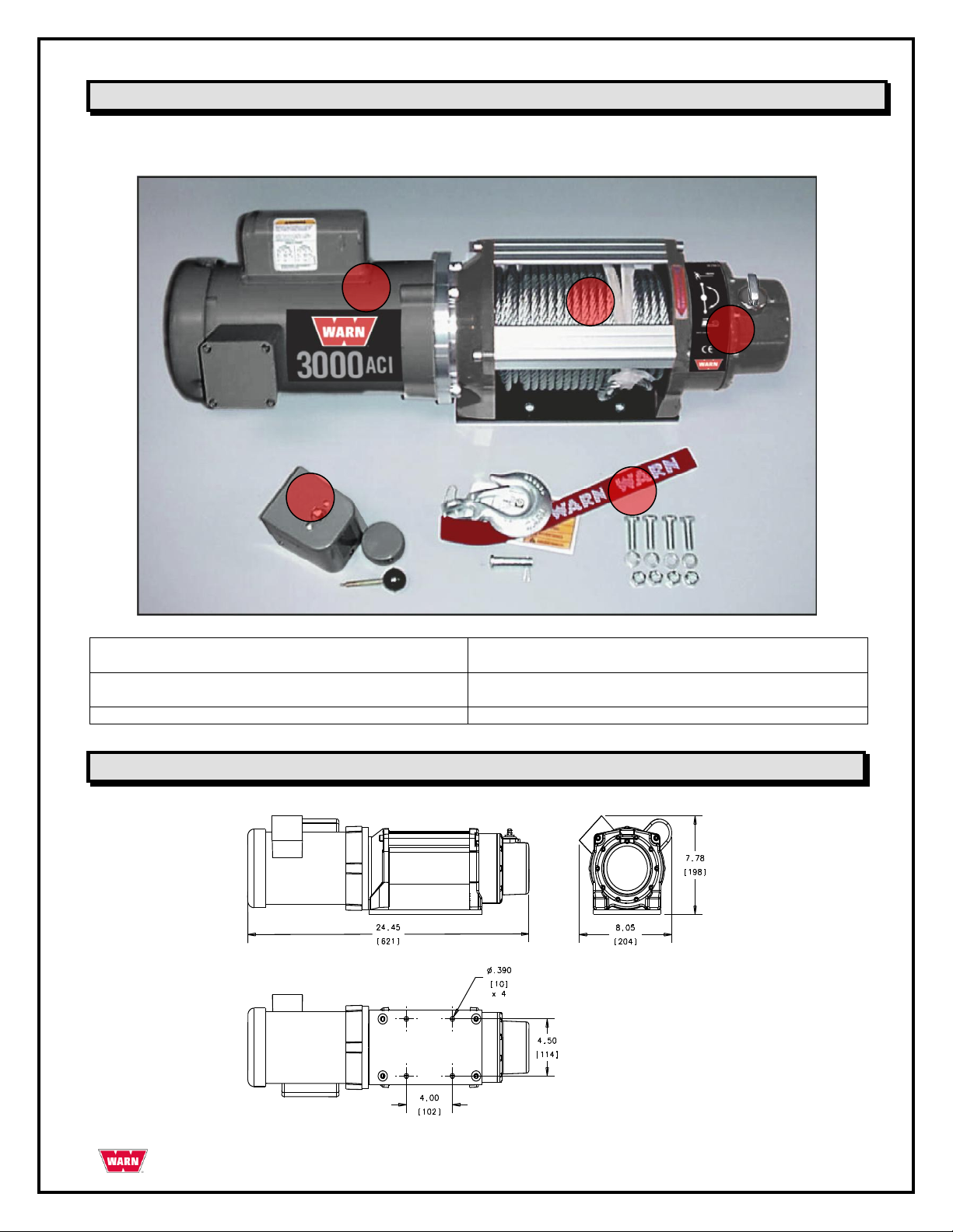
1. Powerfull .75 hp TEFC Induction Motor
2. Large Drum with 100‖ of 5/16 Cable
3. 3-Stage Planetary Geartrain with clutch
4. Station type control switch
5. Hardware Pack With Clasp Hook
1 2 3 4 5
Parts List
The WARN® 3000ACI Utility Winch consists of the following main components.
Dimensional Data for the WARN 3000ACI
PAGE 6 85366 Rev. A0
Page 7

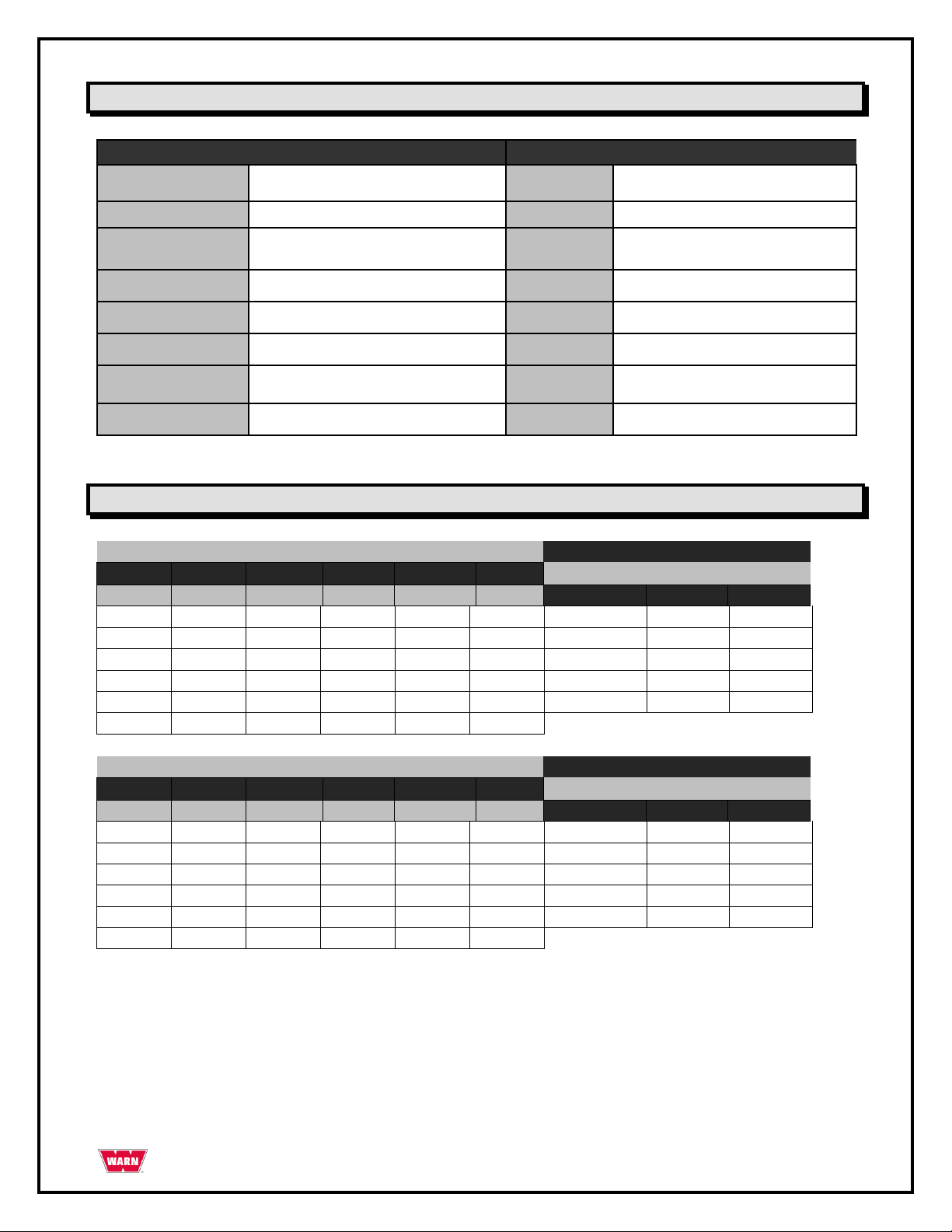
Specification Data for the WARN 3000ACI
Features
Pulling Capacity
3000lbs. (1361 kg)
Brake
Dynamic and Mechanical braking
Switch Type
GE Drum Switch CR102A1 Station Type
Warranty
1 year limited
Motor
TEFC Induction AC Motor
Wire Rope
5/16" X 100' (18.3 m)
HP
.75 HP 56C
Drum Diameter
2.5" (6.35 cm)
Power
120V 60 Hz or 230V 50Hz Single Phase AC
Fairlead
None
Gear Train
3-Stage planetary
Hole Pattern
4 holes
Gear Ratio
216:1
Electrical Leads
None
Clutch
Lever actuated sliding ring gear
Weight
76 lbs. (34.5 kg.)
PERFORMANCE DATA: 3000ACI
115V 60Hz Single Phase
Load
Current
Speed
Pulling Power by Wire Rope Layer
Lbs.
Kg
Amps
KW
Ft/min
M/min
Layer
lbs.
kg
0 0 9.1
1049
12.2
3.7
1
3000
1361
1000
453.6
11.0
1265
8.8
2.7
2
2700
1225
1500
680.4
12.7
1461
8.8
2.7
3
2460
1116
2000
907.2
14.8
1702
8.6
2.6
4
2250
1021
2500
1134
17.7
2036
8.5
2.6
5
2070
939
3000
1360.8
20.9
2300
8.1
2.5
PERFORMANCE DATA: 3000ACI
230V 50Hz Single Phase
Load
Current
Speed
Pulling Power by Wire Rope Layer
Lbs.
Kg
Amps
KW
Ft/min
M/min
Layer
lbs.
kg
0 0 4.6
1058
12.2
3.7
1
3000
1361
1000
453.6
5.5
1265
8.8
2.7
2
2700
1225
1500
680.4
6.4
1472
8.8
2.7
3
2460
1116
2000
907.2
7.4
1702
8.6
2.6
4
2250
1021
2500
1134
8.9
2047
8.5
2.6
5
2070
939
3000
1360.8
10.5
2415
8.1
2.5
Performance Data for the WARN 3000ACI
PAGE 7 85366 Rev. A0
Page 8
CAUTION
Winch Failure Hazard
Failure to observe these instructions could lead to minor or moderate injury.
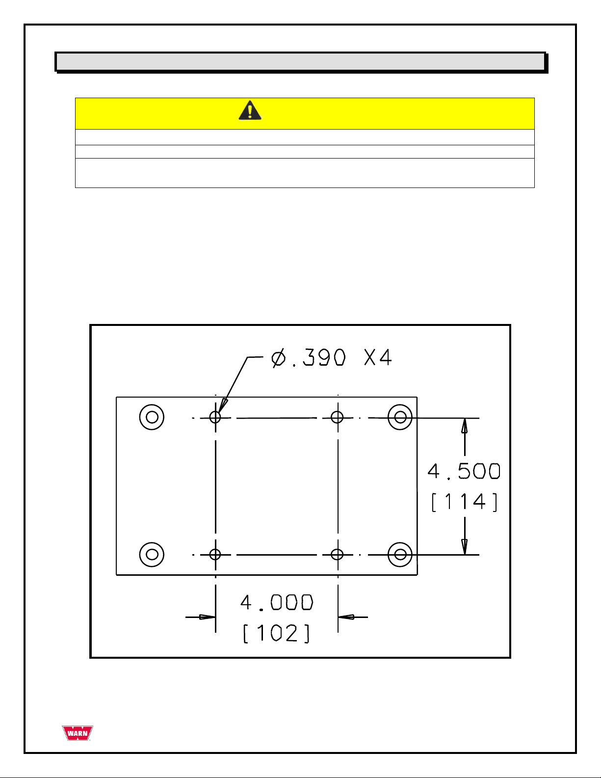
Always choose a mounting location that is sufficiently strong to withstand the loads you
intend to winch
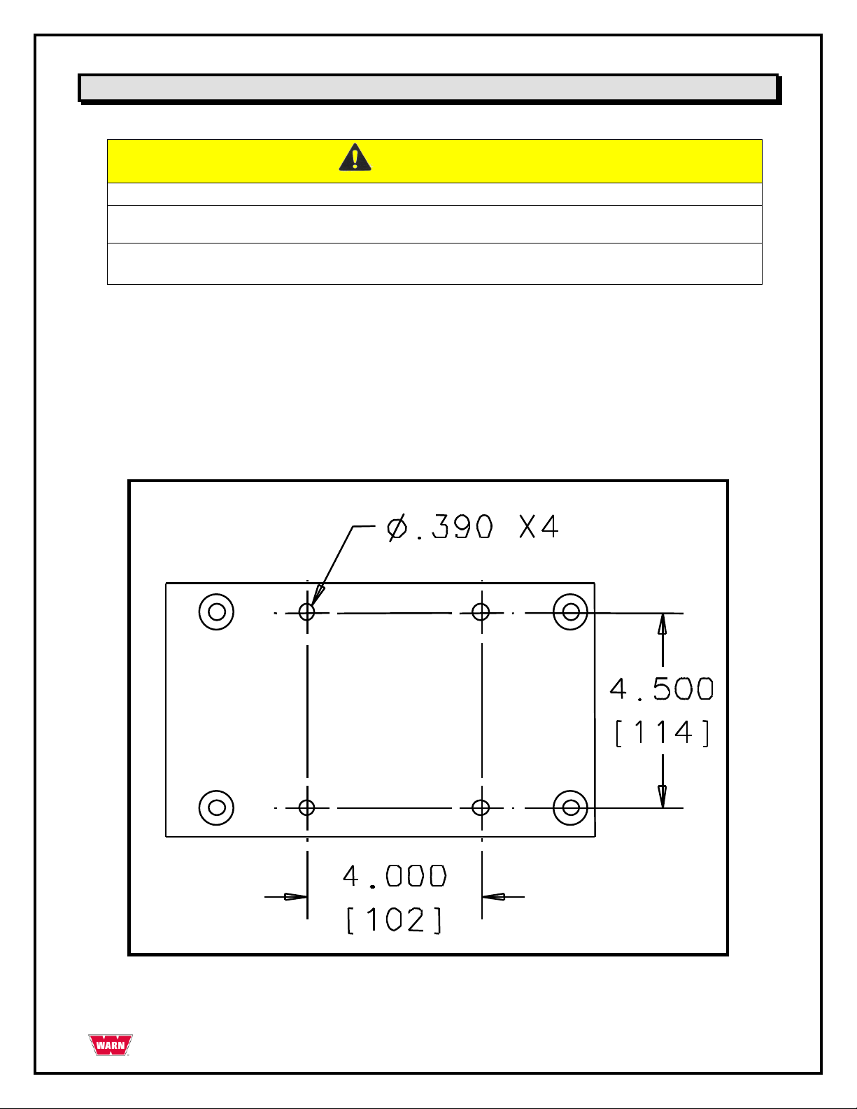
Winch Installation to fixed location
The 3000ACI can be mounted to a fixed location by untilizing the mounting hole pattern for the winch
unit. First, choose a mounting location that is sufficiently strong enough to withstand the loads you
intend to winch.
Next, drill 4 holes to the dimesions specified in the drawing below.
Mounting Plate Hole Pattern
PAGE 8 85366 Rev. A0
Page 9
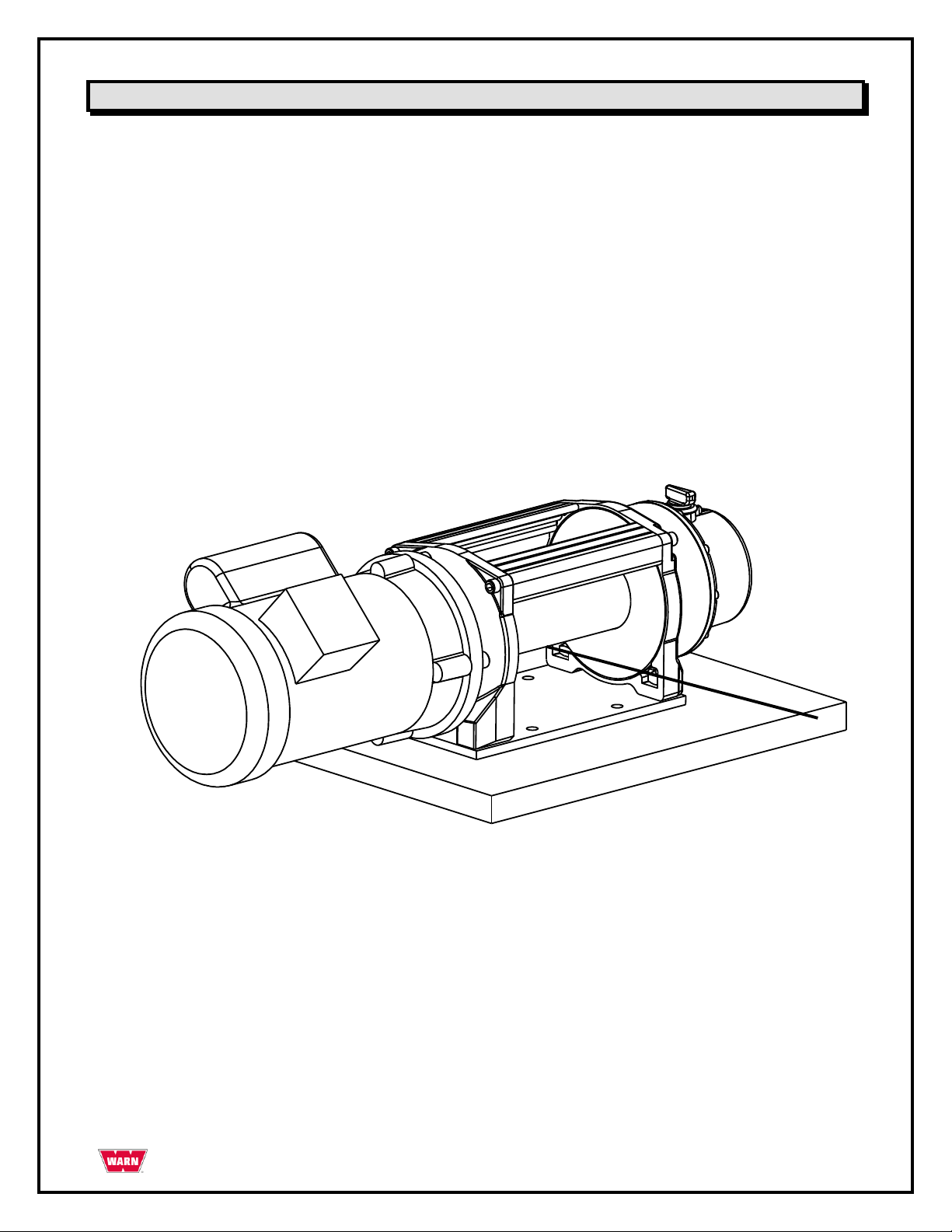
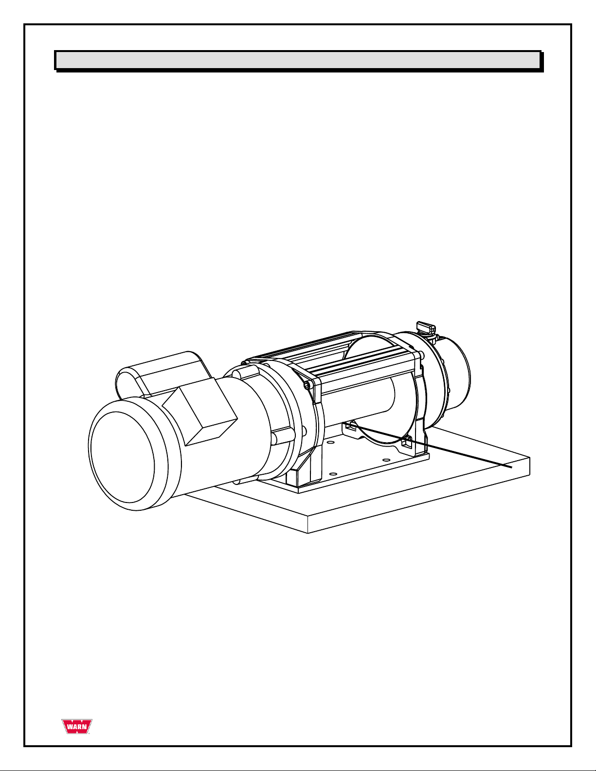
Winch Installation to a fixed location- continued
To secure the winch, always use:
▫ A flat, secure mounting location at least 3/16 in. (4.8 mm) thick steel.
▫ 3/8 in. lockwasher x 3.
▫ 3/8-18 x 1in. long, hex head capscrew, Grade 5 or better x 3.
▫ Torque mounting bolts to 30-35 ft-lbs (41-47 Nm).
Bolt length may need to be longer that specified above depending upon the thickness of the material the
winch is mounted to.
Acceptable Mounting Position
PAGE 9 85366 Rev. A0
Page 10
WARNING
Shock Hazard
Failure to observe these instructions could lead to severe injury or death.
Always have the winch wired by a qualified electrician
Always wire the winch in accordance with all local building and electrical codes.
Always use properly grounded 115 / 230 V AC receptacle protected by a ground fault
circuit interrupter (GFCI).
Never operate this AC product in a wet environment.
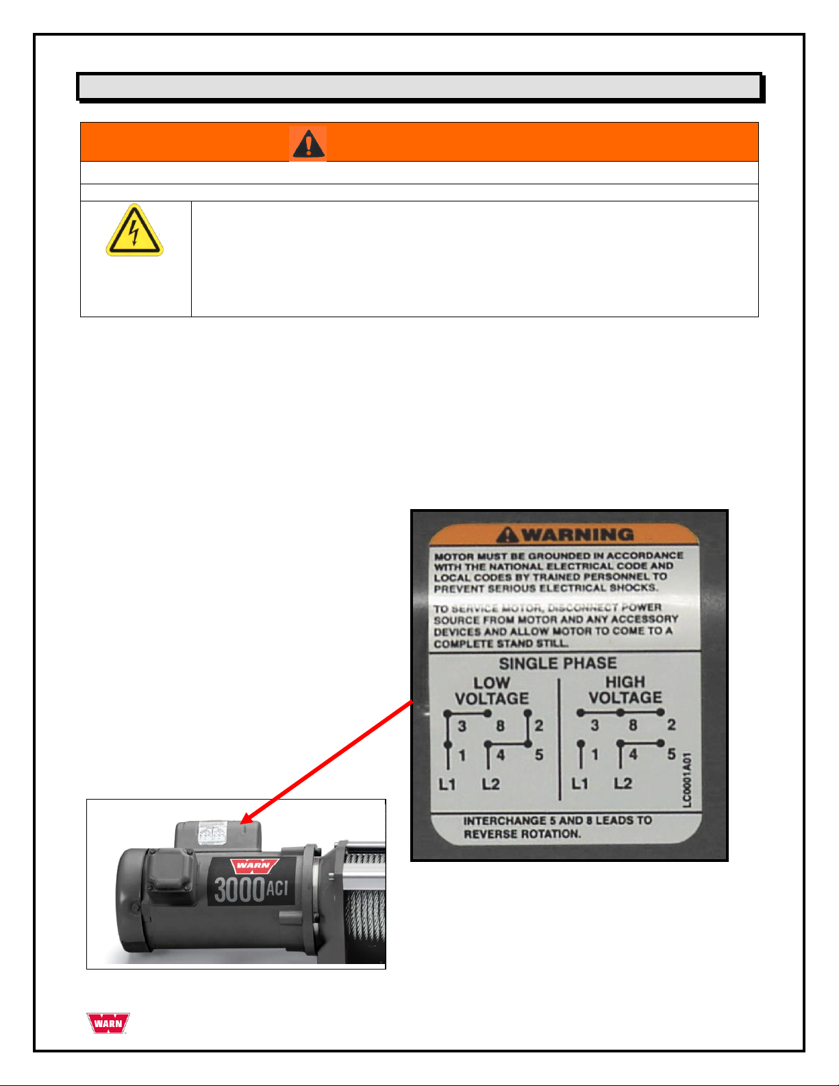
Wiring Instructions
Always have the winch wired by a qualified electrician and always wire the winch in accordance
with all local building and electrical codes.
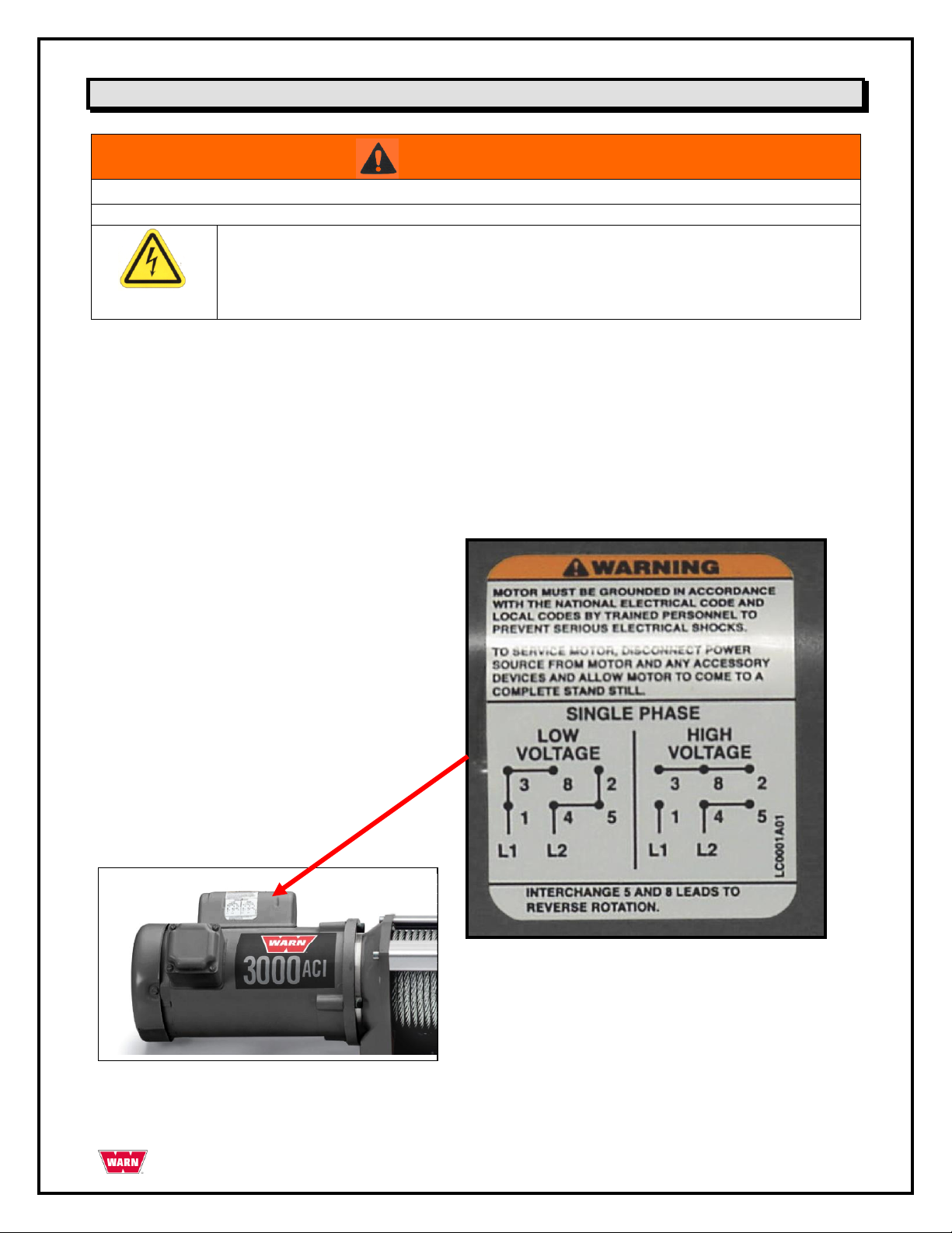
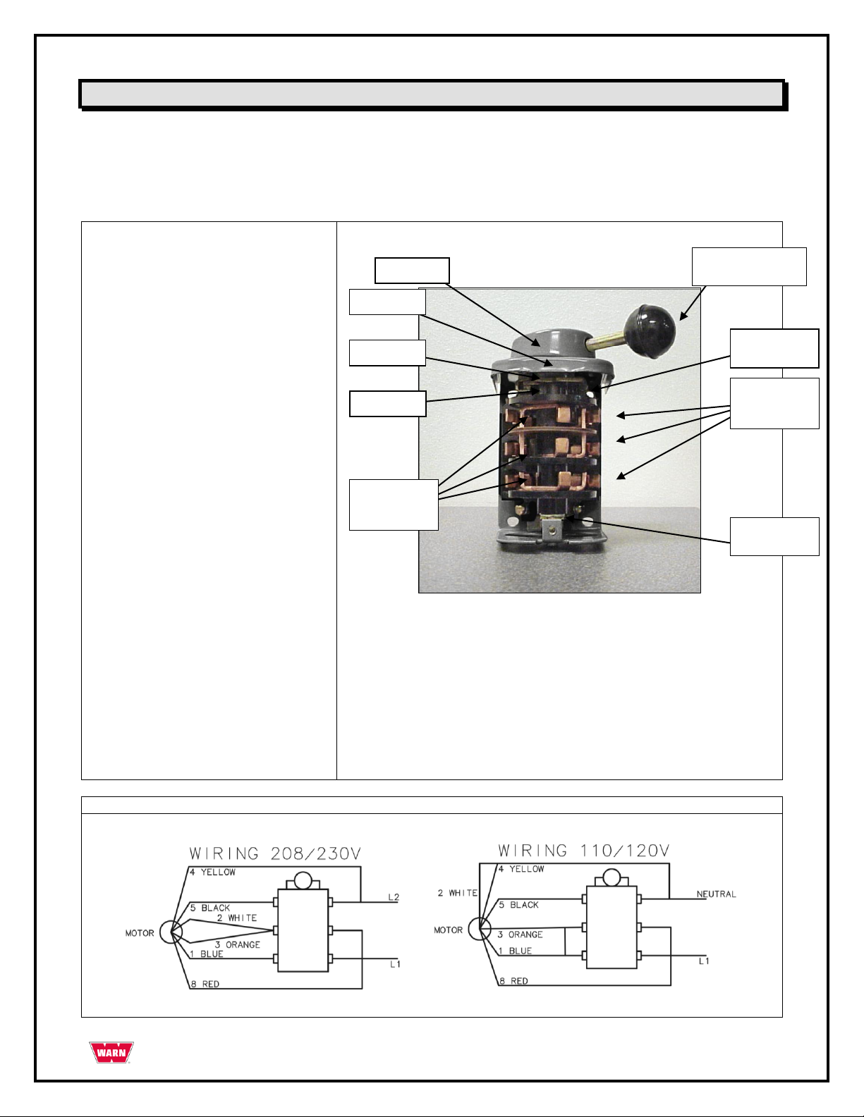
Winch Motor
Refer to the wiring diagram on the winch motor housing for the proper way to wire the motor to either 115
volt or 230 volt AC power source. A copy of those instructions and diagrams are inserted below for reference.
Always defer to the actual diagrams that are on the winch motor and in the Drum Switch.
PAGE 10 85366 Rev. A0
Page 11
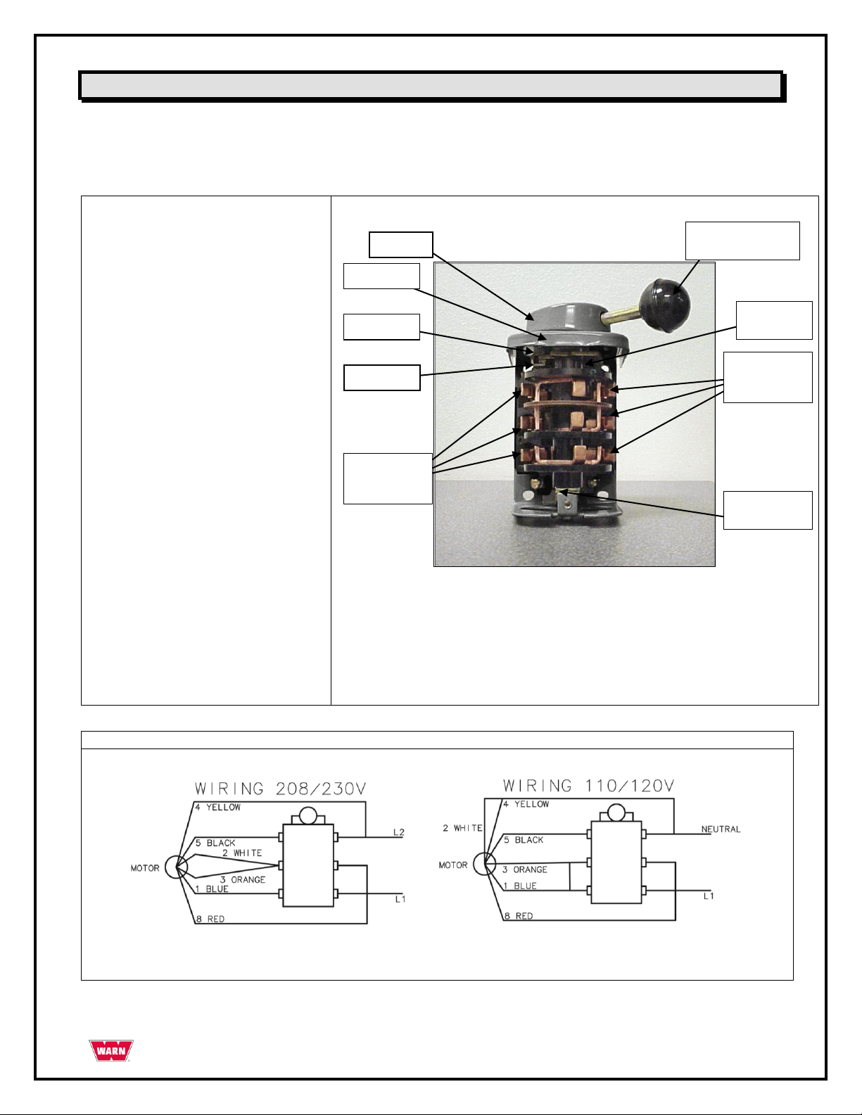
Caution: Before installing in a nuclear
application, determine that the product is intended
for such use.
Warning : Disconnect power before installing or
servicing.
Installation:
1. Mount the switch to a flat surface.
2. Connect the switch in accordance with the
wiring diagram provided in the instructions or
in the cover of the switch.
Note: Motor branch circuit protection should be
provided in accordance with the national electrical
code and local codes or ordinances.
Convertibility (Maintained to
Momentary)
To convert the CR102A1 drum switch or similar
switches from “Maintained Contact” to “ Spring
Return to OFF”, remove the operating knob (6)
from the hub(7) by turning in a counter clockwise
motion. Pry the hub from the shaft. Turn the
handle 180 degrees and replace the handle, knob
and the hub to the switch.
Mechanism Assembly
To disassemble the switch, remove the handle, hub
cover plate and stationary contacts. Remove the
two screws holding the case top and then lift off the
case top. Rotor assembly can then be removed.
Caution: Roller (3) is spring loaded and is loose
in arm (4). Caution must be exerted not to loose
the roller. Remove the roller from arm (4). To
reassemble, place the roller in the arm (4). Place
the rotor in the case by engaging the roller(3) with
the cam and inserting the shaft in the hole at the
bottom of the case. Reassemble by reversing the
above procedure
Figure 1. CR102A1
Wiring Diagram for 3000ACI and CR102A1
(2) Rotor
Assembly
(1)
Stationary
Contacts &
(2) Rotor
Assembly
(6) Operating
Handle & Knob
(5) Spring
(4) Arm
(3) Roller
(7) Hub
(1)
Stationary
Contacts &
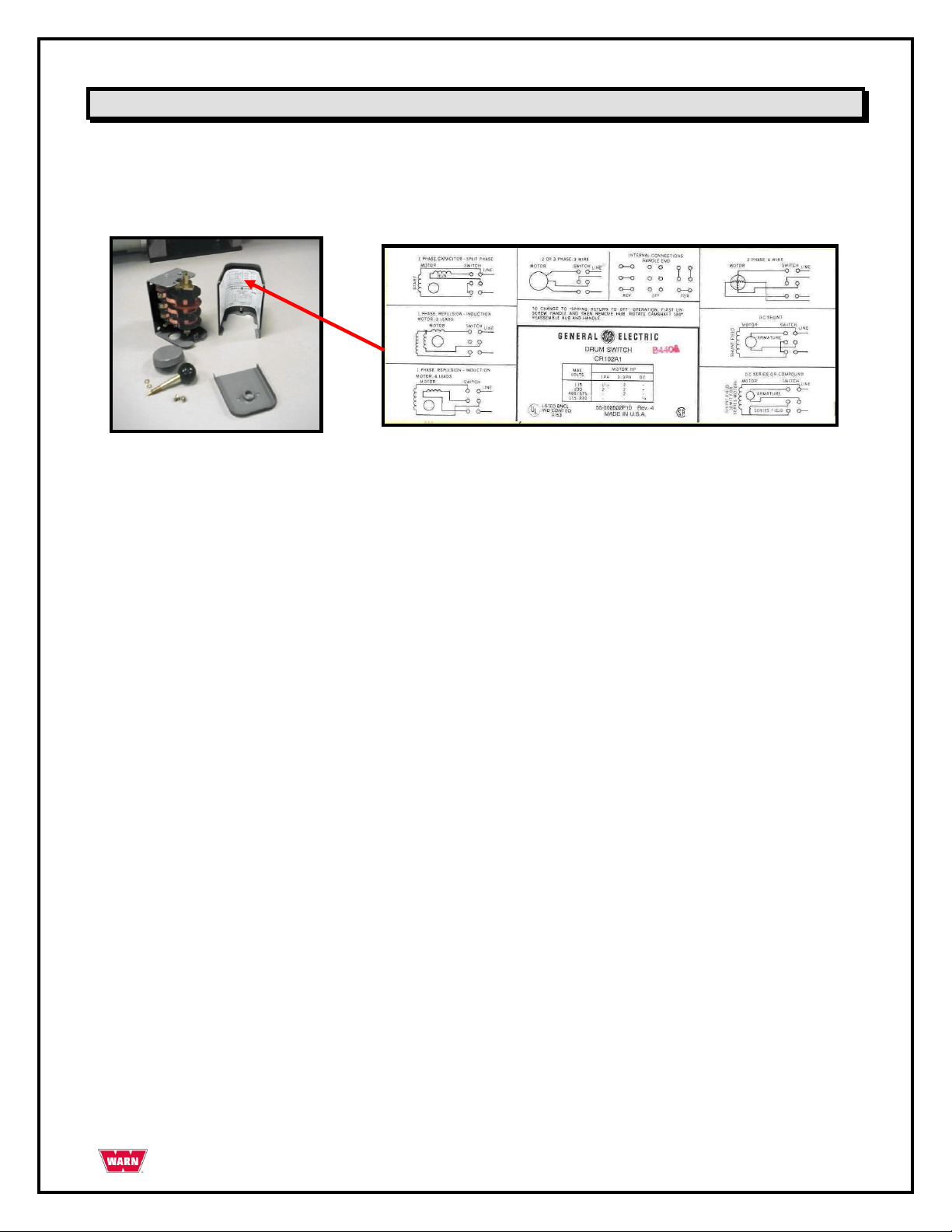
Wiring Instructions-continued
Switch Instructions
Refer to instructions enclosed with ―GE Drum Switch CR102A1 diagram for wiring schematics. A copy of
those instructions and diagrams are inserted below for reference. Always defer to the actual diagrams that
are on the winch motor and in the Drum Switch.
PAGE 11 85366 Rev. A0
Page 12

Wiring Instructions-continued
Switch Instructions
There is also a set of wiring diagrams inside the switch housing
Convert GE Drum Switch CR102A1 to ―Spring Return to OFF‖ configuration per instructions enclosed with
switch.
Verify that all wiring is positioned so that the wire rope or moving load will not damage it.
Always de-energize circuit when winch is not in use.
PAGE 12 85366 Rev. A0
Page 13
WARNING
Winch Function Hazard
Failure to observe these instructions could lead to injury or property damage
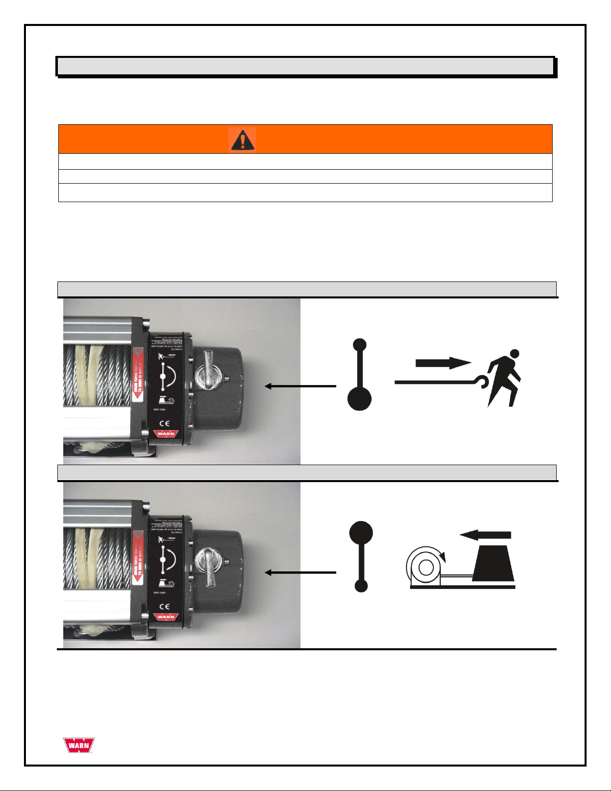
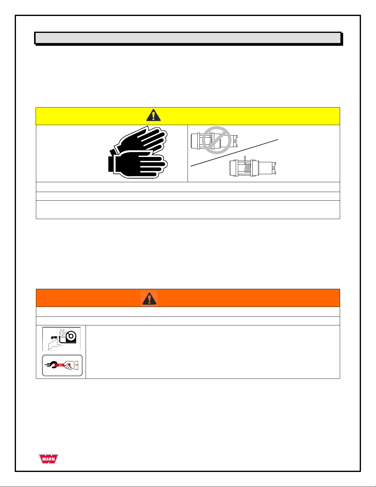
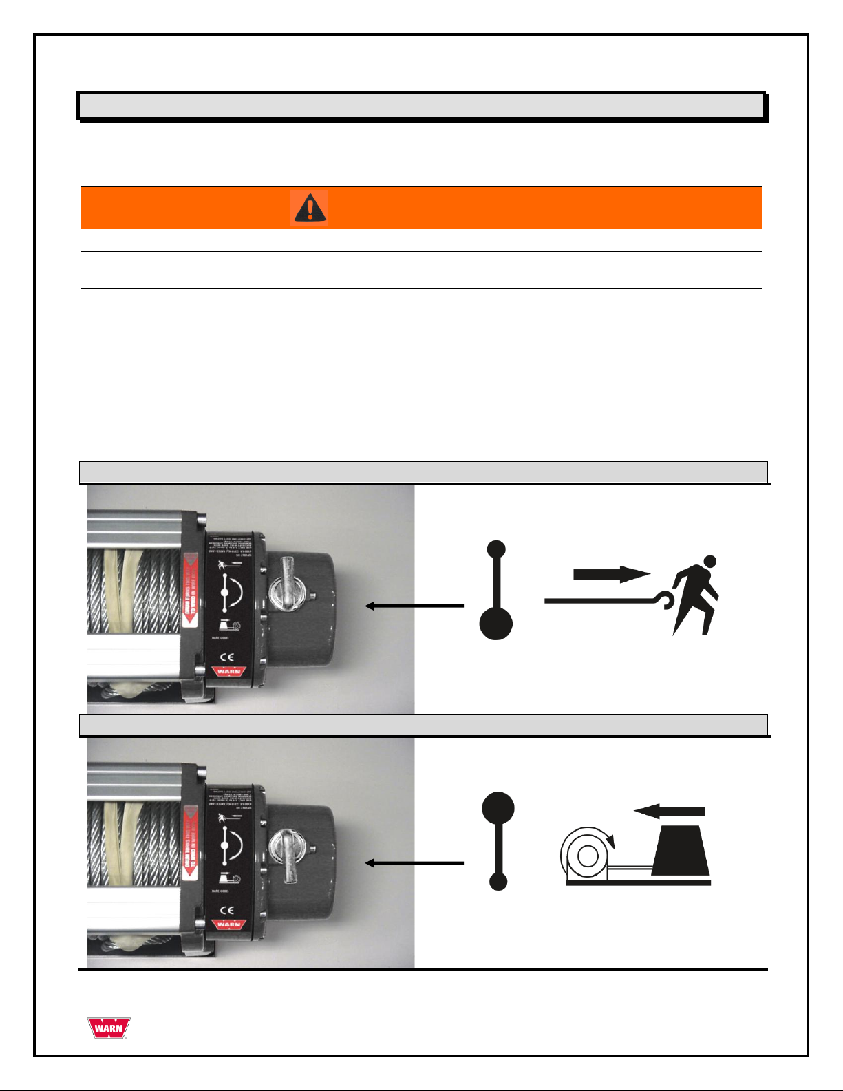
Never engage or disengage the clutch if the winch is underload or wire rope is under tension.
Disengage - Freespool
Engaged
Operating Instructions -
CLUTCH OPERATION
When the clutch is engaged the gear train is coupled to the wire rope drum and power may be transferred
from the winch motor. When the clutch is in freespool the gear train and wire rope drum are uncoupled
allowing the drum to rotate freely. The clutch lever, located on top of the motor, controls the clutch position.
To prevent damage, always fully engage or fully disengage the clutch lever.
PAGE 13 85366 Rev. A0
Page 14
CAUTION
Personal Injury Hazard
Failure to observe these instructions could lead to minor or moderate injury.
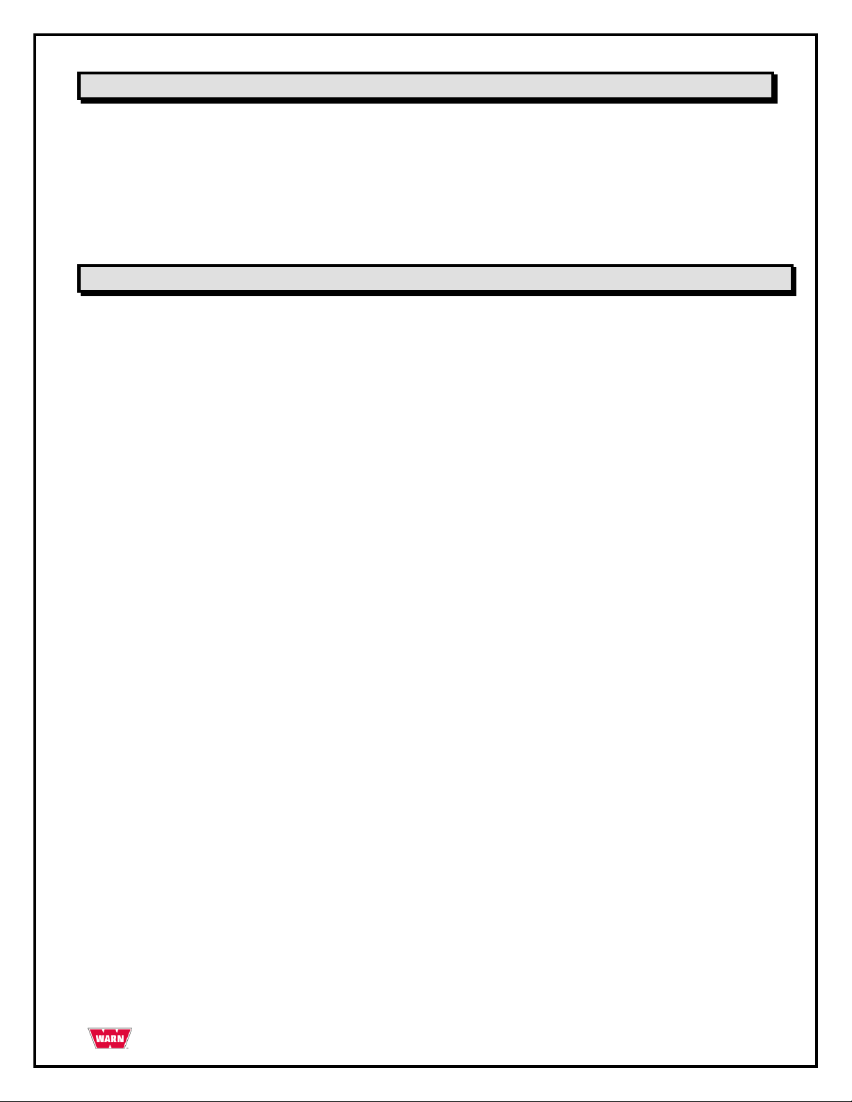
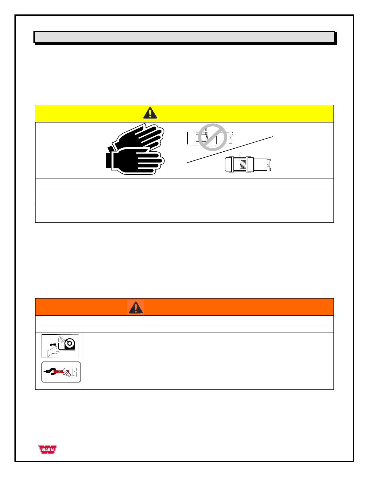
Always wear leather gloves when handling wire rope
Never winch with less than 5 wraps of wire rope around the drum.
WARNING
Moving Parts Entanglement Hazard
Failure to observe these instructions could lead to severe injury or death.
ALWAYS keep hands clear of the wire rope, hook loop, hook and fairlead opening
during installation, operation and when spooling in or out.
ALWAYS use supplied hook strap whenever spooling the wire rope in or out, during
installation, or operation to avoid injury to hands or fingers.
Operating Instructions - continued
SPOOLING OUT
Freespooling is generally the quickest and easiest way to spool out wire rope. Before freespooling wire rope
out from the winch, power out enough rope to remove any tension the wire rope may be under before
disengaging the clutch. Now freespool by manually spooling out enough wire rope for the winching
operation.
STRETCHING THE WIRE ROPE
The life of a wire rope is directly related to the care and use it receives. During its first use, a new wire rope
must be spooled onto its drum under a load of at least 500 lb. (227kg). Spool out the entire wire rope length
leaving 5 wraps on the drum, then power in the wire rope under a load of 500 lb. (227kg) or more. This will
stretch new wire rope and create a good wire wrap around the drum. Failure to do so may result in the outer
wire wraps drawing into the inner wraps, binding, and damaging the wire rope.
PAGE 14 85366 Rev. A0
Page 15

Operating Instructions - continued
SPOOLING IN UNDER LOAD
The wire rope must always spool onto the bottom of the drum as indicated by decal on the winch.
Power in the wire rope evenly and tightly on the drum. This prevents the outer wire wraps from
drawing into the inner wraps, binding and damaging the wire rope.
Avoid shock loads when spooling, by using the control switch intermittently to take up wire rope
slack. Shock loads can momentarily far exceed the winch and wire rope ratings.
SPOOLING IN UNDER NO LOAD
Assisted: Have your assistant hold the hook with the hook strap putting as much constant tension
on the wire rope as possible. While keeping tension, the assistant should walk toward the winch
while you operate the control switch spooling in the wire rope. Release the switch when the hook is
a minimum of 4 ft (1.2m) from the fairlead opening. Spool in the remainder for storage.
Unassisted: Arrange the wire rope to be spooled so it will not kink or tangle when spooled. Be sure
any wire rope on the drum is tightly and evenly layered. Spool enough wire rope to complete the next
full layer on the drum. Tighten and straighten the layer. Repeat process until the hook is a minimum
of 4ft (1.2m) from the fairlead. Spool in the remainder for storage.
SPOOLING REMAINDER FOR STORAGE
Keep hands clear of the wire rope, hook and fairlead opening. Always use the hook strap to hold hook when
spooling under no load. Carefully power in the remaining wire rope, jogging the control switch to take up the
last of the slack. Secure the hook to a suiteable anchor point near the winch. Be careful not to overtighten
or damage may occur to the wire rope or anchor point.
RIGGING
Always spool out as much wire rope as possible when preparing rigging. Pick an anchor as far away
as is practical; this provides the winch with its greatest pulling power.
Rigging a double line with a snatch block will reduce the load on the winch to half without significant
loss of spooling speed.
Natural anchors such as trees, stumps and rocks are the handiest when available. Attach the choker
chain, wire choker rope or tree trunk protector on the anchor as low as possible to avoid pulling the
anchor down. If several possible anchors are available but they are not strong enough individually, it
may be practical to attach a wire or chain choker around several anchors to form a strong collective
anchor point.
PAGE 15 85366 Rev. A0
Page 16
Operating Instructions - continued
OVERLOADING/OVERHEATING
This winch is rated for intermittent duty. It should not be operated with the motor slowed down to a low
RPM. When the motor approaches stall speed, a very rapid heat build-up occurs which may cause motor
damage. Double line rigging will reduce the amperage draw from the motor allowing longer continual use
(see rigging section).
Maintenance & Warranty
MAINTENANCE
No lubrication is required for the life of the winch.
Inspect the wire rope before and after each winching operation. Replace when damaged.
WARRANTY
see separate sheet packed with winch
-or-
If warranty sheet is lost or misplaced contact:
Warn Industries, Inc.
Customer Service Dept.
12900 SE Capps Rd
Clackamas, OR 97015-8903.
United States:
Phone: 503.722.1200 or (800) 543-9276 (US only)
Fax: 503.722-3000
International:
Phone: 503.722.3008
Fax: 503.722.3005
© 2010 Copyright Warn Industries, Inc. All rights reserved.
PAGE 16 85366 Rev. A0
Page 17

GUÍA DEL CABRESTANTE PARA EL USUARIO
Cabrestante de uso general WARN® 3000ACI
Nº DE REFERENCIA: 93000
PAGE 17 85366 Rev. A0
Page 18
Su seguridad y la seguridad de los demás es muy importante. Para ayudarle a tomar decisiones informadas sobre seguridad, se
proporcionan instrucciones de instalación y operación, y otra información en etiquetas Esta información le alerta sobre posibles peligros
que puedan afectarle a usted y a otros. No es posible advertirle sobre todos los posibles peligros que puedan estar relacionados con el
uso de este producto, por lo que deberá utilizarlo usando el sentido común.
LA INSTALACIÓN Y OPERACIÓN INCORRECTAS DEL CABRESTANTE PUEDEN RESULTAR EN LESIONES GRAVES O DAÑOS
AL EQUIPO. LEA TODAS LAS PRECAUCIONES DE SEGURIDAD E INSTRUCCIONES DE OPERACIÓN ANTES DE INSTALAR Y
PONER EN FUNCIONAMIENTO ESTE PRODUCTO.
Esta guía identifica posibles peligros y brinda importantes mensajes de seguridad que le ayudarán a usted y a otros a evitar daños
personales o la muerte. Las palabras ADVERTENCIA y PRECAUCIÓN indican el grado de peligro. He aquí su significado:
ADVERTENCIA indica un peligro que
recomendaciones.
PRECAUCIÓN indica un peligro que
recomendaciones.
Esta guía emplea la palabra
poner énfasis sobre información general digna de especial atención.
AVISO
para llamar la atención sobre importante información de carácter mecánico, y la palabra Nota: para
puede
ocasionar daños personales de gravedad o la muerte si no se siguen las
puede
ocasionar daños personales leves o moderados si no se siguen las
Descripción del producto: Cabrestante de uso general WARN® 3000ACI
El cabrestante de uso general 3000ACI de WARN es una poderosa herramienta de arrastre. Accionado por
una fuente de energía de 115/230 voltios de CA, este compacto cabrestante tiene una capacidad de tiro de
1361 kilos (3000 libras).
Introducción
Gracias por su adquisición del modelo de WARN para sus necesidades generales de arrastre e izado. Todos
los productos de WARN® se han diseñado y manufacturado para una operación sin problemas durante
muchos años. Para referencia futura, guarde la siguiente información en un lugar seguro:
Modelo/Nº de referencia: Fecha de compra:
Antes de comenzar
Lea las instrucciones en su totalidad para familiarizarse con el proceso de instalación.
Revise todos los avisos, precauciones y advertencias para asegurarse de que el conjunto se instala
correcta y seguramente.
PAGE 18 85366 Rev. A0
Page 19
ADVERTENCIA
PELIGRO DE ENREDO EN LAS PIEZAS MÓVILES
De no seguirse estas instrucciones podrían producirse lesiones graves o la muerte.
Para evitar daños en las manos.
--Mantenga siempre las manos alejadas del cable, del bucle del gancho, del gancho y de la abertura de la guía durante la
instalación, la operación, y en el enrollado y desenrollado.
• Use siempre precaución extrema en el manejo del gancho y el cable durante las operaciones de enrollado y
desenrollado.
• Use siempre la correa del gancho suministrada cuando vaya a enrollar o desenrollar el cable durante la instalación o la
operación para evitar lesiones en las manos.
ADVERTENCIA
PELIGRO DE CAÍDA O APLASTAMIENTO
De no seguirse estas instrucciones podrían producirse lesiones graves o la muerte.
• No utilice nunca el cabrestante como grúa vertical, ni para suspender una carga.
• No utilice nunca el cabrestante para levantar o desplazar personas.
Precauciones de seguridad
A continuación se indican algunas precauciones generales de seguridad que toda persona que vaya a usar el
cabrestante debe conocer. La norma más importante, por encima de todas las demás: USE EL SENTIDO
COMÚN.
Unos pocos minutos empleados en leer estas normas pueden hacer que el operario tome conciencia de
acciones peligrosas que deben evitarse y de las precauciones a tomar para su propia seguridad y la seguridad
de los demás. Las revisiones frecuentes y las inspecciones periódicas del equipo, así como un seguimiento
consciente de las reglas de seguridad pueden salvar vidas, y también ahorrar tiempo y dinero.
PAGE 19 85366 Rev. A0
Page 20
Precauciones de seguridad – Continuación
PRECAUCIÓN
PELIGRO DE ENREDO EN LAS PIEZAS MÓVILES
De no seguirse estas instrucciones podrían producirse lesiones menores o de poca gravedad.
Seguridad general:
• Sea siempre consciente del funcionamiento del cabrestante: Tómese su tiempo para leer y comprender completamente la guía de
Instalación y operaciones, y la Guía básica de técnicas del cabrestante, que vienen con el mismo, para poder comprender el
funcionamiento del cabrestante.
• No haga funcionar nunca este cabrestante si usted es menor de 16 años de edad.
• No haga funcionar nunca el cabrestante si se encuentra bajo la
influencia de drogas, alcohol o medicamentos.
• No exceda nunca la capacidad nominal del cabrestante ni del cable de tiro. Emplee un cable doble utilizando una polea pasteca
para reducir la carga del cabrestante.
Seguridad para la instalación:
• Elija siempre una ubicación de montaje que sea lo suficientemente sólida para soportar la capacidad de carga máxima del
cabrestante.
• Utilice siempre interruptores, controles remotos, accesorios y componentes de instalación que estén aprobados de fábrica.
• Utilice siempre tornillería de grado 5 o superior, pernos que nunca hayan sido soldados y no utilice nunca pernos que sean más
largos que los suministrados por la fábrica.
• Complete siempre el montaje y acoplamiento del gancho del cabrestante al bucle del gancho antes de cablear el cabrestante
durante la instalación.
• Ponga siempre la guía del cable con la etiqueta de ADVERTENCIA en su parte superior.
• Enrolle y desenrolle el cable en el tambor siempre según lo
indicado por la etiqueta de rotación del tambor del cabrestante. Es necesario para que funcione el freno automático (si viene con el
cabrestante) y para una orientación correcta de la instalación.
• Realice siempre un estiramiento previo del cable y vuelva a enrollarlo con carga antes de usarlo. Un cable bien enrollado reduce el
riesgo de ―agarrotamiento‖, que consiste en el cable enrollándose en una capa de cable que está enrollada flojamente, y
enganchándose o dañándose a sí mismo.
Seguridad en el enrollado y desenrollado:
• Revise siempre la instalación del cabrestante y el estado del cable antes de su uso. Si el cable está deshilachado, retorcido o
dañado, deberá reemplazarse de inmediato. Cualquier pieza instalada que esté suelta o dañada deberá corregirse de inmediato.
• No enganche nunca el cable sobre sí mismo. Esto deterioraría el cable. Utilice una cadena o un cable de estrangulación, o un
protector de tronco de árbol en el anclaje.
• Antes del enrollado, no olvide nunca retirar cualquier elemento que pueda interferir con una operación del cabrestante segura.
• Tómese su tiempo siempre cuando utilice un cabrestante.
• Verifique siempre que el anclaje seleccionado soportará la carga y que la correa o la cadena no se deslizará.
• Nunca embrague ni desembrague si el cabrestante está soportando una carga, si el cable está en tensión o si el tambor del cable
está en movimiento.
• Siempre desenrolle tanto cable como sea posible al prepararse para el maniobrado. Emplee un cable doble o elija un punto de
anclaje distante.
• No accione nunca el cabrestante si no hay al menos 5 vueltas de cable alrededor del
tambor. El cable podría soltarse del tambor ya que el dispositivo de sujeción del cable al tambor no es apto para soportar una carga.
• Manténgase siempre alejado del cable y de la carga durante el accionamiento del cabrestante.
• No toque nunca el cable ni el gancho mientras éstos estén en tensión o con carga.
• No toque nunca el cable ni el gancho si hay alguien cerca del interruptor de control, o si el cabrestante está en funcionamiento.
• No toque nunca el cable ni el gancho si el control remoto está enchufado al cabrestante.
• Manténgase siempre alejado del cable y de la carga, y no deje que otros se acerquen mientras el cabrestante esté en
funcionamiento.
• Haga que el operario y otras personas presentes sean conscientes de la estabilidad durante la operación del cabrestante en el
manejo del vehículo o la carga.
• Mantenga siempre el cable del control remoto alejado del tambor, del cable y del maniobrado. Inspeccione la posible existencia de
grietas, pellizcos, cables deshilachados o conexiones sueltas. Reemplácelo si está dañado.
PAGE 20 85366 Rev. A0
Page 21

PRECAUCIÓN
PELIGRO DE CORTES Y QUEMADURAS
De no seguirse estas instrucciones podrían producirse lesiones menores o de poca gravedad.
Para evitar daños en las manos:
Lleve puestos siempre guantes gruesos de cuero para manejar el cable.
Nunca deje que el cable se deslice por sus manos.
Tenga siempre en cuenta que las superficies del motor, del tambor o del cable del cabrestante pueden estar
calientes durante o después del uso del mismo.
PRECAUCIÓN
Peligro de enredo en las piezas móviles
De no seguirse estas instrucciones podrían producirse lesiones menores o de poca gravedad.
No aplique nunca la carga a la punta del gancho o al seguro del mismo. Aplique la carga únicamente en el centro
del gancho.
No utilice nunca un gancho cuya abertura haya aumentado, o cuya punta esté doblada o retorcida
AVISO
EVITE DAÑOS AL EQUIPO Y AL CABRESTANTE
• Evite siempre los tirones laterales continuos ya que pueden apilar el cable en un extremo del tambor. Esto puede
dañar el cable o el cabrestante.
• Compruebe siempre que se ha embragado o desembragado completamente.
• No utilice nunca el cabrestante para remolcar otros vehículos. Las cargas repentinas pueden exceder
momentáneamente la capacidad del cable y el cabrestante.
• Sea precavido siempre para no dañar la estructura cuando vaya a anclar su vehículo en una operación con el
cabrestante.
• No desplace nunca el cable en pequeñas sacudidas cuando esté con carga. Las cargas repentinas pueden exceder
momentáneamente la capacidad del cable y el cabrestante.
• Nunca utilice el cabrestante para amarrar una carga durante el transporte.
• No sumerja nunca el cabrestante en agua.
• Guarde siempre el cabrestante en un área protegida, limpia y seca.
Precauciones de seguridad - Continuación
PAGE 21 85366 Rev. A0
Page 22
1. Potente motor de inducción TEFC de 0,75 CV
2. Tambor de gran tamaño con cable de 2,54 m (100 pulg)
de largo y 8 mm (5/16 pulg) de diámetro
3. Tren de engranajes planetario de 3 fases con
embrague
4. Interruptor de control tipo estación
5. Paquete de accesorios con gancho de presilla
1 2 3
4
5
Lista de piezas
El cabrestante de uso general 3000ACI de WARN consta de los siguientes componentes principales.
Dimensiones del modelo WARN 3000ACI
PAGE 22 85366 Rev. A0
Page 23
Características:
Capacidad de tracción
1361 kg. (3000 lb)
Freno
Frenado dinámico y mecánico
Tipo de interruptor
Interruptor de tambor / Tipo estación
Garantía
Limitada de 1 año
Motor
Motor de inducción TEFC de CA
Cable
7,94 mm (5/16 pulg) X 30,5 m (100 pies)
CV
0,75 CV 56C
Diámetro del
tambor
6,35 cm (2,5 pulg)
Potencia
CA, monofásico de 115/230 voltios y 50/60
hercios.
Guía
Ninguna
Tren de engranajes
Planetario de 3 fases
Esquema de los
orificios
4 orificios
Relación de
transmisión
216:01
Conexiones
eléctricas
Ninguna
Embrague
Engranaje con anillo deslizante accionado por
palanca
Peso
34,5 kg (76lbs)
ESPECIFICACIONES TÉCNICAS: 3000ACI
115 V 60 Hz Monofásico
Carga
Corriente
Velocidad
Potencia de tiro por capa de cable
libras
Kg
Amperios
KW
pies/min
m/min
Capa
libras.
kg
0 0 9.1
1049
12.2
3.7
1
3000
1361
1000
453.6
11.0
1265
8.8
2.7
2
2700
1225
1500
680.4
12.7
1461
8.8
2.7
3
2460
1116
2000
907.2
14.8
1702
8.6
2.6
4
2250
1021
2500
1134
17.7
2036
8.5
2.6
5
2070
939
3000
1360.8
20.9
2300
8.1
2.5
ESPECIFICACIONES TÉCNICAS: 3000ACI
230 V 50 Hz Monofásico
Carga
Corriente
Velocidad
Potencia de tiro por capa de cable
libras
Kg
Amperios
KW
pies/min
m/min
Capa
libras
kg
0 0 4.6
1058
12.2
3.7
1
3000
1361
1000
453.6
5.5
1265
8.8
2.7
2
2700
1225
1500
680.4
6.4
1472
8.8
2.7
3
2460
1116
2000
907.2
7.4
1702
8.6
2.6
4
2250
1021
2500
1134
8.9
2047
8.5
2.6
5
2070
939
3000
1360.8
10.5
2415
8.1
2.5
Especificaciones para el modelo WARN 3000ACI
Especificaciones técnicas para el modelo WARN 3000ACI
PAGE 23 85366 Rev. A0
Page 24
PRECAUCIÓN
Peligro del fallo del cabrestante
De no seguirse estas instrucciones podrían producirse lesiones menores o de poca
gravedad.
Elija un lugar de montaje que sea lo suficientemente resistente para soportar las cargas que
desee elevar con el cabrestante.
Instalación del cabrestante en una ubicación fija
El modelo 3000ACI puede montarse en una ubicación fija usando el patrón de agujeros de montaje para
la unidad del cabrestante. Elija un lugar de montaje que sea lo suficientemente resistente como para
soportar las cargas que desee desplazar.
A continuación, haga tres taladros según las dimensiones especificadas en la ilustración siguiente.
Esquema de los orificios de la placa para el montaje
PAGE 24 85366 Rev. A0
Page 25
Instalación del cabrestante en una ubicación fija - Continuación
Para asegurar el cabrestante utilice siempre:
▫ Un lugar plano y seguro para el montaje de por lo menos 4,8 mm (3/16 pulg) de grosor.
▫ Una arandela de bloqueo de 3/16 pulg. x 3.
▫ Un tornillo de cabeza hexagonal de 3/8-18 x 1 pulg. de largo, de grado 5 ó mejor x 3.
▫ Apriete los pernos de montaje con un par de torsión de 41-47 Nm (30-35 pies-lbs).
Es posible que la longitud del perno deba ser más larga que la especificada anteriormente, dependiendo del
grosor del material en el que esté montado el cabrestante.
Posición de montaje aceptable
PAGE 25 85366 Rev. A0
Page 26
ADVERTENCIA
Peligro de electrocución
De no seguirse estas instrucciones, podrían producirse lesiones de gravedad o la muerte.
El cableado del cabrestante deberá ser instalado siempre por un electricista
competente
El cableado de cabrestante ha de instalarse siempre de acuerdo con los códigos de
construcción y eléctricos locales.
Ha de utilizarse siempre un receptáculo de 115/230 voltios de CA con adecuada
conexión a tierra, protegido por un interruptor de averías con conexión a tierra.
No haga funcionar este producto activado por CA en un ambiente húmedo.
Instrucciones de cableado
El cableado del cabrestante deberá ser instalado siempre por un electricista competente, y ha de
hacerse siempre de acuerdo con los códigos de construcción y eléctricos locales.
Motor del cabrestante
Consulte el diagrama de cableado que se encuentra en la cubierta del motor del cabrestante, que indica las
instrucciones para el cableado a una toma de CA de 115 o 230 voltios. A continuación encontrará una copia
de tales instrucciones y diagramas de referencia. Consulte siempre los diagramas que se encuentran en el
motor del cabrestante y en el interruptor del tambor.
PAGE 26 85366 Rev. A0
Page 27
Precaución: Antes de instalarlo en una
aplicación de uso nuclear, determine si el
producto ha sido diseñado para tal uso.
Advertencia: Antes de instalarlo o darle
mantenimiento, desconecte la alimentación
eléctrica
Instalación:
1. Monte el interruptor en una superficie
plana.
2. Conecte el interruptor según lo indicado en
el diagrama de cableado que viene en las
instrucciones y en la cubierta del
interruptor.
Nota: Deberá protegerse el circuito derivado del
motor según lo dispuesto por el código nacional
y los códigos y ordenanzas eléctricos locales.
Convertibilidad (mantenida en
momentánea)
Para convertir el interruptor del tambor
CR102A1 o interruptores similares de “Contacto
mantenido” a “Retorno de muelle a APAGADO”,
quite la perilla de operación (6) del cubo (7)
girándolo en sentido opuesto a las manecillas del
reloj. Apalanque el cubo alejándolo del eje. Gire
el mango 180 grados y vuelva a poner el mango,
la perilla y el cubo en el interruptor.
Montaje del mecanismo
Para desmontar el interruptor, retire el mango, la
placa de la cubierta del cubo y los contactos
estacionarios. Quite los dos tornillos que sujetan
parte superior de la carcasa y levántela. El
conjunto del rotor podrá desmontarse entonces.
Precaución: El rodillo (3) tiene un muelle y está
flojo en el brazo (4). Debe tenerse cuidado de no
aflojar el rodillo. Retire el rodillo del brazo (4).
Para volver a montarlo, ponga el rodillo en el
brazo (4). Ponga el rotor en la carcasa acoplando
el rodillo (3) a la leva e insertando el eje en el
agujero que se encuentra en la parte inferior de
la carcasa. Vuelva a montarlo invirtiendo el
procedimiento anterior.
Figure 1. CR102A1
Cableado -3000ACI
(2) Rotor
Assembly
(1) Contactos
y soporte
estacionarios
(2) Conjunto
del rotor
(6) Mango y perilla
de operación
(5) Muelle
(4) Brazo
(3) Rodillo
(7) Cubo
(1) Contactos
y soporte
estacionarios
Instrucciones de cableado (continuación)
Instrucciones del interruptor
Consulte las instrucciones que vienen en el diagrama del interruptor de tambor GE, modelo CR102A1, para
verificar el cableado. A continuación encontrará una copia de tales instrucciones y diagramas de referencia.
Consulte siempre los diagramas que se encuentran en el motor del cabrestante y en el interruptor del
tambor.
PAGE 27 85366 Rev. A0
Page 28
Instrucciones de cableado (continuación)
Instrucciones del interruptor
También encontrará una serie de diagramas de cableado en el interior de la cubierta del interruptor
Convierta el Interruptor de tambor GE, modelo CR102A1, a la configuración de ―Retorno de muelle a
APAGADO‖ siguiendo las instrucciones que vienen con el interruptor.
Compruebe que todo el cableado esté dispuesto de forma que ni el cable del cabrestante ni la carga lo dañen
al moverse.
Desconecte siempre la alimentación del circuito cuando no se esté usando el cabrestante.
PAGE 28 85366 Rev. A0
Page 29
ADVERTENCIA
Peligro durante el funcionamiento del cabrestante
De no seguirse estas instrucciones podrían producirse lesiones de gravedad o la
muerte.
No embrague ni desembrague nunca si el cabrestante se encuentra con carga o si el cable tiene
tensión.
Desactivado – Enrollado libre
Activado
Instrucciones de operación
ACCIONAMIENTO DEL EMBRAGUE
Cuando el embrague está activado, el sistema de engranajes se acopla al tambor del cable y, en estas
condiciones, puede transferirse movimiento desde el motor del cabrestante. Cuando el embrague está en el
modo de enrollado libre, el sistema de engranajes y el tambor del cable están desengranados, lo que permite
que el tambor gire libremente. La palanca del embrague, situada en la parte superior del motor, controla la
posición del mismo. Para evitar daños, engrane y desengrane siempre completamente la palanca del
embrague.
PAGE 29 85366 Rev. A0
Page 30
PRECAUCIÓN
Peligro de lesiones
De no seguirse estas instrucciones podrían producirse lesiones menores o de poca
gravedad.
Lleve puestos siempre guantes gruesos de cuero para manipular el cable.
No accione el cabrestante si no hay al menos 5 vueltas de cable alrededor del tambor.
ADVERTENCIA
Peligro de enredo en las piezas móviles
De no seguirse estas instrucciones podrían producirse lesiones de gravedad o la muerte.
Mantenga siempre las manos alejadas del cable, del bucle del gancho, del gancho y
de la abertura de la guía durante la instalación, la operación, y en el enrollado y
desenrollado.
Utilice siempre la correa del gancho suministrada cuando vaya a enrollar o
desenrollar el cable, o durante la instalación o la operación, para evitar daños en las
manos.
Instrucciones de operación - Continuación
DESENROLLADO
Generalmente, el desenrollado manual es la forma más rápida y sencilla de sacar el cable hacia afuera. Antes
de proceder al desenrollado manual, saque suficiente cable a fin de eliminar cualquier tensión en la que
pueda estar sometido el mismo antes de desembragar. A continuación, proceda al desenrollado manual,
sacando manualmente suficiente cable para la operación.
TENSIÓN DEL CABLE
La vida útil del cable está directamente relacionada con la forma en que se utiliza y se cuida el mismo.
Durante su primer uso, un cable nuevo debe enrollarse en su tambor bajo una carga de por lo menos 227 kg
(500 libras). Desenrolle todo el cable dejando 5 vueltas en el tambor y a continuación, enrolle el cable bajo
una carga de 227 kg (500libras) o más. Esto tensará el cable nuevo y creará un correcto enrollado del mismo
alrededor del tambor. De no hacerse así, las vueltas exteriores se podrían trabar con las vueltas interiores
produciendo atascamientos y daños en el cable.
PAGE 30 85366 Rev. A0
Page 31

Instrucciones de operación - Continuación
ENROLLADO CON CARGA
El cable debe enrollarse alrededor del tambor en el sentido indicado por la marca de rotación que hay
en el cabrestante.
Enrolle el cable uniformemente y bien tensado alrededor del tambor. Esto evita que las vueltas más
externas del cable se traben con las vueltas internas, lo cual puede ocasionar atascamientos y daños
al cable.
Evite las sacudidas de la carga cuando esté enrollando; para ello, utilice el interruptor de control de
forma intermitente a fin de tensar y hacer entrar las porciones del cable que puedan quedar flojas.
Las sacudidas de la carga pueden sobrepasar momentáneamente la capacidad nominal del
cabrestante y del cable.
ENROLLADO SIN CARGA
Con asistencia: Pida a su ayudante que sujete el gancho y la correa del mismo, tensando el cable
de forma constante y tanto como sea posible. Manteniendo tenso el cable, el ayudante debe caminar
hacia el cabrestante mientras usted acciona el interruptor de control para enrollar el cable. Suelte el
interruptor cuando el gancho esté a una distancia mínima de 1,2 m (4 pies) de la abertura de la guía.
Luego, enrolle la parte final del cable para su almacenamiento.
Sin asistencia: Disponga el cable de forma que no se doble ni se trabe al enrollarlo. Asegúrese de
que el cable ya enrollado alrededor del tambor esté bien tenso y dispuesto en capas uniformes.
Enrolle el cable lo suficiente para formar la siguiente capa completa alrededor del tambor. Tense y
enderece la capa. Repita este proceso hasta que el gancho quede a una distancia mínima de 1,2 m (4
pies) de la guía para el cable. Luego, enrolle la parte final del cable para su almacenamiento.
ENROLLADO DE LA PARTE FINAL PARA EL ALMACENAMIENTO
No toque el cable, el gancho ni la abertura de la guía. Siempre utilice la correa del gancho para sujetar el
mismo al enrollar el cable cuando no haya carga. Con mucho cuidado, vaya enrollando la parte final del cable
activando y desactivando repetidamente el interruptor de control a fin de enrollar la parte floja final. Fije el
gancho en un punto de anclaje adecuado cercano al cabrestante. Asegúrese de no tensar en exceso ya que
ello podría dañar el cable o el punto de anclaje.
MANIOBRADO
Siempre desenrolle cuanto más cable sea posible al prepararse para el maniobrado. Elija el punto
más alejado posible de fijación; esto proporciona al cabrestante mayor capacidad de tracción.
El uso de línea de doble cable y una polea reduce la carga del cabrestante a la mitad sin pérdida
significativa de la velocidad de enrollado.
Los puntos de anclaje naturales como, por ejemplo, árboles, tocones y rocas, son los más cómodos
cuando están disponibles. Acople una cadena o un cable de estrangulación, o un protector de tronco
de árbol al punto de anclaje, a la menor altura posible, para evitar derribarlo. Si hay varios puntos de
anclaje disponibles pero no son lo suficientemente resistentes por separado, puede acoplar un cable
o una cadena de estrangulación alrededor de varios puntos a fin de formar un punto de anclaje
―colectivo‖ lo suficientemente resistente.
PAGE 31 85366 Rev. A0
Page 32

Instrucciones de operación - Continuación
SOBRECARGA/SOBRECALENTAMIENTO
El cabrestante está indicado para un servicio intermitente. No se debe poner en funcionamiento con el
motor reducido a bajas RPM. Cuando el motor se aproxima a la velocidad crítica, se genera calor muy
rápidamente, lo que puede ocasionar daños al motor. El uso de línea de doble cable reducirá los amperios
del motor, permitiendo un uso continuo mayor (vea la sección del maniobrado).
Mantenimiento y garantía
MANTENIMIENTO
No se requiere lubricación durante la vida útil del cabrestante.
Inspeccione el cable de tiro antes y después de cada operación efectuada con el cabrestante. Si presenta
daños, sustitúyalo.
GARANTÍA
Vea la hoja adicional incluida con el cabrestante
-o-
Si la hoja de la garantía se ha perdido, póngase en contacto con
Warn Industries, Inc.
Customer Service Dept.
12900 SE Capps Rd
Clackamas, OR 97015-8903.
Estados Unidos:
Teléfono: 503.722.1200 ó (800) 543-9276 (EE.UU. solamente)
Fax: 503.722-3000
Internacional:
Teléfono: 503.722.3008
Fax: 503.722.3005
© 2010 Copyright Warn Industries, Inc. All rights reserved.
PAGE 32 85366 Rev. A0
Page 33

GUIDE DE L'UTILISATEUR DU TREUIL
Treuil utilitaire WARN® 3000ACI
Numéro de pièce : 93000
PAGE 33 85366 Rev. A0
Page 34

Votre sécurité et celle des autres est très importante. Pour vous permettre de prendre des décisions éclairées dans le domaine de la
sécurité, nous vous avons fourni des instructions relatives à l'installation et à l'utilisation du produit ainsi que d'autres informations
figurant sur des étiquettes apposées sur le produit. Ces informations attirent l'attention sur les dangers potentiels pouvant vous affecter
ainsi qu'autrui. Nous ne sommes pas en mesure de vous mettre en garde contre tous les dangers potentiels associés à ce produit. Il vous
incombe par conséquent de faire preuve de jugement.
TOUTE INSTALLATION OU UTILISATION IMPRUDENTE DU TREUIL PEUT ENTRAÎNER DES BLESSURES GRAVES OU
ENDOMMAGER L'ÉQUIPEMENT. PRENDRE SOIN DE LIRE ET DE BIEN ASSIMILER LES CONSIGNES DE SÉCURITÉ ET
D'UTILISATION DU PRODUIT AVANT DE L'INSTALLER ET DE L'UTILISER.
Ce guide identifie les dangers potentiels et comporte des consignes de sécurité importantes qui permettent, à vous et à autrui, d'éviter
les risques de blessures graves ou de mort.
Signification des indicateurs :
Le terme AVERTISSEMENT souligne un danger potentiel qui
ne suivez pas les consignes.
Le terme ATTENTION souligne un danger potentiel
vous ne suivez pas les consignes.
Ce guide utilise le terme
souligner des informations générales qui méritent une attention particulière.
AVIS
pour attirer votre attention sur des informations mécaniques importantes, et le terme Remarque : pour
Les termes
AVERTISSEMENT et ATTENTION sont des indicateurs du niveau de danger.
peut
entraîner des blessures graves ou la mort si vous
susceptible
d'entraîner des blessures mineures ou modérées si
Description du produit : Treuil utilitaire WARN® 3000ACI
Le treuil utilitaire WARN® 3000ACI est un puissant outil de traction. Alimenté par une source de 115/230 volts
c.a., ce treuil compact possède une capacité de traction de 1361 kilos.
Introduction
Merci d'avoir choisi le treuil utilitaire WARN®. Tous les produits WARN® ont été conçus et fabriqués de
manière à assurer un fonctionnement sans problèmes pendant des années. Prière de noter les informations
suivantes à titre de référence :
Numéro de modèle/pièce : Date d'achat :
Avant de commencer
Lire les instructions intégralement afin de se familiariser avec la procédure d'installation.
Prière de relire tous les avis, mises en garde et avertissements pour s'assurer que le kit est installé
correctement et en toute sécurité.
PAGE 34 85366 Rev. A0
Page 35

AVERTISSEMENT
DANGER DE HAPPEMENT PAR DES PIÈCES MOBILES
Le non-respect des instructions peut entraîner des blessures graves, voire mortelles.
Pour éviter de se blesser les mains ou les doigts :
• Toujours garder les mains éloignées du câble, de la boucle du crochet, du crochet et de l'ouverture du guide-câble
durant l'installation et l’utilisation du treuil et l'enroulement ou le déroulement du câble.
• Toujours faire très attention durant la manipulation du crochet et du câble pendant les manœuvres de déroulement.
• Toujours utiliser le cordon du crochet fourni pour enrouler ou dérouler le câble, durant l'installation ou l'utilisation, pour
éviter de se blesser les mains ou les doigts.
AVERTISSEMENT
DANGER DE CHUTE OU D'ÉCRASEMENT
Le non-respect des instructions peut entraîner des blessures graves, voire mortelles.
• Ne jamais utiliser l'appareil comme palan aérien ou pour suspendre une charge.
• Ne jamais utiliser l'appareil pour soulever ou transporter des personnes.
Mesures de sécurité
Voici quelques mesures générales de sécurité que tout utilisateur du treuil se doit de connaître. Cependant,
au-delà de toute consigne, la règle la plus importante à suivre est celle-ci : FAIRE PREUVE DE BON SENS.
Les quelques minutes consacrées à la lecture de ces consignes permettront à tout opérateur d'être conscient
des pratiques dangereuses à éviter et des précautions qu'il pourra prendre pour assurer sa sécurité et celle
d'autrui. Une vérification fréquente ainsi que des inspections périodiques de l'équipement et l'application
consciencieuse des consignes de sécurité pourront permettre de sauver des vies et d'économiser temps et
argent.
PAGE 35 85366 Rev. A0
Page 36

Mesures de sécurité - Suite
ATTENTION
DANGER DE HAPPEMENT PAR DES PIÈCES MOBILES
Le non-respect des instructions peut entraîner des blessures mineures ou modérées.
Consignes de sécurité générales :
• Toujours se familiariser avec le treuil : Prendre le temps de bien lire et comprendre le manuel d’installation et
d’utilisation ainsi que le manuel de base des techniques de treuillage inclus avec le treuil afin de se familiariser avec
l’appareil et son fonctionnement.
• Les personnes âgées de moins de 16 ans ne doivent jamais faire fonctionner cet appareil.
• Ne jamais faire fonctionner l'appareil sous l'effet de drogues, de l'alcool ou de médicaments.
• Ne jamais excéder la capacité nominale du treuil ou du câble d'acier. Un câblage double avec poulie ouvrante
permet de réduire la charge subie par le treuil.
Consignes de sécurité se rapportant à l’installation :
• Toujours choisir une surface de montage suffisamment résistante pour supporter la capacité de traction maximale
du treuil.
• Toujours utiliser des interrupteurs, télécommandes, accessoires et composants d'installation homologués par le
fabricant.
• Toujours utiliser un matériel de catégorie 5 ou supérieur, ne jamais souder les boulons ni utiliser des boulons plus
longs que ceux fournis par le fabricant.
• Toujours achever le montage du treuil et la fixation du crochet à sa boucle avant d'effectuer le câblage du treuil
durant l'installation.
• Toujours positionner le guide-câble avec l'étiquette d'AVERTISSEMENT sur le dessus.
• Toujours enrouler le câble sur le tambour tel qu'indiqué par l'autocollant de rotation apposé sur le treuil.
Nécessaire pour que le frein automatique puisse fonctionner (le cas échéant) et pour assurer une installation dans le
bon sens.
• Toujours étirer au préalable le câble d'acier et l'enrouler sous charge avant de l'utiliser. Un câble enroulé de manière
serrée permet de réduire le risque qu’il coince, c’est-à-dire que si le câble s’enroule de façon lâche, il peut s’enchevêtrer
et s’endommager lui-même.
Consignes de sécurité concernant le treuillage :
• Toujours inspecter l'installation du treuil et l'état du câble métallique avant de faire fonctionner le treuil. Tout câble
effiloché, tordu ou endommagé doit être remplacé immédiatement. Toute installation de treuil desserrée ou
endommagée doit être corrigée immédiatement.
• Ne jamais accrocher le câble à lui-même. Cela l’endommagerait. Toujours utiliser une chaîne ou un câble à nœud
coulant, ou bien une protection de tronc d'arbre sur le point d'ancrage.
• Toujours s'assurer que tous les obstacles potentiels sont écartés, avant de commencer le treuillage.
• Toujours prendre le temps de bien procéder au câblage avant d'utiliser le treuil.
• Toujours s'assurer que le point d'ancrage choisi peut supporter la charge et que la sangle ou la chaîne ne glisse pas.
• Ne jamais essayer d'embrayer ou de débrayer si le treuil est sous charge, si le câble est en tension ou si le tambour
est en train de tourner.
• Toujours dérouler autant de câble que possible avant de procéder au câblage. Utiliser une ligne double ou choisir un
point d’ancrage distant.
• Ne jamais utiliser le treuil avec moins de 5 spires de câble enroulées autour du tambour, car le câble pourrait se
dérouler du tambour, étant donné que l'ancrage du câble n'est pas conçu pour retenir une charge.
• Toujours se tenir à l'écart du câble et de la charge durant l'utilisation.
• Ne jamais toucher le câble ou le crochet lorsque le câble est tendu ou sous charge.
• Ne jamais toucher le câble ou le crochet lorsqu'une autre personne est à l'interrupteur de commande ou durant le
fonctionnement du treuil.
• Ne jamais toucher le câble ou le crochet lorsque la télécommande est branchée sur le treuil.
• Toujours se tenir à l'écart du câble et de la charge durant l'utilisation et ne jamais laisser personne s'approcher.
• Toujours exiger de l'opérateur et des personnes présentes d'être conscients de la stabilité du véhicule ou de la
charge.
• Toujours garder la télécommande à l'écart du tambour, du câble et du câblage. S'assurer qu’il n’y a pas de fissures,
de points de pincement, de fils effilochés ou de connexions desserrées. Remplacer en cas de dommages.
PAGE 36 85366 Rev. A0
Page 37

ATTENTION
RISQUE DE COUPURE ET DE BRÛLURE
Le non-respect des instructions peut entraîner des blessures mineures ou modérées.
Pour éviter de se blesser les mains ou les doigts :
Toujours porter des gants de cuir résistants durant la manipulation du câble d’acier.
Ne jamais laisser le câble glisser dans les mains.
Toujours penser aux surfaces chaudes au niveau du moteur du treuil, du tambour ou du câble durant ou après
l’utilisation du treuil.
ATTENTION
Danger de happement par des pièces mobiles
Le non-respect des instructions peut entraîner des blessures mineures ou modérées.
Ne jamais appliquer la charge sur l'extrémité du crochet ou le loquet. Appliquer la charge au centre du crochet
seulement.
Ne jamais utiliser un crochet dont la gorge s'est élargie ou dont l'extrémité est courbée ou tordue
AVIS
ÉVITER D'ENDOMMAGER LE TREUIL ET L'ÉQUIPEMENT
• Toujours éviter de tirer continuellement sur le côté, ce qui a pour effet d'empiler le câble sur l'une des extrémités du
tambour. Cela peut endommager le câble ou le treuil.
• Toujours s'assurer d'avoir complètement embrayé ou complètement débrayé.
• Ne jamais se servir du treuil pour remorquer d'autres véhicules. Les charges de choc peuvent momentanément
dépasser de loin la capacité du treuil du câble.
• Toujours faire attention à ne pas endommager le cadre si l'on décide d'arrimer le véhicule pour pouvoir travailler
avec le treuil.
• Ne jamais « secouer » le câble sous charge. Les charges de choc peuvent momentanément dépasser de loin la
capacité du treuil et du câble.
• Ne jamais se servir du treuil pour maintenir une charge pendant le transport.
• Ne jamais submerger le treuil dans l'eau.
• Toujours ranger le treuil dans un endroit sûr, propre et sec.
Mesures de sécurité - Suite
PAGE 37 85366 Rev. A0
Page 38

1. Moteur à induction de la HP TEFC de .75 de Powerfull
2. Grand tambour avec 30.5m de câble de 7.94mm
3. 3-Stage Geartrain planétaire avec l'embrayage
4. Type commutateur de station de commande
5. Paquet De Matériel Avec Le Crochet D'Agrafe
1 2 3 4 5
Liste des pièces
Le treuil utilitaire WARN ® 3000ACI comprend les composants principaux suivants.
Données dimensionnelles du WARN 3000ACI
PAGE 38 85366 Rev. A0
Page 39

CARACTÉRISTIQUES
Capacité de traction
1361 kg (3000 lb)
Frein
Système de freinage mécanique
dynamique
Type d'interrupteur
Interrupteur de tambour / Type station
Garantie
Limitée d'un an
Moteur
Moteur c.a. à induction blindé avec
ventilateur
Câble
7,94 mm x 30,5 m x (5/16 po x
100 pi)
Puissance
56 kW (0,75 CV)
Diamètre du
tambour
6,35 cm (2,5 po)
Alimentation
Courant c.a. monophasé de 115/230 V
50/60 Hz
Guide-câble
Aucun
Train d’engrenages
Planétaire à 3 étages
Disposition des
trous
4 trous
Rapport de
démultiplication
216/01
Fils électriques
Aucun
Embrayage
Couronne dentée coulissante activée par
levier
Poids
34,5 kg (76 lb)
DONNÉES DE PERFORMANCE : 3000ACI
Courant monophasé de 115 V 60 Hz
Charge
Courant
Vitesse
Puissance de traction, couche de câble
lb
kg
Intensité
(A)
kW
pi/min
m/min
Couche
lb
kg
0 0 9.1
1049
12.2
3.7
1
3000
1361
1000
453.6
11.0
1265
8.8
2.7
2
2700
1225
1500
680.4
12.7
1461
8.8
2.7
3
2460
1116
2000
907.2
14.8
1702
8.6
2.6
4
2250
1021
2500
1134
17.7
2036
8.5
2.6
5
2070
939
3000
1360.8
20.9
2300
8.1
2.5
DONNÉES DE PERFORMANCE : 3000ACI
Courant monophasé de 230 V 50 Hz
Charge
Courant
Vitesse
Puissance de traction, couche de câble
lb
kg
Intensité
(A)
kW
pi/min
m/min
Couche
lb
kg
0 0 4.6
1058
12.2
3.7
1
3000
1361
1000
453.6
5.5
1265
8.8
2.7
2
2700
1225
1500
680.4
6.4
1472
8.8
2.7
3
2460
1116
2000
907.2
7.4
1702
8.6
2.6
4
2250
1021
2500
1134
8.9
2047
8.5
2.6
5
2070
939
3000
1360.8
10.5
2415
8.1
2.5
Spécifications techniques du WARN 3000ACI
Données de performance du WARN 3000ACI
PAGE 39 85366 Rev. A0
Page 40

ATTENTION
Danger de défaillance du treuil
Le non-respect des instructions peut entraîner des blessures mineures ou
modérées.
Toujours choisir une surface de montage suffisamment résistante pour supporter les charges
qui seront halées.
Installation du treuil sur un emplacement fixe
Le 3000ACI peut être installé sur un emplacement fixe au moyen des trous de montage du treuil. Choisir
tout d'abord une surface de montage suffisamment résistante pour supporter les charges qui seront
halées.
Percer ensuite trois trous selon les dimensions spécifiées sur le dessin ci-dessous.
Disposition des trous de la plaque de montage
PAGE 40 85366 Rev. A0
Page 41

Installation du treuil sur un emplacement fixe-suite
Pour fixer le treuil, toujours se servir des éléments suivants :
▫ Une surface de montage plate et sûre en acier d'une épaisseur d'au moins 4,8 mm.
▫ 3 rondelles d'arrêt de 3/8 po.
▫ 3 vis à tête hexagonale de 3/8-18 x 1 po de long, catégorie 5 ou supérieure.
▫ Visser les boulons de fixation à un couple de 41 à 47 Nm.
Il se peut que les boulons doivent être plus longs que spécifiés ci-dessus selon l'épaisseur du matériau auquel
est fixé le treuil.
Position de montage acceptable
PAGE 41 85366 Rev. A0
Page 42

AVERTISSEMENT
Risque de choc électrique
Le non-respect des consignes peut entraîner des blessures graves ou la mort.
Toujours confier le câblage du treuil à un électricien qualifié
Toujours câbler le treuil conformément aux normes et règlements de construction et de
sécurité électrique en vigueur.
Toujours utiliser une prise correctement mise à la terre de 115 ou 230 V c.a. protégée
par un disjoncteur différentiel.
Ne jamais utiliser l’appareil dans des conditions humides ou mouillées.
Instructions de câblage
Toujours confier le câblage du treuil à un électricien qualifié et toujours câbler le treuil
conformément aux normes et règlements de construction et de sécurité électrique en vigueur.
Moteur de treuil
Se reporter au schéma de câblage sur le carter du moteur du treuil pour savoir comment brancher
correctement le moteur à une alimentation de 115 ou 230 volts c.a. Une copie de ces instructions et schémas
est donnée ci-dessous à titre de référence. Toujours se référer aux schémas figurant sur le moteur du treuil
et dans l'interrupteur du tambour.
PAGE 42 85366 Rev. A0
Page 43

Attention : Avant de procéder à l'installation
dans le cadre d'une application nucléaire,
déterminer si le produit est conçu pour un tel
usage.
Avertissement : Couper l'alimentation avant
de procéder à l'installation ou à l'entretien
1. Monter l'interrupteur sur une surface plane.
2. Connecter l'interrupteur conformément au
schéma de câblage figurant dans le mode
d'emploi ou indiqué sur le couvercle de
l'interrupteur.
Remarque : Assurer une protection du circuit
de branchement du moteur conformément aux
codes électriques et réglementations en vigueur.
Convertibilité (de maintenu à momentané)
Pour convertir l'interrupteur de tambour
CR102A1 ou des interrupteurs similaires de
« Contact maintenu » à « Rappel par ressort sur
ARRÊT », retirer le bouton d'actionnement (6)
du moyeu (7) en tournant dans le sens contraire
des aiguilles d'une montre. Soulever le moyeu de
l'arbre. Tourner la poignée de 180° et replacer la
poignée, le bouton et le moyeu sur l'interrupteur.
Montage du mécanisme
Pour démonter l'interrupteur, retirer la poignée,
le couvercle du moyeu et les contacts
stationnaires. Enlever les deux vis qui retiennent
la partie supérieure du boîtier puis soulever
celle-ci. L'ensemble du rotor peut maintenant
être retiré.
Attention : Le rouleau (3) est sous tension de
ressort et est détendu dans le bras (4). Faire
attention à ne pas perdre le rouleau. Retirer le
rouleau du bras (4). Pour remonter le tout,
placer le rouleau dans le bras (4). Placer le rotor
dans le boîtier en engageant le rouleau (3) dans
la came et en insérant l'arbre dans l'orifice au
bas du boîtier. Pour assembler de nouveau,
inverser la procédure ci-dessus.
Figure 1. CR102A1
Câblage- 3000ACI
(2) Ensemble
du rotor
(1) Contacts
stationnaires
et support
(2) Ensemble
du rotor
(6) Poignée
d'actionnement et
(5) Ressort
(4) Bras
(3) Rouleau
(5) Moyeu
(1) Contacts
stationnaires
et support
Instructions de câblage - suite
Instructions concernant l'interrupteur
Se reporter aux instructions incluses avec le schéma de l'interrupteur de tambour GE CR102A1 pour ce qui a
trait aux schémas des circuits. Une copie de ces instructions et schémas est donnée ci-dessous à titre de
référence. Toujours se référer aux schémas figurant sur le moteur du treuil et dans l'interrupteur du tambour.
PAGE 43 85366 Rev. A0
Page 44

Instructions de câblage - suite
Instructions concernant l'interrupteur
Le boîtier de l'interrupteur renferme aussi des schémas de câblage
Convertir l'interrupteur de tambour GE CR102A1 à une configuration de type « Rappel par ressort en position
OUVERTE » conformément aux instructions incluses avec l'interrupteur.
S'assurer que le câblage est placé de sorte qu'il ne sera pas endommagé par le câble d'acier ou par une
charge en déplacement.
Toujours mettre le circuit hors tension lorsque le treuil n'est pas utilisé.
PAGE 44 85366 Rev. A0
Page 45

AVERTISSEMENT
Danger lié au fonctionnement du treuil
Le non-respect des instructions peut entraîner des blessures ou des dommages
matériels.
Ne jamais essayer d'embrayer ou de débrayer si le treuil est sous charge ou si le câble est sous
tension.
Désembrayage - Roue libre
Embrayage
Mode d'emploi
FONCTIONNEMENT DE L'EMBRAYAGE
Lorsque l’embrayage est en prise, le train d'engrenages est couplé au tambour du câble et l’entraînement
peut alors être transféré du moteur du treuil. Lorsque l'embrayage est en mode de déroulement en roue libre,
le train d'engrenages et le tambour se découplent, ce qui permet au tambour de tourner librement. Le levier
d'embrayage, situé en haut du moteur, contrôle la position de l'embrayage. Pour éviter tout dommage,
tourner complètement le levier d'embrayage dans l'une ou l'autre position.
PAGE 45 85366 Rev. A0
Page 46

ATTENTION
Risque de blessures
Le non-respect des instructions peut entraîner des blessures mineures ou modérées.
Toujours porter des gants de cuir durant la manipulation du câble d'acier.
Ne jamais utiliser le treuil avec moins de 5 spires de câble enroulées autour du tambour.
AVERTISSEMENT
Danger de happement par des pièces mobiles
Le non-respect des consignes peut entraîner des blessures graves ou la mort.
TOUJOURS garder les mains éloignées du câble, de la boucle du crochet, du crochet
et de l'ouverture du guide-câble durant l'installation et l’utilisation du treuil et
l'enroulement ou le déroulement du câble.
TOUJOURS utiliser le cordon du crochet fourni pour enrouler ou dérouler le câble,
durant l'installation ou l'utilisation, pour éviter de se blesser les mains ou les doigts.
Mode d'emploi - suite
DÉROULEMENT DU CÂBLE
Le déroulement en roue libre constitue généralement la façon la plus rapide et la plus facile de dérouler le
câble. Avant de mettre le treuil en roue libre pour dérouler le câble, dérouler au moteur une quantité
suffisante de câble avant de débrayer pour soulager le câble de toute tension. On peut alors dérouler
manuellement une quantité suffisante de câble pour pouvoir travailler avec le treuil.
ÉTIREMENT DU CÂBLE
La durée de vie d’un câble est liée directement à son entretien et à son utilisation. Lors de sa première
utilisation, un câble neuf doit être enroulé sur son tambour sous une charge d’au moins 227 kg. Dérouler
entièrement le câble de façon à ne laisser que 5 spires sur le tambour, puis enrouler le câble sous une charge
de 227 kg ou plus. Ceci permet d’étirer un câble neuf et de bien l’enrouler sur le tambour. Sinon, les spires
extérieures risquent de s'enfoncer dans les spires intérieures, ce qui peut coincer et endommager le câble.
PAGE 46 85366 Rev. A0
Page 47

Mode d'emploi - suite
ENROULEMENT SOUS CHARGE
Le câble d'acier doit toujours être enroulé sur la partie inférieure du tambour tel qu'indiqué par
l'autocollant apposé sur le treuil.
Enrouler mécaniquement le câble sur le tambour de manière uniforme et serrée. Cela empêche les
spires extérieures de s’enfoncer dans les spires intérieures, ce qui peut coincer et endommager le
câble.
Pour éviter les charges de choc durant l’enroulement du câble, actionner l’interrupteur de commande
de manière intermittente afin d'éliminer le mou du câble. Les charges de choc peuvent
momentanément dépasser de loin la capacité du treuil et du câble.
ENROULEMENT À VIDE
Enroulement assisté : Demander à un assistant de tenir le crochet avec une corde ou un chiffon en
appliquant une tension aussi constante que possible sur le câble. Tout en maintenant la tension, il
devra se déplacer en direction du treuil pendant l'actionnement de l'interrupteur de commande pour
enrouler le câble. Relâcher l’interrupteur lorsque le crochet parvient à une distance minimum de
1,2 m de l’ouverture du guide-câble. Enrouler le reste du câble.
Enroulement non assisté : Arranger le câble à enrouler de manière à ce qu’il ne s’entortille ni ne
s’emmêle pendant le rembobinage. S'assurer que le câble est enroulé sur le tambour de manière
uniforme et serrée. Enrouler une quantité suffisante de câble pour compléter une couche entière sur
le tambour. Serrer et étaler de manière égale la couche de câble. Refaire de même jusqu’à ce que le
crochet soit à au moins 1,2 m du guide-câble. Enrouler le reste du câble.
ENROULEMENT DU RESTE DU CÂBLE POUR LE RANGER
Éloigner les mains du câble, du crochet et de l'ouverture du guide-câble. Toujours utiliser un chiffon ou un
cordon pour tenir le crochet lorsque le câble est enroulé à vide. Enrouler mécaniquement le reste du câble
avec soin, en actionnant l’interrupteur de commande par petits coups afin d’éliminer le mou restant. Fixer le
crochet à un point d'ancrage approprié près du treuil. Éviter de trop tendre pour ne pas endommager le câble
ou le point d'ancrage.
CÂBLAGE
Toujours dérouler autant de câble que possible avant de procéder au câblage. Choisir un point
d'ancrage approprié aussi distant que possible. Cela assure au treuil une puissance de traction
maximum.
Un câblage double avec poulie ouvrante permet de réduire de moitié la charge subie par le treuil sans
perte sensible de vitesse de rembobinage.
Des ancrages naturels tel qu’arbres, souches et rochers sont très utiles lorsqu’ils sont disponibles.
Attacher une chaîne ou câble à nœud coulant ou une protection de tronc d'arbre sur le point
d’ancrage aussi bas que possible pour éviter de tirer le point d’ancrage vers le bas. Si plusieurs
ancrages sont disponibles mais qu’ils ne sont pas assez solides individuellement, il peut être pratique
de les réunir en faisant un nœud coulant avec un câble ou une chaîne afin de constituer un puissant
point d’ancrage collectif.
PAGE 47 85366 Rev. A0
Page 48

Mode d'emploi - suite
SURCHARGE/SURCHAUFFE
Ce treuil est conçu pour un service intermittent. Ne pas le faire fonctionner avec le moteur tournant à bas
régime. Lorsque le moteur du treuil atteint une vitesse si faible qu’il peut caler, il se met à surchauffer très
rapidement, ce qui peut l’endommager. Un câblage double permet de réduire la consommation de courant
du moteur, ce qui permet une utilisation continue prolongée (voir la section Câblage).
Entretien et garantie
ENTRETIEN
Aucune lubrification n’est nécessaire pendant la durée de service du treuil.
Inspecter le câble avant et après chaque utilisation du treuil. Le remplacer s’il est endommagé.
GARANTIE
Voir la feuille emballée avec le treuil
-ou-
Si la feuille de garantie est perdue ou introuvable, contacter :
Warn Industries, Inc.
Customer Service Dept.
12900 SE Capps Rd
Clackamas, OR 97015-8903.
États-Unis :
Tél : 503.722.1200 ou (800) 543-9276 (États-Unis seulement)
Télécopie : 503.722.3000
International :
Tél : 503.722.3008
Télécopie : 503.722.3005
© 2010 Copyright Warn Industries, Inc. All rights reserved.
PAGE 48 85366 Rev. A0
Page 49

BEDIENUNGSANLEITUNG
WARN® Nutzwinde 3000ACI
Best.-Nr.: 93000
PAGE 49 85366 Rev. A0
Page 50

Ihre Sicherheit und die Sicherheit anderer spielen eine wichtige Rolle. Anhand der Installationsanweisungen sowie der
Bedienungsanleitung und der Informationen auf den Etiketts und in dieser Anleitung sollen Sie informierte Entscheidungen in Bezug auf
die Sicherheit treffen können. Die folgenden Informationen weisen auf mögliche Gefahren hin, die zu Körperverletzungen führen können.
Wir können Sie nicht auf alle möglichen Gefahrensituationen hinweisen, die im Rahmen der Verwendung dieses Produkts entstehen
können. Nutzen Sie Ihr eigenes gesundes Urteilsvermögen.
DIE UNACHTSAME INSTALLATION UND BEDIENUNG DER WINDE KANN ZU SCHWEREN VERLETZUNGEN UND
SACHSCHÄDEN FÜHREN. LESEN SIE VOR DER INSTALLATION UND BEDIENUNG DIESES PRODUKTS ALLE
SICHERHEITSMASSNAHMEN UND BEDIENUNGSANLEITUNGEN.
Diese Richtlinien weisen auf mögliche Gefahren hin und enthalten wichtige Sicherheitsmaßnahmen, mit denen sich schwere oder
lebensgefährliche Körperverletzungen vermeiden lassen. Bei ACHTUNG und VORSICHT handelt es sich um Signalwörter zur
Kennzeichnung der Gefahrenstufe. Die Bedeutung dieser Signalwörter ist wie folgt:
ACHTUNG weist auf eine Gefahr hin, die zu schweren oder lebensgefährlichen Körperverletzungen führen
wenn Sie die Anweisungen nicht beachten.
VORSICHT weist auf eine Gefahr hin, die zu leichten oder mäßigen Körperverletzungen führen
Anweisungen nicht beachten.
In diesem Handbuch wird der Begriff
zur Betonung allgemeiner Informationen, die beachtet werden sollten.
HINWEIS
zur Kennzeichnung wichtiger mechanischer Informationen verwendet und ein Wichtig
kann
könnte
, wenn Sie die
Produktbeschreibung: WARN® Nutzwinde 3000ACI
Bei der WARN® Nutzwinde 3000ACI handelt es sich um ein leistungsstarkes Zuginstrument. Diese kompakte
Winde, die über eine 115/230-V-Wechselstromquelle gespeist wird, hat eine Zugkapazität von 1,361 kg.
,
Einführung
Vielen Dank für Ihr Vertrauen in WARN® Nutzwinden. Alle WARN® Produkte wurden für jahrelangen
problemlosen Einsatz entwickelt und hergestellt. Notieren Sie sich die folgenden Informationen, damit Sie sie
im Bedarfsfall schnell zur Hand haben:
Modell-/Best.-Nr.: Kaufdatum:
Vor Beginn
Lesen Sie die Anweisungen sorgfältig, um sich mit der Installation vertraut zu machen.
Lesen Sie alle Hinweise, Vorsichtsmaßnahmen und Warnhinweise, damit die ordnungsgemäße und
sichere Installation des Kits gewährleistet ist.
PAGE 50 85366 Rev. A0
Page 51

ACHTUNG
GEFAHR DURCH BEWEGLICHE TEILE
Die Nichtbeachtung dieser Anweisungen kann zu schweren oder tödlichen Verletzungen führen.
So lassen sich Verletzungen an den Händen und Fingern vermeiden:
• Während der Installation, des Betriebs und beim Ab- und Aufspulen den Kontakt mit dem Drahtseil, der Öse, dem Haken
und der Seilführung vermeiden.
• Vorsicht beim Umgang mit Haken und Drahtseil während des Spulvorgangs!
• Beim Auf- und Abspulen, während der Installation oder während des Betriebs immer den mitgelieferten Hakengurt
verwenden, um Verletzungen an den Händen und Fingern zu vermeiden.
ACHTUNG
STURZ- ODER QUETSCHGEFAHR
Die Nichtbeachtung dieser Anweisungen kann zu schweren oder tödlichen Verletzungen führen.
• Nicht als Hebevorrichtung oder zum Aufhängen einer Last verwenden.
• Nicht als Lift oder zur Beförderung von Personen verwenden.
Sicherheitsmaßnahmen
Es folgen einige allgemeine Sicherheitsmaßnahmen, die jeder Benutzer einer Winde kennen sollte. Die
wichtigste Regel überhaupt ist jedoch die VERWENDUNG DES GESUNDEN MENSCHENVERSTANDS.
Das Lesen dieser Regeln nimmt nur wenige Minuten in Anspruch, kann das Bedienpersonal jedoch auf
vermeidbare gefährliche Praktiken und auf Vorsichtsmaßnahmen zur eigenen Sicherheit und zur Sicherheit
anderer hinweisen. Häufige Tests und regelmäßige Inspektionen der Geräte sowie eine bewusste Einhaltung
der Sicherheitsmaßnahmen können Leben retten und Zeit und Kosten sparen.
PAGE 51 85366 Rev. A0
Page 52

Sicherheitsmaßnahmen – Fortsetzung
VORSICHT
GEFAHR DURCH BEWEGLICHE TEILE
Die Nichtbeachtung dieser Anweisungen kann zu leichten bis mäßigen Verletzungen führen.
Allgemeine Sicherheitsmaßnahmen:
• Machen Sie sich stets mit der Winde vertraut: Nehmen Sie sich die Zeit, um sich anhand der im Lieferumfang
enthaltenen Installations- und Bedienungsanweisungen sowie der Richtlinien zur Windentechnik mit der Funktionsweise
und dem Windenbetrieb vollständig vertraut zu machen.
• Nur Personen, die mindestens 16 Jahre alt sind, dürfen diese Winde in Betrieb nehmen.
• Winde niemals unter Alkohol-, Drogen- oder Medikamenteneinfluss in Betrieb nehmen.
• Die Nennkapazität der Winde bzw. des Drahtseils nicht überschreiten. Zur Reduzierung der Last sind eine Umlenkrolle
und ein zweifach geschertes Seil zu verwenden.
Sicherheitsmaßnahmen bei der Installation:
• Die Befestigungsstelle sollte immer fest genug sein, um der maximalen Nennleistung der Winde standhalten zu
können.
• Nur vom Hersteller genehmigte Schalter, Fernsteuerungen, Zubehörteile und Installationskomponenten verwenden.
• Nur hochwertige Metallteile (mind. Grade 5) und keine Schweißbolzen oder Bolzen verwenden, die länger als die vom
Hersteller gelieferten Teile sind.
• Bei der Installation sollten die Montage und Befestigung von Haken und Öse immer vor der Verdrahtung der Winde
erfolgen.
• Seilführung immer so positionieren, dass das Warnetikett nach oben zeigt.
• Das Drahtseil muss immer entsprechend den Rotationsangaben auf dem Trommelaufkleber aufgespult werden. Für
die Funktion der Automatikbremse (wenn vorhanden) und für die richtige Ausrichtung bei der Installation erforderlich.
• Drahtseil vor Inbetriebnahme immer dehnen und unter Last neu aufspulen. Ein fest aufgespultes Drahtseil reduziert
das Risiko, dass sich die Drahtseillagen lockern und hängen bleiben oder Schäden verursachen.
Sicherheitsmaßnahmen beim Windenbetrieb:
• Vor Inbetriebnahme der Winde immer die Montage der Winde und den Zustand des Drahtseils prüfen. Ausgefranste,
geknickte oder beschädigte Drahtseile müssen umgehend ausgetauscht werden. Eine lockere oder unzureichende
Windeninstallation muss umgehend behoben werden.
• Drahtseil niemals am Drahtseil einhaken. Dadurch wird das Drahtseil beschädigt. Immer eine Kette, ein Drahtseil oder
eine sonstige Schutzvorrichtung (z.B. für Bäume) mit dem Anker verwenden.
• Vor Inbetriebnahme der Winde sind alle Objekte zu entfernen, die den sicheren Windenbetrieb beeinträchtigen
könnten.
• Nehmen Sie sich Zeit beim Abspannen zur Vorbereitung des Aufspulvorgangs.
• Sicherstellen, dass der gewählte Anker der Last standhalten kann und dass weder der Riemen noch die Kette
verrutschen können.
• Kupplung bei belasteter Winde, gespanntem Seil oder sich bewegender Seiltrommel nicht ein- oder ausrasten lassen.
• Beim Abspannen immer möglichst viel Drahtseil abspulen. Seil zweifach scheren oder weit entfernten Ankerpunkt
wählen.
• Winde niemals mit weniger als 5 Drahtseilwicklungen um die Trommel herum in Betrieb nehmen. Das Seil könnte sich
von der Trommel lösen.
• Während des Betriebs Abstand von Drahtseil und Last halten.
• Niemals Seil oder Haken berühren, wenn diese unter Spannung stehen.
• Während des Windenbetriebs weder Drahtseil noch Haken berühren, oder wenn jemand anderes die Steuerung der
Winde übernommen hat.
• Bei angeschlossener Fernsteuerung weder Drahtseil noch Haken berühren.
• Abstand zum Drahtseil und der Last halten und andere Person während des Windenbetriebs fern halten.
• Bedienpersonal und in der Nähe befindliche Personen müssen sich der Stabilität von Fahrzeug und Last während des
Windenbetriebs bewusst sein.
• Fernsteuerungskabel immer von der Trommel, dem Drahtseil und beim Abspannen fern halten. Auf rissige, geknickte
oder ausgefranste Drähte oder lockere Anschlüsse prüfen. Bei Beschädigung ersetzen.
PAGE 52 85366 Rev. A0
Page 53

VORSICHT
SCHNITTVERLETZUNGS- UND VERBRENNUNGSGEFAHR
Die Nichtbeachtung dieser Anweisungen kann zu leichten oder mäßigen Verletzungen führen.
So lassen sich Verletzungen an den Händen und Fingern vermeiden:
Bei der Handhabung des Drahtseils stets schwere Lederhandschuhe tragen.
Drahtseil nie durch die Hände gleiten lassen.
Während des Windenbetriebs und nach Verwendung der Winde immer auf möglicherweise heiße Flächen in der Nähe
des Windenmotors, der Trommel oder des Drahtseils achten.
VORSICHT
Gefahr durch bewegliche Teile
Die Nichtbeachtung dieser Anweisungen kann zu leichten bis mäßigen Verletzungen führen.
Nie die Hakenspitze oder den Riegel belasten. Nur die Hakenmitte belasten.
Verworfene Haken bzw. Haken mit einer verbreiterten Durchlassöffnung nicht verwenden.
HINWEIS
SO LASSEN SICH SCHÄDEN AN DER WINDE UND AN DEN GERÄTEN VERMEIDEN:
• Das Einziehen des Drahtseils von der Seite ist zu vermeiden, da sich das Seil an einem Ende der Trommel ansammeln
kann. Bei Nichtbeachtung dieser Anweisung können Schäden am Drahtseil oder der Winde entstehen.
• Immer darauf achten, dass die Kupplung vollkommen ein- oder ausgerastet ist.
• Winde niemals zum Schleppen anderer Fahrzeuge verwenden. Schocklasten können die Leistungsfähigkeit des
Drahtseils und der Winde kurzzeitig überschreiten.
• Immer darauf achten, dass das Chassis bei der Verankerung des Fahrzeugs während des Windenbetriebs nicht
beschädigt wird.
• Drahtseil unter Last immer nur langsam einziehen. Schocklasten können die Leistungsfähigkeit des Drahtseils und der
Winde kurzzeitig überschreiten.
• Winde nicht zur Sicherung der Last während des Transports verwenden.
• Winde niemals in Wasser eintauchen.
• Winde an einem geschützten, sauberen, trockenen Ort lagern.
Sicherheitsmaßnahmen – Fortsetzung
PAGE 53 85366 Rev. A0
Page 54

1. Leistungsstarker 0,75-PS-TEFC-Induktionsmotor
2. Große Trommel mit 30 m langem Kabel (8 mm
Durchmesser)
3. Dreistufiges Planetenradgetriebe mit Kupplung
4. Stationärer Steuerschalter
5. Metallteilepaket mit Haken
1 2 3 4 5
Einzelteile
Die WARN® Nutzwinde 3000ACI besteht aus den folgenden Hauptkomponenten.
Abmessungen der WARN-Winde 3000ACI
PAGE 54 85366 Rev. A0
Page 55

LEISTUNGSMERKMALE
Zugkapazität
1.361 kg
Bremse
Dynamische und mechanische Bremse
Schalter
Trommelschalter / stationär
Garantie
Eingeschränkte Garantie für 1 Jahr
Motor
TEFC-Induktionsmotor (AC)
Drahtseil
7,94 mm dick und 30,5 m lang
PS
0,75 PS (56C)
Trommeldurchmesser
6,35 cm
Leistung
115/230 Volt 50/60 Hz – EinphasenWechselstrom
Seilführung
Keine
Getriebe:
Dreistufiges Planetenradgetriebe
Anordnung der
Montageöffnungen
4 Löcher
Übersetzungsverhältnis
216:01
Elektrische Kabel
Keine
Kupplung
Über Hebel aktivierter Gleitring
Gewicht
34,5 kg
LEISTUNGSDATEN: 3000ACI
115 V (60 Hz) Einphasen
Last
Strom
Geschwi
ndigkeit
Zugkraft je Seillage
lbs.
kg A kW
Fuß/Min
Meter/Min
Lage
lbs.
kg
0 0 9.1
1049
12.2
3.7
1
3000
1361
1000
453.6
11.0
1265
8.8
2.7
2
2700
1225
1500
680.4
12.7
1461
8.8
2.7
3
2460
1116
2000
907.2
14.8
1702
8.6
2.6
4
2250
1021
2500
1134
17.7
2036
8.5
2.6
5
2070
939
3000
1360.8
20.9
2300
8.1
2.5
LEISTUNGSDATEN: 3000ACI
230 V (50Hz) Einphasen
Last
Strom
Geschwi
ndigkeit
Zugkraft je Seillage
lbs.
kg A kW
Fuß/Min
Meter/Min
Lage
lbs.
kg
0 0 4.6
1058
12.2
3.7
1
3000
1361
1000
453.6
5.5
1265
8.8
2.7
2
2700
1225
1500
680.4
6.4
1472
8.8
2.7
3
2460
1116
2000
907.2
7.4
1702
8.6
2.6
4
2250
1021
2500
1134
8.9
2047
8.5
2.6
5
2070
939
3000
1360.8
10.5
2415
8.1
2.5
Technische Daten der WARN-Winde 3000ACI
Leistungsdaten der WARN-Winde 3000ACI
PAGE 55 85366 Rev. A0
Page 56

VORSICHT
Gefahr durch Geräteversagen
Die Nichtbeachtung dieser Anweisungen kann zu leichten oder mäßigen
Verletzungen führen.
Wählen Sie einen Montageplatz, der ausreichend stabil ist, um den Lasten standzuhalten, die
Sie ziehen möchten.
Installation der Winde an einem festen Standort
Die 3000ACI kann unter Verwendung der Montageöffnungen für die Winde an einem festen Standort
angebracht werden. Wählen Sie zunächst einen Montageplatz, der ausreichend stabil ist, um den Lasten
standzuhalten, die Sie ziehen möchten.
Bohren Sie nun drei Löcher gemäß den Angaben in der Abbildung unten.
Anordnung der Montageöffnungen
PAGE 56 85366 Rev. A0
Page 57

Installation der Winde an einem festen Standort – Fortsetzung
Befestigen Sie die Winde immer wie folgt:
▫ an einer flachen, sicheren Stelle (mind. 4,8 mm dicker Stahl).
▫ mit drei 3/8-Zoll-Sicherungsscheiben.
▫ mit drei 3/8-18 x 1-Zoll-Sechskant-Kopfschrauben (SAE Grade 5 oder besser).
▫ mit auf 41-47 Nm festgezogenen Schrauben.
Die Schrauben müssen u.U. je nach Dicke des Materials, an dem die Winde angebracht werden soll, länger als
oben angegeben sein.
Akzeptable Montageposition
PAGE 57 85366 Rev. A0
Page 58

ACHTUNG
Shock HazardElektroschockgefahr
Die Nichtbeachtung dieser Anweisungen kann zu schweren oder tödlichen Verletzungen
führen.
Die Verdrahtung der Winde sollte nur von einem qualifizierten Elektriker
durchgeführt werden.
Die Winde muss immer gemäß den vor Ort geltenden bautechnischen und
elektrischen Vorschriften verdrahtet werden.
Verwenden Sie immer eine ordnungsgemäß geerdete Steckdose (230 V AC).
Diese Vorrichtung darf nie in einer feuchten Umgebung in Betrieb genommen
werden.
Anweisungen zur Verdrahtung
Die Winde muss immer von einem qualifizierten Elektriker und gemäß den vor Ort geltenden
bautechnischen und elektrischen Vorschriften verdrahtet werden.
Windenmotor
Weitere Informationen zur richtigen Verdrahtung des Motors mit einer Stromversorgung für 230 Volt
entnehmen Sie bitte der Zeichnung auf dem Motorgehäuse. Eine Kopie dieser Anweisungen und Zeichnung
folgt weiter unten. Halten Sie sich jedoch immer an die tatsächlichen Zeichnungen auf dem Windenmotor
und dem Trommelschalter.
PAGE 58 85366 Rev. A0
Page 59

Vorsicht: Vor der Installation in einer
Kernanwendung feststellen, ob das Produkt für
eine solche Verwendung vorgesehen ist.
Achtung: Vor der Installation oder Wartung von
der Stromquelle trennen
Installation:
1. Schalter auf einer ebenen Fläche montieren.
2. Schalter dem in der Anleitung oder in der
Schalterabdeckung enthaltenen Schaltplan
entsprechend anschließen.
Hinweis: Die Motorzweigleitung den NECAuflagen und allen vor Ort geltenden Auflagen und
Vorschriften entsprechend schützen.
Umwandelbarkeit (auf Moment
beibehalten)
Um den CR102A1-Trommelschalter oder ähnliche
Trommelschalter von „Dauerkontakt“ auf,
Federrückstellung auf AUS“ umzustellen,
entfernen Sie den Betriebsknopf (6) von der Nabe
(7). Dazu drehen Sie den Knopf entgegen dem
Uhrzeigersinn. Stemmen Sie die Nabe von der
Welle. Drehen Sie den Griff um 180 Grad und
bringen Sie Griff, Knopf und Nabe wieder am
Schalter an.
Zerlegen des Mechanismus
Um den Schalter zu zerlegen, entfernen Sie Griff,
Nabenabdeckplatte und stationäre Kontakte.
Entfernen Sie die beiden Schrauben, mit denen die
Gehäuseoberseite befestigt ist, und heben Sie die
Gehäuseoberseite ab. Dann kann die
Rotorbaugruppe entfernt werden.
Vorsicht: Rolle (3) ist federbelastet und befindet
sich lose im Arm (4). Vorsichtig vorgehen, damit
die Rolle nicht gelöst wird! Entfernen Sie die Rolle
vom Arm (4). Um die Einheit wieder zusammen zu
bauen, die Rolle im Arm platzieren (4). Platzieren
Sie den Rotor im Gehäuse, indem Sie die Rolle (3)
an der Nocke einrasten und die Welle in die
Öffnung unten am Gehäuse einführen. In der
umgekehrten Reihenfolge wie oben beschrieben
vorgehen, um die Einheit wieder zu montieren.
Figure 1. CR102A1
Verdrahtung -3000ACI
(2) Rotorbaugruppe
(1)
Stationäre
Kontakte und
(2) Rotorbaugruppe
(6) Betriebsgriff
und Knopf
(5) Feder
(4) Arm
(3) Rolle
(7) Nabe
(1)
Stationäre
Kontakte und
Anweisungen zur Verdrahtung – Fortsetzung
Anweisungen für den Schalter
Siehe Anweisungen auf der Zeichnung im Lieferumfang des GE-Trommelschalters (CR102A1) in Bezug auf
Hinweise zur Verdrahtung. Eine Kopie dieser Anweisungen und Zeichnung folgt weiter unten. Halten Sie sich
jedoch immer an die tatsächlichen Zeichnungen auf dem Windenmotor und dem Trommelschalter.
PAGE 59 85366 Rev. A0
Page 60

Anweisungen zur Verdrahtung – Fortsetzung
Anweisungen für den Schalter
Weitere Zeichnungen mit Verdrahtungsanweisungen befinden sich im Schaltergehäuse
Bauen Sie den GE-Trommelschalter CR102A1 gemäß den Anweisungen im Lieferumfang zu einem Schalter
um, der in der AUS-Position wieder hochspringt.
Vergewissern Sie sich, dass alle Drähte so angebracht sind, dass sie weder durch das Drahtseil noch eine sich
bewegende Last beschädigt werden.
Die Winde ist bei Nichtgebrauch immer auszuschalten.
PAGE 60 85366 Rev. A0
Page 61

ACHTUNG
Gefahr einer Windenfehlfunktion
Die Nichtbeachtung dieser Anweisungen kann zu Verletzungen oder Sachschäden
führen.
Die Kupplung darf bei belasteter Winde oder belastetem Drahtseil nie ein- oder ausgerastet
werden.
Nicht eingerastet – Freilauf
Eingerastet
Bedienungsanleitung – Fortsetzung
KUPPLUNGSBETRIEB
Bei eingerasteter Kupplung ist das Getriebe mit der Seiltrommel verbunden. Unter Umständen wird jetzt
schon Kraft vom Windenmotor übertragen. Im Leerlauf (Seilfreilauf) besteht keine Verbindung zwischen dem
Getriebe und der Seiltrommel. Die Trommel dreht sich somit ungehindert. Der Hebel auf dem Motor steuert
die Kupplungsposition. Die Kupplung sollte über den Hebel immer nur voll eingerastet sein oder sich
ungehindert im Leerlauf befinden. Nur so können Schäden vermieden werden.
PAGE 61 85366 Rev. A0
Page 62

VORSICHT
Verletzungsgefahr
Die Nichtbeachtung dieser Anweisungen kann zu leichten oder mäßigen Verletzungen
führen.
Tragen Sie bei der Handhabung des Drahtseils stets schwere Lederhandschuhe.
Der Windenbetrieb mit weniger als 5 Drahtseilwicklungen um die Trommel wird nicht empfohlen.
ACHTUNG
Gefahr durch bewegliche Teile
Die Nichtbeachtung dieser Anweisungen kann zu schweren oder tödlichen Verletzungen
führen.
Während der Installation, des Betriebs und beim Ab- und Aufspulen den Kontakt mit
dem Drahtseil, der Öse, dem Haken und der Seilführung vermeiden.
Beim Auf- und Abspulen, während der Installation oder während des Betriebs immer
den mitgelieferten Hakengurt verwenden, um Verletzungen an den Händen und
Fingern zu vermeiden.
Bedienungsanleitung – Fortsetzung
ABSPULEN
Beim Freilauf handelt es sich generell um die schnellste und einfachste Methode, das Drahtseil abzuspulen.
Bevor das Drahtseil im Freilauf von der Winde gespult wird, sollte so viel Seil abgerollt werden, dass jegliche
Spannung vor Ausrasten der Kupplung entfernt wird. Spulen Sie nun per Hand genug Seil für den
Windenbetrieb ab.
DEHNUNG DES DRAHTSEILS
Die Lebensdauer des Drahtseils ist direkt proportional zur Seilpflege und Einsatzhäufigkeit. Beim ersten
Einsatz muss ein neues Drahtseil unter einer Last von mindestens 227 kg auf die Trommel gespult werden.
Spulen Sie das Drahtseil bis auf 5 Umwicklungen von der Trommel und ziehen Sie das Seil mit einer Last von
mindestens 227 kg ein. Dadurch wird das neue Drahtseil gedehnt und eine gute Umwicklung der Trommel
gewährleistet. Bei Nichtbeachtung dieser Anweisung können die äußeren Wickelschichten die darunter
liegenden Schichten und Wicklungen belasten und das Drahtseil beschädigen.
PAGE 62 85366 Rev. A0
Page 63

Bedienungsanleitung – Fortsetzung
AUFSPULEN UNTER LAST
Das Drahtseil muss immer entsprechend den Angaben auf dem Windenaufkleber von unten auf die
Trommel aufgespult werden.
Ziehen Sie das Drahtseil gleichmäßig ein und legen Sie es fest um die Trommel. Dadurch wird
verhindert, dass die äußeren Wickelschichten die darunter liegenden Schichten und Wicklungen und
somit das Drahtseil beschädigen.
Vermeiden Sie Stoßbelastungen beim Spulen, indem Sie ab und zu den Steuerschalter verwenden,
um lockere Seilabschnitte einzuziehen. Stoßbelastungen können die Nennwerte der Winde und des
Drahtseils kurzzeitig weit überschreiten.
AUFSPULEN OHNE LAST
Mit Unterstützung: Lassen Sie das Hilfspersonal den Haken mit einem Hakengurt halten,
wobei diese Person das Seil ohne Unterbrechung und möglichst stark spannt. Unter
Aufrechterhaltung der Spannung sollte diese Person nun auf die Winde zugehen, während Sie das
Drahtseil unter Verwendung des Steuerschalters aufspulen. Lassen Sie den Schalter los, wenn
der Haken mindestens 1,2 m von der Führungsöffnung entfernt ist. Spulen Sie nun zu
Lagerzwecken das restliche Seil auf.
Ohne Unterstützung: Legen Sie das Drahtseil so, dass es beim Aufspulen weder geknickt wird
oder hängen bleiben kann. Vergewissern Sie sich, dass die Seillagen um die Trommel fest und
gleichmäßig angeordnet sind. Spulen Sie so viel Seil auf, bis die nächste Lage um die Trommel
voll ist. Ziehen Sie diese Seillage fest und gerade. Wiederholen Sie diesen Vorgang, bis der Haken
mindestens 1,2 m von der Führungsöffnung entfernt ist. Spulen Sie nun zu Lagerzwecken das
restliche Seil auf.
AUFSPULEN DES RESTSEILS ZU LAGERZWECKEN
Vermeiden Sie den Kontakt mit dem Drahtseil, Haken und der Öffnung der Seilführung. Beim Spulen ohne
Last ist immer ein Riemen mit dem Haken zu verwenden. Ziehen Sie das restliche Seil behutsam ein und
entfernen Sie lockere Wicklungen durch langsame Windenbewegungen mit dem Steuerschalter. Befestigen
Sie den Haken an einem geeigneten Punkt in der Nähe der Winde. Achten Sie darauf, dass das Seil dabei
nicht zu fest angezogen wird, da sonst Schäden am Drahtseil oder an der Hakenverankerung entstehen
können.
ABSPANNEN
Spulen Sie bei der Vorbereitung von Abspannaufgaben immer möglichst viel Drahtseil ab. Wählen Sie
einen Ankerpunkt, der möglichst weit entfernt liegt. Dadurch erhält die Winde ihre größte Zugkraft.
Beim Abspannen mit einem doppelten Seil und einer Umlenkrolle wird die Belastung der Winde auf die
Hälfte reduziert, ohne dass die Abspulgeschwindigkeit dadurch wesentlich beeinträchtigt wird.
Natürliche Ankerpunkte wie Bäume, Baumstümpfe und Felsen bieten sich (wenn vorhanden) besonders
an. Bringen Sie die Kette, das Drahtseil oder eine sonstige Schutzvorrichtung (z.B. für Bäume) möglichst
weit unten um den Ankerpunkt herum an, damit der Anker nicht nach unten gezogen wird. Wenn sich
mehrere Ankerpunkte anbieten, die jedoch einzeln nicht stark genug wären, können diese einzelnen
Anker auch zusammengebunden eingesetzt werden.
PAGE 63 85366 Rev. A0
Page 64

Bedienungsanleitung – Fortsetzung
ÜBERLASTUNG/ÜBERHITZUNG
Die Winde ist für Aussetzbetrieb vorgesehen. Sie darf nicht eingesetzt werden, wenn der Motor auf eine
niedrige Drehzahl geschaltet wird. Sinkt die Drehzahl, so dass Gefahr besteht, dass der Motor bald stehen
bleibt, kann sich die Winde sehr schnell aufheizen und den Motor beschädigen. Die Abspannung mit zwei
Seilen reduziert die Stromaufnahme vom Motor und gewährleistet längere Betriebsintervalle (siehe
Abschnitt „Abspannen―).
Wartung und Garantie
WARTUNG
Die Winde muss nicht geschmiert werden.
Prüfen Sie das Drahtseil vor und nach dem Windenbetrieb. Ersetzen Sie das Drahtseil bei Beschädigung
durch ein neues Seil.
GARANTIE
(siehe Garantieblatt im Lieferumfang der Winde)
- oder -
Setzen Sie sich bei verlorenem Garantieblatt mit Warn unter der
folgenden Anschrift in Verbindung:
Warn Industries, Inc.
Customer Service Dept.
12900 SE Capps Road
Clackamas, Oregon 97015-8903, USA.
USA:
Tel.: +1 503.722.1200 oder +1 800.543.9276 (nur USA)
Fax: +1 503.722.3000
International:
Tel.: +1 503.722.3008
Fax: +1 503.722.3005
© 2010 Copyright Warn Industries, Inc. All rights reserved.
PAGE 64 85366 Rev. A0
Page 65

MANUALE D’USO DEL VERRICELLO
Verricello multiuso WARN® 3000ACI
Numero Pezzo: 93000
PAGE 65 85366 Rev. A0
Page 66

La sicurezza personale e quella delle persone circostanti è molto importante. Per aiutare a prendere decisioni informate riguardo alla
sicurezza, abbiamo fornito istruzioni per l’installazione e l’uso, oltre ad altre informazioni, tramite le etichette e il presente manuale. Tali
informazioni segnalano potenziali rischi di lesione alla propria persona e ad altri. È impossibile mettere in guardia su tutti i rischi potenziali
associati con questo prodotto e l'utente deve sempre esercitare il proprio buonsenso.
L’INSTALLAZIONE E USO NEGLIGENTI DEL VERRICELLO POSSONO PROVOCARE LESIONI GRAVI O DANNEGGIARE
L’APPARECCHIATURA. PRIMA DI INSTALLARE E UTILIZZARE QUESTO PRODOTTO, LEGGERE E COMPRENDERE TUTTE LE
PRECAUZIONI DI SICUREZZA E LE ISTRUZIONI OPERATIVE.
Il manuale identifica pericoli potenziali e contiene importanti messaggi per aiutare l’utente e altri a evitare lesioni gravi o la morte.
AVVERTENZA e ATTENZIONE sono segnalazioni indicative del livello di pericolo. Le segnalazioni indicano quanto segue:
AVVERTENZA indica un pericolo che
forniti.
ATTENZIONE indica un pericolo che
Il manuale usa
carattere generale che richiedono particolare attenzione.
AVVISO
per richiamare l’attenzione su importanti informazioni meccaniche e Nota: per sottolineare informazioni di
potrebbe
può
causare lesioni leggere o moderate, se non vengono seguiti i consigli forniti.
causare lesioni gravi o la morte, se non vengono seguiti i consigli
Descrizione del prodotto: Verricello multiuso WARN® 3000ACI
Il verricello multiuso WARN® 3000ACI è un potente strumento di trazione. Questo verricello compatto
alimentato da corrente alternata a 115/230 V ha una potenza di trazione di 3000 libbre/1361 kg.
Introduzione
Grazie per avere scelto il verricello WARN® in risposta alle vostre esigenze generali di trazione. Tutti i
prodotti WARN® sono stati progettati e fabbricati per fornire molti anni d’uso senza problemi. Per riferimento
futuro, annotate le informazioni seguenti:
Modello/Numero pezzo: Data di acquisto:
Prima di iniziare
Leggere completamente le istruzioni per familiarizzarsi con il processo d’installazione.
Per accertarsi che il kit venga installato in modo corretto e sicuro, studiare tutte le note, le indicazione di
attenzione e le avvertenze.
PAGE 66 85366 Rev. A0
Page 67

AVVERTENZA
PERICOLO DI IMPIGLIAMENTO NELLE PARTI IN MOVIMENTO
La mancata osservanza delle istruzioni può risultare in lesioni gravi o morte.
Per evitare lesioni alle mani o alle dita.
• Tenere sempre le mani lontano dalla fune metallica, dall’anello di aggancio, dal gancio e dall’apertura passacavo, sia
durante l’installazione che durante il funzionamento e quando si avvolge o svolge la fune.
• Maneggiare sempre il gancio e la fune metallica con estrema cautela durante le operazioni di svolgimento.
• Per evitare lesioni alle mani o alle dita, usare sempre le cinghie a gancio in dotazione quando si avvolge o svolge la
fune e durante l’installazione o il funzionamento.
AVVERTENZA
PERICOLO DI CADUTA O SCHIACCIAMENTO
La mancata osservanza delle istruzioni può risultare in lesioni gravi o morte.
• Non usare mai come argano sospeso o per tenere dei pesi in sospeso.
• Non usare mai per sollevare o trasportare persone.
Precauzioni per la sicurezza
Quelle che seguono sono istruzioni per la sicurezza che ogni operatore di verricelli deve conoscere. Oltre alle
regole specifiche elencate qui, la regola più importante di tutte è – USARE IL BUONSENSO.
Alcuni minuti trascorsi a leggere queste regole possono rendere l’operatore consapevole di pratiche
pericolose da evitare o di precauzioni da prendere per la sicurezza personale e quella degli altri. Esami
frequenti e ispezioni periodiche dell’apparecchiatura, come pure l’osservanza coscienziosa delle norme di
sicurezza, possono salvare la vita e far risparmiare tempo e denaro.
PAGE 67 85366 Rev. A0
Page 68

Precauzioni per la sicurezza - segue
ATTENZIONE
PERICOLO DI IMPIGLIAMENTO NELLE PARTI IN MOVIMENTO
La mancata osservanza delle presenti istruzioni può risultare in lesioni lievi o di entità moderata.
Sicurezza in generale:
• Familiarizzarsi sempre con il verricello: Impiegare il tempo necessario per leggere e assimilare completamente l’accluso
manuale di installazione e funzionamento e la guida alle tecniche di base sull’uso dei verricelli, per familiarizzarsi con il
verricello e il suo uso.
• Le persone di meno di 16 anni d’età non devono mai usare questo verricello.
• Non si deve mai usare il verricello sotto l’influsso di droghe, in stato di ebbrezza o sotto l’effetto di medicine.
• Non superare mai la capacità nominale del verricello o della corda. Per ridurre il carico di trazione raddoppiare la corda
usando una pastecca.
Sicurezza in installazione:
• Scegliere sempre una posizione di installazione sufficientemente forte da sopportare la capacità massima di trazione del
verricello.
• Usare sempre interruttori, comandi a distanza, accessori e componenti per l’installazione che sono approvati dalla fabbrica.
• Usare sempre articoli metallici di grado 5 o migliore, non saldare mai i bulloni e non usare mai bulloni più lunghi di quelli in
dotazione dalla fabbrica.
• Durante l’installazione, completare sempre il montaggio del verricello e l’allacciamento del gancio al suo anello prima di
effettuare il collegamento dei conduttori.
• Posizionare sempre il passacavo con l’etichetta di AVVERTENZA rivolta in alto.
• Avvolgere sempre la fune metallica sul tamburo come indicato dalla decalcomania di rotazione del tamburo sul verricello.
Richiesto per il funzionamento del freno automatico (se in dotazione) e per il corretto orientamento d'installazione.
• Stirare sempre la fune metallica e riavvolgerla sotto carico prima dell’uso. Una fune metallica avvolta strettamente riduce il
rischi di ―legatura‖, cioè l’infilarsi della fune metallica in uno strato inferiore allentato, dove può impigliarsi in se stessa e
danneggiarsi.
Sicurezza nell’uso del verricello:
• Prima di azionare il verricello, ispezionarne sempre l’installazione e controllare le condizioni della fune metallica. Una fune
metallica sfrangiata, piegata o danneggiata deve essere sostituita immediatamente. Un’installazione del verricello allentata o
danneggiata deve essere corretta immediatamente.
• Non agganciare mai la fune su se stessa. Così facendo si danneggia la fune metallica. Utilizzare sempre sull’ancoraggio una
catena di aggancio, una fune metallica di aggancio o un elemento di protezione per tronchi d’albero.
• Prima di usare il verricello, togliere sempre qualsiasi oggetto che possa interferire con la sicurezza del suo funzionamento.
• Lavorare sempre senza fretta quando si prepara l’allestimento per usare il verricello.
• Accertarsi sempre che il punto di ancoraggio scelto sia capace di sopportare il carico e che la cinghia o catena usate non
scivolino.
• Non innestare o staccare mai la frizione se il verricello è sotto carico, la fune metallica è in tensione o il suo tamburo si sta
muovendo.
• Nell’allestire la fune, svolgere sempre la maggior lunghezza possibile. Raddoppiare la fune o scegliere un punto di
ancoraggio lontano.
• Non usare mai il verricello in trazione con meno di 5 avvolgimenti di fune sul tamburo perché la fune potrebbe staccarsi dal
tamburo.
• Durante l’uso, tenersi sempre distanti dalla fune metallica e dal carico .
• Non toccare mai la fune metallica o il gancio durante la trazione o sotto carico.
• Non toccare mai la fune metallica o il gancio mentre qualcun altro è in controllo dell'interruttore o durante le operazioni di
trazione.
• Non toccare mai la fune metallica o il gancio quando il comando a distanza è inserito nel verricello.
• Quando si usa il verricello, tenersi sempre distanti dalla fune metallica e dal carico, e assicurarsi che gli altri stiano lontani.
• Richiedere sempre che l’operatore e chi sta assistendo siano consapevoli della stabilità del veicolo e/o carico che si sta
traendo.
• Tenere sempre il cavo del comando a distanza lontano dal tamburo, dalla fune metallica e dall’imbracatura. Ispezionare per
verificare che non ci siano conduttori tagliati, pinzati o sfrangiati o connessioni allentate. Sostituire, se danneggiato.
PAGE 68 85366 Rev. A0
Page 69

ATTENZIONE
PERICOLO DI TAGLIO E BRUCIATURA
La mancata osservanza delle presenti istruzioni può risultare in lesioni lievi o di entità moderata.
Per evitare lesioni alle mani o alle dita:
Durante la manipolazione della fune metallica, indossare sempre robusti guanti di pelle.
Non far mai scivolare la fune metallica tra le mani.
Essere sempre consapevoli della possibilità che ci siano superfici molto calde sul motore del verricello, sul tamburo o
sulla fune metallica, durante o dopo l'uso del verricello.
ATTENZIONE
Pericolo di impigliamento nelle parti in movimento
La mancata osservanza delle presenti istruzioni può risultare in lesioni lievi o di entità moderata.
Non porre mai il carico sulla punta del gancio o sull’elemento di chiusura. Porre il carico solo alla parte centrale del
gancio.
Non usare mai un gancio la cui apertura si sia allargata o la cui punta si sia piegata o torta.
AVVISO
EVITARE DANNI AL VERRICELLO E ALLE ATTREZZATURE
• Evitare sempre di tirare dallo stesso lato perché così facendo si accumula la fune metallica tutta su un’estremità del
tamburo. Ciò può danneggiare la fune metallica o il verricello.
• Accertarsi sempre che la frizione sia completamente innestata o disinnestata.
• Non usare mai il verricello per trainare un altro veicolo. I carichi istantanei possono momentaneamente superare la
capacità della fune metallica e del verricello.
• Fare sempre attenzione a non danneggiare il telaio quando si ancora il veicolo nel corso di un’operazione con il
verricello.
• Non dare mai ―strattoni" alla fune metallica sotto carico. I carichi istantanei possono momentaneamente superare la
capacità della fune metallica o del verricello.
• Non utilizzare mai il verricello per fissare i carichi durante il trasporto.
• Non sommergere mai il verricello sott’acqua.
• Conservare sempre il verricello in un’area riparata, pulita e asciutta.
Precauzioni di sicurezza -- segue
PAGE 69 85366 Rev. A0
Page 70

1. Potente motore a induzione TEFC da .75 hp
2. Tamburo grande con 100 piedi (30,48 m) di fune metallica
da 5/16 di pollice (0,79 cm)
3. Ingranaggio planetario a 3 stadi con frizione
4. Interruttore di comando tipo stazione
5. Pacco attrezzamenti con gancio doppio
1 2 3 4 5
Distinta pezzi
Il verricello multiuso WARN® 3000ACI è composto dai seguenti elementi principali.
Dimensioni del WARN 3000ACI
PAGE 70 85366 Rev. A0
Page 71

CARATTERISTICHE
Capacità di trazione
3000 libbre (1361 kg)
Freno
Frenata dinamica e meccanica
Tipo interruttore
Interruttore tamburo / tipo stazione
Garanzia
Limitata di 1 anno
Motore
Motore a induzione in c.a. TEFC
Fune metallica
5/16 di pollice X 100 piedi (7,94mm x
30,5 m)
HP
0,75 hp 56 C
Diametro tamburo
2,5 pollici (6,35 cm)
Alimentazione
115/230 V, 50/60 Hz, c.a. monofase
Guida uscita cavo
Nessuna
Treno ingranaggi
Planetario a 3 stadi
Disposizione fori
4 fori
Rapporto di
trasmissione
216:01
Conduttori elettrici
Nessuno
Frizione
Ingranaggio ad anello scorrevole
azionato a leva
Peso
76 libbre
DATI DI PERFORMANCE 3000ACI
115 V 60 Hz monofase
Carico
Corrente
Velocità
Forza di trazione secondo strato
fune metallica
Libbre
kg
Ampere
kW
Piedi/min
m/min
Layer
Libbre
kg
0 0 9.1
1049
12.2
3.7
1
3000
1361
1000
453.6
11.0
1265
8.8
2.7
2
2700
1225
1500
680.4
12.7
1461
8.8
2.7
3
2460
1116
2000
907.2
14.8
1702
8.6
2.6
4
2250
1021
2500
1134
17.7
2036
8.5
2.6
5
2070
939
3000
1360.8
20.9
2300
8.1
2.5
DATI DI PERFORMANCE 3000ACI
230 V 50 Hz monofase
Carico
Corrente
Velocità
Forza di trazione secondo strato
fune metallica
Libbre
kg
Ampere
kW
Piedi/min
m/min
Strato
Libbre
kg
0 0 4.6
1058
12.2
3.7
1
3000
1361
1000
453.6
5.5
1265
8.8
2.7
2
2700
1225
1500
680.4
6.4
1472
8.8
2.7
3
2460
1116
2000
907.2
7.4
1702
8.6
2.6
4
2250
1021
2500
1134
8.9
2047
8.5
2.6
5
2070
939
3000
1360.8
10.5
2415
8.1
2.5
Dati tecnici del WARN 3000ACI
Dati di performance del WARN 3000ACI
PAGE 71 85366 Rev. A0
Page 72

ATTENZIONE
Pericoli derivanti da guasto del verricello
La mancata osservanza delle presenti istruzioni può risultare in lesioni lievi o di
entità moderata.
Scegliere sempre una posizione di installazione in grado di sopportare il carico previsto per il
verricello.
Installazione del verricello in posizione fissa
Il 3000ACI può essere montato in posizione fissa utilizzando lo schema di fori predisposto per l’unità del
verricello. Per prima cosa, scegliere una posizione di installazione in grado di sopportare il carico previsto
per il verricello.
Quindi praticare tre fori secondo le dimensioni specificate nel disegno sottostante.
Disposizione dei fori sulla piastra di montaggio
PAGE 72 85366 Rev. A0
Page 73

Installazione del verricello in posizione fissa - segue
Per fissare il verricello in modo sicuro usare sempre:
▫ Una posizione piana e sicura su piastra di acciaio dello spessore minimo di 4,8 mm (3/16 di
pollice).
▫ 4 rosette di sicurezza da 3/8 di pollice.
▫ 4 bulloni senza dado a testa esagonale 3/8-18 x 1 pollice di lunghezza, qualità 5 o migliore.
▫ Torsione di serraggio dei bulloni di installazione pari a 41-47 N-m (30-35 piedi-libbra).
Può rendersi necessario l’impiego di bulloni di lunghezza maggiore a quella specificata sopra se il verricello
viene montato su di una struttura di spessore maggiore.
Posizione di installazione accettabile
PAGE 73 85366 Rev. A0
Page 74

AVVERTENZA
Pericolo di scossa elettrica
La mancata osservanza delle istruzioni può risultare in lesioni gravi o morte.
Dare sempre a un tecncico qualificato l’incarico di cablare il verricello.
Cablare sempre il verricello in conformità delle normative di costruzione e del codice
elettrico locali.
Usare sempre una presa con messa a terra da 115 / 230 V c.a. protetta da salvavita
(GFCI).
Non usare mai un prodotto a corrente alternata in ambiente bagnato.
Istruzioni di cablaggio
Dare sempre a un tecnico qualificato l’incarico di cablare il verricello e osservare sempre le
normative di costruzione e il codice elettrico locali.
Motore verricello
Per il cablaggio corretto del motore a reti di corrente a 115 o 230 V c.a., vedere il diagramma d’impianto sulla
sede del motore del verricello Per riferimento, viene riportata qui sotto una copia delle istruzioni e degli
schemi. Utilizzare però sempre gli schemi reali riportati sul motore del verricello e nell’interruttore del
tamburo.
PAGE 74 85366 Rev. A0
Page 75

Attenzione: prima di istallarlo in un
impianto nucleare, accertarsi che il prodotto
sia stato progettato per tale uso.
Avvertenza: Scollegare l’alimentazione
prima di installare o eseguire manutenzione
Installazione:
1. Montare l’interruttore su una superficie
piana.
2. Collegare l’interruttore secondo lo
schema d'impianto fornito con le sue
istruzioni o trovato nella sua copertura.
Nota: Si dovrebbe proteggere il circuito
derivato del motore in conformità al codice
elettrico nazionale e ai codici e ordinanze
locali.
Convertibilità (da posizione fissa a posizione
temporanea)
Per convertire l’interruttore da tamburo
CR102A1, o altro interruttore simile, da
“contatto fisso” a “richiamo a molla in
posizione SPENTO”, togliere la manopola
operativa (6) dal mozzo (7) girandola in
senso antiorario. Smuovere con una leva il
mozzo dall’albero. Ruotare la maniglia di 180
gradi e rimettere a posto sull’interruttore la
maniglia, la manopola e il mozzo.
Gruppo del meccanismo
Per smontare l’interruttore, togliere la
maniglia, la piastra di copertura del mozzo e i
contatti fissi. Togliere le due viti che tengono
la parte alta dell’involucro e sollevarla via. Il
gruppo del rotore potrà essere rimosso.
Attenzione: il rullo (3) è caricato a molla e
non è fisso nel braccio (4). Si dovrà prestare
attenzione a non smollare il rullo. Rimuovere
il rullo dal braccio (4). Per rimontare,
mettere il rullo nel braccio (4). Mettere il
rotore nella sede impegnando il rullo (3) con
la camma e inserendo l’albero nel foro sul
fondo della sede. Rimontare eseguendo
all’inverso la procedura di cui sopra.
Figure 1. CR102A1
Impianto -3000ACI
(2) Gruppo
del rotore
(1) Contatti
fissi e supporto
(2) Gruppo
del rotore
(6) Operating
Handle & Knob
(5) Molla
(4) Braccio
(3) Rullo
(7) Mozzo
(1) Contatti
fissi e supporto
Istruzioni di cablaggio - segue
Istruzioni per l’interruttore
Per il cablaggio, vedere le istruzioni riportate nello schema d’impianto del GE Drum Switch CR102A1. Per
riferimento, viene riportata qui sotto una copia delle istruzioni e degli schemi. Utilizzare però sempre gli
schemi reali riportati sul motore del verricello e nell’interruttore del tamburo.
PAGE 75 85366 Rev. A0
Page 76

Istruzioni di cablaggio - segue
Istruzioni per l’interruttore
Una copia degli schemi d’impianto è riportata anche all'interno della sede dell’interruttore.
Convertire l’interruttore GE Drum Switch CR102A1 alla configurazione con ―richiamo a molla DISABILITATO‖
seguendo le istruzioni allegate all’interruttore.
Verificare che i conduttori siano posizionati in modo da non essere danneggiati dalla fune meccanica o dal
carico in spostamento.
Diseccitare sempre il circuito quando il verricello non è in uso.
PAGE 76 85366 Rev. A0
Page 77

AVVERTENZA
Pericoli derivanti dalla funzionalità del verricello
La mancata osservanza delle istruzioni può risultare in lesioni personali o danni alle
cose.
Non innestare o disinnestare mai la frizione quando il verricello è sotto carico o la fune metallica è
in tensione.
Disinnestata – svolgimento libero
Innestata
Istruzioni per l’uso -
USO DELLA FRIZIONE
Quando la frizione è innestata, l’ingranaggio è accoppiato con il tamburo della fune metallica ed è possibile
trasferire potenza dal motore del verricello. Quando la frizione è in avvolgimento libero, l’ingranaggio e il
tamburo della fune metallica non sono accoppiati, e il tamburo può ruotare liberamente. La posizione della
frizione è controllata dalla leva apposita situata sulla parte alta del motore. Per evitare danni, è sempre
necessario innestare o disinnestare completamente la leva della frizione.
PAGE 77 85366 Rev. A0
Page 78

ATTENZIONE
Pericolo di lesioni personali
La mancata osservanza delle presenti istruzioni può risultare in lesioni lievi o di entità
moderata.
Quando si maneggia la fune metallica, indossare sempre robusti guanti di pelle.
Non azionare mai il verricello con meno di 5 giri di fune metallica intorno al tamburo.
AVVERTENZA
Pericolo di impigliamento nelle parti in movimento
La mancata osservanza delle istruzioni può risultare in lesioni gravi o morte.
Tenere SEMPRE le mani lontano dalla fune metallica, dall’anello di aggancio, dal
gancio e dall’apertura passacavo, sia durante l’installazione che durante il
funzionamento e quando si avvolge o svolge la fune.
Per evitare lesioni alle mani o alle dita, usare SEMPRE le cinghie a gancio in
dotazione quando si avvolge o svolge la fune e durante l’istallazione o il
funzionamento.
Istruzioni per l’uso - segue
SVOLGIMENTO
Lo svolgimento libero è in genere il modo più rapido e più facile per svolgere la fune metallica. Prima di
svolgere liberamente la fune metallica dal verricello, e prima di disinnestare la frizione, far avanzare la fune
verso l’esterno di quanto basta per eliminare eventuali tensioni presenti nella fune stessa. Quindi svolgere
liberamente a mano la fune metallica del tanto necessario per l’operazione di sollevamento con il verricello.
STIRAMENTO DELLA FUNE METALLICA
La durata di una fune metallica è determinata dall’uso e dalla cura con cui viene trattata. La prima volta che
la si usa, la fune metallica deve essere avvolta sul tamburo con un carico minimo di 227 kg (500 libbre).
Svolgere la fune metallica fino a che non rimangano 5 giri intorno al tamburo, quindi azionare la fune
metallica tirandola verso l’interno con un carico di 227 kg (500 libbre) o più. Così facendo si stirerà la nuova
fune metallica e si otterrà un avvolgimento corretto della fune intorno al tamburo. La mancata osservanza di
questa procedura causerà la trafilatura degli strati esterni in quelli sottostanti, legando e danneggiando la
fune metallica.
PAGE 78 85366 Rev. A0
Page 79

Istruzioni per l’uso - segue
AVVOLGIMENTO CON CARICO
La fune metallica deve sempre avvolgersi sul fondo del tamburo come indicato dalla decalcomania sul
verricello.
Azionare la fune metallica avvolgendola sul tamburo in modo uniforme e serrato. Ciò impedisce agli
strati più esterni di fune avvolta di esercitare una tensione su quelli più interni, legando e
danneggiando la fune metallica.
Evitare carichi a strappo durante l’avvolgimento, servendosi a intermittenza dell’interruttore di
comando per eliminare eventuali allentamenti della fune metallica. I carichi a strappo possono
eccedere di molto i valori nominali del verricello e della fune metallica.
AVVOLGIMENTO SENZA CARICO
Assistito: Chiedere alla persona che assiste di tenere il gancio, mediante la cinghia, applicando la
tensione più uniforme possibile sulla fune metallica. Mantenendo la tensione, la persona che assiste
deve avvicinarsi al verricello mentre l’operatore aziona l’interruttore di comando per avvolgere la fune
metallica. Rilasciare l’interruttore quando il gancio si trova a un minimo di 1,2 m (4 piedi)
dall’apertura della guida. Avvolgere l’eccedenza per la conservazione.
Senza assistenza: Disporre la fune metallica che deve essere avvolta in modo che non si attorcigli
o aggrovigli durante l’avvolgimento. Accertarsi che la fune metallica sul tamburo sia ben serrata e
disposta a strati uniformi. Avvolgere una lunghezza di fune metallica sufficiente a completare tutto lo
strato successivo sul tamburo. Stringere e spianare lo strato. Ripetere il procedimento finché il gancio
si trovi a un minimo di 1,2 m (4 piedi) dall’apertura della guida. Avvolgere l’eccedenza per la
conservazione.
AVVOLGIMENTO PER LA CONSERVAZIONE
Tenere le mani lontano dalla fune metallica, dal gancio e dall’apertura della guida. Per trattenere il gancio
durante l’avvolgimento senza carico, usare sempre la sua cinghia apposita. Azionare con cautela tirando
verso l’interno il resto della fune metallica, operando a scatti l’interruttore di comando per eliminare
l’allentamento residuo. Fissare il gancio a un punto di ancoraggio idoneo vicino al verricello. Fare attenzione
a non serrare eccessivamente la fune metallica, perché ciò potrebbe danneggiare la fune stessa o il punto di
ancoraggio.
ALLESTIMENTO DELLA FUNE
Nell’allestire la fune, svolgere la maggiore lunghezza possibile. Scegliere un punto di ancoraggio
distante ma pratico; questo consente di ottenere la massima potenza di trazione.
Un allestimento della fune a doppia linea con un blocco di presa riduce il carico sul verricello a metà,
senza perdita significativa della velocità di avvolgimento.
Se disponibili, gli ancoraggi naturali, quali alberi, ceppi e rocce sono i più comodi. Fissare la catena di
aggancio, la fune metallica di aggancio o l’elemento di protezione per tronchi d’albero il più in basso
possibile per evitare di tirare l’ancoraggio verso il basso. Se sono disponibili diversi punti di
ancoraggio, ma questi non sono abbastanza robusti individualmente, si potrà fissare un cavo
metallico o una catena di aggancio intorno a diversi punti di ancoraggio, per formarne uno robusto
nell’insieme.
PAGE 79 85366 Rev. A0
Page 80

Istruzioni per l’uso - segue
SOVRACCARICO/SURRISCALDAMENTO
Questo verricello è classificato per servizio intermittente. Non dovrà essere utilizzato con il motore
rallentato a un basso numero di giri. Quando il motore si avvicina alla velocità di stallo, si verifica un
accumulo di calore molto rapido che può danneggiare il motore. L’uso di doppia fune riduce l’assorbimento
di potenza da parte del motore e consente un uso continuo di maggiore durata (veder la sezione sul
collegamento della fune).
Manutenzione e garanzia
MANUTENZIONE
Il verricello non richiede mai lubrificazione per tutta la sua durata.
Ispezionare la fune metallica prima e dopo ciascuna operazione di sollevamento con il verricello.
Sostituirla se danneggiata.
GARANZIA
vedere il foglio separato allegato al verricello
-o-
in caso di foglio mancante, mettersi in contatto con:
Warn Industries, Inc.
Customer Service Dept.
12900 SE Capps Rd
Clackamas, OR 97015-8903.
Stati Uniti:
Telefono: 503.722.1200 o (800) 543-9276 (solo USA)
Fax: 503.722-3000
Altri Paesi:
Telefono: 503.722.3008
Fax: 503.722.3005
© 2010 Copyright Warn Industries, Inc. All rights reserved.
PAGE 80 85366 Rev. A0
Page 81

GEBRUIKERSHANDLEIDING VOOR DE LIER
WARN® 3000ACI Utiliteitslier
Onderdeelnummer: 93000
PAGE 81 85366 Rev. A0
Page 82

Uw veiligheid en de veiligheid van anderen is zeer belangrijk. Om u te helpen verstandige beslissingen over veiligheid te maken, hebben
wij installatie- en bedieningsvoorschriften en andere informatie op de productlabels en in deze handleiding verschaft. Deze informatie
maakt u attent op mogelijke gevaren die u en anderen letsel kan veroorzaken. Het is echter onmogelijk om u te wijzen op alle met dit
product in verband staande mogelijke gevaren. Te allen tijde moet gezond verstand worden gebruikt.
ZORGELOZE LIERINSTALLATIE EN –BEDIENING KAN ERNSTIG LETSEL OF APPARATUURSCHADE TOT GEVOLG HEBBEN.
ALLE VEILIGHEIDSMAATREGELEN EN BEDIENINGSVOORSCHRIFTEN MOETEN WORDEN GELEZEN EN BEGREPEN,
VOORDAT U DIT PRODUCT INSTALLEERT EN BEDIENT.
In deze handleiding zijn mogelijke gevaren en belangrijke veiligheidsinformatie opgenomen, die u en anderen helpen om persoonlijk
letsel of fatale verwonding te vermijden. De woorden WAARSCHUWING en OPGELET signaleren de mate van gevaar. De betekenis
van deze signaalwoorden is als volgt:
WAARSCHUWING signaleert een gevaar dat tot ernstig letsel of de dood
niet volgt.
OPGELET signaleert een gevaar dat tot lichte of minder ernstig letsel
In deze handleiding wordt met het woord
algemene informatie waarop u speciaal moet letten.
ATTENTIE
gewezen op belangrijke technische informatie en met het woord Opmerking: op
zou
kunnen leiden, indien u de adviezen
kan
leiden, indien u de adviezen niet volgt.
Productomschrijving: WARN® 3000ACI Utiliteitslier
De WARN® 3000ACI Utiliteitslier is een krachtig trekapparaat. Deze compacte lier, gevoed door een 115/230
V wisselstroomkrachtbron, bezit een trekcapaciteit van 1361 kg.
Inleiding
Hartelijk dank voor uw keuze van WARN® voor wat u in een utiliteitslier nodig hebt. Alle WARN®-producten
zijn ontworpen en worden vervaardigd voor jarenlange probleemloze werking. Noteer de onderstaande
informatie voor toekomstig gebruik:
Model-/Onderdeelnummer: Aankoopdatum:
Voordat u begint
Lees de instructies in zijn geheel om uzelf met de installatieprocedure vertrouwd te maken.
Neem alle Informatie-, Opgelet- en Waarschuwing-mededelingen door om te verzekeren dat de kit op de
juiste en op veilige wijze geïnstalleerd wordt.
PAGE 82 85366 Rev. A0
Page 83

WAARSCHUWING
GEVAAR VAN IN BEWEGENDE DELEN BLIJVEN HAKEN
Deze instructies niet nakomen kan ernstig letsel of de dood tot gevolg hebben.
Letsel aan de handen of vingers vermijden.
• De handen altijd weg van de kabel, haaklus, haak en kabelgeleideropening houden tijdens de installatie en bediening,
en tijdens het op- of afspoelen.
• Altijd de uiterste voorzichtigheid betrachten bij het hanteren
van de haak en de kabel tijdens het spoelen van de lier.
• Altijd de bijgeleverde haakstrop gebruiken bij het
op- of afspoelen van de kabel en tijdens de installatie of bediening, om letsel aan de handen en vingers te vermijden.
WAARSCHUWING
VAL- OF KNELGEVAAR
Deze instructies niet nakomen kan ernstig letsel of de dood tot gevolg hebben.
• Nooit als een luchthijsapparaat gebruiken of er een lading aan laten hangen.
• Nooit gebruiken om er personen mee op te hijsen of te verplaatsen.
Veiligheidsmaatregelen
De volgende mededelingen zijn algemene veiligheidsmaatregelen, waarmee de gebruiker van de lier
vertrouwd moet zijn. Nog belangrijker dan elke hier vermelde regel is echter de allerbelangrijkste regel:
GEBRUIK UW GEZONDE VERSTAND.
Iedere gebruiker moet enkele minuten besteden aan het lezen van deze regels om op de hoogte te zijn van
te vermijden gevaarlijke praktijken, en de nodige maatregelen te nemen voor zijn/haar veiligheid en de
veiligheid van anderen. Door het toestel vaak na te zien en regelmatig te controleren en door alle
veiligheidsregels nauwgezet in acht te nemen kunt u levens redden en tijd en geld besparen.
PAGE 83 85366 Rev. A0
Page 84

Veiligheidsmaatregelen - vervolg
OPGELET
RISK FÖR ATT FASTNA I RÖRLIGA DELAR
Om instruktionerna inte följs finns risk för mer eller mindre allvarliga skador.
Allmänna säkerhetsföreskrifter:
• Lär alltid känna din vinsch: Tag dig tid att läsa igenom och förstå bifogade bruksanvisningar (Installationsanvisningar
och Grundläggande Vinschtekniksguide), så att du förstår hur din vinsch fungerar.
• Använd aldrig denna vinsch om du är under 16 år.
• Använd aldrig denna vinsch om du är påverkad av droger, alkohol eller mediciner.
• Överskrid aldrig vinschens eller vajerns angivna kapacitet. För att minska belastningen på vinschen dubbleras vajern
med hjälp av ett brytblock.
Säkerhetsföreskrifter för installation:
• Använd alltid en monteringsplats som är tillräckligt stark för att motstå vinschens maximala dragkraft.
• Använd alltid fabriksgodkända kontakter, fjärrkontroller, tillbehör och installationskomponenter.
• Använd alltid fästdon med minst hållfasthetsgrad 5, svetsa aldrig fast bultar och använd aldrig längre bultar än de
som bifogats från fabrik.
• Avsluta alltid vinschmonteringen och fäst kroken i stroppen innan vinschens elledningar ansluts.
• Placera alltid linledaren med varningsskylten på ovansidan.
• Spola alltid upp vajern på trumman i den riktning, som framgår av riktningsvisaren på vinschen. Detta krävs för att
automatbromsen skall fungera (om vinschen har sådan) och för att monteringsriktningen skall bli riktig.
• Innan den används skall vajern alltid först dras ut och åter spolas upp med belastning. Med en hårt spolad vajer
minskas risken för "inlindning", som sker då vajern tar sig ner in i löst virade vajerlager och fastnar och skadas.
Säkerhetsföreskrifter för vinschning:
• Undersök alltid vinschmonteringen och vajern noggrant innan vinschen används. Uppsplitsad, trasslig eller skadad
vajer måste omedelbart bytas ut. Lös eller skadad vinschmontering måste omedelbart rättas till. Byt omedelbart ut en
krok som är skadad, böjd eller vriden.
• Kroka aldrig tillbaka vajern runt sig själv. Detta skadar vajern. Använd alltid löpkedja, löpvajer eller trädstamsskydd
på förankringsstället.
• Avlägsna alltid sådant i närheten, som kan påverka vinschningens säkerhet innan du börjar.
• Tag alltid god tid på dig vid riggning för dragning med vinschen.
• Se alltid till att den utvalda förankringen klarar belastningen och att stroppen eller kedjan inte kan glida.
• Koppla aldrig i eller ur kopplingen om vinschen är belastad, vajern är spänd eller vajertrumman rör sig.
• Spola alltid av så mycket vajer som möjligt vid riggning. Dubblera vajern eller välj en avlägsen förankringspunkt.
• Nooit werken lier met minder dan 5 covers van touw rond de trommel. Touw kon komen los van de trommel, als het
touw gehechtheid aan de trommel is niet ontworpen om een belasting te houden.
• Stå alltid en bit ifrån vajer och last då vinschen används.
• Rör aldrig vajer eller krok som är spänd eller belastad.
• Rör aldrig vajer eller krok då någon annan sköter manövern eller då vinschen används.
• Rör aldrig vajer eller krok då fjärrkontrollen är kopplad till vinschen.
• Stå alltid en bit ifrån vajer och last och håll andra borta under vinschningen.
• Se alltid till att den som sköter vinschen och de som står bredvid är medvetna om stabiliteten under vinschning av
fordon och/eller last.
• Se alltid till att fjärrkontrollens sladd går fri från trumma, vajer och riggning. Kontrollera att det inte finns några
sprickor, något sitter fastklämt, trasiga vajerdelar eller lösa inkopplingar. Skadade delar skall bytas ut.
• Låt alltid fjärrkontrollen ledas genom ett fönster, så sladden inte kommer i kläm i dörren då den används inifrån ett
fordon..
PAGE 84 85366 Rev. A0
Page 85

OPGELET
SKÆRINGS- OG FORBRÆNDINGSFARE
Undladelse af at overholde disse instruktioner kan føre til mindre eller moderate kvæstelser.
Sådan undgås beskadigelse af hænder og fingre:
Brug altid stærke læderhandsker under håndtering af et wirekabel
Lad aldrig wirekabel glide gennem hænderne
Vær altid opmærksom på mulige, varme overflader på spilmotoren, tromlen eller wirekablet under eller efter brug af
spillet.
OPGELET
Fare for indvikling med dele i bevægelse.
Undladelse af overholdelse af disse instruktioner kan medføre mindre til moderate kvæstelser.
Belast aldrig spidsen af krogen eller låsen. Belast kun midten af krogen.
Brug aldrig en krog, hvis halsåbning er forøget, eller hvis spids er bøjet eller forvredet
ATTENTIE
SCHADE AAN DE LIER EN APPARATUUR VERMIJDEN
• Altijd ononderbroken trekken naar de zijkant vermijden, waardoor de kabel aan één kant van de liertrommel kan
opeenhopen. Dit kan de kabel of lier beschadigen.
Zorg er altijd voor dat de koppeling volledig in- of uitgeschakeld is.
• De lier moet nooit worden gebruikt om voertuigen te slepen. Schokladingen kunnen de capaciteit van de kabel en lier
kortstondig overschrijden.
• Zorg er te allen tijde voor dat, bij het vastzetten van uw voertuig tijdens gebruik van de lier, u het frame niet
beschadigt.
• De kabel moet onder belasting nooit heen en weer worden bewogen. Schokladingen kunnen de capaciteit van de
kabel en lier kortstondig overschrijden.
Gebruik de lier nooit om een lading tijdens transport vast te zetten.
• De lier moet nooit in water worden gedompeld.
De lier moet te allen tijde in een beschermd, schoon en droog gebied worden opgeslagen.
Veiligheidsmaatregelen - vervolg
PAGE 85 85366 Rev. A0
Page 86

1. Krachtige TEFC-inductiemotor van 0,75 pk
2. Grote cilinder met 2,5 m kabel van 5/16 inch
3. Drietaps planetair tandwielpakket met koppeling
4. Controleschakelaar (stat.)
5. Materiaalkit met klemhaak
1 2 3 4 5
Onderdelenlijst
De 3000ACI Utiliteitslier van WARN® bestaat uit de volgende hoofdonderdelen:
Afmetinggegevens voor de WARN 3000ACI
PAGE 86 85366 Rev. A0
Page 87

KENMERKEN
Trekvermogen
1361 kg
Rem
Dynamische, mechanische rem
Schakelaartype
Cilinderschakelaar (stat. type)
Garantie
1 jaar beperkte garantie
Motor
TEFC-inductiemotor (wisselstroom)
Draadkabel
7,94 mm X 30,5 m
Pk
0,75 pk 56C
Diameter van
cilinder
6,35 cm
Vermogen
115/230 V 50/60 Hz – eenfasig –
wisselstroom
Draadleider
Geen
Tandwielpakket
Drietaps planetair
Gatenpatroon
4 gaten
Tandwielverhouding
216:01
Elektrische kabels
Geen
Koppeling
Door hefboom aangedreven tandwiel
met glijring
Gewicht
34,5 kg
PRESTATIEGEGEVENS: 3000ACI
115 V 60 Hz, enkelfasig
Lading
Stroom
Snelheid
Trekkracht met gelaagde kabel
lbs
kg A PK
ft/min
m/min
Laag
lbs
kg
0 0 9.1
1049
12.2
3.7
1
3000
1361
1000
453.6
11.0
1265
8.8
2.7
2
2700
1225
1500
680.4
12.7
1461
8.8
2.7
3
2460
1116
2000
907.2
14.8
1702
8.6
2.6
4
2250
1021
2500
1134
17.7
2036
8.5
2.6
5
2070
939
3000
1360.8
20.9
2300
8.1
2.5
PRESTATIEGEGEVENS: 3000ACI
230 V 50 Hz, enkelfasig
Lading
Stroom
Snelheid
Trekkracht met gelaagde kabel
lbs
kg A PK
ft/min
m/min
Laag
lbs
kg
0 0 4.6
1058
12.2
3.7
1
3000
1361
1000
453.6
5.5
1265
8.8
2.7
2
2700
1225
1500
680.4
6.4
1472
8.8
2.7
3
2460
1116
2000
907.2
7.4
1702
8.6
2.6
4
2250
1021
2500
1134
8.9
2047
8.5
2.6
5
2070
939
3000
1360.8
10.5
2415
8.1
2.5
Specificatiegegevens voor de WARN 3000ACI
Prestatiegegevens voor de WARN 3000ACI
PAGE 87 85366 Rev. A0
Page 88

OPGELET
Gevaar van lierstoring
Deze instructies niet nakomen kan licht of matig letsel tot gevolg hebben.
Kies een montageplaats die sterk genoeg is voor de te trekken ladingen.
Lierinstallatie op een vaste plaats
De 3000ACI kan op een vaste plaats worden gemonteerd met gebruikmaking van het montagegatenpatroon voor de liereenheid. Eerst moet een montageplaats worden gekozen die sterk genoeg is voor de
te trekken ladingen.
Daarna moeten drie gaten worden geboord volgens de afmetingen in de onderstaande tekening.
Montageplaat-gatenpatroon
PAGE 88 85366 Rev. A0
Page 89

Lierinstallatie op een vaste plaats - vervolg
Gebruik altijd het volgende om de lier veilig te bevestigen:
▫ een platte, veilige montageplaats uit staal van minstens 4,8 mm dikte.
▫ 0,95 cm sluitring x 4.
▫ 3/8-18 x 2,54 cm lange zeskant-kopschroef, kwaliteit 5 of beter x 4.
▫ Montagebouten met torsie tot .
Het is mogelijk dat de lengte van de bouten groter dan hierboven gespecificeerd moet zijn, afhankelijk van de
dikte van het materiaal waarop de lier gemonteerd wordt.
Aanvaadbare montagepositie
PAGE 89 85366 Rev. A0
Page 90

WAARSCHUWING
Elektrocutiegevaar
Het niet naleven van de instructies kan leiden tot ernstig letsel of de dood.
De elektrische aansluiting van de lier moet altijd worden uitgevoerd door een
bevoegd elektricien.
De bedrading van de lier moet altijd voldoen aan de lokale bouwcode en
reglementen inzake elektriciteit.
Gebruik steeds een geaard stopcontact van 115 of 230 V~, beschermd door een
aardlekschakelaar.
Gebruik dit op wisselstroom werkend apparaat nooit in een vochtige omgeving.
Instructies voor bedrading
De elektrische aansluiting van de lier moet altijd worden uitgevoerd door een bevoegd elektricien
en de bedrading moet voldoen aan de lokale bouwcode en reglementen inzake elektriciteit.
Liermotor
Raadpleeg het bedradingsschema op de behuizing van de liermotor voor de juiste aansluiting van de motor
op een wisselstroombron van 115 of 230 V. Hieronder vindt u een kopie van die instructies en schema’s.
Volg echter altijd de schema’s die zich op de liermotor en in de cilinderschakelaar bevinden.
PAGE 90 85366 Rev. A0
Page 91

Opgelet: Bepaal of het product bedoeld is
voor nucleair gebruik voordat u het installeert in
een nucleaire toepassing.
Waarschuwing: Schakel de stroom uit vóór
de installatie of het onderhoud
Installatie:
1. Monteer de schakelaar op een vlak
oppervlak.
2. Sluit de schakelaar aan volgens het
bedradingschema dat is weergegeven in de
instructies of op het deksel van de
schakelaar.
Opmerking: De vertakking van de stroomkring
van de motor moet zijn beschermd in
overeenstemming met de elektriciteitscode en
plaatselijke codes of bepalingen.
Converteerbaarheid (op tijdelijk
gehouden)
Om de CR102A1 cilinderschakelaar of
gelijksoortige schakelaars om te zetten van
“Tijdelijk contact” naar “ Spring Return to OFF”,
dient u de bedieningsknop (6) van de hub (7) te
verwijderen door naar links te draaien. Wrik de
hub van de as. Draai de hendel 180 graden en
plaats de hendel, de knop en de hub terug op de
schakelaar.
Montage van mechanisme
Om de schakelaar te demonteren verwijdert u de
hendel, de afdekplaat van de hub en de vaste
contacten. Verwijder de twee schroeven
waarmee de bovenkant van de behuizing is
vastgezet en hef vervolgens de bovenkant van de
behuizing omhoog. De trommel kan vervolgens
worden verwijderd.
Opgelet: De rol (3) is van een veer voorzien en
zit los in de arm (4). Ga voorzichtig tewerk zodat
de rol niet loskomt. Verwijder de rol van de arm
(4). Om opnieuw te monteren plaatst u de rol in
de arm (4). Plaats de trommel in de behuizing
door de rol (3) vast te zetten met de nok en
breng de as in de opening op de bodem van de
behuizing. Monteer opnieuw door de
bovenvermelde procedure in omgekeerde
volgorde uit te voeren.
Figure 1. CR102A1
Bedrading -3000ACI
(2) Trommel
(1) Vaste
contacten en
ondersteunin
(2) Trommel
(6) Bedieningshendel
en -knop
(5) Veer
(4) Arm
(3) Rol
(7) Hub
(1) Vaste
contacten en
ondersteunin
Instructies voor bedrading (vervolg)
Schakelinstructies
Raadpleeg de instructies van het bedradingsschema van de GE cilinderschakelaar CR102A1. Hieronder vindt
u een kopie van die instructies en schema’s. Volg echter altijd de schema’s die zich op de liermotor en in de
cilinderschakelaar bevinden.
PAGE 91 85366 Rev. A0
Page 92

Instructies voor bedrading (vervolg)
Schakelinstructies
U vindt ook een reeks bedradingsschema’s in de behuizing van de schakelaar.
Stel de GE cilinderschakelaar CR102A1 conform de instructies van de schakelaar in op ―Spring Return to OFF‖.
Zorg ervoor dat de draadkabel of bewegende lading niet kunnen worden beschadigd door de positie van alle
kabels na te gaan.
Schakel de stroomtoevoer altijd uit wanneer de lier niet wordt gebruikt.
PAGE 92 85366 Rev. A0
Page 93

WAARSCHUWING
Lierfunctiegevaar
Deze instructies niet nakomen kan ernstig letsel of de dood tot gevolg hebben.
De koppeling moet nooit worden gekoppeld of ontkoppeld terwijl er een lading aan de lier
bevestigd zit, of de kabel strak en onder spanning staat.
Ontkoppelen - vrijloop
Koppelen
Bedieningsvoorschriften
BEDIENING VAN DE KOPPELING
Bij het koppelen is de transmissie verbonden met de kabeltrommel en kan er vermogen van de liermotor
overgebracht worden. Wanneer de koppeling in de vrijloop staat, zijn de transmissie en de kabeltrommel
ontkoppeld, zodat de trommel vrij kan roteren. De koppelingshendel, die zich boven op de motor bevindt,
controleert de positie van de koppeling. Om schade te vermijden moet u de koppelingshendel altijd volledig
in koppelen of ontkoppelen zetten.
PAGE 93 85366 Rev. A0
Page 94

OPGELET
Gevaar van persoonlijk letsel
Deze instructies niet nakomen kan licht of matig letsel tot gevolg hebben.
Draag zware leren handschoenen bij het hanteren van de kabel.
De lier moet nooit met minder dan 5 wikkelingen kabel op de trommel worden gebruikt.
WAARSCHUWING
Gevaar van in bewegende delen blijven haken
Deze instructies niet nakomen kan ernstig letsel of de dood tot gevolg hebben.
De handen altijd weg van de kabel, haaklus, haak en kabelgeleideropening houden
tijdens de installatie en bediening, en tijdens het op- of afspoelen.
Altijd de bijgeleverde haakstrop gebruiken bij het op- of afspoelen van de kabel en
tijdens de installatie of bediening, om letsel aan de handen en vingers te vermijden.
Bedieningsvoorschriften - vervolg
AFSPOELEN
In de vrijloop van de trommel afspoelen is over het algemeen de snelste en gemakkelijkste manier om de
kabel af te spoelen. Voordat u de koppeling ontkoppelt voor het in de vrijloop van de trommel afspoelen van
de kabel moet u genoeg kabel af laten spoelen om alle mogelijke spanning op de kabel te verwijderen. U
kunt daarna in de vrijloop afspoelen door voldoende kabel met de hand af te spoelen voor het werk met de
lier.
DE KABEL UITSTREKKEN
De levensduur van de kabel staat rechtstreeks in verhouding met de zorg en het gebruik ervan. Tijdens het
eerste gebruik moet een nieuwe kabel op de trommel worden opgespoeld onder belasting van minstens 227
kg. Spoel de volledige lengte van de kabel af, maar laat 5 wikkelingen op de trommel achter; spoel de kabel
daarna op onder belasting van 227 kg of meer. Dit strekt de nieuwe kabel en verschaft goede
kabelwikkeling op de trommel. Dit nalaten kan tot gevolg hebben dat de buitenwikkelingen van de kabel in
de binnenwikkelingen worden getrokken, wrijving veroorzaken en de kabel zodoende beschadigen.
PAGE 94 85366 Rev. A0
Page 95

Bedieningsvoorschriften - vervolg
OPSPOELEN MET EEN LADING
De kabel moet altijd op de onderkant van de trommel spoelen, zoals door de sticker op de lier staat
aangegeven.
Spoel de kabel gelijkmatig en strak op de trommel. Dit voorkomt dat de buitenwikkelingen van de
kabel in de binnenwikkelingen worden getrokken, wrijving veroorzaken en zodoende de staalkabel
beschadigen.
Vermijd schokladingen bij het spoelen door de controleschakelaar met tussenpozen te gebruiken om
de speling in de kabel te verwijderen. Schokladingen kunnen de capaciteiten van de lier en kabel
kortstondig in aanzienlijke mate overschrijden.
Förläng vinschens livslängd genom att använda ett lyftblock och riggningsteknik med dubbel lina.
Detta är särskilt viktigt när man drar tunga laster.
OPSPOELEN ZONDER LADING
Met hulp: Uw helper houdt de haak met de haakstrop vast, waarbij hij/zij zoveel mogelijk constante
spanning op de kabel handhaaft. Terwijl de spanning op kabel gehandhaafd wordt, begeeft de
helper zich vervolgens in de richting van de lier en u bedient de controleschakelaar om de kabel op te
spoelen. Laat de schakelaar los als de haak zich minimaal 1,2 m van de kabelgeleideropening
bevindt. Spoel de resterende kabel op voor opslag.
Zonder hulp: Leg de op te spoelen kabel zodanig neer dat er geen knikken of knopen ontstaan bij
het opspoelen. Zorg ervoor dat de kabel strak en in evenredige lagen op de trommel gespoeld wordt.
Spoel voldoende kabel voor de volgende volledige laag op de trommel. Spoel de laag strak en recht
op. Herhaal dit proces tot de haak zich minimaal 1,2 m van de kabelgeleider bevindt. Spoel de
resterende kabel op voor opslag.
RESTERENDE KABEL OPSPOELEN VOOR OPSLAG
Houd de handen weg van de kabel, de haak en de kabelgeleideropening. De haaklus moet tijdens het
opspoelen zonder lading te allen tijde worden gebruikt voor het vasthouden van de haak. Spoel de
resterende kabel voorzichtig op door de controleschakelaar met tussenpozen te gebruiken om de laatste
speling in de kabel te verwijderen. Maak de haak aan een geschikt ankerpunt en nabij de lier vast. Let erop
dat de kabel niet te strak wordt getrokken, aangezien dit de kabel of het ankerpunt kan beschadigen.
TAKELEN
Bij de voorbereiding van takelwerk moet altijd zoveel mogelijk kabel worden afgespoeld. Kies een
ankerpunt dat zich praktisch op zover mogelijke afstand bevindt; dit verschaft de lier zijn grootst
mogelijke trekkracht.
Takelen met een dubbele kabel met voetblok vermindert de belasting op de lier met de helft, zonder
merkbaar verlies aan spoelsnelheid.
Natuurlijke ankerpunten zoals bomen, stronken en rotsen zijn het gemakkelijkst, indien beschikbaar.
Breng de stropketting, het stroptouw of de boomstambeschermer zo laag mogelijk op het ankerpunt
aan om te vermijden dat het ankerpunt omvergetrokken wordt. Als er verschillende ankerpunten
beschikbaar zijn die echter afzonderlijk niet sterk genoeg zijn, is het wellicht praktisch om een kabel
of stropketting rond verschillende ankerpunten aan te brengen om een sterk gemeenschappelijk
ankerpunt te vormen.
PAGE 95 85366 Rev. A0
Page 96

Bedieningsvoorschriften - vervolg
OVERBELASTING/OVERVERHITTING
De capaciteit van deze lier is gebaseerd op werkbelasting met onderbrekingen. De motor mag tijdens het
werk niet op een laag toerental draaien. Wanneer de motor op stationair toerental draait of bijna afslaat,
ontstaat er zeer snelle hittevorming die motorschade kan veroorzaken. Takelen met een dubbele kabel
vermindert het stroomverbruik van de motor, zodat een langer ononderbroken gebruik mogelijk is (zie het
Takelhoofdstuk).
Onderhoud en garantie
ONDERHOUD
De lier heeft tijdens zijn volledige levensduur geen smering nodig.
Inspecteer de kabel vóór en na ieder gebruik van de lier. Vervang de kabel, indien beschadigd.
GARANTIE
Zie de afzonderlijke bladzijde in de verpakking van de lier
-of-
Indien u de garantie verliest of niet kunt vinden, neemt u contact op met:
Warn Industries, Inc.
Klantendienstafdeling
12900 SE Capps Rd
Clackamas, OR 97015-8903 VS.
Verenigde Staten:
Telefoon: +1 503 722 1200 of (800) 543-9276 (alleen in de VS)
Fax: 503.722-3000
Internationaal:
Telefoon: 503.722.3008
Fax: 503.722.3005
© 2010 Copyright Warn Industries, Inc. All rights reserved.
PAGE 96 85366 Rev. A0
Page 97

VINTTURIN KÄYTTÖOPAS
WARN® 3000ACI -vintturi
Osanumero: 93000
PAGE 97 85366 Rev. A0
Page 98

Oma ja muiden turvallisuus on erittäin tärkeää. Autamme turvallisuutta koskeviin tietoihin perustuvien päätösten tekemistä laitteeseen
kiinnitetyillä asennus- ja käyttöohjeilla ja muilla tiedoilla sekä tällä oppaalla. Nämä tiedot varoittavat mahdollisista itseesi tai muihin
kohdistuvista vaaroista. On mahdotonta varoittaa kaikista tähän tuotteeseen mahdollisesti liittyvistä vaaroista – sinun tulee käyttää omaa
tervettä järkeäsi.
VINTTURIN HUOLIMATON ASENNUS JA KÄYTTÖ VOIVAT AIHEUTTAA VAKAVAN TAPATURMAN TAI LAITEVAURION. LUE
JA YMMÄRRÄ KAIKKI TURVALLISUUTTA KOSKEVAT VAROTOIMET JA KÄYTTÖOHJEET ENNEN LAITTEEN ASENNUSTA JA
KÄYTTÖÄ.
Tässä oppaassa kerrotaan mahdollisista vaaroista ja annetaan tärkeitä turvallisuutta koskevia ohjeita, joiden avulla voidaan välttää
tapaturmat ja hengenvaaralliset tilanteet. VAROITUS ja VARO ovat vaaran vakavuuden osoittavia merkkisanoja. Näiden
merkkisanojen merkitykset ovat seuraavat:
VAROITUS tarkoittaa vaaraa, joka
VARO tarkoittaa vaaraa, joka
Tässä oppaassa käytetään sanaa
painotetaan yleisiä huomionarvoisia tietoja.
voi
saattaa
HUOMIO
aiheuttaa vakavan tapaturman tai kuoleman, jos suosituksia ei noudateta.
aiheuttaa vähäisen tai kohtalaisen tapaturman, jos suosituksia ei noudateta.
, jolla kiinnitetään huomiota tärkeisiin mekaanisiin tietoihin, ja sanaa Huomautus:, jolla
Tuotteen kuvaus: WARN® 3000ACI -vintturi
WARN® 3000ACI -vintturi on voimakas vetotyökalu. Tämän 115/230 voltin verkkovirtaa käyttävän kompaktin
vintturin vetokapasiteetti on 1 361 kiloa.
Johdanto
Kiitos WARN® -vintturin valinnasta vintturitarpeitasi varten. Kaikki WARN® -tuotteet on suunniteltu ja
valmistettu monia vuosia kestävää moitteetonta toimintaa varten. Kirjoita muistiin seuraavat tiedot
myöhempää tarvetta varten:
Malli-/osanumero: Ostopäivämäärä:
Ennen kuin aloitat työt
Lue ohjeet perusteellisesti ja perehdy asennustoimiin.
Tutki kaikki ilmoitukset, varoitukset ja vaaran merkit, jotta varmistat yksikön oikean ja turvallisen
asennuksen.
PAGE 98 85366 Rev. A0
Page 99

VAROITUS
LIIKKUVIA OSIA – PURISTUKSIIN JÄÄMISEN VAARA
Näiden ohjeiden laiminlyönti voi aiheuttaa vakavan vamman tai kuoleman.
Käsien ja sormien vammautumisen estämiseksi:
• Pidä aina kädet poissa vaijerista, koukun silmukasta, koukun ja ohjainrullan aukosta asennuksen, käytön ja sisään ja
ulos kelauksen aikana.
• Ole aina äärettömän varovainen kun käsittelet
koukkua ja vaijeria kelaustoimien aikana.
• Käytä aina toimitettua koukkuhihnaa kun
kelaat vaijeria sisään tai ulos, sekä asennuksen tai käytön aikana estääksesi käsien tai sormien vammautumisen.
VAROITUS
PUTOAMISEN TAI MURSKAUTUMISEN VAARA
Näiden ohjeiden laiminlyönti voi aiheuttaa vakavan vamman tai kuoleman.
• Älä koskaan käytä vintturia nosturina pään yläpuolella tai riiputtamaan kuormaa.
• Älä koskaan käytä vintturia nostamaan tai siirtämään henkilöitä.
Turvallisuuden varotoimet
Seuraavassa esitetään yleisiä turvallisuuden varotoimia, jotka jokaisen vintturin käyttäjän tulisi tietää.
Etusijalla kaikkiin tässä annettuihin ohjeisiin nähden on kuitenkin kaikkein tärkein sääntö: KÄYTÄ TERVETTÄ
JÄRKEÄ.
Näiden ohjeiden lukemiseen käytetyt minuutit voivat olla tärkeitä käyttäjän ja muiden henkilöiden
turvallisuuden kannalta käyttäjän oppiessa varotoimia ja välttämään tiettyjä vaarallisia käyttötapoja.
Säännölliset ja usein tehdyt laitteen tarkastukset sekä tunnollinen turvallisuusohjeiden noudattaminen voivat
pelastaa henkiä ja säästää aikaa ja rahaa.
PAGE 99 85366 Rev. A0
Page 100

Turvallisuuden varotoimet – jatkuu
VARO
LIIKKUVIA OSIA – PURISTUKSIIN JÄÄMISEN VAARA
Ohjeiden laiminlyönti voi aiheuttaa lievän tai kohtalaisen vamman.
Yleisturvallisuus:
•Tunne aina vintturin ominaisuudet: Käytä aikaa mukana toimitetun asennus- ja käyttöoppaan lukemiseen ja
ymmärtämiseen. Perehdy vinssaustekniikan perusohjeisiin, jotta ymmärrät, miten vintturi toimii.
• Älä koskaan käytä tätä vintturia, jos olet alle 16 vuoden ikäinen.
• Älä koskaan käytä tätä vintturia, jos olet
huumeiden, alkoholin tai lääkityksen vaikutuksen alainen.
• Älä koskaan ylitä vintturin tai vaijerin nimellistä kapasiteettia. Kaksoisvaijerin käyttö avopylpyrän kanssa pienentää
vintturin kuormaa.
Asennusturvallisuus:
• Valitse aina kiinnityspaikka, joka on tarpeeksi vahva kestämään vintturin maksimivetokapasiteetti.
• Käytä aina tehtaan hyväksymiä kytkimiä, kauko-ohjaimia, lisävarusteita ja asennuskomponentteja.
• Käytä aina luokan 5 tai parempia kiinnittimiä äläkä koskaan hitsaa pultteja tai käytä pitempiä kuin tehtaan
toimittamia pultteja.
• Suorita aina vintturin kiinnitys ja koukun kiinnitys koukun silmukkaan ennen vintturin vaijeroimista asennuksen
aikana.
• Sijoita aina ohjausrullasto niin että VAROITUS-tarra on sen päällä.
• Kelaa aina vaijeri rummun päälle kuten
osoitetaan vintturin päällä olevassa rummun kiertosuunnan tarrassa. Tämä vaaditaan automaattisen jarrun toimimiseksi
(jos vintturissa on sellainen varusteena) ja oikean asennussuunnan varmistamiseksi.
• Venytä aina vaijeri ja kelaa se uudelleen kuormitettuna ennen käyttöä. Tiukasti kelattu vaijeri vähentää vaijerin
‖takertelua‖, mikä tarkoittaa vaijerin kulkeutumista alas löysästi kelattuun vaijerikerrokseen ja vaurioitumista tai
tarttumista kiinni.
Vinssauksen turvallisuus:
• Tarkasta aina vintturin asennus ja vaijerin kunto ennen vintturin käyttöä. Hankautunut, vääntynyt tai vaurioitunut
vaijeri on vaihdettava heti. Löysä tai viallinen vintturin asennus on korjattava heti.
• Älä koskaan kiedo vaijeria takaisin itseensä kiinni. Tämä vahingoittaa vaijeria. Käytä aina kiinnityskohdassa
juontoketjua, juontovaijeria tai puunsuojusta.
• Poista aina ennen vinssausta kaikki kohteet, jotka voivat estää vintturin turvallisen toiminnan.
• Käytä aina tarpeeksi aikaa vaijerin kiinnittämiseen vintturilla vetoa varten.
• Varmistaudu aina, että valitsemasi kiinnityskohta kestää kuormituksen ja hihna tai ketju ei luiskahda pois paikoiltaan.
• Älä koskaan kytke kytkintä päälle tai irti, jos vintturi on kuormituksen alainen, vaijeri on jännitetty tai vaijerin rumpu
liikkuu.
• Kelaa aina ulos niin paljon vaijeria kuin mahdollista sitä kiinnittäessäsi. Käytä kaksoisvaijeria tai etäistä
kiinnityspistettä.
• Älä koskaan vinssaa vähemmällä kuin 5 kierroksella vaijeria rummun ympärillä; vaijeri voi muuten irrottautua
rummusta.
• Pysy aina pois vaijerin ja kuorman läheisyydestä käytön aikana.
• Älä koskaan koske vaijeriin tai koukkuun vaijerin ollessa jännittyneenä tai kuormituksen alainen.
• Älä koskaan koske vaijeriin tai koukkuun toisen henkilön käyttäessä ohjauskytkintä tai vinssauksen aikana.
• Älä koskaan kosketa vaijeria tai koukkua kauko-ohjaimen ollessa kytkettynä vintturiin.
• Pysy aina poissa vaijerin ja kuorman läheltä ja pidä myös muut henkilöt loitolla vinssauksen aikana.
• Vaadi aina käyttäjää ja sivullisia olemaan tietoisia tasapainoisuudesta ajoneuvon ja/tai kuorman vinssauksen aikana.
• Pidä kauko-ohjain aina poissa rummusta, vaijerista ja kiinnityksestä. Tarkasta vintturi murtumien, puristumien,
kuluneiden vaijerien tai löysien liitäntöjen varalta. Vaihda tarvittaessa.
PAGE 100 85366 Rev. A0
 Loading...