

RL70 SERIES MOUNTING
Surface Mounting Instructions For RL70 Luminaire
Intended use
The Surface Strap Bracket and the Surface Ring Bracket were
developed especially for ceiling or wall mounting for the RL70
tube luminaire.
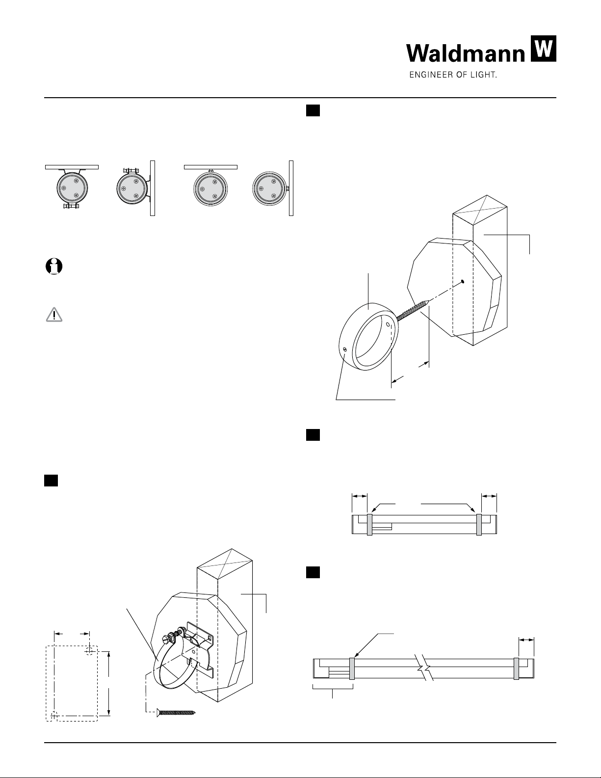
Ceiling Wall Ceiling Wall
Surface Strap Bracket Surface Ring Bracket
Important note!
Please make sure to observe the safety instructions and
warnings given in the operating instructions of the luminaire.
Safety Instructions
Mount the luminaire indoor or outdoor in wet or dry locations,
not subject to explosion hazards!
Mount the luminaire only to a suitable ceiling or wall surface
using appropriate screws or fasteners.
Mounting and connection of the luminaire must be carried out
by a qualified electrician and must be wired in accordance
with the National Electrical Code and applicable local codes.
Proper grounding is required for safety.
Warning: Make certain power is OFF before installing or
maintaining the luminaire.
B Surface Ring Bracket Mounting
The Surface Ring Bracket must be securely mounted to
the ceiling or wall. It is recommended that the bracket(s) be
mounted directly to a wood structural member. It is the duty
of the installer to be sure the fixture is securely mounted to the
ceiling or wall surface using an appropriately sized wall plug if
a wood substrate is not available.
Typical Installation
Surface Ring Bracket
1-3/4”
Tighten plastic set screw after luminaire
has been installed to prevent rotation.
Wood
structural
member
C Bracket Spacing
The Surface Strap Bracket or Surface Ring Bracket should
be placed 3 to 6 inches from each end of the luminaire.
A Surface Strap Bracket Mounting
0˝–6˝ 0˝–6˝
The Surface Strap Bracket must be securely mounted to the
ceiling or wall surface. It is recommended that the bracket(s)
be mounted directly to a wood structural member. It is the
duty of the installer to be sure the fixture is securely
mounted to the ceiling or wall surface
using appropriate fasteners.
Typical Installation
D Alternate Bracket Spacing for Luminaires
For luminaires with ballast compartment at end of luminaire,
Surface Strap Bracket
place one bracket near the end of the ballast compartment as
shown below.
Wood
1-3/16”
2-3/16”
Mounting Holes
Page 1 of 2 Note: Technical specifications are subject to changes. ® 2012
Wood screw
recommended
structural
member
Ballast compartment
Bracket
Place bracket near end
of ballast compartment
0˝–6˝
RL70 SERIES MOUNTING
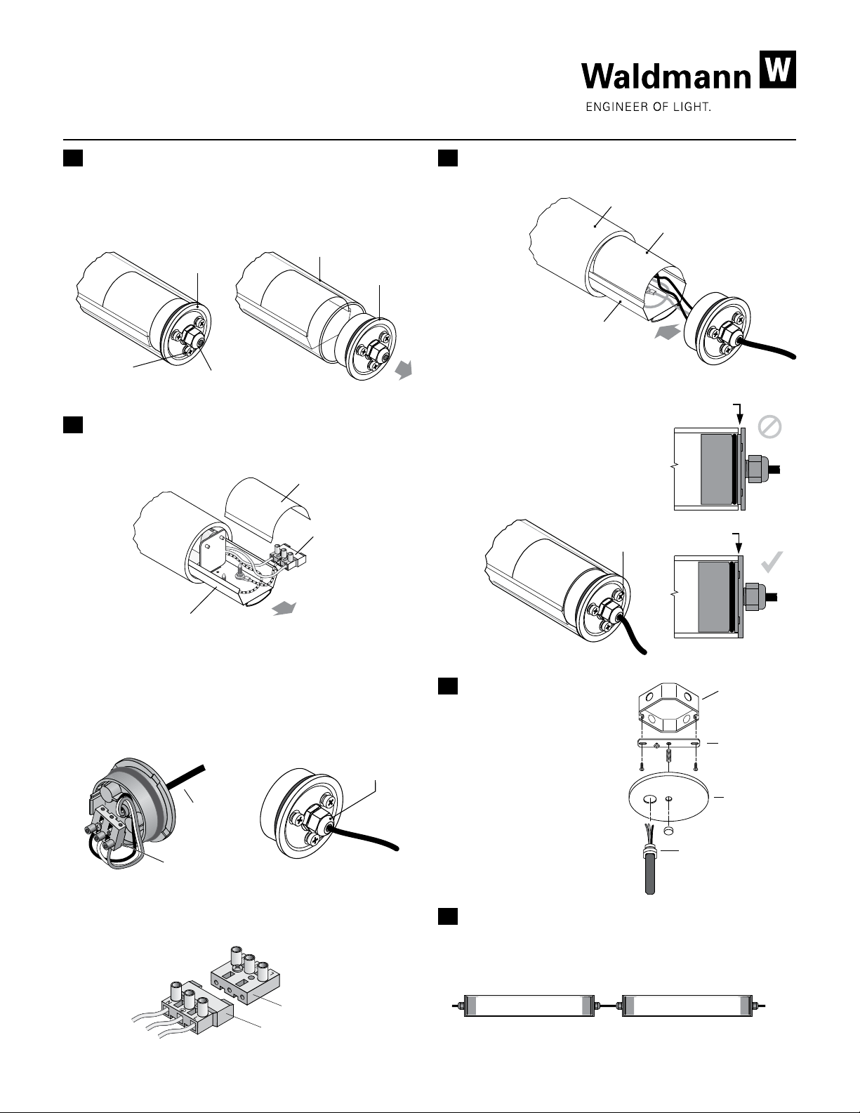
Replace
cover
Slide wireway
into tube
Tighten
screws
Tube
Tighten
screws
Surface Mounting Instructions For RL70 Luminaire
E Removing the End Cap
Loosen all three phillips head screws that attach the End Cap
just to the point where the heads are out past the End Cap.
Remove the End Cap with inner piece and O-ring attached.
Tube
Remove
end cap
Loosen
screws
End cap
Connector
F Wiring the RL70 Luminaire
1. Slide wireway out of tube and remove cover.
Remove cover
Socket
G Reassemble the Luminaire
1. Replace the inner cover and slide wireway back into
tube with
end cap
attached.
Gap!
2. Insert the end cap into the end
of the tube. Tighten all three, (3)
phillips head screws to seal end
cap. Make sure the end cap fits
properly. Align wireway so there
is no gap between the tube and
end cap.
No Gap!
Slide out wireway
2. Insert electric cable through connector in end cap. Cable
diameter to be .340” diameter, 3-conductor. Attach hot,
neutral, and ground wires to socket. Observe labeling at
the socket strip. Be sure to tighten the connector nut.
Tighten
connector nut
Electric
feed cable
.340” Diam.
Socket
3. Attach plug from luminaire to socket on end cap.
End cap socket
Luminaire plug
H Canopy Kit (Optional)
Electrical
box (by others)
An optional canopy
kit can be ordered for
connection of the RL70
Mounting
strap
luminaire to the existing
electrical junction box.
The canopy kit can be
used for ceiling or wall
Canopy with
cap nut
mounted luminaires.
Strain relief
bushing
I Tandem/Continuous Mounting for the RL70
A separate data sheet is available which covers the
requirements for continuous wiring of the RL70 luminaires.
Consult factory for further information.
Page 2 of 2 Note: Technical specifications are subject to changes. ® 2012
 Loading...