


VT24 USER MANUAL(EN)
4 Wire Video Intercom System
TALK
Read this manual carefully before using the product, and keep it well for future use.
-1-
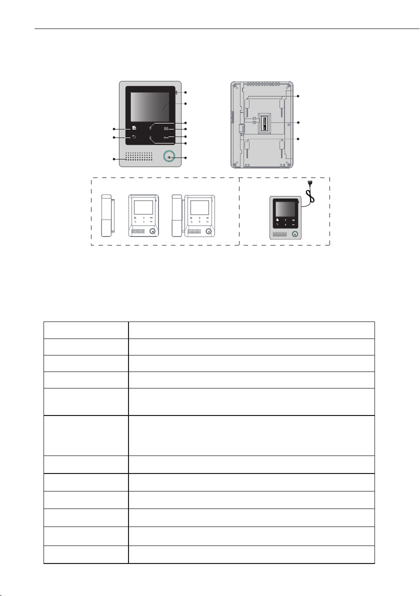
1. Parts and Functions
Microphone
LCD Screen
PP+
JS/PS
1R
2W
3Y
4B
JS/OS1
JVDJS/AP
4B
2W
12V
TALK
TALK
Up Button
Memo Button
UNLOCK Button
Down Button
TALK Button
TALK
MENU Button
Cancel Button
Speaker
Note 1 Note 2
+ =
TALK
Note:1.Both hands free and handset communication are available.
2.Built-in power supply is optional .
Key functions
LCD screen Display the visitors' image
Unlock button Press to release the door
Up button Press to move up or increase the value
Down button Press to move down or decrease the value
Memo button
Talk button
Menu button Press twice to open the menu shortcuts.
Press to view the recorded pictures(must connect MEM)
Blink when receiving new recorded pictures
Press to communicate hands free with visitor
Press to view the outdoor condition in standby mode
LED will blink when receiving calling
Mounting Hook
connection port
Mounting Hook
Cancel button Press to cancel the operation
Microphone Receive voice from the user
Mounting hook Use to hang up the monitor
Connection port Bus terminal
Speaker Send out vioce from the visitor

2. Monitor Mounting
145~160 cm
Accessory ttings:
1) Mounting Bracket and special 4 core wire
2) Two screws of 4X25 are used to fasten the Mounting Bracket on the wall.
Installation steps:
■ Installation Height for indoor monitor usually is 145- 160CM (refer to sketch map)
■ Attach the screws to the wall to x the mounting bracket.
■ Refer to the system connection section of this manual, connect wires correctly.
■ Hang the monitor rmly on the bracket.
-2-
3. About Main Menu
The Main Menu is your starting point for using all the applications on your monitor.
To open the Main Menu page, tap" Menu" key,a full calendar will be shown on
screen,tap" Menu" key again,main menu will be displayed.
Current date
2011- 09
1 2 3
4 5 6 7 8 9 10
11 12 13 14 15 16 17
18 19 20
25
26
27
21
28
21/09/2011 14:37
Current date
Note:1. Press / button to view last/next calendar
2." " this icon will be shown when the staircase light item is set to 1 or 2(refer to part 9->staircase light). If the icon " " transform
to (should connect RLC).It means that the staircase light lights on,press
:This icon will be displayed when the recorded pictures have not been viewed,pressing on monitor can see the recorded pictures.
Current time
22
29
23 24
30
Unlock
button to turn off the light.

-3-
4. System Wiring
Terminal Discription
JSB
4BS
4BS1
Jumper
SB_DET
CH_DET
GD
GD
12PS
PP+
JS/PS
1R
2W
3Y
4B
JS/OS1
JVDJS/AP
4B
2W
12V
1) JS/PS:Power supply connection port.(for built-in power supply model,this terminal
is not included.)
2) JVD:JVD is used for setting the video impedance. If only one monitor is installed,
keep the jumper. If multi Monitors are installed, be sure of taking away all JVD of
Monitors except the last one.
3) JS/AP:Audio phone connection port(VT672)
4) JS/OS1:The door station connection port
5) JSB:Addtional handset connection port(should take off the jumper)
JS/PS
JS/OS1
JVDJS/AP
PP+
1R
2W
3Y
4B
4B
2W
12V
Basic Connection
Door station
Red
Black
White
Yellow
1R2W3Y
4B
Red
White
1R2W3Y
AC ~
TALK
PP+
JS/PS
1R
2W
3Y
Reserve
4B
JS/OS1
Black
Yellow
4B
JVDJS/AP
4B
2W
12V
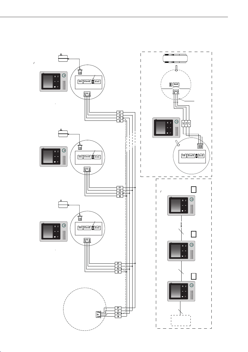
Extending Monitors
AC ~
User code=N(N<5)
Back View
AC ~
Reserve!
P+1R2W3Y4B2W12V
P-
JS/PS
JS/OS1
-4-
4B
JVDJS/AP
2W
4B
+12
JS-LK
JS-AP
INSIDE
GX-3P
(90 Degree ROTATE)
Red
Black
White
TALK
Red
Black
White
User code=2
User code=1
P-
Back View
Removed!
P+1R2W3Y4B2W12V
4B
JS/PS
JVDJS/AP
JS/OS1
P-
Back View
P+1R2W3Y4B2W12V
4B
JS/PS
JVDJS/AP
JS/OS1
Extending Audio Phone:
PS
TALKTALKTALK
AC ~
Removed!
TALK TALK TALK
JS/PS
JVDJS/AP
JS/OS1
Back View
Black
Yellow
White
Red
P+1R2W3Y4B2W12V
4B
P-
Door station
Monitor
N#
User code=N(N<5)
Monitor
User code=2
2#
Monitor
User code=1
1#
Camera
JVD Reserved
PSPS
JVD Removed!JVD Removed!
4 4
4

-5-
Extending Multi Monitors with BDU
AC ~
User code=1
AC ~
JVD Reserved
TALK
JVD Reserved
TALK
AC ~
JVD Reserved
TALK
User code=2
User code=N(N<5)
VT-BDU
4B3Y
4B3Y
4B3Y
4B3Y
2W
2W
2W
2W
JW/OS
JW/VP1
JW/VP2
JW/VP3
1R
1R
1R
1R
VT-BDU
150R
75R
SET-3Y
HI
SET-3Y
4
About the BDU instructions ,please refer to BDU user manual for more detail informations.
Door station

Extending Multi Door Stations with MDS
P-
TALKTALK
User code=N(N<5)
P+
JS/PS
1R
2W
3Y
4B
JS/OS1
JVDJS/AP
4B
2W
12V
-6-
1R
Red
2W
White
3Y
Yellow
4B
Black
User code=1
JS/PS
JS/OS1
JVDJS/AP
Remove Reserve
PP+
1R
2W
3Y
4B
4B
2W
12V
1R
Red
2W
White
3Y
Yellow
4B
Black
1R
Red
2W
White
3Y
Yellow
4B
Black
JW_VP
SET
DS4
DS2
DS3
DS1
JW_VP
About the MDS instructions ,please refer to MDS user manual for more detail informations.
4#
3#
2#
1#

DS1 00:30
-7-
5. Basic Door Release Operation
Answering a Door Call
1. Press the CALL button on door station.
2. The monitor rings,and the visitor's image will be seen on screen.
Note:the screen turns off after 40 seconds if nobody answers.
3. Press TALK Button on monitor(the LED will transform to red color), you can
communicate hands free(if the monitor takes with handset,pick up handset to talk)
with the visitor for 90 seconds.After nishing communication,press TALK button
again to end the communication.If the system connects two or more Monitors, pick
up any Monitor, the others will be automatically shut off.
Status bar
1 2
4
3
► 1.show the current door station for monitoring.
► 2.show the waiting time for calling.
► 3.if the monitor is set to silence mode,this icon
will be shown.
► 4.if the system connect VT-RLC module which
control light,and the Staircase Light item is set
to 1or 2 (refer to part 9->>Staircase Light),this
icon will be shown when receive calling.
Door Release
During talking or monitoring state, Press Unlock Button to release the door for the
visitor.
Entrance Monitoring
When the monitor is in standby mode, press TALK Button, The screen can display
the view of outside. If multi door stations are installed,press TALK Button,then
touch Cancel button (or select Monitor item on main menu page) to get into the
camera switch mode. Select DS 1/2/3/4 to monitor the door station or CCTV camera
you want.See the following diagrams.

-8-
6. Intercom Function
Intercom function can be initiated by any Monitor when multi monitors are installed.
Intercom: Select Intercom item on main menu on any monitor to enter intercom
page, see the diagram on right.select one of user,then press Menu button to call.If
the selected monitor answers the call,intercom talking is strating.("!"means the current
operating monitor)
!
Inner Call: Select Inner Call item on main menu on any monitor to enter intercom
page, see the diagram on right.All monitors will ring at the same time,whichever
monitor answers the call, conversation is starting.and the other monitors will stop
ringing .
2 1
User 1 calling user 2

-9-
7. Public Memory Sharing(Optional)
To perform memory sharing function ,the system must connect VT-MEM module.
Public memory sharing means that all monitors can view the recorded pictures which is
saved in VT-MEM unit.(about VT-MEM module instructions, plaese refer to VT-MEM
user manual for more detail information)
For each time calling,the system will record one image automatically.
To view the recorded pictures,tap Memo button. If the system receives new recorded
pictures,the Memo button will blink all the time until the pictures have been viewed.
Press / button to view last/next picture.
Wiring Diagram for Public Memory Sharing
User code=1 User code=2 User code=N(N<5)
VT-MEM
PS12V
JVD Reserve JVD Remove JVD Reserved
444 4
TALK TALK TALK
8. Basic Setup Instructions
Ring Tone Settings
Select Tools item on main menu page,then select User Setup->>Call Tone->> DS Call
Tone or Intercom Call Tone, There are 12 pieces ring tones can be selected.Select a
ring tone you want, then touch Menu button to save and return last page.but if you
don't want to save the settings, touch
DS Call Tone
Intercom Call Tone
:set the ring tone calling from outdoor station.
:set the ring tone calling from intercom call or inner call.
button to exit.

Ring Volume and Night Ring Volume Setting
You can set a ring volume for day time and
night time individually, 06:00 AM~18:00
PM is the day time by default, but the
day time can be modified at any time by
yourself(refer to Day time setting section
for more detail information).
Select Tools item on main menu page,then
select User Setup->>Call Tone->> Ring
Volume or Night Ring Volume to set a
appropriate value.if you don't want to be
disturbed at night,you can set the night ring
volume to 0.
Date and Time Setting
Th ere are 2 formats for dat e an d ti me
display, Select Tools -> > U ser Setup>>Date And Time->>Calendar. Set the
date and time by touching / button
to increse/decrese the value,use button
to select the setting item.(note:you can set
the date and time format at Tools ->> User
Setup->>Date And Time->>Date Format/
Time Format page)
2011-09-15 14:00
-10-
6
Day Time Setting
The day time setting is used to distinguish the
day ring volume and night ring volume.06:00
AM~18:00 PM is the default day time .Select
Tools ->> User Setup->>Date And Time>>Day Time.Please refer to the operation
instructions below the menu for more detail.
06:00 ~ 18:00

-11-
Monitor Time Setting
Select Tools item on main menu page,then
se lect User Setu p ->> Monit or Time .
Modify the value by touching / button
to increse/decrese the value,use button
to select the setting item.
Restore to Default
6
01 30
Select Tools ->> User Setup->>
the restore operation. press Menu button to conrm,All settings will be restored to
default except Calendar item.
Restore to default
,a message will be asked to conrm
Screen Setting
During monitoring or talking state, press
Menu button,the Adjust menu page will be
displayed.
The rst item is Scene mode selection: Total
4 screen modes can be selected in sequence:
Normal, User, Soft and Bright.
The Brightness and Color item is for the
image quality setting.
The Talk Volume item is for talking volume
adjustment.
5

-12-
9. Monitor Parameter Setting
Select Tools ->> Installer Setup(1)/Installer Setup(2), total 8 setting items will be
displayed on screen. Just input the value to modify the setting.
Item Description
Used to set the monitor code,[1]:master monitor;[2]
User Code
the first slave monitor;[3]the second slave
monitor;[4]the third slave monitor;[5] the fouth
slave monitor
Language Select
To standard model,support one language only,but
you can customize two languages.
Unlock Timing Range from 1~9s
Unlock Auto Off
Range from 0~9s,the monitor will be closed in
setting time after releasing the door.
Used to add the remote controller or delete remote
Remote Setup
controller,[0]:delete remote control;[1]:add remote
control.
Whe n the system is c onnect ed RLC modul e
controlling staircase light,the status for staircase
light can be set.[0]: disable at any time when
Staircase Light
receive calling;[1]:light on at night only when
receive calling;[2]light on at any time when receive
calling.Note that this item should be set on master
monitor(user code=1),for slave monitors,this item
is invalid.
Default
value
1
one
3s
0
0
0(disable)
Online Search... Search the devices connected to the system
Restore parameter settings to default value,select
Recover Settings...
Recover Settings
recover all settings" will be asked,press Menu
button to conrm,restore setting will be performed
,an information of "Are you sure to
immediately. Please note that the recover settings
will not change user code item.
_
_

-13-
10. Specication
●Power Supply: DC16-24V
●Power Supply for built-in SMPS: AC110~~230V
●Power Consumption: standby 1.2W,working 8W
●Monitor Screen: 4 inch digital TFT
●Display Resolution: 320(RGB)*240 pixels
●Built-in Memory for MEM: 120 MB
●Picture Memo: 800pcs(inner memory),
●Wiring: 4 wires, polarity
●Monitor time: 40 seconds
●Talking time: 90 seconds
●Dimensions: 186(H)X133(W)X30(D)mm

Note:

The design and specications can be modied without notice to the user. Right to interpret and copyright of this manual are preserved.
Printed In China / 2011. 09
 Loading...