

Page 1

Electronic Emission Notices
Federal Communications Commission (FCC) Statement
This equipment has been tested and found to comply with the limits for a Class B digital
device, pursuant to Part 15 of FCC Rules. These limits are designed to provide reasonable
protection against harmful interference in a residential installation. This equipment
generates, uses and can radiate radio frequency energy and, if not installed and used in
accordance with instructions contained in this manual, may cause harmful interference
to radio and television communications. However, there is no guarantee that interference
will not occur in a particular installation.
If this equipment does cause harmful interference to radio or television reception, which
can be determined by turning the equipment off and on, the user is encouraged to try to
correct the interference by one or more of the following measures:
- REORIENT OR RELOCATE THE RECEIVING ANTENNA
- INCREASE THE SEPARATION BETWEEN THE EQUIPMENT AND THE RECEIVER
- CONNECT THE EQUIPMENT INTO AN OUTLET ON A CIRCUIT DIFFERENT FROM
THAT OF THE RECEIVER
- CONSULT THE DEALER OR AN EXPERIENCED AUDIO/TELEVISION TECHNICIAN
NOTE: Connecting this device to peripheral devices that do not comply with Class B
requirements, or using an unshielded peripheral data cable, could also result in
harmful interference to radio or television reception.
The user is cautioned that any changes or modifications not expressly approved
by the party responsible for compliance could void the users authority to operate
this equipment.
To ensure that the use of this product does not contribute to interference, it is
necessary to use shielded I/O cables.
Copyright
This manual is copyrighted with all rights reserved. No portion of this manual may be
copied or reproduced by any means.
While every precaution has been taken in the preparation of this manual, no responsibility
for errors or omissions is assumed. Neither is any liability assumed for damages resulting
from the use of the information contained herein.
Trademarks
All brand names, logos and registered trademarks mentioned are property of their
respective owners.
Page 2

Technical Reference Booklet
TABLE OF CONTENTS
HARDWARE CONFIGURATION .................................................................... 4
Key Features.................................................................................................. 4
MOTHERBOARD LAYOUT ............................................................................ 7
REAR PANEL ................................................................................................ 9
AUDIO CONFIGURATION .............................................................................. 12
SPEAKER CONFIGURATION ........................................................................ 12
Method 1: Using the 4/6 surround audio output of the
back panel only ...................................................................................... 12
Method 2: Using S-Bracket connectors ................................................. 14
CONNECTORS ............................................................................................. 16
Floppy Disk Drive Connector - CN3 ...................................................... 16
Hard Disk Connectors - CN1 ................................................................ 16
S-Bracket (SPDIF) /CEN/LFE/Surround Output Connector -
J19 for AC97 only (optional) ............................................................................... 17
SPDIF Header - J29 for HD Audio (optional) ........................................ 18
Fan Power Connectors - CPUFAN/SYSFAN (optional) ........................ 19
CD-IN Connector - J30 (optional) .......................................................... 20
Power LED - D64, D65 (optional)..................................................................20
Serial ATA Hard Disk Connectors -
SATA-1/SATA-2/SATA-3/SATA-4 (optional) ............................................... 21
Front Panel Audio Header - FP-S1 ........................................................ 23
IEEE 1394 Connector:CN9/CN10 (optional)...............................................24
USB Connectors - FP-U1/FP-U2 (optional) .......................................... 25
Front Panel Header - FP1 ...................................................................... 26
JUMPER SETTING ....................................................................................... 27
CMOS Clear - JP1 .................................................................................. 27
SLOTS ......................................................................................................... 28
CPU INSTALLATION .................................................................................... 29
INSTALL DDRII DIMMS ............................................................................... 32
Page 3

!
CrossFire Setup .......................................................................................... 33
Installing Driver ...................................................................................... 33
BIOS SETUP ................................................................................................ 35
About the Setup Utility ............................................................................ 35
The Standard Configuration .................................................................. 35
Entering the Setup Utility ........................................................................ 35
Main Menu .............................................................................................. 36
Standard CMOS Features ................................................................ 37
Advanced BIOS Features.................................................................. 38
Advanced Chipset Features ............................................................. 38
Integrated Peripherals ...................................................................... 38
Power Management Setup ............................................................... 38
PNP/PCI Configurations ................................................................... 38
PC Health Status .............................................................................. 38
Frequency/Voltage Control ............................................................... 38
Set Supervisor/User Password ........................................................ 39
Save & Exit Setup .............................................................................. 39
Exit Without Saving ........................................................................... 39
Flash Update Procedure .................................................................. 40
REALTEK HD AUDIO DRIVER SETUP ........................................................... 41
Getting Started..................................................................................................4 1
Sound Effect ........................................................................................... 41
Environment Simulation ........................................................................ 41
Equalizer Selection ................................................................................ 42
Frequently Used Equalizer Setting ........................................................ 42
Karaoke Mode ........................................................................................ 42
Mixer ....................................................................................................... 43
Playback control ............................................................................... 43
Recording control ............................................................................. 44
Audio I/O ........................................................................................... 45
Speaker Configuration ..................................................................... 46
Global Connector Settings............................................................... 47
S/PDIF .............................................................................................. 48
Speaker Calibration ......................................................................... 48
Microphone....................................................................................... 49
Noise Suppression.......................................................................... 49
Beam Forming ................................................................................. 49
Acoustic Echo Cancellation ............................................................. 49
Audio Demo ..................................................................................... 50
Information ....................................................................................... 50
APPENDIX .................................................................................................... 51
......
Page 4

"
Technical Reference Booklet
HARDWARE CONFIGURATION
Key Features :
Chipset
Intel® 945P/945PL Chipset.
Processor
Supports Intel® Celeron® , Pentium® 4, Pentium® D, CoreTM 2 Duo
processors in the LGA775 -pin package (with 0.8V~1.6V voltage).
Supports 64-bit PSB (Processor System Bus) frequency of 533MHz/
800MHz (133MHz/200MHz bus clock).
Supports Hyper-Threading Technology.
Supports 64bit PSB frequency of 1066MHz (266MHz bus clock) (only for
945P).
VRD 11.0 (Voltage Regulator Modules) Onboard
Flexible motherboard design with onboard VRD11.0, easy to upgrade
with future Intel® Celeron, Pentium® 4, Pentium® D, CoreTM 2 Duo
processors.
0.03125V to 1.600V in 6.25mV steps for VRM11.0.
System Memory
A total of two 240 pin DDRII SDRAM sockets.
Dual-channel (128 bits wide) DDRII memory interface.
Supports 128Mb, 256Mb, 512Mb,1G technologies implemented
as X8, X16 devices.
Supports DDRII533.
Supports DDRII667 (only for 945P).
Support for Non-ECC memory only.
Maximum memory size: 4GB.
Onboard I/O
_ One onboard PCI fast IDE port supporting up to 2 ATA, ATA2 , Ultra
ATA33/66/100 IDE HDDs, CD-ROMs, ZIP drives and LS-120 drives
as boot drive.
_ One ECP/EPP parallel port.
_ One floppy port which supports two FDD of 1.44MB, 2.88MB capacity.
_ Six/eight USB ports.
_ PS/2 keyboard support.
_ PS/2 mouse support.
_ One Front Panel Sound Connector.
_ Infrared (IrDA) support via a header.
Two 16550 Compatible UART serial port.
Page 5

#
Plug-and-Play
Supports Plug and Play specification 1.1.
Plug and Play for Windows®2000 as well as Windows®XP.
Fully steerable PCI interrupts.
Onboard Realtek RT8100C/RT8110S LAN (optional)
Integrated 10/100/1000 (only RT8110S LAN) transceiver.
Supports Full Duplex flow control (IEEE802.3x)
Fully compliant with IEEE802.3, IEEE802.3u, IEEE802.3ab.
Transmit/Receive FIFO (8K/64K) support.
PCI Express Graphics interface (optional)
_ One 16-lane (X16 port) PCI Express graphics port, fully compliant
with the PCI Express Base Specification revision 1.0a.
_ A base PCI Express frequency of 2.5GB/s only.
_ PCI Express support and Enhanced Addressing Mechanism.
Onboard AC97 Sound (optional)
Integrated AC97 controller with standard AC97 Codec.
Direct Sound and Sound Blaster compatible.
Full-Duplex 16-bit record and play back.
PnP and APM 1.2 support.
Windows® 2000/XP ready.
Line-in, Line-out, Mic-in.
Supports AC97 codes for six sound channel output.
Onboard IEEE1394 (optional)
Compliant with 1394 OHCI specifications v1.0 and v1.1.
Integrated 400Mbit 2 port PHY.
System BIOS
PnP, APM, ATAPI for Windows® 2000/XP.
Full support of ACPI & DMI.
Auto detects and supports LBA harddisks with capacities over 160GB.
Easy to upgrade BIOS by end-user.
Onboard HD Audio Sound (optional)
Integrated Realtek HD Audio controller.
Full Direct Sound and Sound Blaster compatible.
Full-Duplex 4 24-bit two-channel DACs and 3 stereo 20-bit ADCs.
PnP and APM 1.2 support.
Windows® 2000/XP ready.
Line-in, Line-out, Mic-in, SPDIF-in, SPDIF-out.
Supports HD Audio codec for eight channel sound output.
Page 6
$
Technical Reference Booklet
Static electricity can harm delicate components of the motherboard.
To prevent damage caused by static electricity, discharge the static
electricity from your body before you touch any of the computers
electronic components.
Expanded USB Support
Includes 4 UHCI host controllers, increasing the number of external
ports to eight.
Includes 1 EHCI USB2.0 Host Controller that supports all six/eight ports
(Bandwidth shared between the eight ports).
Power Management
Supports SMM, APM and ACPI.
Break switch for instant suspend/resume on system operations.
Energy star Green PC compliant.
Hardware monitoring circuit provides voltage, temperature, fan speed,
etc. monitoring (optional).
Supports suspend-to-RAM (STR) (optional).
External Modem Ring-in Wake-up support.
Integrated Serial ATA host Controller
Independent DMA operation on four ports (optional).
Data transfer rates of 300Mb/s.
RAID feature support (optional).
Expansion Slots
1 PCI Express X16 slot.
_ 1 PCI Express X4 slots (Support PCI Express VGA card).
_ 3 PCI bus slots - ver. 2.1 compliant (optional).
Page 7
%
NOTE :
1) Be sure to check the HDD cable orientation in order to match the colored strip to the pin 1 end
of the connector.
2) When you start up the system, please wait for 5 seconds after you power on AC.
3) Adding a metal spaced plate to the back of the Socket 775 is not recommended as this will short
motherboard components and damage the system.
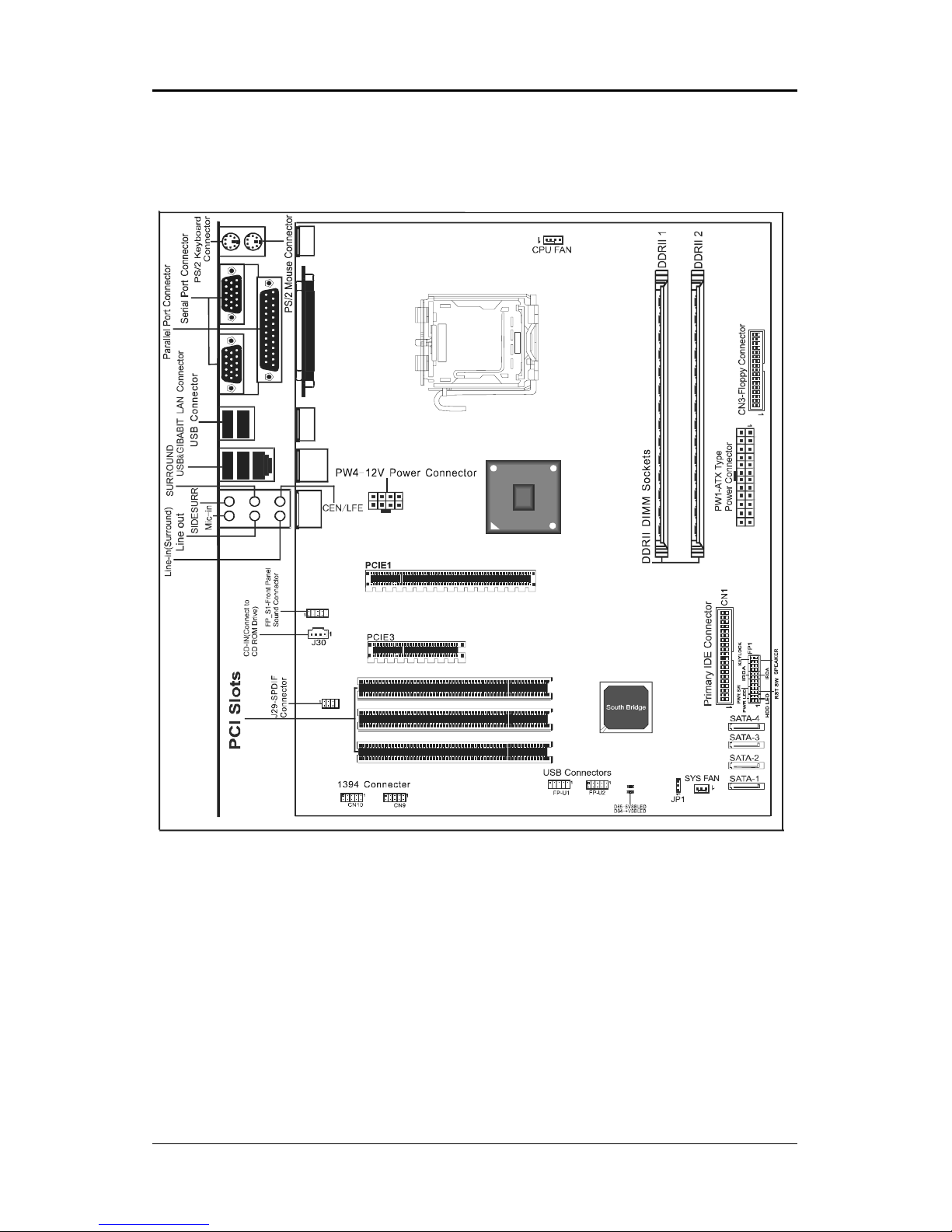
MOTHERBOARD LAYOUT (for HD Audio only)
The following diagram shows the relative positions of the jumpers, connectors,
major components and memory banks on the motherboard.
PKE;;9$Wsgo ix
J
S
\
G
S
R
R
V
I
Q
S
Z
I
Page 8
&
Technical Reference Booklet
NOTE :
1) Be sure to check the HDD cable orientation in order to match the colored strip to the pin 1 end
of the connector.
2) When you start up the system, please wait for 5 seconds after you power on AC.
3) Adding a metal spaced plate to the back of the Socket 775 is not recommended as this will short
motherboard components and damage the system.
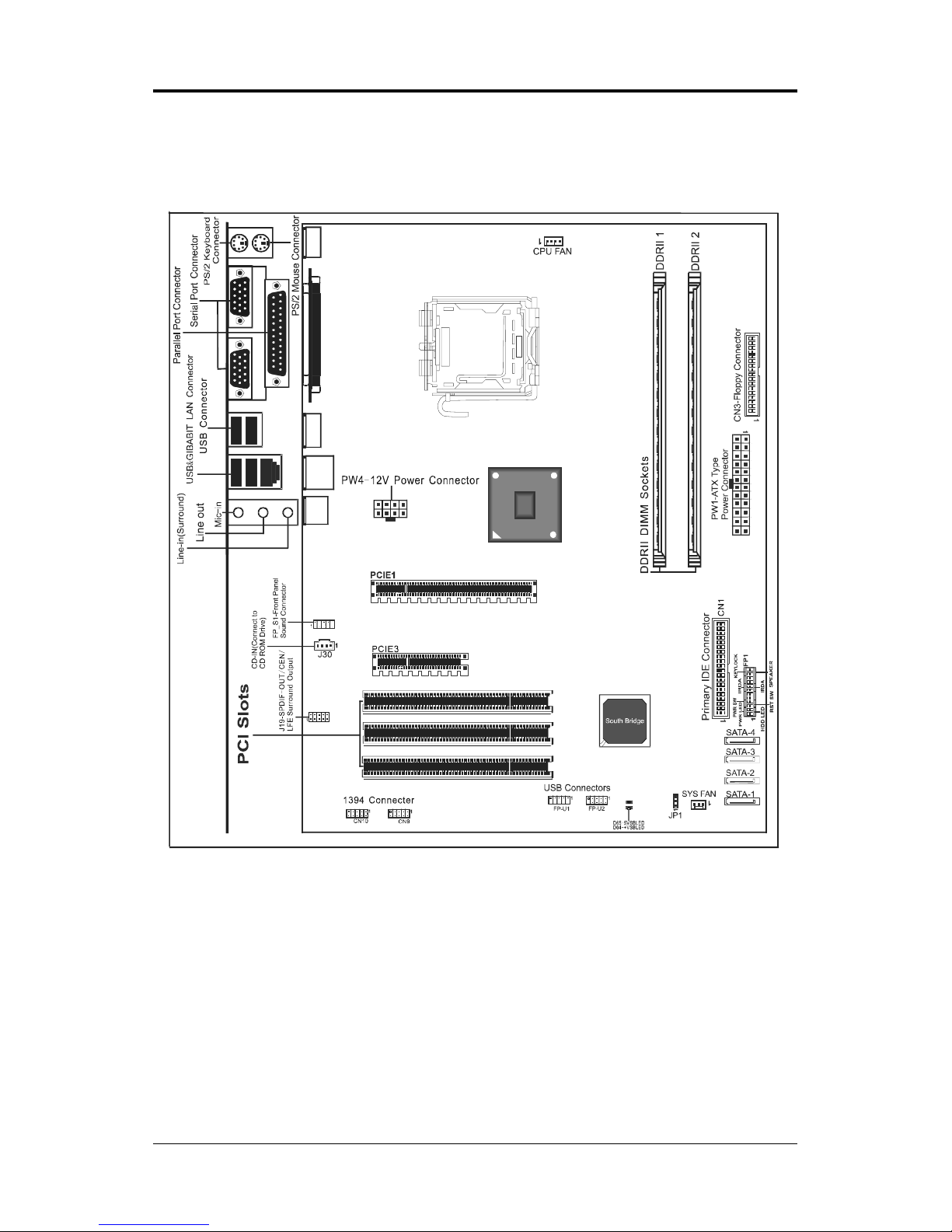
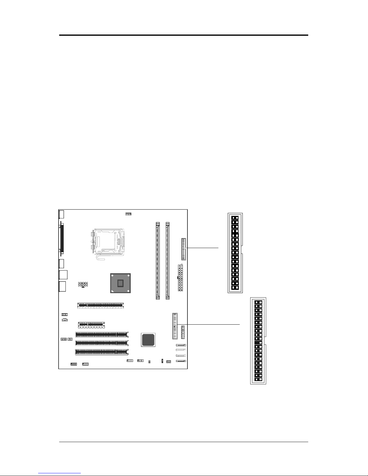
MOTHERBOARD LAYOUT (for AC97 Sound only)
The following diagram shows the relative positions of the jumpers, connectors,
major components and memory banks on the motherboard.
PKE;;9$Wsgoix
J
S
\
G
S
R
R
V
I
Q
S
Z
I
Page 9
'
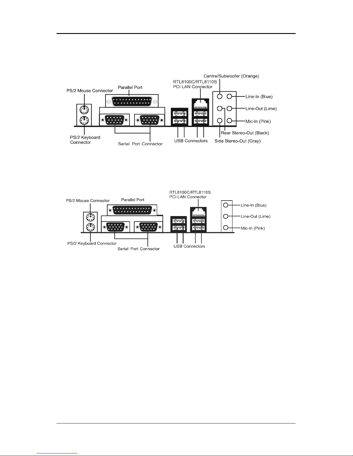
REAR PANEL
The back panel (for HD Audio) provides the following connectors:
The back panel (for AC97 Audio) provides the following connectors:
Page 10
Technical Reference Booklet
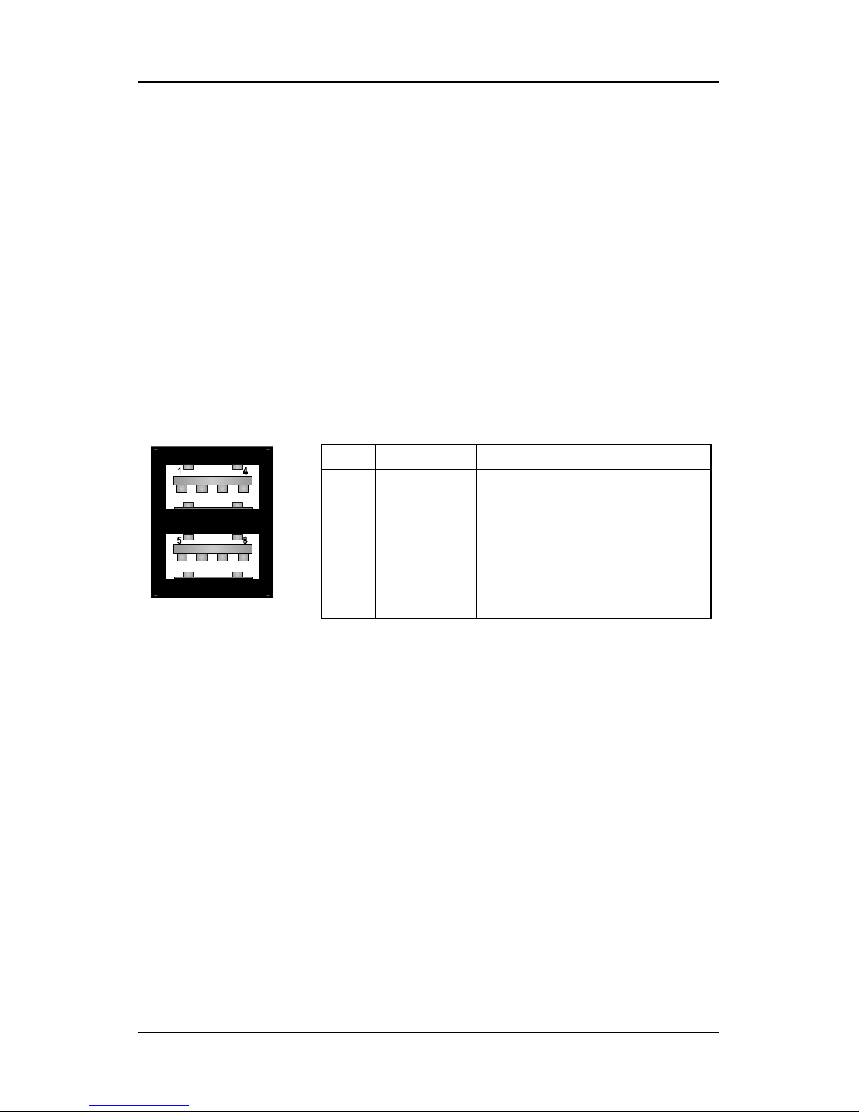
PIN SIGNAL DESCRIPTION
1 VCC +5V/5VSB (optional)
2 -Data 0 Negative Data Channel 0
3 +Data0 Positive Data Channel 0
4 GND Ground
5 VCC +5V/5VSB (optional)
6 -Data 1 Negative Data Channel 1
7 +Data 1 Positive Data Channel 1
8 GND Ground
Mouse Connector
The motherboard provides a standard PS/2
®
mouse mini DIN connector for
attaching a PS/2
®
mouse. You can plug a PS/2® mouse directly into this
connector.
Keyboard Connector
The motherboard provides a standard PS/2
®
keyboard mini DIN connector for
attaching a PS/2
®
keyboard. You can plug a PS/2® keyboard directly into this
connector.
USB 2.0 Connector
The motherboard provides a UHCI (Universal Host Controller Interface)
Universal Serial Bus root for attaching USB devices such as keyboard, mouse
or other USB-compatible devices. You can plug the USB device directly into the
connector.
USB 2.0 Connector DescriptionUSB 2.0 Connector
Page 11

Serial Port Connector: COM1/COM2
The Ports are 16550A high speed communication ports that send/receive
16bytes FIFOs. You can attach a serial mouse or other serial devices directly to
the connectors.
Video Out Connector (Optional)
The motherboard provides a Video out port to connect a 15-pin analog video
monitor.
Parallel Port Connector:LPT1
The motherboard provides a 25-pin female centronic connector as LPT. A
parallel port is a standard printer port that supports Enhanced Parallel Port
(EPP) and Extended Capabilities Parallel Port (ECP) mode.
LAN Jack Connector (Optional)
The motherboard provides one standard RJ-45 jack for connecting to a Local
Area Network (LAN). You can connect the network cable to the LAN jack.
8 Channel HD Audio
Option select of 2, 6, or 8 channel audio from onboard High Definition audio
compliant CODEC with 20-bit ADC and 24-bit DAC resolution.
- Support CD-In, SPDIF-in and SPDIF-out.
- Optical & Coaxial SPDIF-out available on rear panel.
- Support jack detection for easy audio device installation.
Rear panel audio jacks configuration:
Audio Jack Color 2 Channel 6 Channel 8 Channel
Blue Line-In Line-In Line-In
Lime Line-Out Front Stereo-Out Front Stereo-Out
Pink Mic-In Mic-In Mic-In
Gray -- -- Side Stereo-Out
Black -- Rear Stereo-Out Rear Stereo-Out
Orange -- Centre & Subwoofer Centre & Subwoofer
Page 12
Technical Reference Booklet
AUDIO CONFIGURATION (for AC97 Sound only)
After installing the audio driver, you can select 2/4/6 channel surround audio
output in the software utility and then connect surround speakers to appropriate
audio ports.
There are two ways to obtain 4/6 channel surround audio output:
1. Using the 4/6 surround audio output of the back panel only. All surround
speakers connect to this audio connector.
2. Using the S-Bracket (optional cable). You have install the S-Bracket into the
computer. Connect two front speakers to back panels Line Out port, and
the rest of speakers to S-Bracket.
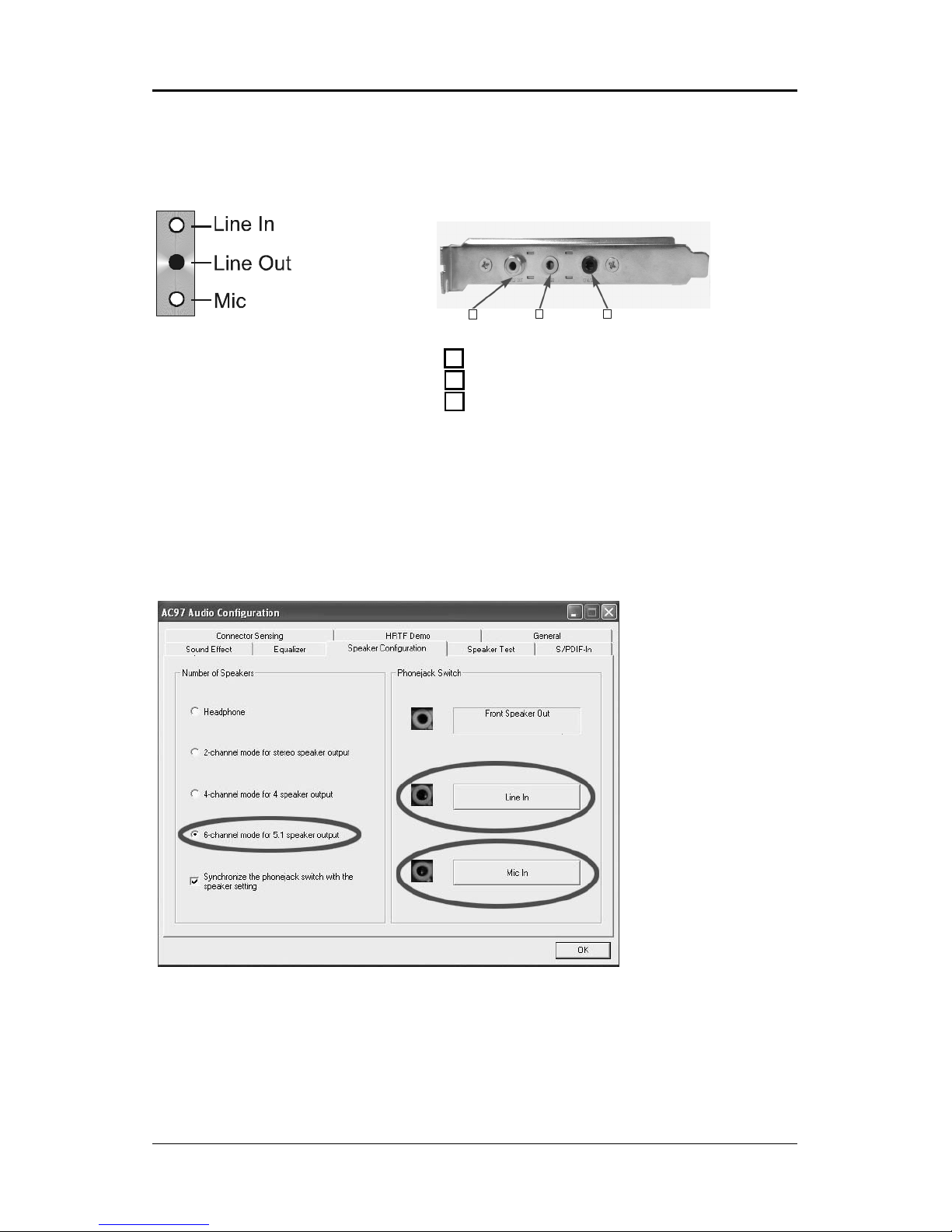
SPEAKER CONFIGURATION
Method 1:
Using the 4/6 surround audio output of the back panel only
After installing the audio drivers, you can attach the speakers for 2-/4-/6- channel
audio output. Please connect the speakers to the LINE OUT connectors.
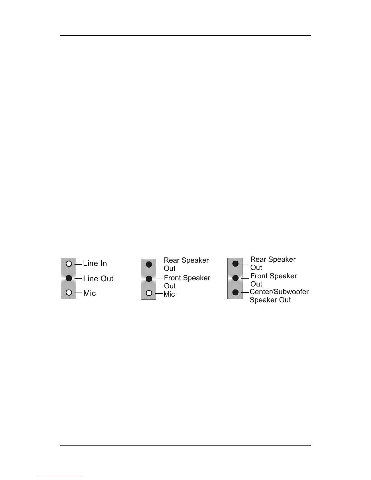
Different connector configurations for 2-/4-/6-channel options are listed below:
2-Channel
In 2-channel
configuration, Line
Out, Line In and MIC
functions all exist.
4-Channel
When set to 4-channel
configuration, Line In
is replaced by Rear
Speaker Out. The Line
in function does not
exist.
6-Channel
When set to 6-channel
configuration, Line In is
replaced by Rear
Speaker Out. Mic is
replaced by Center/
Subwoofer Speaker Out.
Line in and Mic functions
do not exist.
Page 13
!
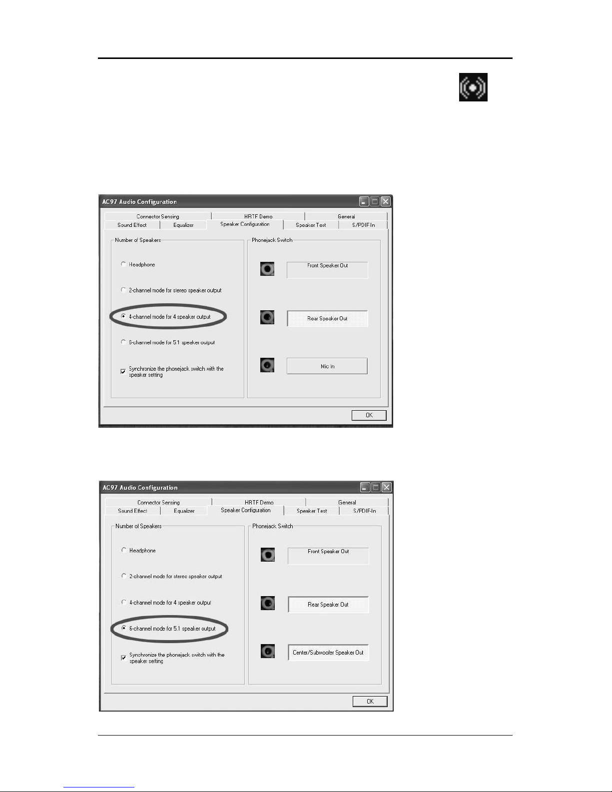
In the software utility, double click the AC97 Audio configuration icon from
the window tray on the right bottom.
The AC97 Audio Configuration box will appear. Click on the Speaker
Configuration tab to select the audio mode.
A. When you choose 4-channel mode for 4 speaker output, the selected item
is shown (Figure 1).
B. When you choose 6-channel mode for 5.1 speaker output, the selected
item is shown (Figure 2).
(Figure 1)
(Figure 2)
Page 14
"
Technical Reference Booklet
Back Panel
S-Bracket
(Front channels)
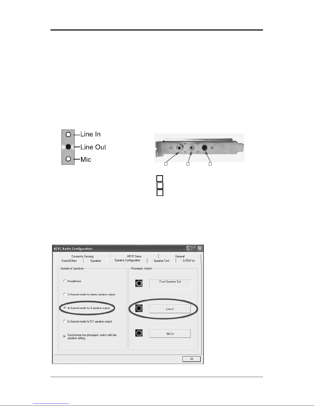
Description:
Connect two speakers to the back panels Line Out connector and two
speakers to one Line Out connector on the S-Bracket, or connect all two
speakers to one connector on the S-Bracket. If you want to use the Line In
function, please click the Rear Speaker Out button (shown below)
+
Method 2: Using S-BRACKET connectors:
The S-Bracket (shown on page 17) is an optional accessory. To use the
S-Bracket, you should select the correct setting in the software utility. For
information about the setting, refer to selecting 4- or 6- Channel Settings later
in this section.
Connector configurations for 4- and 6- channel using S-Bracket are described
below:
4-Channel Analog Audio Output
#
$%
1 SPDIF jack (coaxial)
2 Rear Speaker Out
3 No function
Page 15
#
6-Channel Analog Audio Output
Description:
Connect two speakers to the back panels Line Out connector and four
speakers to the Line Out connector of the S-Bracket, or attach all six speakers
to the connector on the S-Bracket. If you want to use the Line In and MIC
functions at the same time, please click the Rear Speaker Out and Center/
Subwoofer Speaker Out buttons (shown below).
Back Panel S-Bracket
(Front channels)
+
#
$%
1 SPDIF jack (coaxial)
2 Rear Speaker Out
3 Center and Subwoofer Out
Page 16
$
Technical Reference Booklet
CONNECTORS AND HEADERS
The motherboard provides connectors to connect to the FDD, IDE HDD, USB
Ports and to CPU/System FAN etc.
Floppy Disk Drive Connector - CN3
The motherboard provides a standard floppy disk drive connector that supports
1.44M, 2.88M floppy disk types.
Hard Disk Connectors - CN1
The motherboard has a 32-bit Enhanced PCI IDE and Ultra DMA 33/66/100
controller that provides PIO mode 0~4, Bus Master, and Ultra DMA 33/66/100
function. You can connect up to two hard disk drives, CD-ROMs, 120MB Floppy
(reserved for future BIOS) and other devices.
CN1 (Primary IDE Connector)
CN1 connects can connect a ide device, please set the jumper on IDE device
as Master.
CN3
CN1
1
1
J
S
\
G
S
R
R
V
I
Q
S
Z
I
Page 17

%
10
9
2
1
J19
S-Bracket (SPDIF) /CEN/LFE/Surround Output Connector - J19 for AC97 only
(optional)
This connector allows you to connect a S-Bracket for a digital interface (SPDIF).
The S-Bracket offers 1 SPDIF jack for digital audio transmission and 2 analog
Line-Out jacks for other 4-channel audio outputs. So you can use Line in, Mic
in and 6 channel audio output features at the same time.
PIN SIGNAL DESCRIPTION
1 SOUT-L Audio left surrounding output
2 SOUT-R Audio right surrounding output
3 GND Ground
4 GND Ground
5 CET-OUT Audio center output
6 LFE-OUT Audio bass output
7 GND Ground
8 SPDIF S/PDIF input
9 KEY NC
10 SPDFO S/PDIF output
S-Bracket Cable (optional)
Connect to J19
Rear Speaker Out
Center and Subwoofer Out
J
S
\
G
S
R
R
V
I
Q
S
Z
I
Page 18

&
Technical Reference Booklet
SPDIF Header - J29 for HD Audio (optional)
This header provides a SPDIF (Sony/Philips Digital Interface) output to digital
multimedia device through fiber or coaxial connector.
SPDIF-IN/OUT: J29 (for HDA only)
PIN SIGNAL DESCRIPTION
2 SPDIF-out SPDIF-out
3 NC NC
4 NC NC
8 GND GND
1 SPDIF-in SPDIF-in
5 NC NC
7 GND GND
J29
1
2
SPDIF-in
SPDIF-out
6 NC NC
J
S
\
G
S
R
R
V
I
Q
S
Z
I
Page 19

'
Fan Power Connectors - CPUFAN/SYSFAN (optional)
The CPUFAN (processor fan) and SYSFAN (system fan) support system cooling
fans using +12V via a four/three-pin head connector. When connecting the
wire to the connectors, always take note that the red wire is the positive and
should be connected to the +12V, the black wire is Ground and should be
connected to GND. If the motherboard has a System Hardware Monitor chipset
onboard, you must use a specially designed fan with speed sensor to take
advantage of the CPU fan control.
SYS FAN
CPU FAN
1
1
J
S
\
G
S
R
R
V
I
Q
S
Z
I
Page 20

Technical Reference Booklet
CD-IN Connector - J30 (optional)
The connector is for CD-ROM Drive.
1
PIN Assignment
1 CD-L
2 GND
3 GND
4 CD-R
J30 - Pin Definition
J30
J
S
\
G
S
R
R
V
I
Q
S
Z
I
Power LED - D64, D65 (optional)
The green LED lights when the system is in the power-on state.
The red LED lights whenever AC power is attached, irrespective of whether the
system is powered-on, powered-off or in standby mode.
J
S
\
G
S
R
R
V
I
Q
S
Z
I
D64- +5VLED (Green)
D65- 5VSBLED (Red)
Page 21

Serial ATA Hard Disk Connectors SATA-1/SATA-2/SATA-3/SATA-4 (optional)
The motherboard has four SATA connectors. The motherboard provides optional
dual high-speed Serial ATA interface ports, SATA-1, SATA-2, SATA-3,SATA-4.
Each supports 1
st
generation serial ATA data rates of 300MB/s. Both connector
types are fully compliant with Serial ATAII specifications. Each Serial ATA
connector can connect to 1 hard disk device.
PIN SIGNAL
1 GND
2 TXP
3 TXN
4 GND
5RXN
6RXP
7 GND
SATA-2
SATA-1
SATA-3
SATA-4
SATA-1/SATA-2/SATA-3/SATA-4 - Pin Definition
J
S
\
G
S
R
R
V
I
Q
S
Z
I
Page 22

Technical Reference Booklet
Serial ATA Cable
Please do not fold the serial ATA cable at a 90 degree angle as this
will cause a loss of data during the transmission.
Serial ATA Hard Disk Devices Power Cable (optional)
Connect one end of the SATA cable to the motherboard, and connect the other
end to the SATA Hard Disk.
Page 23

!
Front Panel Audio Header - FP_S1
Note: In order to utilize the front audio header, your chassis must have a
front audio connector. Also please make sure the pin assignment on the
cable is the same as the pin assignment on the motherboard header. To
find out if the chassis you are buying supports front audio connection,
please contact your dealer.
FP_S1
FP_S1 - Pin Definition
Pin Signal Description
1 PORT 1L Analog Port1 - Left channel
2 GND Ground
3 PORT 1R Analog Port 1 - Right channel
4 PRESENCE Active low signal - signals BIOS that a
High Definition Audio dongle is connected to
the analog header. PRESENCE=0 when
a High Definition Audio dongle is connected.
5 PORT 2R Analog Port 2 - Right channel
6 SENSE1_RETIRN Jack detection return from front panel JACK1
7 SENSE_SEND Jack detection sense line from the High
Definition Audio Codec jack detection
resistor network
8 KEY Connector Key
9 PORT 2L Analog Port2 - Left channel
10 SENSE2_RETIRN Jack detection return from front panel JACK2
10
9
2
1
J
S
\
G
S
R
R
V
I
Q
S
Z
I
Page 24

"
Technical Reference Booklet
IEEE 1394 Connector: CN9/CN10 (optional)
The motherboard provides two 1394 pin headers that allow you to connect
IEEE 1394 ports.
CN10
1
2
9
10
IEEE 1394 Cable (optional)
CN9/CN10 - Pin Definition
PIN Assignment
1TPA+
2TPA3 Ground
4 Ground
5 TPB+
6 TPB7 Cable power
8 Cable power
9 Key (no pin)
10 Ground
1
2
9
10
CN9
J
S
\
G
S
R
R
V
I
Q
S
Z
I
Page 25

#
USB Connectors - FP-U1/FP-U2 (optional)
This motherboard has eight USB ports. Some computer cases have a special
module that mounts USB ports at the front of the case. If you have this kind of
case, use the auxiliary USB connectors FP-U1/FP-U2 to connect the front
mounted ports to the motherboard.
10
9
2
1
FP-U1
PIN Assignment
1 VCC
2 VCC
3 USBP04 USBP15 USBP0+
6 USBP1+
7 GND
8 GND
9 KEY
10 OC#
FP-U1/FP-U2 - Pin Definition
FP-U2
10
9
2
1
J
S
\
G
S
R
R
V
I
Q
S
Z
I
Page 26

$
Technical Reference Booklet
Front Panel Header - FP1
The motherboard provides one front panel connector.
FP1
NC
VCC
KEY
KEYLOCK
GND
IRRX
SPEAKER
GND
KEY
IRTX
NC
VCC
GND
KEY
GND
PWR_SW
RESET
NC
KEY
GND
PW_LED-
PW_LED+
HDD_LEDHDD_LED+
24 23
16
1718
20
22 21
19
15
13
7
11
9
5
3
1
14
6
8
10
12
2
4
J
S
\
G
S
R
R
V
I
Q
S
Z
I
Page 27

%
CMOS Clear - JP1
JP1 Selection
1-2* Normal*
2-3 CMOS Clear
Jumper Setting
This chapter explains how to configure the motherboards hardware. Before
using your computer, make sure all jumpers and DRAM modules are set
correctly. Refer to this chapter whenever in doubt.
Close Open * = Default setting.
JP1
J
S
\
G
S
R
R
V
I
Q
S
Z
I
Page 28

&
Technical Reference Booklet
Slots
The motherboard provides one PCI-E X16 slot, one PCI-E X4 slot and three
32-bit PCI bus slots.
PCI-E X16 Slot
PCI Slots
PCI (Peripheral Component Interconnect) Slots
The PCI slots allow you to insert expansion cards to meet your needs. When
adding or removing expansion cards, make sure that you unplug the power
supply first. Read the documentation for the expansion card and make any
necessary hardware or software settings for the expansion card, such as
jumpers, switches or BIOS configuration.
PCI-E X4 Slot
J
S
\
G
S
R
R
V
I
Q
S
Z
I
Page 29

'
CPU Installation
Please follow the steps below to install the CPU.
1.Use index finger and thumb to
move metal lever so it is separated
from the bottom steel shell grip
hook.
2.Use index finger to lift the top steel
shell.
3.Use index finger and thumb to
place the CPU onto the plastic body
(look for the gold arrow on the CPU.
The gold arrow should point away
from the lever pivot).
Page 30

!
Technical Reference Booklet
4.Use index finger and thumb to
press down metal lever, the cap will
be pushed up by the CPU; this may
also be done by removing the cap
beforehand.
5.Press the metal lever so it is
secured in the bottom steel shell
grip hook.
6. Its recommended that the CPU heatsink should be an approval by Intel
corporation design for Prescott CPU. Choose the orientation of the thermal
solution for optimal wire routing to the fan header on the motherboard, Position
the thermal solution over the processor. Ensure the fan wiring is positioned to
prevent wire pinching between the heatsink and the processor, or between the
heatsink clip and the socket.
Page 31

!
7. Align the fastener tips with the
motherboard hole pattern, insert the
fastener tips into the holes, guiding
the wires to avoid pinching. The
fasteners will slide through the
motherboard holes with no insertion
force.
8.Engage the fasteners caps. Apply
thumb pressure to the top of each
of the 4 fastener caps, there is no
specific order of engagement, you
will hear a click upon full
engagement.
9. Gently rotate the cap clockwise
1/4 turn.
10. At last, attach the fan wire
connector to the 4 pin fan header
connector on the motherboard
labeled CPU FAN.
Page 32

!
Technical Reference Booklet
Install DDRII DIMMs
Please follow the steps below to install DDRII DIMMs.
1. Locate the DDRII DIMM sockets.
2. Holding the DDRII DIMM by the edges, remove it from its antistatic package.
3. Make sure the clips at either end of the socket are pushed away from the
socket.
4. Position the DDRII DIMM above the socket. Align the middle notch in the
bottom edge of the DDRII DIMM with the key in the socket.
5. Insert the bottom edge of the DDRII DIMM into the socket.
6. When the DDRII DIMM is seated, push down on the top edge of the DDR
II DIMM until the retaining clips at the ends of the socket snap into place.
Note: Please turn the system off before installing or removing any device,
otherwise system damage can occur.
Page 33

!!
CrossFire SETUP
If you want to set up the CrossFire, the Master card should be inserted into the
PCIx16 slot and the Slave card should be inserted into the PCIEx4 Slave slot
properly.
Make sure that the card is inserted in correct slot.
Installing Driver
After setting up the Windows, you need to install the 8.15 driver or later which
must include the Catalyst Control Centre (CCC).
Step1
Page 34

!"
Technical Reference Booklet
In the CCC advanced mode, you need to click the check box to enable the
CrossFire.
Step 2
Step3
Step4
After CrossFire is enabled successfully, you will be able to see that CrossFire
has started.
Click Standard View as default
Click CrossFire
TM
Select the check box
Page 35

!#
BIOS SETUP
About the Setup Utility
The motherboard uses the latest Award BIOS with support for Windows Plug
and Play. The CMOS chip on the motherboard contains the ROM setup
instructions for configuring the motherboard BIOS.
The BIOS (Basic Input and Output System) Setup Utility displays the systems
configuration status and provides you with options to set system parameters.
The parameters are stored in battery-backed-up CMOS RAM that saves this
information when the power is turned off. When the system is turned back on,
the system is configured with the values you stored in CMOS.
The BIOS Setup Utility enables you to configure:
Hard drives, diskette drives and peripherals
Video display type and display options
Password protection to prevent unauthorized use
Power Management features
The settings made in the Setup Utility affect how the computer performs.
Before using the Setup Utility, ensure that you understand the Setup Utility
options.
This chapter provides explanations for Setup Utility options.
The Standard Configuration
A standard configuration has already been set in the Setup Utility. However, we
recommend that you read this chapter in case you need to make any changes
in the future.
This Setup Utility should be used:
- when changing the system configuration
- when a configuration error is detected and you are prompted to make
changes to the Setup Utility
- when trying to resolve IRQ conflicts
- when making changes to the Power Management configuration
- when changing the password or making other changes to the Security
Setup
Entering the Setup Utility
When you power on the system, BIOS enters the Power-On Self Test (POST)
routines. POST is a series of built-in diagnostics performed by the BIOS. After
the POST routines are completed, the following message appears:
Page 36

!$
Technical Reference Booklet
Main Menu
Once you enter the Award BIOS CMOS Setup Utility, the Main Menu will appear
on the screen. The Main Menu allows you to select from various setup functions
and two exit choices. Use the arrow keys to select among the items and press
<Enter> to accept and enter the sub-menu.
Phoenix - Award WorkstationBIOS CMOS Setup Utility
&
Standard CMOS Features
&
Frequency/Voltage Control
&
Advanced BIOS Features Load Fail-Safe Defaults
&
Advanced Chipset Features Load Optimized Defaults
&
Integrated Peripherals Set Supervisor Password
&
Power Management Setup Set User Password
&
PnP/PCI Configurations Save & Exit Setup
&
PC Health Status Exit Without Saving
Esc : Quit éêèç : Select Item
F10 : Save & Exit Setup
Time, Date, Hard Disk Type ... ...
(Note : The sample BIOS Setup Menu included here only shows a typical
case, and may not be exactly the same as the one on your unit.)
Note that a brief description of each highlighted item will appear at the bottom
of the screen.
Standard This setup page includes all the items of Award special
CMOS Features standard features.
Advanced BIOS This setup page includes all the items of Award special
Features enhanced features.
Advanced This setup page includes all the items of chipset special
Chipset Features features.
Integrated This section page includes all the items of IDE hard drive
Peripherals and Programmed Input / Output features.
Power This entry only appears if your system supports Power
Management Management Green PC standards.
Setup
PNP/PCI This entry appears if your system supports PNP/PCI.
Configurations
PC Health Status Display CPU and Case Fan Speed etc.
Page 37

!%
Frequency/ CPU speed setting are settings of CPU speed. You should
Voltage Control refer to your CPU marking.
Load Optimized The chipset defaults are settings which provide for maximum
Defaults system performance. While Award has designed the
custom BIOS to maximize performance, the manufacturer
has the right to change these defaults to meet its needs.
Set Supervisor/ Changes, sets, or disables password. It allows you to limit
User Password access to the system and the Setup Program.
Save & Exit Saves value changes to CMOS and exits setup.
Setup
Exit Without Abandons all CMOS value changes and exits setup.
Saving
Standard CMOS Features
The items in Standard CMOS Setup Menu are divided into 10 categories. Each
category includes one or more setup items. Use the arrow keys to highlight the
item and then use the <PgUp> or <PgDn> key to select the desired value in
each item.
Phoenix - Award WorkstationBIOS CMOS Setup Utility
Standard CMOS Features
Date (mm :dd :yy) Sat. Jan 01 2005 Item Help
Time (hh :mm:ss) 11 : 1 : 35
Menu Level
&
&
IDE Primary Master [Press Enter 4303 MB]
&
IDE Primary Slave [None] Change the day, month,
&
IDE Secondary Master [None] year and century
&
IDE Secondary Slave [None]
Drive A [1.44M, 3.5 in.]
Drive B [None]
Video [EGA/VGA]
Halt on [All, but keyboard]
Base Memory 640K
Extended Memory 30720K
Total Memory 31744K
éêèçMove Enter: Select +/-/PU/PD : Value F10 : Save ESC : Exit F1 :General Help
F5 : Previous Values F6 : Fail-Safe Defaults F7 : Optimized Defaults
(Note : The sample BIOS Setup Menu included here only shows a typical
case, and may not be exactly the same as the one on your unit.)
Page 38

!&
Technical Reference Booklet
Date The date format is <day-of-the-week>. <month> <day> <year>.
Time The time format is <hour> <Minute> <second> displayed in
24-hour military-time clock. For example, 1 p. m. is displayed
as 13:00:00.
Primary These categories identify the types of the two channels that
Master/Primary have been installed in the computer.
Slave/Secondary
Master/Secondary If the controller of the HDD interface is SCSI, the selection shall
be None.
Drive A Type / This category identifies the drive types which have been installed
Drive B Type in the computer.
Video The default setting is EGA/VGA.
Halt on You can select which type of error will cause the system to halt.
Advanced BIOS Features
This section allows you to configure your system for basic operation. You have the
opportunity to select the systems default speed, boot-up sequence, keyboard operation,
shadowing and security.
Advanced Chipset Features
The Chipset Features Setup option is used to change the values of the chipset registers.
These registers control most of the system options in the computer.
This section allows you to configure the system based on the specific features of the
installed chipset. This chipset manages bus speeds and access to system memory
resources, such as DRAM and the external cache. It must be stated that these items
should not be altered. The default settings have been chosen because they provide the
best operating conditions for your system.
Integrated Peripherals
The Integrated Peripherals Setup allows the user to configure the onboard IDE controller,
floppy disk controller, the printer port and the serial ports.
Power Management Setup
The Power Management Setup Menu allows you to configure your system to save the
most energy while operating in a manner consistent with your own style of computer
use.
PNP/PCI Configurations
This section describes how to configure the PCI bus system. This section covers some
very technical items and it is recommended that only experienced users should make
any changes to the default settings.
PC Health Status
The PC Health Status displays CPU and Case Fan Speed.
Frequency/Voltage Control
This section allows you to set CPU Speed.
Page 39

!'
Set Supervisor/User Password
When this function is selected, the following message appears at the center of
the screen to assist you in creating a password.
ENTER PASSWORD
Type the password, up to eight characters, and press <Enter>. The password
typed now will clear any previously entered password from CMOS memory.
You will be asked to confirm the password. Type the password again and
press <Enter>. You may also press <Esc> to abort the selection. To disable
password, just press <Enter> when you are prompted to enter password. A
message will confirm the password being disabled. Once the password is
disabled, the system will boot and you can enter BIOS Setup freely.
PASSWORD DISABLED
If you have selected System in Security Option of BIOS Features Setup
menu, you will be prompted for the password every time the system reboots or
any time you try to enter BIOS Setup. If you have selected Setup at Security
Option from BIOS Features Setup menu, you will be prompted for the
password only when you enter BIOS Setup.
Supervisor Password has higher priority than User Password. You can use
Supervisor Password when booting the system or entering BIOS Setup to
modify all settings. Also you can use User Password when booting the system
or entering BIOS Setup but can not modify any setting if Supervisor Password
is enabled.
Save & Exit Setup
Navigate to this option and press <Enter> to save the changes that you have
made in the Setup Utility and exit the Setup Utility. When the Save and Exit
dialog box appears, press <Y> to save and exit, or press <N> to return to the
main menu.
Exit Without Saving
Navigate to this option and press <Enter> to discard any changes that you
have made in the Setup Utility and exit the Setup Utility. When the Exit Without
Saving dialog box appears, press <Y> to discard changes and exit, or press
<N> to return to the main menu.
Note: If you have made settings that you do not want to save, use the Exit
Without Saving item and press <Y> to discard any changes you have.
Page 40

"
Technical Reference Booklet
FLASH Update Procedure
The program AWDFLASH.EXE is included on the driver CD (D:\Utility\
AWDFLASH.EXE). Please follow the recommended procedure to update the
flash BIOS, as listed below.
1. Create a DOS-bootable floppy diskette. Copy the new BIOS file (just
obtained or downloaded) and the utility program AWDFLASH.EXE to the
diskette.
2. Allow the PC system to boot from the DOS diskette.
3. At the DOS prompt, type
AWDFLASH<ENTER>
4. Enter the file name of the new BIOS.
5. The question: Do you want to save BIOS (Y/N)? is displayed.
Press N if there is no need to save the existing BIOS.
Press Y if a backup copy of the existing BIOS is needed.
(A file name has to be assigned to the existing BIOS binary file.)
6. The message : Press Y to program or N to exit is displayed. Type
Y<ENTER>
7. Wait until the flash-update is completed.
8. Restart the PC.
Warning : - Do not turn off or RESET the computer during the flash
process.
- If you are not sure how to upgrade the BIOS, please take
your computer to an Authorized Service Center and have
a trained technician do the work for you.
Page 41

"
Realtek HD Audio Driver Setup
Getting Started
After Realtek HD Audio Driver being installed (insert the driver CD and follow
the on-screen instructions), Realtek HD Audio Manager icon will show in
System tray as below. Double click the icon and the control panel will appear:
Sound Effect
After clicking on the Sound Effect tab, 3 sections Environment, Equalizer
and Karaoke are available for selection.
Environment Simulation
You will be able to enjoy different sound experience by pulling down the arrow,
totally 23 kinds of sound effect will be shown for selection. Realtek HD Audio
Sound Manager also provides five popular settings Stone Corridor,
Bathroom, Sewer pipe, Arena and Audio Corridor for quick enjoyment.
Page 42

"
Technical Reference Booklet
Equalizer Selection
The Equalizer section allows you to create your own preferred settings by
utilizing this tool.
In standard 10 bands of equalizer, ranging from 100Hz to 16KHz are available:
Frequently Used Equalizer Setting
Realtek recognizes the needs that you might have. By leveraging our long
experience at audio field, Realtek HD Audio Sound Manager provides you
certain optimized equalizer settings that are frequently used for your quick
enjoyment.
How to Use
Other than the buttons Pop Live Club & Rock shown on the page, to pull
down the arrow in Others , you will find more optimized settings available to
you.
Karaoke Mode
Karaoke mode brings Karaoke fun back home by simply using the music you
usually play, Karaoke mode can help you eliminate the vocal of the song or
adjust the key to accommodate your range.
Vocal Cancellation: Single click on Voice Cancellation, the vocals of the
songs will be erased, while the background music is
still playing which lets you take over the vocal part.
Key Adjustment: Using Up / Down Arrow to find a key which better fits
your vocal range.
Page 43

"!
Mixer
Realtek HD Audio Sound Manager integrates Microsofts Volume Control
functions into the Mixer page. This gives you the advantage to you to create
your favorite sound effect in one single tool.
Playback control
Mute
You may choose to mute single or multiple volume controls or to completely
mute sound output.
Tool
√ Show the following volume control
This is to let you freely decide which volume control items to be
displayed, total 13 items to be chosen.
√ Advanced controls
√ Enable playback multi-streaming
Page 44

""
Technical Reference Booklet
With this function, you will be able to have an audio chat with your friends via
headphone (stream 1 from front panel) while still have music (stream 2 from
back panel) playing. At any given period, you can have maximum 2 streams
operating simultaneously.
Recording control
Mute
You may choose to mute single or multiple volume controls or to completely
mute sound input.
Tool
√√
√√
√ Show the following volume controls
This is to let you freely decide which volume control items to be displayed.
√√
√√
√ Advanced controls.
Advanced control is a Microphone Boost icon.
Once this item is checked, you will find advanced icon beside Front Pink
In & Mic Volume. With this, the input signal into Front Pink In & Mic
Volume will be strengthen.
√√
√√
√ Enable recording multi-streaming
At any given period, you can have maximum 2 streams operating
simultaneously.
Page 45

"#
Audio I/O
Realtek HD Audio Manager frees you from default speaker settings. Different
from before, for each jack, they are not limited to perform certain functions.
Instead, now each jack is able to be chosen to perform either output (i.e.
playback) function or input (i.e. Recording) function, we call this Retasking.
Audio I/O aims to help you setting jacks as you wish. Moreover, other than blue
to blue, pink to pink, the way that you used to do, Audio I/O would guide you to
other right jacks that can also serve as microphone / speaker / headphone.
Page 46

"$
Technical Reference Booklet
Speaker Configuration
Step 1: Plug in the device in any available jack.
Step 2: Dialogue connected device will pop up for your selection. Please
select the device you are trying to plug in.
* If the device is being plugged into the correct jack, you will be able to find
the icon beside the jack changed to the one that is same as your device.
* If not correct, Realtek HD Audio Manager will guide you to plug the device
into the correct jack.
Page 47

"%
Global Connector Settings
Click to access global connector settings
√ Mute rear panel when front headphone plugged in
Once this option is checked, whenever front headphone is plugged, the
music that is playing from the back panel, will be stopped.
√ Disable front panel jack detection (option)
Did not find any function on front panel jacks?
Please check if front jacks on your system are so-called AC97 jacks. If so,
please check this item to disable front panel jack detection.
√ Enable auto popup dialogue, when device has been plugged in.
Once this item checked, the dialog Connected device, would not
automatically pop up when device plugged in.
S/PDIF
Short for Sony/Philips Digital
Interface, a standard audio file
transfer format. S/PDIF allows
the transfer of digital audio
signals from one device to
another without having to be
converted first to an analog
format. Maintaining the viability
of a digital signal prevents the
quality of the signal from
degrading when it is converted
to analog.
Page 48

"&
Technical Reference Booklet
√√
√√
√ Output Sampling Rate
- 44.1KHz: This is recommend while playing CD
- 48KHz: This is recommended while playing DVD or Dolby.
- 96KHz: This is recommended while playing DVD-Audio.
√√
√√
√ Output Source
- Output digital audio source: The digital audio format (such as .wav,
.mp3,.midi etc) will come out through S/PDIF-Out.
- S/PDIF-in to S/PDIF -out pass though mode: The data from S/PDIF-In
can be real-time played from S/PDIF-Out.
S/PDIF In Status
Lock:
This is to express if the S/PDIF In data has been successfully caught by codec
Sampling Rate
Data Validation:
This indicates if the input data is known to Realtek HD Audio Manager.
Copyright protection:
The input data can only be copied while Copy Free is shown; while No Copy
indicates the data is read only.
Real time S/PDIF-in monitor:
Not only S/PDIF out, but also other analog out (such as front /side/surround
speakers) can also output S/PDIF-in data real-time.
Speaker Calibration
After you have successfully plugged in speakers and assigned to the right
jacks, you are only one more step to go to enjoy the intended sound. We
provide Speaker Calibration to help you check if the speakers are located in
the correct position.
Page 49

"'
Microphone
This page is designed to provide you better microphone / recording quality.
Below picture indicates both Noise Suppression & Acoustic Echo
Cancellation are both enabled.
Noise Suppression
If you feel that the background noise, especially the sound generated from the
fan inside PC, is too loud? Try Noise Suppression, which allows you to cut off
and suppress disturbing noise.
Beam Forming
Also known as directional recording, this option lets you do the following:
Once beam forming is enabled; only the sound from certain direction will be
recorded. You will get the best quality if you chose 90° position, which we
recommend you to use, this effectively means that you speak right into the
microphone.
Note: A Stereo Microphone is required when using Beam Forming
function.
Acoustic Echo Cancellation
This function prevents playback sound from being recorded by microphone
together with your sound. For example, you might have chance to use VOIP
function through Internet with your friends. The voice of your friend will come
out from speakers (playback). However, the voice of your friend might also be
recorded into your microphone then go back to your friend through Internet. In
that case, your friend will hear his/her own voice again. With AEC (Acoustic
Echo Cancellation) enabled at your side, your friend can enjoy the benefit with
less echo.
Page 50

#
Technical Reference Booklet
Audio Demo
The section 3D Audio Demo grants you another possibility to enjoy your
sound. The Audio Demo allows you to listen to sound in an extraordinary way.
Information
This section provides information about your current system audio device.
Page 51

#
APPENDIX
Note to User:
The bundled driver CD contains all the drivers that the motherboard needs.
Each driver will install automatically once it is selected. Please select the
drivers that you want to install by clicking on the drivers button.
Page 52

#
Technical Reference Booklet
002BA8
 Loading...