

Page 1

1
Electronic Emission Notices
Federal Communications Commission (FCC) Statement
This equipment has been tested and found to comply with the limits for a Class B digital
device, pursuant to Part 15 of FCC Rules. These limits are designed to provide reasonable
protection against harmful interference in a residential installation. This equipment
generates, uses and can radiate radio frequency energy and, if not installed and used in
accordance with instructions contained in this manual, may cause harmful interference
to radio and television communications. However, there is no guarantee that interference
will not occur in a particular installation.
If this equipment does cause harmful interference to radio or television reception, which
can be determined by turning the equipment off and on, the user is encouraged to try to
correct the interference by one or more of the following measures:
- REORIENT OR RELOCATE THE RECEIVING ANTENNA
- INCREASE THE SEPARATION BETWEEN THE EQUIPMENT AND THE RECEIVER
- CONNECT THE EQUIPMENT INTO AN OUTLET ON A CIRCUIT DIFFERENT FROM
THAT OF THE RECEIVER
- CONSULT THE DEALER OR AN EXPERIENCED AUDIO/TELEVISION TECHNICIAN
NOTE: Connecting this device to peripheral devices that do not comply with Class B
requirements, or using an unshielded peripheral data cable, could also result in
harmful interference to radio or television reception.
The user is cautioned that any changes or modifications not expressly approved
by the party responsible for compliance could void the user’s authority to operate
this equipment.
To ensure that the use of this product does not contribute to interference, it is
necessary to use shielded I/O cables.
Copyright
This manual is copyrighted with all rights reserved. No portion of this manual may be
copied or reproduced by any means.
While every precaution has been taken in the preparation of this manual, no responsibility
for errors or omissions is assumed. Neither is any liability assumed for damages resulting
from the use of the information contained herein.
Trademarks
All brand names, logos and registered trademarks mentioned are property of their
respective owners.
Page 2

2
Technical Reference Booklet
Table of Contents
HARDWARE CONFIGURATION ....................................................... 4
Key Features .................................................................................................. 4
MOTHERBOARD LAYOUT ................................................................ 7
REAR PANEL .................................................................................... 8
AUDIO CONFIGURATION ................................................................ 10
SPEAKER CONFIGURATION ............................................................ 10
Method 1: 4/6 Surround audio output of back panel only ...................... 10
Method 2: Using S-Bracket connectors ................................................. 12
JACK-SENSING INSTRUCTION ........................................................ 15
CONNECTORS ................................................................................. 18
Floppy Disk Drive Connector:CN3 ......................................................... 18
Hard Disk Connectors:CN1 .................................................................. 18
Back Panel Bracket-Six Channel Audio Output Connector:CN7 ......... 19
Fan Power Connectors: CPUFAN/SYSFAN .......................................... 21
AUX-IN Connector:AUX1 ........................................................................ 22
CD-IN Connector:CDS1 ........................................................................ 22
Serial ATA Hard Disk Connectors:SATA1/SATA2/SATA3/SATA4 ............. 23
Front Panel Audio Header:FP-S1 .......................................................... 25
IEEE 1394 Connector:CN9 .................................................................... 26
USB Connectors:FP-U1/FP-U2 ............................................................. 28
Front Panel Header:FP1 ........................................................................ 29
JUMPER SETTING ............................................................................... 3 0
JP1 - CMOS Clear .................................................................................. 30
Keyboard Power Select Jumper: JP5 .................................................... 30
CPU Frequency Jumper: JP2/JP21 ....................................................... 30
Page 3

3
SLOTS .............................................................................................. 3 1
CPU INSTALLATION ........................................................................ 3 2
INSTALL DDR DIMMs ...................................................................... 35
MEMORY CONFIGURATIONS .......................................................... 36
Single Channel Mode ............................................................................ 36
Dual Channel Mode ............................................................................... 37
BIOS SETUP ..................................................................................... 38
Starting Setup ........................................................................................ 38
Main Menu .............................................................................................. 39
Standard CMOS Features ..................................................................... 40
Advanced BIOS Features ....................................................................... 41
Advanced Chipset Features .................................................................. 41
Integrated Peripherals ........................................................................... 41
Power Management Setup .................................................................... 41
PNP/PCI Configurations ........................................................................ 41
PC Health Status ................................................................................... 41
Frequency/Voltage Control..................................................................... 41
Set Supervisor/User Password ............................................................. 42
Flash Update Procedure ....................................................................... 43
APPENDIX ....................................................................................... 44
Page 4

4
Technical Reference Booklet
HARDWARE CONFIGURATION
Key Features :
Chipset
• Intel® 915G/915P/915GV/910GL Chipset.
Processor
• Supports Intel® Pentium® 4, Northwood and Prescott processors in
the 478-pin package (with 0.8V~1.6V voltage)
• Supports 64-bit PSB (Processor System Bus) frequency of 533MHz
(133MHz bus clock)
• Supports 64-bit PSB (Processor System Bus) frequency of 800MHz
(200MHz bus clock) (only for 915G/GV/P)
• Supports Hyper-Threading Technology.
VRM 10.1 (Voltage Regulator Modules) on Board
• Flexible motherboard design with on board VRD 10.1, easy to upgrade
with future Intel® Pentium® 4 processors.
• The Intel Pentium® 4 Processors built-in L2 Cache.
System Memory
• A total of two 184pin DDR SDRAM sockets.
• DIMM size from 64 Mbytes to 2Gbyte.
• Support Dual Channel 128-bit Wide Memory Interface
• Support DDR 333/400 DDR SDRAM memory type.
• 2.5V DRAM interface for DDR SDRAM.
System BIOS
• PnP, APM, ATAPI for Windows®2000/XP.
• Full support of ACPI & DMI.
• Auto detects and supports LBA harddisks with capacities over 160GB.
• Easy to upgrade BIOS by end-user.
On-board AC97 Sound (optional)
• Integrated AC97 controller with standard AC97 Codec.
• Direct Sound and Sound Blaster compatible.
• Full-Duplex 16-bit record and play back.
• PnP and APM 1.2 support.
• Windows®2000/XP drivers ready.
• Line-in, Line-out, Mic-in .
• Supports ALC650/655 AC97 Code for six sound channel output
(optional).
• ALC655 supports SPK-out, MIC-in, LINE-in, jack sensing.
Page 5

5
Hardware Configuration
Plug-and-Play
• Supports Plug and Play specification 1.1.
• Plug and Play for Windows®2000 as well as Windows®XP.
• Fully steerable PCI interrupts.
On-board I/O
• On board one PCI fast IDE ports supporting up to 2 ATA, ATA2 , Ultra
ATA33/66/100 IDE HDDs, CD-ROMs, ZIP drives and LS-120 drives
as boot drive.
• Support Bus Master IDE, Read transfers up to 100MB/s, Writes to
89MB/s.
• One ECP/EPP parallel port.
• One 16550 Compatible UART serial port (Two serial ports for 915P).
• One floppy port supports two FDD of 360KB, 720KB, 1.2MB , 1.44MB
and 2.88MB capacity.
• Eight USB ports.
• PS/2 keyboard connector.
• PS/2 mouse is supported.
• One Front Panel Sound Connector.
• Infrared (IrDA) is supported via a header.
On-board Realtek RT8100C LAN (optional)
• Integrated 10/100 transceiver.
• Supports Full Duplex flow control(IEEE802.3x)
• Fully compliant with IEEE802.3, IEEE802.3u, IEEE802.3ab.
• Supports Wake-On-LAN function and remote wake-up.
• Transmit/Receive FIFO (8K/64K) support.
On-board VGA (only for 915G/GV/910GL)
• Core Frequency of 333MHz.
• 3D Setup Render Engine.
• High Quality Texture Engine.
• 3D Graphics Rasterization Enhancements.
• Full 2D H/W Acceleration.
• Motion Video Acceleration.
• Up to 2048x1536 in 8 bit Color at 85Hz Refresh.
• H/W Motion Compensation Assistance for S/W MPEG2 Decode.
• Software DVD at 30fps.
• Integrated 24-bit 350MHz RAMDAC.
Page 6

6
Technical Reference Booklet
Static electricity can harm delicate components of the motherboard.
To prevent damage caused by static electricity, discharge the static
electricity from your body before you touch any of the computers
electronic components.
PCI Express Graphics interface
• One 16-lane(X16 port) PCI Express port intended for Graphics Attach,
Fully compliant to the PCI Express Base Specification revision 1.0a.
• A base PCI Express frequency of 2.5GB/s only.
• PCI Express supports and Enhanced Addressing Mechanism.
• ADD2 card utilizes PCI Express Graphics x16 connector.
PCI ExpressX1 Ports
• Full PCI Express 1.0a compliant.
• Two virtual channel support for full isochronous data transfers.
• Supports for full 2.5GB/s bandwidth in each direction per X1 lane.
Expanded USB Support
• Includes 4 UHCI host controllers,increasing the number of external
ports to eight.
• Includes 1 EHCI USB2.0 Host Controller that supports all eight ports
(Bandwidth shared between eight ports).
Power Management
• Supports SMM, APM and ACPI.
• Break switch for instant suspend/resume on system operations.
• Energy star “Green PC” compliant.
• Hardware monitoring circuit is supported, provide voltage,
temperature, fan speed, etc. monitoring (optional).
• Supports suspend-to-RAM(STR) (optional).
• External Modem Ring-in Wake-up support.
On board IEEE1394 OHCI Link Controller(optional)
• Compliant with 1394 open HCI specifications v1.0 and v1.1.
• Integrated 400Mbit 2 ports PHY.
Integrated Serial ATA host Controller
• Independent DMA operation on four ports.
• Data transfer rates of 150Mb/s.
• RAID feature support (optional).
Expansion Slots
• 1 PCI Express X16 slot.
• 1 PCI Express X1 slots.
• 2 PCI bus master slots - ver. 2.1 compliant.
Page 7

7
Motherboard Layout
The following diagrams show the relative positions of the jumpers,
connectors, major components and memory banks on the motherboard.
NOTE
1) Be sure to check the cable orientation in order to match the colored strip to
the pin1 end of the connector.
2) When you start up the system, please wait for 5 seconds after you power
on AC.
3) It is not recommended to add a metal spacer plate on the back of the
Socket478. Otherwise, some components will be short and damaged.
# The LAN, CN7&Video out connectors are optional.
# The ALC650/655 embeds an internal analog switch (by driver software) to
share LINE input with Surround output, and share MIC input with CENTER/LFE
output.
Motherboard layout
Page 8

8
Technical Reference Booklet
PIN SIGNAL DESCRIPTION
1 VCC +5V/5VSB (optional)
2 -Data 0 Negative Data Channel 0
3 +Data0 Positive Data Channel 0
4 GND Ground
5 VCC +5V/5VSB (optional)
6 -Data 1 Negative Data Channel 1
7 +Data 1 Positive Data Channel 1
8 GND Ground
Rear Panel
The back panel provides the following connectors:
Mouse Connector
The mainboard provides a standard PS/2
®
mouse mini DIN connector for
attaching a PS/2
®
mouse.You can plug a PS/2® mouse directly into this
connector.
Keyboard Connector
The mainboard provides a standard PS/2
®
keyboard mini DIN connector
for attaching a PS/2
®
keyboard.You can plug a PS/2® keyboard directly into
this connector.
USB 2.0 Connector
The mainboard provides a UHCI (Universal Host Controller Interface)
Universal Serial Bus root for attaching USB devices such as keyboard, mouse
or other USB-compatible devices.You can plug the USB device directly into
the connector.
USB 2.0 Connector DescriptionUSB 2.0 Connector
Page 9

9
VIA VT6307 IEEE 1394 Connector (Optional)
The mainboard provides a IEEE 1394 Connector and allows you to
connect a IEEE 1394 device directly to the connector.
Serial Port Connector: COM1
The Port is 16550A high speed communication ports that send/receive
16bytes FIFOs. You can attach a serial mouse or other serial devices directly
to the connectors.
Video Out Connector (Optional)
The mainboard provides a Video out port to connect a 15-pin analog
video monitor.
LAN Jack (Optional)
The mainboard provides one standard RJ-45 jack for connection to Local
Area Network(LAN).You can connect a network cable to the LAN jack.
Parallel Port Connector:LPT
The mainboard provides a 25-pin female centronic connector as LPT. A
parallel port is a standard printer port that supports Enhanced Parallel Port
(EPP) and Extended Capabilities Parallel Port (ECP) mode.
Audio Port Connector
Line-out is a connector for Speakers or Headphones. Line In is used for
external CD player, Tape player, or other audio devices. Mic In is a connector
for microphones. The ALC650/655 embeds an internal analog switch (by driver
software) to share LINE input with Surround output, and share MIC input with
CENTER/LFE output.
The ALC655 embeds the jack sensing function.When you plug an audio
device into the corresponding connector, the system will show you what you
pluged into the motherboard.
Rear Panel
Page 10

10
Technical Reference Booklet
Audio Configuration
After installing the audio driver, you can select 4/6 channel surround
audio output in software utility and then connect surround speakers to
appropriate audio ports.
There are two ways to obtain 4/6 channel surround audio output:
1. 4/6 surround audio output of back panel only. All surround speaker
connect to audio connector.
2. S-Bracket (optional cable). You have installed S-Bracket into the
computer, and then connect two front speakers to back panel’s
“Line-out” port, and the rest of speakers to S-Bracket. Detail connection
is refer to Page 20.
Speaker Configuration
Method 1: 4/6 Surround audio output of back panel only.
After installing the audio drivers, you can attach the speakers for 2-/4-/6channel audio output. Always connect the speakers to the LINE OUT
connectors. Different connector configurations for 2-/4-/6-channel
operations are listed below:
2-Channel
4-Channel 6-Channel
In 2-channel configuration,
Line Out, Line In and MIC
functions all exist.
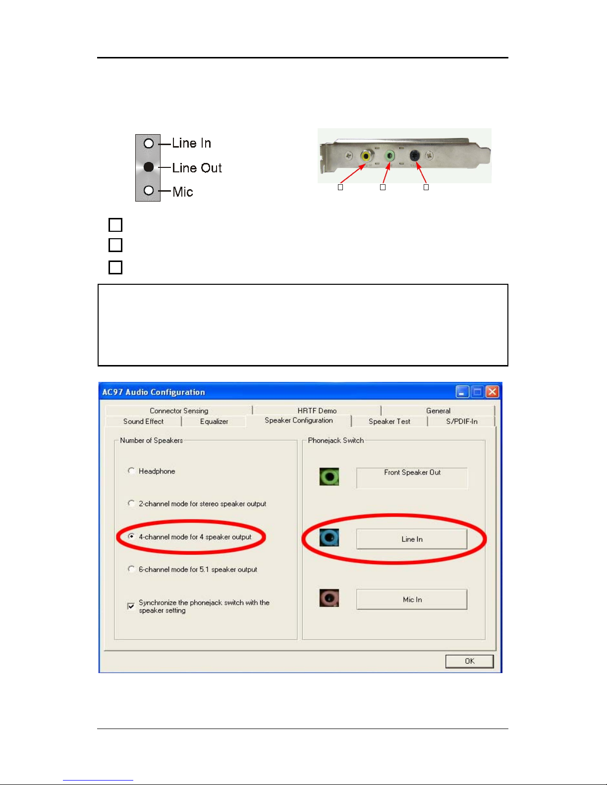
When set to 4-channel
configuration, Line In
is replaced by Rear
Speaker Out. Line in
function does not exist.
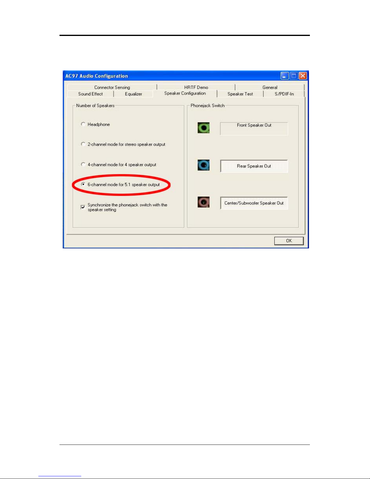
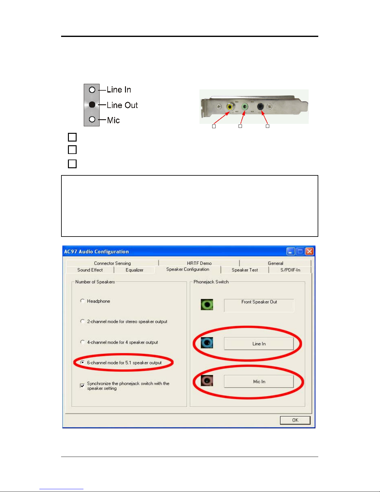
When set to 6-channel
configuration, Line In
is replaced by Rear
Speaker Out. Mic is
replaced by Center/
Subwoofer Speaker Out.
Line in and Mic do not
exist function.
Page 11

11
Software Configuration
In utility, double click “AC97 Audio configuration” icon from the
window tray on the right bottom.
Then the “AC97 Audio Configuration” will appear. Click on the Speaker
Configuration tab to select the audio mode.
A. When you choose 4-channel mode for 4 speaker output, the selected item
is showed as below (Figure1)
(Figure1)
Page 12
12
Technical Reference Booklet
B. When you choose 6-channel mode for 5.1 speaker output, the selected
item is showed as below (Figure2)
Method 2: Using S-BRACKET connectors:
S-Bracket (The S-Bracket is showed in page 20) is an optional accessory.
It gives access to analog and digital audio output by integrating both SPDIF
and analog LINE OUT connectors. To use the S-Bracket, you should select
correct setting in the software utility. For information about the setting, refer to
selecting 4- or 6- Channel Setting later in the section.
Connector configurations for 4- and 6- channel using S-Bracket are
described below:
(Figure2)
Page 13
13
Back Panel
S-Bracket
(Front channels)
4-Channel Analog Audio Output
Description:
Connect two speakers to back panel’s Line Out connector and two
speakers to one Line Out connector of S-Bracket, or four speaker to
connector of S-Bracket. If you want to use Line In function, please click
the Rear Speaker Out button (showed as below)
Using S-Bracket Connector
1
23
+
1
2
3
SPDIF jack (coaxial)
Rear Speaker Out
No function
Page 14
14
Technical Reference Booklet
Back Panel
S-Bracket
(Front channels)
6-Channel Analog Audio Output
Description:
Connect two speakers to back panel’s Line Out connector and four
speakers to both Line Out connectors of S-Bracket, If you want to use
Line In and MIC function at the same time, please click the Rear
Speaker Out and Center/Subwoofer Speaker Out buttons. (showed as
below)
1
23
+
1
2
3
SPDIF jack (coaxial)
Rear Speaker Out
Center and Subwoofer Out
Page 15

15
Jack-Sensing Instruction
Jack-Sensing provides audio connectors error-detection function.
Install Microsoft DirectX8.1 before to enable Jack-Sensing support
for Windows 2000/XP.
Jack-Sensing includes 2 parts:AUTO and MANUAL. Following is an
example for 2 channels (Windows XP):
Introduction of audio connectors
You may connect CDROM, Walkman or others audio input devices to Line In
jack. speakers, earphone or others output devices to Line Out jack. and
microphone to MIC In jack.
Jack-sensing instruction
Page 16

16
Technical Reference Booklet
Auto-detecting:
Please connect the devices to the right jacks as above. A window will appear
as below picture if you setup the devices properly.
If you set wrong with the connectors, the warning message will come out as
following picture.
Page 17

17
Manual setting:
If the device picture shows different from what you set, please press
“Correction...” to set.
Manual Setting
Page 18

18
Technical Reference Booklet
Connectors
The mainboard provides connectors to connect to FDD, IDE HDD, USB
Ports ,IEEE1394, SPDIFand CPU/System FAN etc.
Floppy Disk Drive Connector:CN3
The mainboard provides a standard floppy disk drive connector that
supports 360K, 720K, 1.2M, 1.44M and 2.88M floppy disk types.
Hard Disk Connectors:CN1
The mainboard has a 32-bit Enhanced PCI IDE and Ultra DMA 33/66/100
controller that provides PIO mode 0~4, Bus Master, and Ultra DMA 33/66/100
function. You can connect up to four hard disk drives, CD-ROM, 120MB Floppy
(reserved for future BIOS) and other devices.
CN1 (Primary IDE Connector)
The first hard drive should always be connected to CN1.CN1 can connect
a Master and a Slave drive.You must configure second hard drive to Slave
mode by setting the jumper accordingly.
CN3
CN1
1
1
Page 19

19
CN7
2
1
10
9
S-Bracket(SPDIF)/CEN/LFE/Surround Output Connector:
CN7 (optional)
The connector allows you to connect a S-Bracket for a Digital Interface
(SPDIF). The S-Bracket offers 1 SPDIF jacks for digital audio transmission
and 2 analog Line-Out jacks for other 4-channel audio output. So you can use
Line in, Mic in and 6 channel audio output features at the same time.
Connectors
Page 20

20
Technical Reference Booklet
PIN SIGNAL DESCRIPTION
1 SOUT-L Audio left surrounding output
2 SOUT-R Audio right surrounding output
3 GND Ground
4 GND Ground
5 CET-OUT Audio center output
6 LFE-OUT Audio bass output
7 GND Ground
8 SPDIF S/PDIF input
9 KEY NC
10 SPDFO S/PDIF output
CN7-S-Bracket
S-Bracket Cable (optional)
Connect to CN7
SPDIF jack (coaxial)
Rear Speaker Out
Center and Subwoofer Out
Page 21

21
Fan Power Connectors:CPUFAN/SYSFAN
The CPUFAN (processor fan), SYSFAN (system fan) support system cooling fan with +12V.It supports three-pin head connector. When connecting the
wire to the connectors, always take note that the red wire is the positive and
should be connected to the +12V, the black wire is Ground and should be
connected to GND. If the mainboard has a System Hardware Monitor chipset
on-board, you must use a specially designed fan with speed sensor to take
advantage of the CPU fan control.
SYS FAN
CPU FAN
1
1
Connectors
Page 22

22
Technical Reference Booklet
AUX-IN Connector: AUX1 (optional)
The connector is for Audio Device.
CD-IN Connector: CDS1
The connector is for CD-ROM Drive.
AUX1
1
1
PIN Assignment
1 CD-L
2 GND
3 GND
4 CD-R
CDS1
AUX1
PIN Assignment
1 AUX-L
2 GND
3 GND
4 AUX-R
CDS1
Page 23

23
Serial ATA Hard Disk Connectors: SATA1/SATA2/SATA3
/SATA4 (optional)
The mainboard has 4 SATA connectors. The mainboard provides optional
dual high-speed Serial ATA interface ports, SATA1, SATA2, SATA3&SATA4. Each
supports 1
st
generation serial ATA data rates of 150 MB/s. Both connectors are
fully compliant with Serial ATA 1.0 specifications. Each Serial ATA connector
can connect to 1 hard disk device. Please refer to Serial ATA Raid manual for
detail software installation procedure.
PIN SIGNAL
1 GND
2 TXP
3 TXN
4 GND
5 RXN
6 RXP
7 GND
SATA2
SATA1
SATA3
SATA4
Connectors
Page 24
24
Technical Reference Booklet
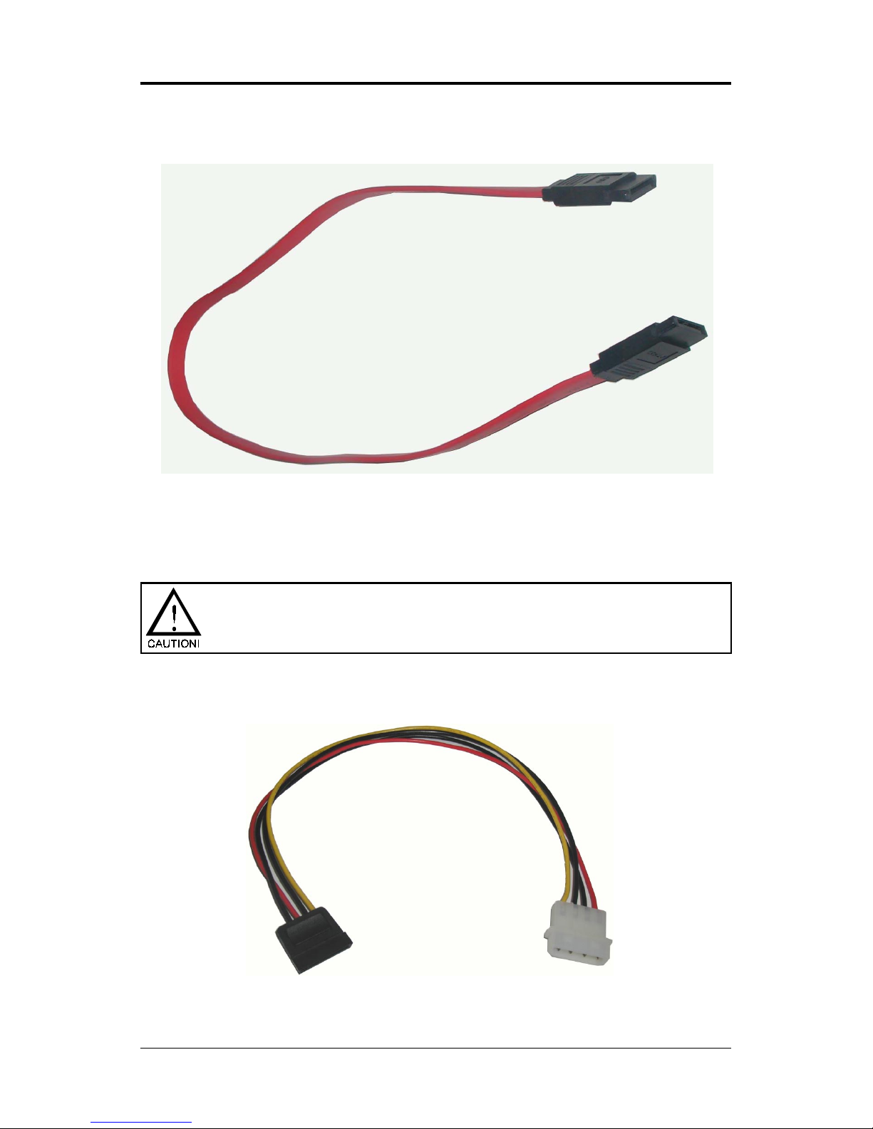
Serial ATA Cable
Please do not fold the serial ATA cable in a 90-degree angle, which
will cause the loss of data during the transmission.
Serial ATA Hard Disk Devices Power Cable(optional)
Connect one end of the SATA cable to the mainboard, and connect another
end to the SATA Hard Disk.
Page 25

25
PIN Assignment
1 MIC
2 GND
3 REF
4 POWER
5 AUD-OUT-R
6 AUD-RET-R
7 Reserved
8 Key(No pin)
9 AUD-OUT-L
10 AUD-RET-L
Front Panel Audio Header: FP-S1
This mainboard supports front panel microphone and speaker out ports.
If your computer case has these ports,connect them to FP-S1.
FP-S1
Note:
If you want to use “Front Audio” connector, you must remove 5-6,9-10 jumper.
In order to utilize the front audio header, your chassis must have front
audio connector. Also please make sure the pin assignment on the cable
is the same as the pin assignment on the MB header. To find out if the
chassis you are buying support front audio connector, please contract
your dealer.
FP-S1
10
9
2
1
Connectors
Page 26

26
Technical Reference Booklet
IEEE 1394 Connector:CN9 (optional)
The mainboard provides one 1394 pin headers that allow you to connect
IEEE 1394 ports.
1
210
CN9
9
Page 27

27
PIN SIGNAL
1TPA+
2TPA3 Ground
4 Ground
5 TPB+
6 TPB7 Cable power
8 Cable power
9 Key (no pin)
10 Ground
IEEE1394 Pin Definition
IEEE 1394 Cable (optional)
Connectors
Page 28

28
Technical Reference Booklet
USB Connectors: FP-U1/FP-U2
This mainboard has USB ports. Some computer cases have a special
module that mounts USB ports at the front of the case. If you have this kind
of case, use auxiliary USB connectors FP-U1/FP-U2 to connect the front
mounted ports to the mainboard.
PIN Assignment
1 VCC
2 VCC
3 USBP04 USBP15 USBP0+
6 USBP1+
7 GND
8 GND
9 KEY
10 OC#
FP-U1/FP-U2
10
9
2
1
FP-U2
10
9
2
1
FP-U1
Page 29

29
Front Panel Header: FP1
The mainboard provides one front panel connector.
FP1
NC
VCC
KEY
KEYLOCK
GND
IRRX
SPEAKER
GND
KEY
IRTX
NC
VCC
GND
KEY
GND
PWR_SW
RESET
NC
KEY
GND
PW_LED-
PW_LED+
HDD_LEDHDD_LED+
24 23
16
1718
20
22 21
19
15
13
7
11
9
5
3
1
14
6
8
10
12
2
4
Connectors
Page 30
30
Technical Reference Booklet
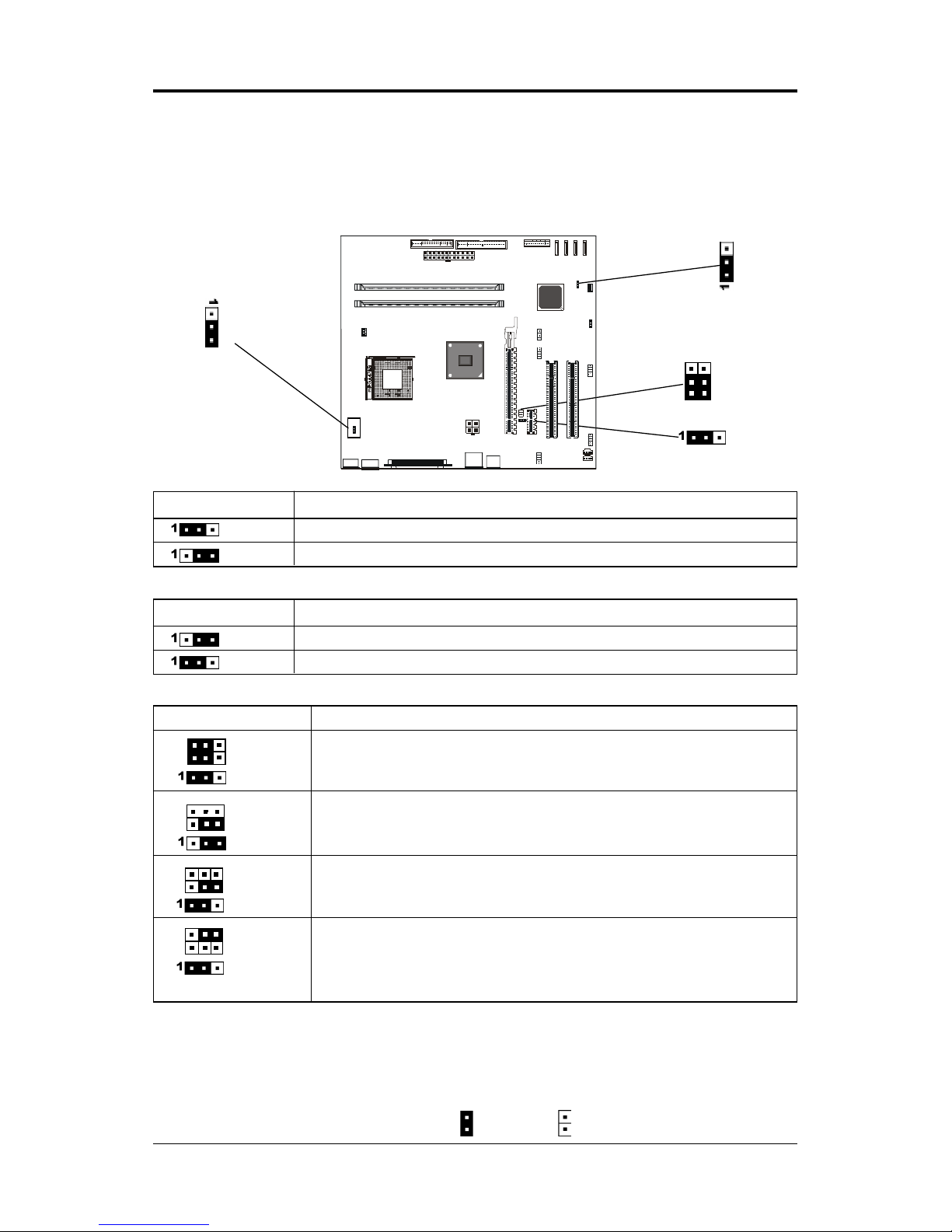
JP1 - CMOS Clear
JP1 Selection
1-2* Normal*
2-3 CMOS Clear
Keyboard Power Select Jumper: JP5
JP5 Select
2-3* Powered by +5V*
1-2 Powered by +5V Standby
CPU Frequency Jumper: JP2/JP21(optional)
Jumper Setting
This chapter explains how to configure the motherboard’s hardware.
Before using your computer, make sure all jumpers and DRAM modules are
set correctly. Refer to this chapter whenever in doubt.
Close Open * = Default setting.
JP1
JP5
1
2
JP2
1
2
1
1
2
JP2, JP21 CPU Frequency
(2-4)* Auto*
(1-3)*
(1-2)*
(OPEN) 100MHz (for FSB 100 CPU support)
(3-5)
(2-3)
OPEN 133MHz
(3-5)
(1-2)
(4-6) 200MHz
(OPEN)
(1-2)
JP21
1
2
2
Page 31

31
Slots
The motherboard provides one PCIEX16 slot , one PCIEX1 slots and two
32-bit PCI bus slots.
PCIEX16 Slot
PCI Slots
PCI (Peripheral Component Interconnect) Slots
The PCI slots allow you to insert the expansion cards to meet your needs.
When adding or removing expansion cards, make sure that you unplug the
power supply first. Meanwhile,read the documentation for the expansion card
to make any necessary hardware or software settings for the expansion card,
such as jumpers, switches or BIOS configuration.
PCIEX1 Slot
Connectors
Page 32

32
Technical Reference Booklet
CPU Installation
Please refer to the following steps to install the CPU.
1. Please turn off the power and unplug the power cord before installing the
CPU. Pull the lever sideways away from the socket. Make sure to raise the
lever up to a 90 degree angle.
2. Look for the gold arrow. The gold arrow should point towards the lever pivot.
The CPU can only fit in the correct orientation.
2. If the CPU is correctly installed, the pins should be completely embedded
into the socket and can not be seen. Please note that any violation of the
correct installation procedures may cause permanent damages to your
mainboard.
Page 33

33
4. Press the CPU down firmly into the socket and close the lever. As the CPU
is likely to move while the lever is being closed, always close the lever with
your fingers pressing tightly on top of the CPU to make sure the CPU is
properly and completely embedded into the socket.
5. Position the CPU cooler set onto the CPU.
CPU Installation
Page 34

34
Technical Reference Booklet
6. Use one end of the clip to hook the latch of the CPU sliding plate and then
hook the other three latch to fix the cooling fan set. At last, connect the fan to
the power supply connector provided on your mainboard.
When using Prescott CPU, It is recommended that the CPU heat
sink should be copper base and with fins radiated to all four
directions so that the CPU power generating area can be blown.
Page 35

35
Install DDR DIMMs
Please follow the following step to install DDR DIMMs.
1. Locate the DDR DIMM sockets.
2. Holding the DDR DIMM by the edges, remove it from its antistatic package.
3. Make sure the clips at either end of the socket are pushed away from the
socket.
4. Position the DDR DIMM above the socket. Align the two small notches in
the bottom edge of the DDR DIMM with the keys in the socket.
5. Insert the bottom edge of the DDR DIMM into the socket.
6. When the DDR DIMM is seated, push down on the top edge of the DDR
DIMM untilthe retaining clips at the ends of the socket snap into place.
Make sure the clips are firmly in place.
Please turn off system before installing and removing any
device, otherwise you’ll cause the system damage.
Clip
Clip
DDR DIMM
DDR DIMM Socket
Notch
Install DDR DIMMs
Page 36

36
Technical Reference Booklet
Memory Configurations
Single Channel Mode
• Single Channel Population
Examples:
• Non-identical DIMM or Non-Symmetrical Population
Examples:
Ch A
Ch B
Ch A Ch B
12
12
Note:
Memory channel speed determined by slowest DIMM populated in system.
Single Channel Mode with Single DIMM, Non-Symmetrical Population or
Non-Identical DIMMs.
Page 37

37
Dual Channel Mode
• Two DIMM Symmetrical Population
Examples:
• Symmetrical DIMMs must be identical for optimal performace
- Same DIMM density, eg 128MB, 256MB, 512MB, etc.
- Same DRAM Technology, eg 128M-bit.
- Same DRAM bus width, eg x8 or x16
- Single Side or Dual Side
DDR 1 DDR 2
12 12
Dual Channel Mode with Two Identical DIMMs Populated
Symmetrically.
DDR 1 DDR 2
Memory Configurations
Page 38

38
Technical Reference Booklet
BIOS Setup
This chapter discusses Award’s Setup Program built into the ROM BIOS. The Setup
Program allows users to modify the basic system configuration. This special information
is then stored in battery-backed RAM, which retains the setup information when the
power is turned off.
Starting Setup
The Award BIOS is immediately activated when you turn on the computer. The BIOS
reads the system information contained in the CMOS and begins the process of checking
out the system and configuring it. When it finishes, the BIOS will seek an operating
system on one of the disks and then launch and turn control over to the operating
system.
While the BIOS is in control, the Setup Program can be activated :
1. By pressing <Del> immediately after switching the system on, or
2. By pressing the <Del> key when the following message appears briefly at
the bottom of the screen during the POST (Power On Self Test )
Press DEL to enter SETUP
If the message disappears before you can respond and you still wish to enter Setup,
restart the system to try again by turning it OFF then ON or pressing the “RESET” button
on the system case. You may also restart by simultaneously pressing the <Ctrl>, <Alt>,
and <Delete> keys. If you do not press the keys at the correct time and the system does
not reset, an error message will be displayed and you will again be asked to ...
PRESS F1 TO CONTINUE, DEL TO ENTER SETUP
Getting Help
Press F1 to pop up a small help window that describes the appropriate keys to use and
the possible selections for the highlighted item. To exit the Help Window press <Esc> or
the F1 key again.
In Case of Problems
If, after making and saving system changes with the Setup Program, you discover that
your computer does not reset, use the Award BIOS defaults to override the CMOS
settings.
Page 39

39
Main Menu
Once you enter the Award BIOS CMOS Setup Utility, the Main Menu will appear on the
screen. The Main Menu allows you to select from various setup functions and two exit
choices. Use the arrow keys to select among the items and press <Enter> to accept and
enter the sub-menu.
Phoenix - Award WorkstationBIOS CMOS Setup Utility
8
Standard CMOS Features
8
Frequency/Voltage Control
8
Advanced BIOS Features Load Fail-Safe Defaults
8
Advanced Chipset Features Load Optimized Defaults
8
Integrated Peripherals Set Supervisor Password
8
Power Management Setup Set User Password
8
PnP/PCI Configurations Save & Exit Setup
8
PC Health Status Exit Without Saving
Esc : Quit ÏÐÎÍ : Select Item
F10 : Save & Exit Setup
Time, Date, Hard Disk Type ... ...
(Note : The figures of BIOS Setup Menu included here only show a typical
case, and may not be exactly the same as the one on your unit.)
Note that a brief description of each highlighted item will appear at the bottom of the
screen.
Standard This setup page includes all the items of Award™ special standard
CMOS Features features.
Advanced BIOS This setup page includes all the items of Award™ special enhanced
Features features.
Advanced This setup page includes all the items of chipset special features.
Chipset Features
Integrated This section page includes all the items of IDE hard drive and
Peripherals Programmed Input / Output features.
Power This entry only appears if your system supports Power
Management Management “Green PC” standards.
Setup
PNP/PCI This entry appears if your system supports PNP/PCI.
Configurations
PC Health Status Display CPU and Case Fan Speed etc.
Frequency/ CPU speed setting are settings of CPU speed. You should refer to
Voltage Control your CPU marking.
BIOS Setup
Page 40

40
Technical Reference Booklet
Load Optimized The chipset defaults are settings which provide for maximum
Defaults system performance. While Award has designed the
custom BIOS to maximize performance, the manufacturer
has the right to change these defaults to meet its needs.
Set Supervisor/ Changes, sets, or disables password. It allows you to limit
User Password access to the system and the Setup Program.
Save & Exit Saves value changes to CMOS and exits setup.
Setup
Exit Without Abandons all CMOS value changes and exits setup.
Saving
Standard CMOS Features
The items in Standard CMOS Setup Menu are divided into 10 categories. Each category
includes one or more setup items. Use the arrow keys to highlight the item and then use
the <PgUp> or <PgDn> key to select the desired value in each item.
Phoenix - Award WorkstationBIOS CMOS Setup Utility
Standard CMOS Features
Date (mm :dd :yy) Thu. Jan 01 2004 Item Help
Time (hh :mm:ss) 11 : 1 : 35
Menu Level
8
8
IDE Primary Master [Press Enter 4303 MB]
8
IDE Primary Slave [None] Change the day, month,
8
IDE Secondary Master [None] year and century
8
IDE Secondary Slave [None]
Drive A [1.44M, 3.5 in.]
Drive B [None]
Video [EGA/VGA]
Halt on [All, but keyboard]
Base Memory 640K
Extended Memory 30720K
Total Memory 31744K
ÏÐÎÍMove Enter: Select +/-/PU/PD : Value F10 : Save ESC : Exit F1 :General Help
F5 : Previous Values F6 : Fail-Safe Defaults F7 : Optimized Defaults
(Note : The figures of BIOS Setup Menu included here only show a typical
case, and may not be exactly the same as the one on your unit.)
Page 41

41
Date The date format is <day-of-the-week>. <month> <day> <year>.
Time The time format is <hour> <Minute> <second> displayed in
24-hour military-time clock. For example, 1 p. m. is displayed
as 13:00:00.
Primary These categories identify the types of the two channels that
Master/Primary have been installed in the computer.
Slave/Secondary
Master/Secondary If the controller of the HDD interface is SCSI, the selection shall
be “None”.
Drive A Type / This category identifies the types of floppy disk drive A or drive
Drive B Type B that has been installed in the computer.
Video The default setting is EGA/VGA.
Halt on You can select which type of error will cause the system to halt.
Advanced BIOS Features
This section allows you to configure your system for basic operation. You have the
opportunity to select the system’s default speed, boot-up sequence, keyboard operation,
shadowing and security.
Advanced Chipset Features
The Chipset Features Setup option is used to change the values of the chipset registers.
These registers control most of the system options in the computer.
This section allows you to configure the system based on the specific features of the
installed chipset. This chipset manages bus speeds and access to system memory
resources, such as DRAM and the external cache. It must be stated that these items
should not be altered. The default settings have been chosen because they provide the
best operating conditions for your system.
Integrated Peripherals
The Integrated Peripherals Setup allows the user to configure the onboard IDE controller,
floppy disk controller, the printer port and the serial ports.
Power Management Setup
The Power Management Setup Menu allows you to configure your system to most save
energy while operating in a manner consistent with your own style of computer use.
PNP/PCI Configurations
This section describes how to configure the PCI bus system. This section covers some
very technical items and it is recommended that only experienced users should make
any changes to the default settings.
PC Health Status
The PC Health Status display CPU and Case Fan Speed.
Frequency/Voltage Control
This section allows you to set CPU Speed.
BIOS Setup
Page 42

42
Technical Reference Booklet
Set Supervisor/User Password
You can set either supervisor or user password, or both of them. The difference
between them are:
Supervisor Password : You can enter the Setup Program and change
the options of the setup menus.
User Password : You can enter the Setup Program but can not
change the options of the setup menus.
When you select this function, the following message will appear at the center of the
screen to assist you in creating a password.
ENTER PASSWORD:
Type the password, up to eight characters in length, and press<Enter>. The new password
will clear the previously entered password from the CMOS memory. You will be asked to
confirm the password. Type the password again and press <Enter>. You may also
press <Esc> to abort the selection and operate without a password.
To disable a password, just press <Enter> when you are prompted to enter the password.
A message will be displayed to confirm that the password is disabled.
PASSWORD DISABLED.
Once the password is disabled, the system will reset and you can enter the Setup
Program freely.
When a password is enabled, you will be prompted to enter it every time you try to enter
setup. This prevents an unauthorized person from changing any setting of your system
configuration.
In addition, when a password is enabled, you can require the BIOS to request a password
every time your system is rebooted. This would further prevent unauthorized use of
your computer.
The password requirement is defined by the Security Option of the BIOS Features Setup
Menu. If the Security Option is set to “System”, the password will be required both at
resetting and at entering setup. If the option is set to “Setup”, the prompt only appears
when you try to enter setup.
Page 43

43
Flash Update Procedure
A program AWDFLASH.EXE is included in the utility diskette or CD (X:\Utility\
AWDFLASH.EXE). The user is recommended to follow the procedure below to update
the flash BIOS.
(X: your CD driver letter).
1. Create a DOS-bootable floppy diskette. Copy the new BIOS file (just obtained or
downloaded) and the utility program AWDFLASH.EXE to the diskette.
2. Allow the PC system to boot from the DOS diskette.
3. At the DOS prompt, key in
AWDFLASH
and hit <ENTER>
4. Enter the file name of the new BIOS.
5. The question: “Do you want to save BIOS (Y/N)?” is displayed.
Key in “N” if there is no need to save the existing BIOS content..
Key in “Y” if a backup copy of the existing BIOS is needed.
(A file name has to be assigned to the existing BIOS binary file.)
6. The message : “press“Y” to program or “N” to exit” is displayed.
Key in “Y”
7. Wait until the flash-update is completed.
8. Power down the PC system.
9. Restart the PC.
Warning:
DO not turn off or RESET the computer during the flash process.
If you are unsure how to upgrade the BIOS, it is best to take your
computer to an Authorized Service Center and have a trained
technician do the work for you.
BIOS Setup
Page 44

44
Technical Reference Booklet
0184A8
APPENDIX
Note to User:
The bundled driver CD attached an Auto-Run feature for all the drivers
that the motherboard need. Please select the drivers that you want
to install and click the button on the installation panel.
 Loading...