

Page 1

s
WIRING DIAGRAM 2008 SUPPLEMENT
VOLVO V70 (08-), XC70 (08-) & S80 (07-)
TP 39127202 LATE DESIGN
Page 2

© Volvo Car Corporation
Vehicles with SRS (Airbag)/SIPS bag/
IC (Inflatable curtain)
Warning!
Extra caution must be exercised when working on vehicles equipped with SRS/SIPS bag/IC
in order to avoid:
1. Personal injuries when performing repair work.
2. Damage or malfunction of the SRS/SIPS bag/IC system.
Work involving the SRS/SIPS bag/IC systems or other components in the vehicle that may
affect the SRS/SIPS bag/IC systems must always be performed by an authorized Volvo
workshop.
In case of doubt, consult the SRS and SIPS bag/IC service manual.
Is the vehicle equipped with SRS/SIPS bag/IC?
Vehicles with SRS are most easily recognized by the letters SRS in the center of the steering
wheel. If the vehicle also has a passenger side airbag, the letters SRS are stamped on the
dashboard above the glove compartment. SRS vehicles from 1993 and onward also have
explosive seat belt tensioners. SIPS bags are only installed on SRS vehicles from 1995 and
onward. SIPS bag decals are located on the windshield and seat compartment. Vehicles with
IC can be recognized by the letters IC on the C/D panel (4 door) or the B panel (5 door).
General recommendations
• Be especially careful when working on or around SRS, SIPS, and IC components.
• Make sure that no wires are pinched, frayed, or pierced.
• Never fit accessories by the sensors.
• Where applicable, work on the steering wheel, steering shaft, or steering gear must be done
in accordance with the methods in the SRS section of VIDA.
• Certain components of the aforementioned systems must be grounded while working. Read
the appropriate sections in VIDA.
• Install no accessories in the areas between the A and B-posts, the B and C-posts, and the
C and D-posts.
Test terminal
Fuse in cargo compartment auxiliary fuse box.
Changes introduced up to and including September 2007
Any changes made to the vehicle after this date are not included in the
manual. If necessary, refer to service bulletins.
Volvo models are sold in versions adapted for different markets. These
adaptations depend on factors such as legal requirements, taxation, and
market demands.
This manual may therefore include illustrations and text that do not apply to
the vehicles in your country .
Order number: TP 39127202
TP 39127202 Supplement, can also be found on Electronic Wiring Diagram
(EWD) TP 39125002. TP39127202 contains updated information for the
2008 model late design, for other electrical systems see publication
TP39115202.
We retain the right to make modifications.
Page 3

TP39127202 V70(08-), XC70(08-) & S80(07-) 2008 Supplement 3
Vehicles with SRS (Airbag)/SIPS bag/
IC (Inflatable curtain) ................... .................................. 2
Explanations................................... ............................... 5
Abbreviations............................................. ... ................. 5
How to use the wiring diagrams 1:2............................... 6
Electrical distribution 1:2................................................ 8
Fuses
Engine compartment electrical center F1-F7................10
Engine compartment distribution box F9-F24...............11
Engine compartment distribution box F25-F30.............12
Engine compartment distribution box F31-F37.............13
Engine compartment distribution box F38....................14
Engine compartment electrical center F39-F44............ 15
Central Electronic Module (CEM) F1 - F11...................16
Central Electronic Module (CEM) F13 - F19.................17
Central Electronic Module (CEM) F20 - F28.................18
Rear electrical center FA1-FA12..................................19
Distribution box in cargo compartment FB1-FB12........20
Rear electrical center FD1-FD7....................................21
Battery PF1-PF2................................................. .. ........22
Relays
Relays in the engine compartment R2......................... 23
Relays in the engine compartment R8-R9................... 24
Relays in the engine compartment R10-R13............... 25
Distribution box in cargo compartment RA1-RD1........ 26
Central Electronic Module (CEM)................................ 27
Ground connections
Overview...................................................................... 28
31/1 - 31/7 ................................................................... 29
31/10 - 31/15 ............................................................... 30
31/47 - 31/66 ............................................................... 31
31/67 - 31/83 ............................................................... 32
31/84 - 31/93 ............................................................... 33
31/94 - 31/XX10........................................................... 34
31/XX14 - 31/AL.......................................................... 35
Control modules
Overview of locations................................................... 36
Overview designations................................................. 37
Data communication high speed CAN......................... 38
Data communication high speed CAN 4 Cyl................ 39
Data communication LIN 1:2 ....................................... 40
Data communication MOST......................................... 42
Group 23 Fuel system
Engine management system, 5 Cyl. Diesel 1:3........... 43
Engine management system, 4 Cyl. 1:2...................... 46
Engine management system, 4 Cyl. Flexifuel 1:2........ 48
Engine management system, 4 Cyl. Diesel 1:2........... 50
Engine management system, 6 Cyl. Turbo 1:2............ 52
Engine management system, 8 Cyl. 1:2...................... 54
Emission control, 4 Cyl................................................ 56
Emission control, 8 Cyl................................................ 57
Group 26 Cooling system
Cooling fan, 4 Cyl. ....................................................... 58
Cooling fan, 4 Cyl. Diesel............................................. 59
Cooling fan, 5 Cyl. Diesel............................................. 60
Cooling fan, 5 Cyl. Turbo & 6 Cyl................................. 61
Cooling fan, 8 Cyl. ....................................................... 62
Group 27 Engine controls
Cruise control 4 Cyl.......................................................63
Cruise control 4 Cyl. Diesel...........................................64
Cruise control 5 Cyl. & 6 Cyl.........................................65
Cruise control 5 Cyl. Diesel...........................................66
Cruise control 8 Cyl.......................................................67
Group 32 Alternator and voltage regulator
Power supply ............................................................... 68
Group 33 Starting system
Starting system 4 Cyl................................................... 69
Group 35 Lighting
Running/parking lights, Tail lights V70......................... 70
Running/parking lights, Tail lights (Bi-Xenon) V70....... 71
Fog lights, V70............................................................. 72
Brake light, V70 ........................................................... 73
Reversing lights, V70................................................... 74
Door handle lighting LHD............................................. 75
Door handle lighting RHD............................................ 76
Group 36 Other electrical equipment
Direction indicator and Hazard warning flashers
LHD, V70 ..................................................................... 77
Direction indicator and Hazard warning flashers
RHD, V70..................................................................... 78
High-pressure headlight washer.................................. 79
Wiper/washer rear window, V70 .................................. 80
Parking assistance....................................................... 81
Keyless vehicle 4 Cyl. 1:2............................................ 82
Collision warning with brake servo............................... 84
Alcolock ....................................................................... 85
Table of Contents 1:2
Page 4

TP39127202 V70(08-), XC70(08-) & S80(07-) 2008 Supplement 4
Group 37 Wiring and fuses, Accessories
Tow hitch cable harness, 4-pin V70............................. 86
Tow hitch cable harness, 7-pin V70............................. 87
Tow hitch cable harness, 13-pin V70........................... 88
Group 38 Instruments
Driver information module............................................ 89
Group 39 Other
Audio 1:2 ..................................................................... 90
Audio Premium 1:3...................................................... 92
Rear seat entertainment.............................................. 95
Group 43 Transmission
Differential Electronic Module (DEM)........................... 96
Group 55 Parking brake
Electronic parking brake.............................................. 97
Group 87 Climate control system
Climate control system 4 Cyl. 1:2................................ 98
Connectors............................................... 100
Branching points .....................................112
Cable harness routing in vehicle
Engine harness, 4 Cyl.................................................117
Engine harness, 4 Cyl. Diesel.....................................117
Engine harness, 8 Cyl.................................................118
Harness engine compartment.....................................118
Harness ceiling ...........................................................119
Harnesses rear axle....................................................119
Component illustrations..........................120
Index..........................................................124
List of components 1:4............................125
Table of Contents 2:2
Page 5

TP39127202 V70(08-), XC70(08-) & S80(07-) 2008 Supplement 5
Explanations
Abbreviations
Groups
Group 23 = Fuel system
Group 26 = Cooling system
Group 27 = Engine controls
Group 32 = Alternator and voltage regulator
Group 33 = Starting system
Group 35 = Lighting
Group 36 = Additional electrical equipment
Group 37 = Wiring and fuses
Group 38 = Instruments
Group 39 = Other
Group 43 = Transmission
Group 55 = Parking brake
Group 87 = Climate control system
Ignition switch symbols
X = Accessories (audio position)
S = Powered upon insertion of key
15 = Contact remains connected during
start
15l = Contact is broken while starting
30 = Constant power from the battery
50 = Start
Countries/Markets
A = Austria
AUS = Australia
B = Belgium
CDN = Canada
CH = Switzerland
D = Germany
DK = Denmark
E= Spain
EU/OS = Markets outside USA and Canada
FIN = Finland
GB = Great Britain
ISR = Israel
J = Japan
KOR = Korea
N= Norway
NL = Netherlands
S = Sweden
USA = United States of America
WEU = Western Europe
Other
ACC = Adaptive Cruise Control
AUTO = Automatic transmission
BLIS = Blind spot information system
CAN = CAN communication
DPY = Display
ECC = Electronic climate control system
ETA = Engine throttle body
GDL = Gas discharge lamp
HISPEED = High speed data bus
IR = Infrared sensor
LIN = LIN communication
LH = Left-hand side
LHD = Left-hand drive
MAN = Manual transmission
MEMORY = Memory driver’s seat
MIDSPEED = Midspeed data bus
MMS = Mass Movement Sensor
PETROL = Gasoline
RH = Right-hand side
RHD = Right-hand drive
SCR = Screened
SRS = Airbag
T = Turbocharged engine
W/O = Without
2WD = Two-wheel drive
4CYL, I4 = 4-cylinder engine
5CYL, I5 = 5-cylinder engine
6CYL, I6 = 6-cylinder engine
8CYL, V8 = 8-cylinder engine
Colors
BK, SB = Black
BN = Brown
BU, BL = Blue
GN = Green
GY, GR = Gray
LGN = Light Green
NL = Natural
OG, OR = Orange
PK, P = Pink
RD, R = Red
VT, VO = Violet
WH, W = White
YE, Y = Yellow
Page 6

TP39127202 V70(08-), XC70(08-) & S80(07-) 2008 Supplement 6
The descriptions below apply in general
to all wiring diagram manuals, although
not all sections are necessarily contained in this manual.
How to use the wiring diagrams 1:2
A. Component designation
Every component has a component designation that
consists of two parts.
The first part is a type number that describes the
type of component in question, for example 3/xx.
The second part of the designation is a serial number, e.g. x/2.
Together, this constitutes a component designation,
e.g. 3/2.
At the end of the manual is a list of components,
where, with the help of the component designation,
you can read off the name of the component, for
example, 3/2 = light switch.
List of type numbers
The list shows which type of component that respective type numbers refer to, for example, 3/x = switch,
6/x = electric motor, etc.
1 Battery
2Relay
3 Switch
4 Control module
5 Driver information module
6 Electric motor
7Sensor
8 Actuator
9 Heatin g element
10 Light
11 Fuse
15 Electrical distribution rail/box
16 Audio
17 Service/diagnostics
18 Contact reel
19 Meter
20 Ignition component/shunt
27 Optics
31 Ground connection
73 Branching point
74 Connector
B. Branching points
The wiring diagrams contain numbered branching
points, for example 73/5035.
This manual contains a section with a list of branching points. This list shows all the components that
are connected to each branching point.
The location of the branching points is shown in the
"Cable harness routing in vehicle" section.
C. Connectors
Connectors provide a bridge between two cable harnesses and are described in the
"Connectors" section.
D. Electrical distribution
Operation of the fuses and relays is shown in the
"Electrical distribution" section.
E. Data communication
Today’s cars contain CAN, LIN and MOST networks
that transfer information. Connections to these networks are not shown in their entirety in the respective wiring diagram. Complete information on CAN,
LIN and MOST communication is found in the section "Control modules".
F. Abbreviations
A number of different abbreviations are used in the
manual. These are explained in the section "Abbr eviations".
G. Component location
The end of the manual contains a section that
describes component appearance and location in
numerical order.
Page 7

TP39127202 V70(08-), XC70(08-) & S80(07-) 2008 Supplement 7
How to use the wiring diagrams 2:2
List of symbols
= System voltage
= Ground connection via wiring
= Ground connection in compo-
nent/chassis
= Screened wire
= Junction point
= Twisted cable
= Electrical connection
= Variant
= CAN communication
= CAN high data signal (CAN H)
= CAN low data signal (CAN L)
= LIN communication
= LIN communication
= DIN cable, coaxial cable, etc.
= Data communication
= CAN communication
= MOST communication
= MOST communication
= Connection with distribution box
= Further connection to...
= Connector between cable har-
nesses
= Connector connected in component
LIN
CAN
1
1
G
A
DEC
F B
10/17
LIN
C1:50
C1:49
30+
1
CEM
4/56
2
11A/1211A/2
C2:24
1
1
2
11B/23
15/31
C2:50
RD-BK
RD-BU
BK
BK
BK
BK
RHD
LHD
3
5
REV
GND
10/51
10/52
10/44
10/45
C5:2
C5:1
C1:10
C1:40
C3:52
31/8331/9331/9431/47
GN-OG
GY-RD
YE-BK
VT-GN
CAN
10/3 10/18 10/17
2
1
4
74/601
1
74/601
73/5105
BK-OG
BK-OG
BK-OG
BK-BU
BN-BU YE-VT
C2:52
73/3033
73/4017
73/4016
73/3035
BK-OG
BK-VT
BK-OG
BK-VT
POSFOGSTOPTURN
5
REV
GND
POS FOG STOP TURN
3
31/48
73/5033
BK-BU BK-BU
1
6
5
LIN
RD-BK
RD-BK
GN-VT
3/111
74/411
12
LSM
CAN
6
2
5/1
DIM
10/1
TURN POS HIGH LOW
1
10 10
M
10/2
TURN POS HIGH LOW
M
1
Page 8

TP39127202 V70(08-), XC70(08-) & S80(07-) 2008 Supplement 8
Electrical distribution 1:2
Overview, Electrical center and Cold zone in engine compartment
2
1
3
5
2/193
R9
15/31
15/33
11B/26
21
11B/25
21
11B/24
21
11B/36
21
11B/37
21
11B/38
21
11B/41
11B / 1 8
12
11B / 1 6
12
11B / 1 7
73/3068
73/3085
12
11B / 1 9
12
1
1B/20
12
1
1B/21
12
1
1B/22
12
11B / 2 3
12
11B / 2 8
12
11B / 2 9
12
RD-VT
RD-VT
RD-VT
RD
RD
RD
RD
GY-BK
RD
RD
GN-VT
RD-BK
RD_BU
RD-GN
RD-GY
RD-BN
15/32
15/32
15/32
4/56C5:2
4/56C5:1
RD
RD
RDRD
RD
RD
RD
RD-GY
VT-GN
4/56C1:48
RD
RD
RD
RD
RD
RD
RD
RD-BU
RD
RD
RD
GY-VT
GY-VT
GY-VT
GY-VT
RD
RD-BK
RD
11B /27
12
11A/1
11A/2
11A/3
11A/4
11A/5
11A/6
12
11A/7
12
12
12
12
12
12
21
11B/40
21
11B/39
21
11A/43
21
11A/42
21
11A/44
21
11B/15
21
11B/33
21
11B/32
21
11B/31
21
11B/30
21
11B/35
21
11B/34
21
2
1
3
5
2/22
R13
2
1
3
5
2/239
R11
2
1
3
5
2/31
R8
2
1
3
5
2/32
R10
2
1
3
5
2/17
R2
2
1
3
5
2/35
R12
11B /13
11B /11
11B/9
11B /12
11B /10
12
11B /14
12
12
12
12
12
11B/8
12
73/3076
6/25
31
M
ACM
30
C1:1
6/26
B+
31
G
C1:1
12V
BK
31/3
1/1
PF1
PF2
2
1
1
2
LIN
9/42
4/56C1:45
4/56C1:65
73/3041
RD
RD-VT
4/46B:16 5&6CYL.
4/46B:54 8CYL.
{
RD
W/O 5CYL.D
& 4CYL.P
8 CYL.
4 CYL.D
4/46C2:G4 4
CYL.D
2/14
(4 Cyl.Diesel)
2/32
(4 Cyl.Diesel)
(8 Cyl.)
Page 9

TP39127202 V70(08-), XC70(08-) & S80(07-) 2008 Supplement 9
Electrical distribution 2:2
Overview, rear electrical center
73/5040
11D/A7
21
11D/A6
21
11D/A5
21
11D/A8
21
11D/A3
21
11D/A2
21
11D/A1
21
11D/A4
21
11D/A10
21
11D/A9
21
11D /A11
21
11D/A12
21
73/5069
2
1
3
5
2/75
2/82
15/32
15/31
RA2
2
1
3
5
A
BK NL
BU
B
D
RA1
11D/B3
12
2
11D/B2
12
11D/B1
12
11D/B4
1
YE-VT
YE-VT
BU-RD
BU-RD
RD-BN
BU-RD
RD-GY
RD-GY
RD-GY
RD-GY
RD-GY
R
D
-G
Y
R
D
-G
Y
11D/B7
12
11D/B6
12
11D/B5
12
11D/B8
12
11A/5
12
11A/3
12
11A/4
30+
74/504B
12
RD-GN
RD-GN
RD-BN
RD-GN
RD-GN
RD-GN
RD-GN
RD-VT
RD-VT
11D/B9
12
11D/B10
12
11D/B11
12
11D/B12
12
11D/D8
12
11D/D9
12
11D/D10
12
11D/D11
12
11D/D12
12
2
1
3
5
RB2
2
1
3
5
2/88
RB1
11D/D3
12
11D/D2
12
11D/D1
12
11D/D4
12
11D/D7
12
11D/D6
12
11D/D5
12
2
1
3
5
RD1
2
1
3
5
4
RD2
1
74/505
2
73/5075
1
RD-GN
2/16
V70
RD-BN
Page 10

TP39127202 V70(08-), XC70(08-) & S80(07-) 2008 Supplement 10
1
2
3
4
5
6
7
Fuses
Engine compartment electrical center F1-F7
15/31 Engine compartment electrical center
No. No. Fuse function via A
F1 11A/1 Main fuse for fuses in CEM 4/56 50
F2 11A/2 Main fuse for fuses in CEM 4/56 50
F3 11A/3 11D/A1-11D/A12 Fuses in cargo compartment 15/32 - 60
F4 11A/4 11D/B1-11D/B12 Fuses in cargo compartment 15/32 - 60
F5 11A/5 11D/D1-11D/D7 Fuses in cargo compartment 15/32 - 50
F7 11A/7 9/42 PTC-element - 100
continues
Page 11

TP39127202 V70(08-), XC70(08-) & S80(07-) 2008 Supplement 11
39
40
41 38
37
36
34
35
32
33
30
25
22
19
15
16
17
20
23
26
28
18
21
2427
29
31
42
4344
14 13 12
89
1011
Fuses
Engine compartment distribution box F9-F24
15/31 Engine compartment distribution box
No. No. Fuse function via A
F9 11B/9 6/1 Wiper Motor Module (WMM) - 30
F10 11B/10 4/7 Combustion Preheater Module (CPM) 25
F11 11B/11 4/31 Fan control module
6/28 Motor, passenger compartment fan
-
-
40
F13 11B/13 4/16 Brake Control Module (BCM), pump - 40
F14 11B/14 4/16 Brake Control Module (BCM), valves - 20
F16 11B/16 4/118 Headlamp Control Module (HCM)
10/1 Lamp housing, front left
10/2 Lamp housing, front right
-
-
-
10
F17 11B/17 F2-F4 Fuses in the Central Electronic Module (CEM) - 20
F18 11B/18 4/80 Forward Sensing Module (FSM)
7/203 Forward-aimed radar (FLR)
-
-
5
F19 11B/19 4/99 Electronic power steering control module - 5
F20 11B/20 4/28 Transmission Control Module (TCM)
4/46 Engine Control Module (ECM)
4/9 Supplemental Restraint System Module (SRS)
-
-
-
10
F21 11B/21 9/43 Heated windshield washer nozzle, left
9/44 Heated windshield washer nozzle, right
-
-
10
F22 11B/22 6/114 Vacuum pump, 5 Cyl. T. 8/84 20
F23 11B/23 3/111 Light Switch Module (LSM) - 5
F24 11B/24 6/104 High pressure headlight washer motor - 15
continues
Page 12

TP39127202 V70(08-), XC70(08-) & S80(07-) 2008 Supplement 12
39
40
41 38
37
36
34
35
32
33
30
25
22
19
15
16
17
20
23
26
28
18
21
2427
29
31
42
4344
14 13 12
89
1011
Fuses
Engine compartment distribution box F25-F30
15/31 Engine compartment distribution box
No. No. Fuse function via A
F25 11B/25 9/1 Front 12V outlet
9/25 Rear 12V outlet
16/45 Portable navigation system
16/109 DVD player/control module
-
-
-
-
15
F26 11B/26 3/117 Switch unit, ceiling light
4/33 Sunroof control module
6/48 Damper Motor Module (DMM), recirculation
6/95 Damper Motor Module (DMM), temperature, left side
6/96 Damper Motor Module (DMM), temperature, right side
6/102 Damper Motor Module (DMM), defroster
6/103 Damper Motor Module (DMM), floor/ventilation
7/159 Air Quality Sensor (AQS)
16/159 Control module, mobile phone handsfree
-
3/112
3/112
3/112
3/112
3/112
3/112
-
5
F27 11B/27 2/31 Relay, 15-feed
2/193 Relay, comfort functions
-
-
5
F28 11B/28 2/64 Relay auxiliary lights
10/65 Auxiliary light, front right
10/69 Auxiliary light, front left
-
2/64
2/64
20
F29 11B/29 2/17 Relay, horn
16/10 Horn 1
16/11 Horn 2
-
2/17
2/17
15
F30 11B/30 2/32 Main relay, engine management system
4/46 Engine Control Module (ECM), not Diesel
-
-
10
continues
Page 13

TP39127202 V70(08-), XC70(08-) & S80(07-) 2008 Supplement 13
39
40
41 38
37
36
34
35
32
33
30
25
22
19
15
16
17
20
23
26
28
18
21
2427
29
31
42
4344
14 13 12
89
1011
Fuses
Engine compartment distribution box F31-F37
15/31 Engine compartment distribution box
No. No. Fuse function via A
F31 11B/31 4/28 Transmission Control Module (TCM) - 15
F32 11B/32 8/3 Electromagnetic clutch, climate control system 2/22 15
F33 11B/33 2/14 Relay, glow plug control system, 4 Cyl. Diesel
2/22 Relay, climate control system
2/239 Relay, coolant pump, 8 Cyl.
-
-
-
5
F34 11B/34 6/25 Starter motor 2/35 30
F35 11B/35 20/3-8 Spark plug with ignition coil, 5, 6 & 8 Cyl.
20/12-13 Spark plug with ignition coil, 8 Cyl.
-
-
20
20/3-6 Spark plug with ignition coil, 4 Cyl.
20/22-26 Glow plug, 5 Cyl. Diesel
8/82 Solenoid variable turbo ge ometry, 4 Cyl. Diesel
8/132 Control valve intake, 4 Cyl. Diesel
4/109
-
-
10
F36 11B/36 6/120 Engine throttle body 4/46 10
4/46 Engine Control Module (ECM), 4, 6, 8 Cyl. & Diesel
6/118 Control motor swirl duct throttle, 5 Cyl.
6/120 Electronic throttle actuator , 5 Cyl.
8/111 Control valve fuel flow
8/98 Control valve fuel pressure, 5 Cyl.
-
4/46
4/46
4/46
4/46
15
F37 11B/37 4/46 Engine Control Module (ECM), 6 Cyl. & 5 Cyl. Diesel
8/6-11 Injection valves
8/115 Injector
8/116 Injector
7/17 Mass air flow sensor (MAF)
-
-
-
-
-
15
continues
Page 14

TP39127202 V70(08-), XC70(08-) & S80(07-) 2008 Supplement 14
Fuses
Engine compartment distribution box F38
39
40
41 38
37
36
34
35
32
33
30
25
22
19
15
16
17
20
23
26
28
18
21
2427
29
31
42
4344
14 13 12
89
1011
15/31 Engine compartment distribution box
No. No. Fuse function via A
F38 11B/38 6/99 Motor EGR, 4 Cyl.
8/45 Vacuum valve variable intake manifold, 4 Cyl.
8/114 Mixing valve, air/fuel, 4 Cyl.
-
-
-
10
8/77 Control valve fuel volume, 4 Cyl. Diesel
8/133 Control valve fuel pressure, 4 Cyl. Diesel
-
-
8/3 Electromagnetic clutch climate control system, 5 Cyl. T.
8/28 Turbocharger control valve, 5 Cyl. T.
8/81 Solenoid, variable valve timing, exhaust, 5 Cyl. T.
8/117 Solenoid, variable valve timing, intake, 5 Cyl. T.
-
-
-
-
6/143 Control motor, turbo, 5 Cyl.
8/3 Electromagnetic clutch climate control system, 5 Cyl.
8/113 Bypass valve, EGR cooling, 5 Cyl.
8/120 EGR valve, 5 Cyl.
-
-
-
-
4/46 Engine Control Module (ECM), 6 Cyl.
6/139 Upper actuating motor, intake manifold, 6 Cyl.
6/140 Lower actuating motor, intake manifold, 6 Cyl.
8/3 Electromagnetic clutch climate control system, 6 Cyl.
8/117 Solenoid, variable valve timing, intake, 6 Cyl.
8/125 Solenoid front cam profile, 6 Cyl.
8/126 Solenoid rear cam profile, 6 Cyl.
-
-
-
-
-
-
-
4/46 Engine Control Module (ECM), 8 Cyl.
8/3 Electromagnetic clutch climate control system, 8 Cyl.
8/19 Solenoid, variabl e valve timing, intake, bank 2, 8 Cyl.
8/81 Solenoid, variable valve timing, exhaust, bank 2, 8 Cyl.
8/117 Solenoid, variable valve timing, intake, bank 1, 8 Cyl.
8/118 Solenoid, variable valve timing, exhaust, bank 1, 8 Cyl.
-
-
-
-
-
-
continues
Page 15

TP39127202 V70(08-), XC70(08-) & S80(07-) 2008 Supplement 15
39
40
41 38
37
36
34
35
32
33
30
25
22
19
15
16
17
20
23
26
28
18
21
2427
29
31
42
4344
14 13 12
89
1011
Fuses
Engine compartment electrical center F39-F44
15/31 Engine compartment distribution box
No. No. Fuse function via A
F39 11B/39 7/15 Heated oxygen sensor, front, 5 Cyl. T.
7/103 Rear heated oxygen sensor, 5 Cyl. T.
8/18 EVAP valve, 5 Cyl. T.
-
-
-
15
7/15 Front oxygen sensor, bank 1, 6 Cyl.
7/82 Rear oxygen sensor, bank 1, 6 Cyl.
7/103 Front oxygen sensor, bank 2, 6 Cyl.
7/104 Rear oxygen sensor, bank 2, 6 Cyl.
8/18 EVAP valve, 6 Cyl.
-
-
-
-
-
7/15 Front oxygen sensor, bank 2, 8 Cyl.
7/82 Front oxygen sensor, bank 1, 8 Cyl.
7/103 Rear oxygen sensor, bank 2, 8 Cyl.
7/104 Rear oxygen sensor, bank 1, 8 Cyl.
8/107 Variable intake valve, 8 Cyl.
8/118 Solenoid, variable valve timing, exhaust, bank 1, 8 Cyl.
-
-
-
-
-
-
7/15 Heated oxygen sensor, front, 5 Cyl. T., Diesel - 10
F40 11B/40 9/32 PTC resistor, crankcase ventilation, 5 Cyl.
9/38 Heated fuel filter, 5 Cyl.
9/47 PTC resistor crankcase ventilation in hose, 5 Cyl. Diesel
-
-
-
20
6/73 Coolant pump, 8 Cyl. 2/239 10
F41 11B/41 6/67 Pump fuel leakage control, not 4 & 5 Cyl. - 5
F42 11A/42 20/22-26 Glow plug, 5 Cyl. 4/109 70
20/22-25 Glow plug, 4 Cyl. 2/14 60
F43 - - -F44 11A/44 4/71 Cooling fan control module - 60
4/71B Twin cooling fan contro l mo du l e - 80
Page 16

TP39127202 V70(08-), XC70(08-) & S80(07-) 2008 Supplement 16
1 2 3 4 5 6
7 8 9 10 11
12 13
14
15 16 17 18 19 20
21 22 23 24 25
26 27 28
Fuses
Central Electronic Module (CEM) F1 - F11
4/56 Central Electronic Module (CEM)
No. Fuse function via A
F1 7/149 Rain Sensor Module (RSM) 4/56 5
F2 4/9 Supplemental Restraint System Module (SRS)
7/93 Occupant Weight Sensor (OWS)
-
-
10
F3 4/16 Brake Control Module (BCM) - 5
F4 3/65 Switch, heated rear seat
7/51 Accelerator pedal sensor
8/48 Auto-dimming rearview mirror
9/42 PTC-element
-
-
-
-
7.5
F6 3/281 Infotainment Control Module (ICM)
16/1 Integrated Audio Module (IAM)
16/109 DVD player/control module
4/124 Accessory USB unit (AUU)
-
-
-
-
15
F7 3/4 Steering wheel switch left (SWSL)
3/131 Steering wheel switch right (SWSR)
3/135 RTI switch
3/130
3/130
3/131
7.5
F9 10/1 Lamp housing, front left
10/2 Lamp housing, front right
K2
K2
15
F10 4/33 Sunroof Module (SRM) - 20
F11 10/48 Right-hand reversing light
10/55 Left-hand reversing light
K3
K3
7.5
continues
Page 17

TP39127202 V70(08-), XC70(08-) & S80(07-) 2008 Supplement 17
1 2 3 4 5 6
7 8 9 10 11
12 13
14
15 16 17 18 19 20
21 22 23 24 25
26 27 28
Fuses
Central Electronic Module (CEM) F13 - F19
4/56 Central Electronic Module (CEM)
No. Fuse function via A
F13 10/5 Fog light, front left
10/6 Fog light, front right
K1
K1
15
F14 6/127 Washer motor K5A, K5B 15
F15 4/80 Forward Sensing Module (FSM) - 10
F17 3/27 Switch unit, power passenger seat
3/176 Switch, driver’s door power window
3/291 Tailgate closing switch
4/76 Remote control unit for garage door opener
10/25 Ceiling light, cargo compartment, V70
10/29 Glove compartment lighting
10/114 Left-hand vanity mirror lighting
10/115 Vanity mirror lighting , righ t
10/125 Left-hand front courtesy lighting
10/126 Right-hand front courtesy lighting
10/127 Lighting, cargo compartment, left-hand side, S80
10/128 Lighting, cargo compartment, right-hand side, S80
10/150 Rear reading light
26/5 DC/AC converter, fuel tank
26/6 Converter/control module, sill moldings, driver’s side
26/7 Converter/control module, sill moldings, passenger side
-
-
-
-
-
-
-
-
-
-
-
-
-
-
-
-
7.5
F18 5/1 Driver Information Module (DIM) - 5
F19 4/52 Power Seat Module (PSM) - 5
continues
Page 18

TP39127202 V70(08-), XC70(08-) & S80(07-) 2008 Supplement 18
1 2 3 4 5 6
7 8 9 10 11
12 13
14
15 16 17 18 19 20
21 22 23 24 25
26 27 28
Fuses
Central Electronic Module (CEM) F20 - F28
4/56 Central Electronic Module (CEM)
No. Fuse function via A
F20 6/32 Rear window wiper motor, V70 2/16 15
F21 4/119 Signal receiver, keyless vehicle (RKE)
4/119.2 Remote Receiver Module (RRX)
7/199 Ultrasonic sensor (IMS)
7/214 Heartbeat sensor
-
-
-
-
5
F22 6/33 Fuel pump K8, 4/83 20
F23 4/102 Steering Column Lock Module (SCL) K9 20
F25 K6-B Relay, soldered
K12 Relay, soldered
3/78 Lock unit, tailgate V70
6/8 Lock motor central locking, trunk lid/tailgate, S80
6/37 Lock motor, fuel filler cover
-
K6-B
K6-B
K12
10
F26 4/6 Climate Control Module (CCM)
16/35 Siren Control Module (SCM)
17/13 Data link connector
-
-
-
5
F27 3/132 Start Control Module (SCU) - 5
F28 4/93 Keyless Vehicle Module (KVM)
10/19 Auxiliary brake light
10/43 Right brake light
10/50 Left brake light
3/9
3/9, 4/56
3/9, 4/56
3/9, 4/56
5
Page 19

TP39127202 V70(08-), XC70(08-) & S80(07-) 2008 Supplement 19
9
10
11
12
5
6
7
8
1
2
3
4
Fuses
Rear electrical center FA1-FA12
15/32 Rear electrical center
No. No. Fuse function via A
FA1 11D/A1 3/126 Driver Door Module (DDM) - 25
FA2 11D/A2 3/127 Passenger Door Module (PDM) - 25
FA3 11D/A3 3/128 Rear left Door Module (LDM) - 25
FA4 11D/A4 3/129 Rear Right Door Module (RDM) - 25
FA6 11D/A6 9/24 Refrigeration box
17/19 12V outlet, cargo compartment
2/141
-
15
FA7 11D/A7 2/82 Relay, heated rear wind ow
9/2 Rear window defroster
-
2/82
30
FA8 11D/A8 8/59 Rear left head restraint solenoid, S80
8/60 Rear right head restraint solenoid, S80
2/75
2/75
15
FA9 11D/A9 17/39 13-pin outlet, tow hitch cable harness - 15
FA10 11D/A10 4/52 Power Seat Module (PSM) 25
FA11 11D/A11 4/110 Trailer Module (TRM), Accessory - 40
FA12 11D/A12 4/116 Power Operated Tailgate Module (POT), V70 - 30
Page 20

TP39127202 V70(08-), XC70(08-) & S80(07-) 2008 Supplement 20
9
10
11
12
5
6
7
8
1
2
3
4
Fuses
Distribution box in cargo compartment FB1-FB12
15/32 Rear electrical center
No. No. Fuse function via A
FB1 11D/B1 - FB2 11D/B2 4/84 Suspension Module (SUM) - 15
FB3 11D/B3 9/12 Seat Heating Module (SHM), left - 15
FB4 11D/B4 9/13 Seat Heating Module (SHM), right - 15
FB5 11D/B5 9/15 Control module, rear right seat heater - 15
FB6 11D/B6 4/82 Differential Electronic Module (DEM) - 10
FB7 11D/B7 9/14 Control module, rear left seat heater - 15
FB9 11D/B9 3/27 Switch unit, power passenger seat - 25
FB10 11D/B10 4/93 Keyless Vehicle Module (KVM) - 20
FB11 11D/B11 6/146 Lock motor, rear left brake disc 4/115 30
FB12 11D/B12 6/147 Lock motor, rear right brake disc 4/115 30
Page 21

TP39127202 V70(08-), XC70(08-) & S80(07-) 2008 Supplement 21
9
10
11
12
5
6
7
8
1
2
3
4
Fuses
Rear electrical center FD1-FD7
15/32 Rear electrical center
No. No. Fuse function via A
FD1 11 D/D1 16/46 High Level Display Front module (HLDF)
16/108 Multimedia Module (MMM)
-
-
10
FD3 11D/D3 16/79 Subwoofer Module (SUB), V70 25
FD4 11 D/D4 16/145 Remote digital audio receiver (RDAR) - 5
FD5 11D/D5 16/105 Audio module (AUD) - 25
FD6 11 D/D6 3/281 Infotainment Control Module (ICM)
16/1 Integrated Audio Module (IAM)
4/124 Accessory USB unit (AUU)
-
-
15
FD7 11D/D7 16/60 Phone Module (PHM)
16/147 Bluetooth Phone Module (BPM)
-
-
5
Page 22

TP39127202 V70(08-), XC70(08-) & S80(07-) 2008 Supplement 22
PF1
PF2
Fuses
Battery PF1-PF2
1/1 Battery
No. Fuse function via A
PF1 11A/1-11A/7 Fuses in the engine compartment distribution box
11B/8-11B/14 Fuses in the engine compartment distribution box
11B/16-11B/21 Fuses in the engine compartment distribution box
11B/22-11B/24 Fuses in the engine compartment distribution box
11B/25-11B/27 Fuses in the engine compartment distribution box
11B/28-11B/29 Fuses in the engine compartment distribution box
11B/30-11B/34 Fuses in the engine compartment distribution box
11B/35-11B/41 Fuses in the engine compartment distribution box
11A/42-11A/44 Fuses in the engine compartment distribution box
-
-
2/31
-
2/193
-
-
2/32
-
150
PF2 6/25 Starter motor
6/26 Alternator Control Module (ACM)
-
-
150
Page 23

TP39127202 V70(08-), XC70(08-) & S80(07-) 2008 Supplement 23
R2
Relays
Relays in the engine compartment R2
15/33 Engine compartment cold zone
Pos Relay function
R2 2/17 Relay, horn
Page 24

TP39127202 V70(08-), XC70(08-) & S80(07-) 2008 Supplement 24
R8 R9
Relays
Relays in the engine compartment R8-R9
15/31 Engine compartment distribution box
Pos Relay function
R8 2/31 Relay, 15-feed
R9 2/193 Relay, comfort functions
Page 25

TP39127202 V70(08-), XC70(08-) & S80(07-) 2008 Supplement 25
R12 R10
R11
R13
Relays
Relays in the engine compartment R10-R13
15/31 Engine compartment distribution box
Pos Relay function
R10 2/32 Main relay, engine management system
2/14 Relay, glow plug control system, 4 Cyl. Diesel
R11 2/239 Relay, coolant pump, 8 Cyl.
2/32 Main relay, engine management system, 4 Cyl. Diesel
R12 2/35 Relay, starter motor
R13 2/22 Relay, climate control system
Page 26

TP39127202 V70(08-), XC70(08-) & S80(07-) 2008 Supplement 26
RA1
2/82
RA2
2/16
RB1
2/88
RB2
2/75
RD1
B
A
D
A
B
D
A
B
D
Relays
Distribution box in cargo compartment RA1-RD1
15/32 Rear electrical center
Pos Relay function
RA1 2/82 Relay, heated rear window
RA2 2/16 Relay, rear window wiper
RB1 2/88 Relay, 15-feed rear
RB2 2/75 Re ar adjustable head restraint relay
RD1 Mounting
Page 27

TP39127202 V70(08-), XC70(08-) & S80(07-) 2008 Supplement 27
4/56 Central Electronic Module (CEM)
Pos Relay function
K1 Front fog lights
K2 High beam
K3 Reversing lights
K5-A Washer motor
K5-B Washer motor
K6-B Central locking motor, trunk lid
K8 Fuel pump
K9 Steering Column Lock Module (SCL)
K10-A Power seats, interior lighting
K12 Lock motor, fuel filler cover
Relays - soldered
Central Electronic Module (CEM)
Page 28

TP39127202 V70(08-), XC70(08-) & S80(07-) 2008 Supplement 28
31/AL
31/1
31/96
31/
XX15
31/XX5
31/XX4
31/2
31/
XX14
31/4
31/3
31/7
31/6
31/84
31/10
31/15
31/67
31/68
31/65
31/47
31/48
31/83
31/93
31/95
31/89
31/100
31/
INFOT
31/88
31/90
31/66
31/
XX10
31/TRM
31/94
Ground connections
Overview
Page 29

TP39127202 V70(08-), XC70(08-) & S80(07-) 2008 Supplement 29
31/1 Ground connection, PTC
9/42 PTC-element
31/2 LH wheel housing
4/71 Cooling fan control module
4/71B Twin cooling fan control module
6/114 Vacuum pump
31/3 Body, battery
1/1 Battery
31/4 Engine
31/XX4 Engine compartment
31/6 Bottom rail, left
3/27 Switch unit, power passenger seat, RHD
3/65 Switch, heated rear seat, LHD
3/126 Driver Door Module (DDM)
3/127 Passenger Door Module (PDM)
3/128 Rear left Door Module (LDM)
3/156 Gear Selector Module (GSM), LHD
3/176 Switch, driver’s door power window, LHD
3/273 Lock contact, LH front door
3/275 Lock contact, left rear door
4/52 Power Seat Module (PSM), LHD
6/36 Lock motor, central locking, LH front doo r
6/57 Lock motor, central locking, LH rear door
8/134 Solenoid, reverse interlock, manual, LHD
9/1 Front 12V outlet, LHD
9/12 Seat Heating Module (SHM), driver’s side, LHD
9/13 Seat Heating Module (SHM), passenger side, RHD
9/25 Rear 12V outlet, LHD
10/72 Front ashtray lighting, LHD
16/45 Navigation system portable, LHD
16/109 DVD player/control module, LHD
16/111 Rear headphone sockets, LHD
31/7 Bottom rail, left
3/271 Contact, immobilizer, clutch pedal, LHD
3/284 Diagnostic contact, brake light, LHD
4/56 Central Electronic Modu le (CEM), RHD
7/51 Accelerator pedal sensor, LHD
Ground connections
31/1 - 31/7
Page 30

TP39127202 V70(08-), XC70(08-) & S80(07-) 2008 Supplement 30
31/10 Bottom rail, left
3/6 Switch, hazard warning flashers
3/117 Switch unit, ceiling light
3/173 Switch, trunk lid/tailgate private lock
4/31 Fan control module
4/33 Sunroof control module
4/76 Remo te control unit for garage door opener
4/102 Steering Column Lock Module (SCL)
4/119 Signal receiver, keyless vehicle (RKE)
4/119.2 Remote Receiver Module (RRX)
6/48 Damper Motor Module (DMM), recirculation
6/95 Damp er Motor Module (DMM), temperature, left side
6/96 Damp er Motor Module (DMM), temperature, right side
6/102 Damper Motor Module (DMM), defroster
6/103 Damper Motor Module (DMM), floor/ventilation
7/149 Rain Sensor Module (RSM)
7/159 Air Quality Sensor (AQS)
7/199 Ultrasonic sensor
8/48 Auto-dimming rearview mirror
10/19 Auxiliary brake light, S80
10/22 Ceiling light
10/29 Glove compartment lighting
10/114 Left-hand vanity mirror lighting
10/115 Vanity mirror lighting, right
10/150 Rear reading light
17/13 Data link connector
31/15 Bottom rail, right
3/27 Switch unit, power passenger seat, LHD
3/65 Switch, heated rear seat, RHD
3/126 Driver Door Module (DDM)
3/127 Passenger Door Module (PDM)
3/129 Rear Right Door Module (RDM)
3/156 Gear Selector Module (GSM), RHD
3/176 Switch, driver’s door power window, RHD
3/274 Lock contact, RH front door
3/276 Lock contact, RH rear door
4/52 Power Seat Module (PSM), RHD
6/55 Lock motor, central locking, RH front door
6/56 Lock motor, central locking, RH rear door
8/134 Solenoid, reverse interlock, manual, RHD
9/1 Front 12V outlet, RHD
9/12 Seat Heating Module (SHM), driver’s side, RHD
9/13 Seat Heating Module (SHM), passenger side, LHD
9/25 Rear 12V outlet, RHD
10/72 Front ashtray lighting, RHD
16/45 Navigation system portable, RHD
16/109 DVD-player/control module S80, RHD
16/111 Rear headphone sockets, RHD
Ground connections
31/10 - 31/15
Page 31

TP39127202 V70(08-), XC70(08-) & S80(07-) 2008 Supplement 31
31/47 Rear bumper abutment, left
2/16 Rear window wiper relay, V70
3/35 Switch, handle, trunk lid/tailgate
3/78 Lock unit, tailgate V70
4/110 Trailer Module (TRM), S80
4/115 Parking Brake Module (PBM)
4/116 Power Operated Tai l gate Module (POT), V70
6/8 Lock motor central locking, trunk lid/tailgate, S80
6/32 Rear window wiper motor, V70
6/149 Tailgate closing motor, V70
7/227A Tailgate pinch sensor, right, V70
7/227B Tailgate pinch sensor, left, V70
9/2 Heated rear window, V70
10/3 License plate lighting
10/17 Lamp housing, rear right V70
10/18 Lamp housing, rear left
10/19 Auxiliary brake light V70
31/48 Rear bumper abutment, right
2/141 Refrigeration box relay
4/86 Parking Assistance Module (PAM)
6/37 Lock motor, fuel filler cover
7/214 Heartbeat sensor
9/24 Refrigeration box
10/17 Lamp housing, rear right
17/19 12V outlet, cargo compartment
31/65 Rear seat riser, LH side
4/82 Differential Electronic Module (DEM)
4/110 Trailer Module (TRM), V70
4/120 Parking Assistance Camera module (PAC)
7/175 Weight sensor passenger seat, seat belt reminder, RHD
8/51 Front left side airbag igniter
8/59 Rear left head restraint solenoid, S80
9/14 Control module, rear left seat heater
31/66 Rear seat riser, LH side
4/83 Fuel pump control module
6/33 Fuel pump
Ground connections
31/47 - 31/66
Page 32

TP39127202 V70(08-), XC70(08-) & S80(07-) 2008 Supplement 32
31/67 Rear seat riser, right-hand side 1
4/84 Suspension Module (SUM)
4/93 Keyless Vehicle Module (KVM)
7/175 Weight sensor passenger seat, seat belt reminder, LHD
8/51 Front left side airbag igniter, RHD
8/52 Front left side airbag igniter, LHD
8/60 Rear right head restraint solenoid, S80
9/15 Contro l module, rear right seat heater
31/68 Rear seat riser, RH side 2
6/35 Fuel pump, auxiliary heater
9/38 Electrically heated fuel filter
31/83 Bottom rail, left
3/4 Steering wheel switch left (SWSL)
3/37 Contact ho rn
3/47 Parking light contact
3/111 Light Switch Module (LSM)
3/130 Steering Wheel Module (SWM)
3/131 Steering wheel switch right (SWSR)
3/132 Start Control Module (SCU)
3/272 Parking brake contact
3/281 Infotainment Control Module (ICM)
3/293 Handsfree control panel cellular phone
4/6 Climate Control Module (CCM)
4/80 Forward Sensing Modu le (FSM)
4/124 Accessory USB unit (AUU)
5/1 Driver Information Module (DIM)
7/10 Interior temperature sensor
9/42 PTC-element
10/1 Lamp housing, front left
10/2 Lamp housing, front right
16/1 Integrated Audio Module (IAM)
16/60 Phone Module (PHM)
16/147 Bluetooth Phone Module (BPM)
16/159 Control module, mobile phone handsfree
16/123 Auxiliary equipment outlet (AUX)
17/13 Data link connector
Ground connections
31/67 - 31/83
Page 33

TP39127202 V70(08-), XC70(08-) & S80(07-) 2008 Supplement 33
31/84 Bottom rail, right
3/271 Contact, immobilizer, clutch pedal, RHD
3/284 Diagnostic contact, brake light, RHD
4/56 Central Electronic Modu le (CEM), LHD
7/51 Accelerator pedal sensor, RHD
31/88 Engine ignition coils
20/3 Spark plug with ignition coil, 6 Cyl. without Turbo
20/4 Spark plug with ignition coil, 5 Cyl. Turbo, 6 Cyl. without Turbo
20/5 Spark plug with ignition coil, 6 Cyl. Turbo
20/6 Spark plug with ignition coil, 6 Cyl. Turbo
20/3 Spark plug with ignition coil, 8 Cyl.
20/5 Spark plug with ignition coil, 8 Cyl.
31/89 Engine ignition coils
20/5 Spark plug with ignition coil, 5 Cyl. Turbo
20/6 Spark plug with ignition coil, 5 Cyl. Turbo
20/7 Spark plug with ignition coil, 5 Cyl. Turbo
20/5 Spark plug with ignition coil, 6 Cyl. without Turbo
20/6 Spark plug with ignition coil, 6 Cyl. without Turbo
20/7 Spark plug with ignition coil, 6 Cyl.
20/8 Spark plug with ignition coil, 6 Cyl.
20/16 Capacitor, 6 Cyl. without Turbo
20/7 Spark plug with ignition coil, 8 Cyl.
20/12 Spark plug with ignition coil, 8 Cyl.
31/90 Engine ignition coils
20/3-4 Spark plug with ignition coil, 6 Cyl. Turbo
20/4 Spark plug with ignition coil 8 Cyl.
20/6 Spark plug with ignition coil 8 Cyl.
20/16 Capacitor, 6 Cyl. Turbo
31/93 LH wheel housing 2
5/1 Driver Information Module (DIM)
7/5 Washer fluid level sensor
9/43 Heated windshield washer nozzle, left
9/44 Heated windshield washer nozzle, right
10/1 Lamp housing, front left
10/5 Fog light, front left
Ground connections
31/84 - 31/93
Page 34

TP39127202 V70(08-), XC70(08-) & S80(07-) 2008 Supplement 34
31/94 RH wheel housing 2
6/104 High pressure headlight washer motor
10/2 Lamp housing, front right
10/6 Fog light, front right
16/10 Horn 1
16/11 Horn 2
31/95 LH wheel housing 3
4/56 Central Electronic Modu le (CEM), RHD
4/99 Electronic power steering control module
4/118 Headlamp Control Module (HCM)
7/4 Brake fluid level sensor
16/35 Siren Control Module (SCM)
31/96 RH wheel housing 3
3/62 Hood ala rm contact
4/56 Central Electronic Modu le (CEM), LHD
7/73 Coolan t level sensor
7/203 Forward-aimed radar (FLR)
31/100 Engine ignition coils
20/8 Spark plug with ignition coil 8 Cyl.
20/13 Spark plug with ignition coil 8 Cyl.
31/XX4 Engine - Body
31/4 Ground connection
31/XX5 Ground connection, ECM
4/46 Engine Control Module (ECM)
31/XX10 LH wheel housing 1
3/10 Reversing light contact
3/282 Switch indication 1st gear, 5 Cyl. Diesel
4/28 Transmission Control Module (TCM)
4/46 Engine Control Module (ECM), 4 Cyl.
6/73 Coolan t pump, auxiliary heater, 8 Cyl.
6/139 Upper actuating motor, intake manifold
6/140 Lower actuating motor, intake manifold
9/32 PTC resistor, crankcase ventilation, 5 Cyl. Diesel
9/47 PTC resistor crankcase ventilation in hose, 5 Cyl. Diesel
Ground connections
31/94 - 31/XX10
Page 35

TP39127202 V70(08-), XC70(08-) & S80(07-) 2008 Supplement 35
31/XX14 LH wheel housing 3 (ABS)
4/16 Brake Control Module (BCM)
31/XX15 RH wheel housing
6/1 Wiper Motor Module (WMM)
4/7 Combustion Preheater Module (CPM)
31/TRM Accessory
17/37 4-pin outlet, tow hitch cable harness
17/38 7-pin outlet, tow hitch cable harness
17/39 13-pin outlet, tow hitch cable harness
31/INFOT Infotainment
16/46 High Level Display Front module (HLDF)
16/79 Subwoofer Module (SUB), V70
16/105 Audio module (AUD)
16/108 Multimedia Module (MMM)
16/145 Remote digital audio receiver (RDAR)
31/AL Auxiliary lights
10/65 Auxiliary light, front right
10/69 Auxiliary light, front left
Ground connections
31/XX14 - 31/AL
Page 36
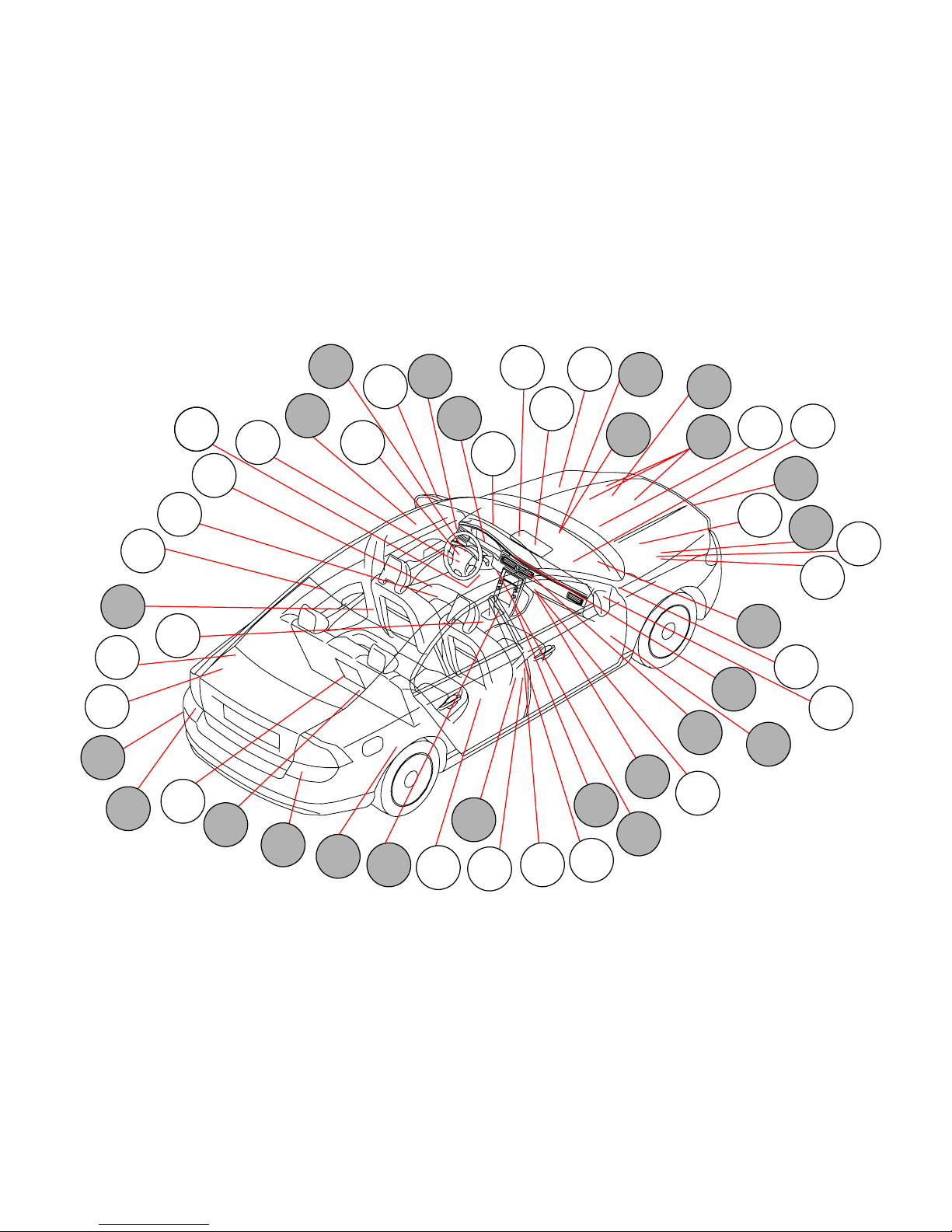
TP39127202 V70(08-), XC70(08-) & S80(07-) 2008 Supplement 36
AQS
17/13
SRM
DDM
PSM
HLDF
SCL
POT
ICM
PBM
SUM
KVM
RKE
SCU
MMM
LDM
RRX
CCM
SCM
ACM
CEM
PDM
HCM
PAM
DMM
RSM
ECM
IAM
CPM
SHM
BCM
SWM
SAS
DIM
FLR
BPM
TCM
WMM
FSM
RCM
GSM
BSC
SHM
OWS
AUD
SRS
PHM
RDM
TRM
DEM
LCM
LSM
Control modules
Overview of locations
Page 37

TP39127202 V70(08-), XC70(08-) & S80(07-) 2008 Supplement 37
Unit Designation Unit Designation
ACM 6/26 Alternator Control Module (ACM) PAM 4/86 Parking Assistance Module (PAM)
AQS 7/159 Air Quality Sensor (AQS) PBM 4/115 Parking Brake Module (PBM)
AUD 16/105 Audio Module (AUD) PDM 3/127 Passenger Door Module (PDM)
BCM 4/16 Brake Control Module (BCM) PHM 16/60 Phone Module (PHM)
BPM 16/147 Bluetooth Phone Module (BPM) POT 4/116 Power Operated Ta ilgate Module
(POT)
BSC 7/164 Body Sensor Cluster Stability Sensor
(BSC)
PSM 4/52 Power Seat Module (PSM)
CCM 4/6 Climate Control Module (CCM) RCM 27/4 Right Camera Module (RCM)
CEM 4/56 Central Electronic Module (CEM) RDM 3/129 Rear Right Door Module (RDM)
CPM 4/7 Combustion Preheater Module
(CPM)
RKE 4/119 Signal receiver, keyless vehicle
(RKE)
DDM 3/126 Driver Door Module (DDM) RRX 4/119.2 Remote Receiver Module (RRX)
DEM 4/82 Differential Electronic Module (DEM) RSM 7/149 Rain Sensor Module (RSM)
DIM 5/1 Driver Information Module (DIM) SAS 4/68 Steering Wheel Angle Sensor
Module (SAS)
DMM Damper Motor Module (DMM) SCL 4/102 Steering Column Lock Module (SCL)
ECM 4/46 Engine Control Module (ECM) SCM 16/35 Siren Control Module (SCM)
FLR 7/203 Forward-aimed radar (FLR) SCU 3/132 Start Control Module (SCU)
FSM 4/80 Forward Sensing Module (FSM) SHM 9/12 Seat Heating Module (SHM), driver’s
side
GSM 3/156 Gear Selector Module (GSM) SRM 4/33 Sunroof Module (SRM)
HCM 4/118 Headlamp Control Module (HCM) SRS 4/9 Supplemental Restraint System
Module (SRS)
HLDF 1 6/46 High Level Display Front module
(HLDF)
SUM 4/84 Suspension Mo dule (SUM)
IAM 16/1 Integrated Audio Module (IAM) SWM 3/130 Steering Wheel Module (SWM)
ICM 3/281 Infotainment Control Module (ICM) TCM 4/28 Transmission Control Module (TCM)
KVM 4/93 Keyless Vehicle Module (KVM) TMC 16/49 Traffic Message Channel module
(TMC)
LCM 27/3 Left Camera Module (LCM) TRM 4/110 Trailer Module (TRM)
LDM 3/128 Rear left Door Module (LDM) WMM 6/1 Wiper Motor Module (WMM)
LSM 3/111 Light Switch Module (LSM) 4/31 4/31 Fan control module
MMM 16/108 Multimedia Module (MMM) 4/71 4/71 Cooling fan control module
OWS 7/93 Occupant Weight Sensor (OWS) 17/13 17/13 Data link connector
Control modules
Overview designations
Page 38
TP39127202 V70(08-), XC70(08-) & S80(07-) 2008 Supplement 38
I6T
I6T
CAN
14
6
17/13
74/409
74/518
74/520
74/511
BU-BK
GN-BK
BU-BK
GN-BK
BU-BK
GN-BK
BU-BK
BU-BK
GN-BK
BU-BK
GN-BK
BU-BK
BU-BK
GN-BK
GN-BK
GN-BK
BU-BK
GN-BK
BU-BK
GN-BK
BU-BK
GN-BK
GN-BK
C1:4
C1:3
BU-BK
BU-BK
GN-BK
73/4007
73/4006
73/4005
73/4008
C3:48
C3:47
C1:6
C1:8
C1:9
C1:7
CEM
CAN
4/56
C1:8
C1:7
DEM
CAN
4/82
FSM
CAN
4/80
SWM
3/130
22 23
BU-BK
GN-BK
BU-WH
GN-OG
BU-WH
GN-OG
BU-BK
GN-BK
BU-BK
GN-BK
BU-BK
GN-BK
BU-BK
GN-BK
BU-BK
GN-BK
BU-BK
GN-BK
BU-BK
GN-BK
BU-BK
GN-BK
BU-BK
BU-BK
GN-BK
GN-BK
73/3021
73/3015
73/3014
73/3022
C1:6
C1:5
HCM
CAN
4/118
BU-BK
GN-BK
GN-BK
BU-BK
C1:12
C1:13
BCM
CAN
4/16
BU-BK
GN-BK
A:6
C1:19
C1:18
A:14
TCM
CAN
4/28
B:23
B:22
ECM
I5D
5 CYL
DIESEL
5 CYL
6 CYL
T
CAN
4/46
BU-BK
BU-BK
BU-BK
BU-BK
GN-BK
GN-BK
GN-BK
GN-BK
BU-BK
GN-BK
73/5016
73/5015
C1:16
12
C1:17
C1:16
C1:15
SUM
CAN
4/84
CAN
4/115
12
74/504
45 44
74/301
4
3
1 2
B:41
B:54
ECM
I5T
CAN
4/46
B:41
B:54
ECM
I6/I6T
MAN
AUTO
AUTO
MAN
AUTO
MAN
AUTO
CAN
4/46
B:45
B:58
73/4037
73/4038
2 1
PBM
BSC
CAN
7/164
YE-RD
GY-BU
YE-RD
GY-BU
4
3
FLR
CAN
7/203
8 CYL
ECM
V8
CAN
4/46
74/411
4 5
SAS
4/68
CAN
74/504
7 8
AUTO
74/504:44
74/504:45
6 CYL.T
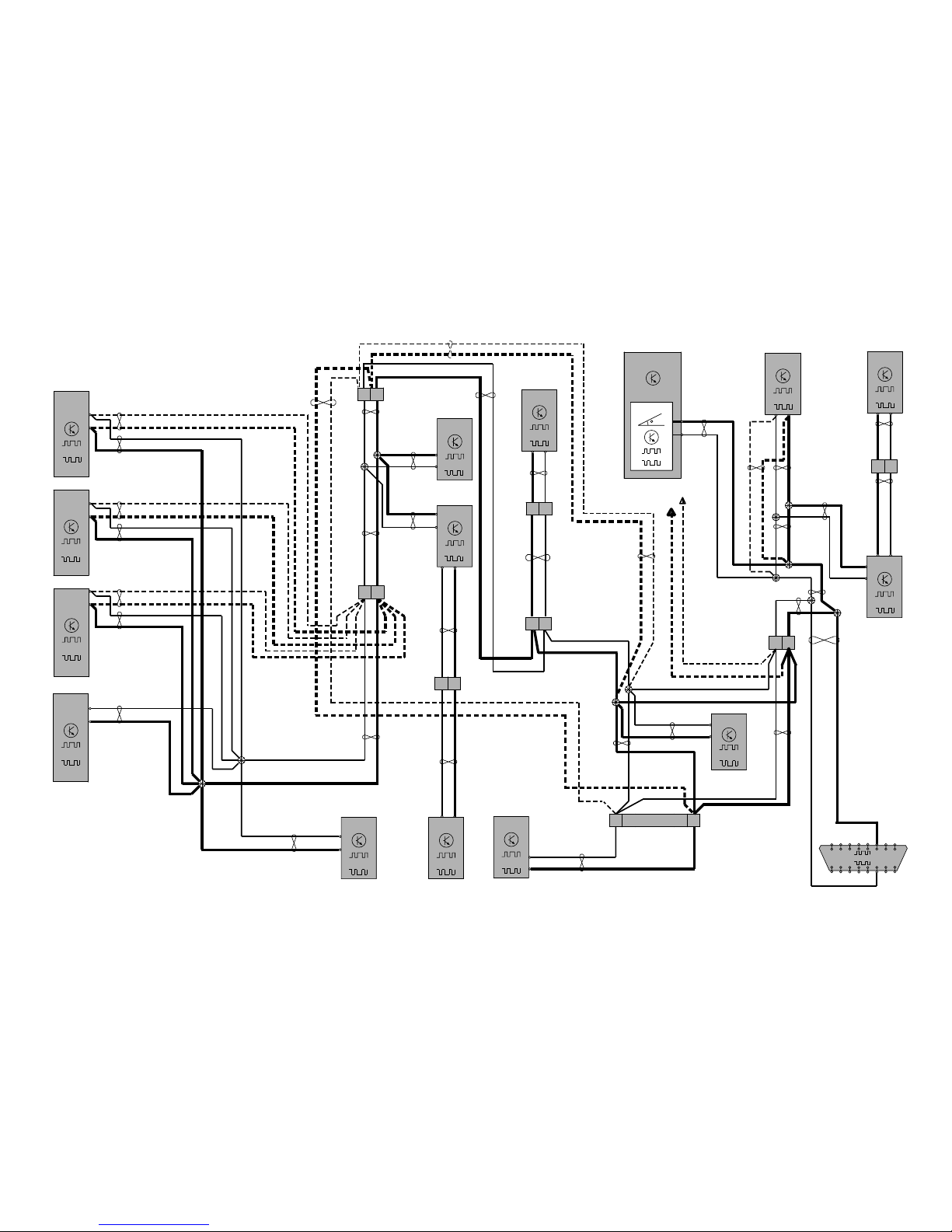
Control modules
Data communication high speed CAN
Page 39

TP39127202 V70(08-), XC70(08-) & S80(07-) 2008 Supplement 39
CAN
14
6
17/13
74/409
74/518
74/520
74/511
BU-BK
GN-BK
BU-BK
GN-BK
BU-BK
GN-BK
BU-BK
BU-BK
GN-BK
BU-BK
GN-BK
BU-BK
BU-BK
GN-BK
GN-BK
GN-BK
BU-BK
GN-BK
BU-BK
GN-BK
BU-BK
GN-BK
GN-BK
C1:4
C1:3
BU-BK
BU-BK
GN-BK
73/4007
73/4006
73/4005
73/4008
C3:48
C3:47
C1:6
C1:8
C1:9
C1:7
CEM
CAN
4/56
C1:8
C1:7
DEM
CAN
4/82
FSM
CAN
4/80
SWM
3/130
22 23
BU-BK
GN-BK
BU-WH
GN-OG
BU-WH
GN-OG
BU-BK
GN-BK
BU-BK
GN-BK
BU-BK
GN-BK
BU-BK
GN-BK
73/3021
73/3022
C1:6
C1:5
HCM
CAN
4/118
BU-BK
GN-BK
GN-BK
BU-BK
C1:12
C1:13
BCM
CAN
4/16
C1:19
C1:18
A:A3
A:A4
ECM
DW10
4 CYL
DIESEL
4 CYL
CAN
4/46
BU-BK
BU-BK
BU-BK
BU-BK
GN-BK
GN-BK
GN-BK
GN-BK
BU-BK
GN-BK
73/5016
73/5015
C1:16
12
C1:17
C1:16
C1:15
SUM
CAN
4/84
CAN
4/115
12
74/504
45 44
74/301
4
3
1 2
B:B4
B:A4
ECM
I4
MAN
MAN
CAN
4/46
73/4037
73/4038
2 1
PBM
BSC
CAN
7/164
YE-RD
GY-BU
YE-RD
GY-BU
4
3
FLR
CAN
7/203
74/411
4 5
SAS
4/68
CAN
74/504
7 8
74/504:44
74/504:45
Control modules
Data communication high speed CAN 4 Cyl.
Page 40

TP39127202 V70(08-), XC70(08-) & S80(07-) 2008 Supplement 40
3/156
GY-RD
1
7/149
LIN
C4:8
YE-BU
YE-BU
C1:36
YE-RD
1
6/1 LHD
WMM
CAN
4
6/1 RHD
LIN
C2:31
C1:35
CEM
4/56
2
LIN
2
7/199
IMS
SCM
16/35
2
74/411
A:7
BN-VT BN-VT BN-VT BN-VT
10
74/301
11
74/403
22
A:2
LIN
6
LIN
3/ 111
GSM
LIN
RSM
LIN
WMM
LIN
7/214
HBS
4/28
LIN
TCM
YE-RD
C4:7
VT
GN-VT
GN-OG
GN-BK
GN-OG
LIN
4/102
GY-BU
GY GY
4
C3:49
C2:17
GY-BN
GY-BN GY-BN
GY-BN
C2:40
LIN
BUS 1
LIN
BUS 2
LIN
BUS 3
LIN
BUS 2
BUS 0
C3:52
C3:51
LSM
C1:6
LIN
3/281
ICM
3/132
LIN
3
SCU
SCL
2
74/413
LIN
4/119.2
2
RRX
LIN
4/119
RKE
LIN
C3:50
C4:4
3
74/412
2
74/401
6
LIN
3/130
SWM
C1:7
C1:6
GY-BN
LIN
4/93
C4:14
KVM
Control modules
Data communication LIN 1:2
Page 41
TP39127202 V70(08-), XC70(08-) & S80(07-) 2008 Supplement 41
SHM
9/123/65
LIN
A:4
SHM
CCM
9/13
LIN
A:4
SHM
9/14
LIN
A:2
SHM
9/15
LIN
A:2
LIN
3
4/6
LIN
C1:12 C1:7
8/48
LIN
3
LIN
3/176
4
LIN
LCM
27/3
5
LIN
DDM
3/126
C2:4
LIN
PDM
3/127
C1:20
C2:4
BN-VTBN-VT
WH-GN
WH-GN
WH-GN
WH-GN
BN-VTBN-VTBN-VT
BN-VT
BN-VT
BN-VT
BN-VT
BN-VTBN-VT
LHD
WH-GN
RHD
WH-GNWH-GN
LHD
RHD
BU-BN
BU-BN
BU-BN
WH-GN
BU-BN
GN-WH
GN-WH
GN-WH
GN-WH
GN-WH
GN-WH GN-WH
1
74/501
1 2 4
74/401 74/414
15
74/409
4
74/507
ECM
LIN
4/46
8 CYL.
ECM
LIN
4/46
6 CYL.
ACM
G
LIN
6/26
A:25
C2:1
A:92
73/5021
73/5019
73/4010
16
74/409
ECM
LIN
4/46
5 CYL.T
ECM
LIN
4/46
5 CYL.D
A:46
A:88
LIN
LDM
3/128
20
LIN
RDM
3/129
20
LIN
RCM
27/4
5C1:20
BLIS
LHD
RHD
GN-WH
GN-WH
GN-WHGN-WH
LHD
RHD
GN-WH
BLIS
4
74/508
7
74/510
7
74/509
3 2
74/417
3/112
2
LIN
6/103
DMM
2
LIN
6/48
DMM
2
LIN
6/95
DMM
2
LIN
6/96
DMM
2
LIN
6/102
DMM
GN
GN
GN
S1
S3
YE
YE
YE
GN
LHD
LHD
RHD
RHD
BLIS
BLIS
GN-WH
GN-WH
ECM
LIN
4/46
4 CYL.
C:A2
ECM
LIN
4/46
4 CYL.D
B:K4
BU-BN
BU-BN
Control modules
Data communication LIN 2:2
Page 42
TP39127202 V70(08-), XC70(08-) & S80(07-) 2008 Supplement 42
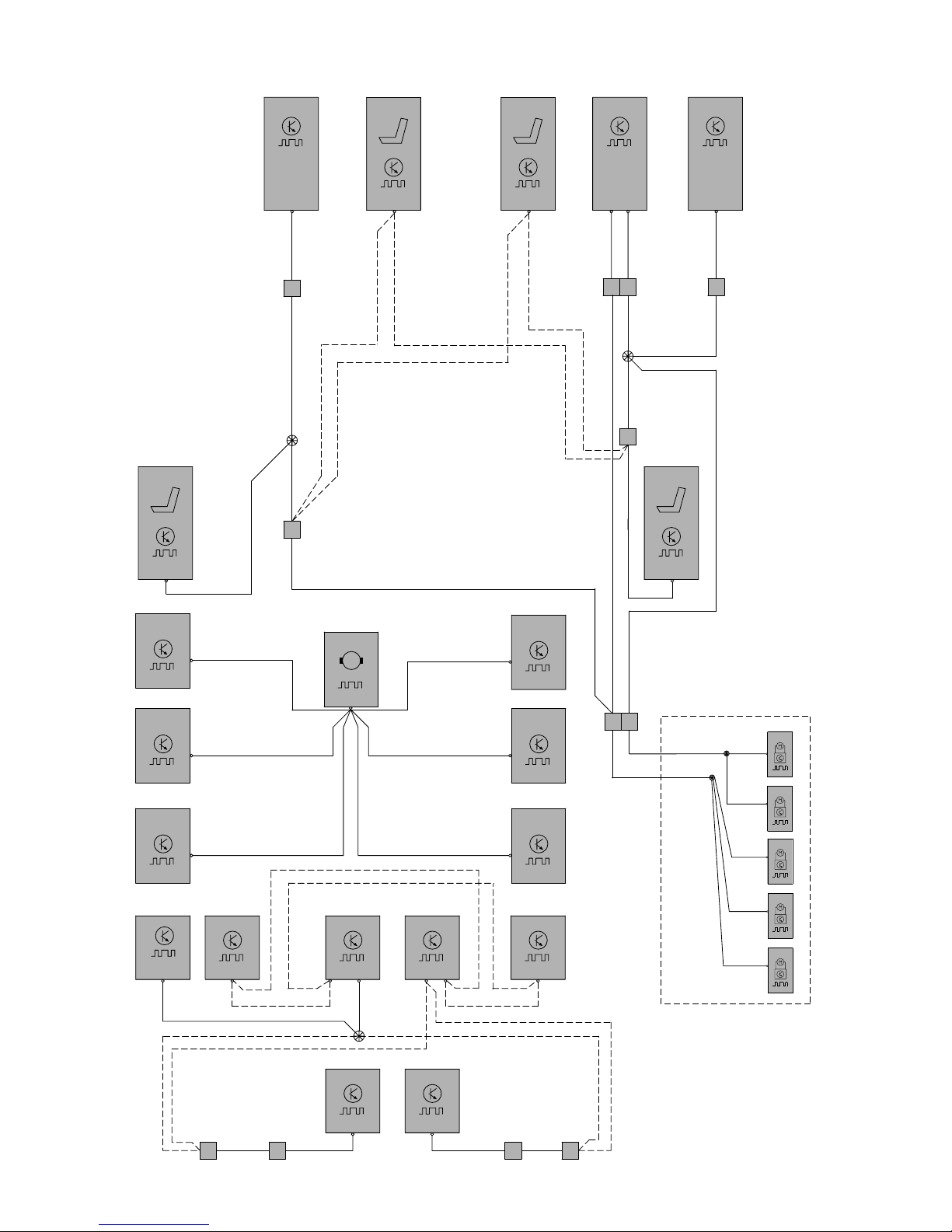
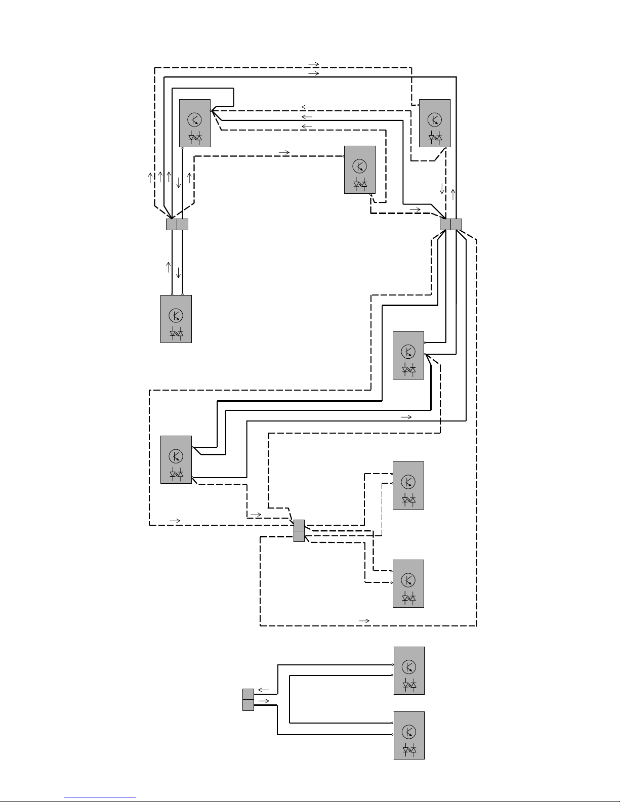
Control modules
Data communication MOST
O
O
O
OOO
O
O
O
16/1
IAM
16/105
AUD
74/402
OG
O
OG
OG
OG
OG
LHD
OG
OG
OG
OG
OG
OG
O
OG
O
OG
OG
OG
O
O
OG
C4:1
C4:2
C4:1
2
74/404
3/281
ICM
C2:1
C2:2
1
16/147
BPM
C2:1
C2:2
16/60
PHM
C4:1
C4:2
2 1
C4:2
16/108
MMM
C3:1
C3:2
16/145
RDAR
C3:2
C3:1
16/79
SUB
C2:1
C2:2
74/529
2
1
OG
OG
OG
OG
16/145
RDAR
C3:1
C3:2
16/79
SUB
C2:2
C2:1
74/529
1
2
OG
OG
O
O
OG
Page 43
TP39127202 V70(08-), XC70(08-) & S80(07-) 2008 Supplement 43
MAF
2(85)
3(30)
2/32
R10
GN-BN
BK-OGBK-OG
BK-YE
BK-YE
BK-YEBK-YE
YE-BK
YE-BK
YE-BK
YE-BK
YE-BK
GY
YE-BU
GN-BN
-BU
VT-BK
YE-GY
5(87)
1(86)
A:56
A:60
A:53
A:77
A:29
A:59
A:86
A:50
A:1
11B /30
15/31
2
1
2
1
GY-VT
VT-BK
YE
BN-GN
A:48
A:6
A:80
A:57
A:31
BU
YE-VT
BU-GY
7/16
7/25
7/17
4
1
3
2
A
2
1
30+
2
1
11B /37
11B /39
11B/38
11B/36
11B/40
11B/35
2
1
2
1
A:25
A:3
A:75
A:26
A:74
A:73
A:2
A:49
8/7
8/8
8/6
1
2
1
2
1
2
8/10
8/9
1
2
1
2
GN-BU
YE-BU
GY-YE
BU-OG
GY
VT-GY
GN-YE
YE-OG
BU-RD
BU
A:90
YE-RD
WH-OG
A:37
VT-GN
A:32
GY-VT
GN-BN
1
1
1
2
2
2
P
2
7/162
3
1
BU-RD
A:65
GY
A:19
BU-BN
A:64
3
7/165
8/120
6/143
4/109
1
2
3
1
2
6
5
4
3
1
2
4
A:82
GN-BN
4
A:15
BU
BU-GN
WH-BN
A:87
A:85
M
8/113
1
2
BU-BN
GY-BU
GY-BU
MAN
MAN
GY-BU
VT-RD
YE-BU
GN
73/3039
73/3051
A:92
A:66
A:71
A:28
BU
A:9
GN-BK
A:21
11 10 9 7 6
12 34 5
RD-VT
C
VT-BK
B
1
2
A:62
A:84
7/190
BN
VT-OG
A:8
A:58
7/191
YE-GY
GY-VT
P
BU-RD
VT-GN
YE-GN
GN-BK
BU-BK
7/15
GCU
I5D
CAN
ECM
4/46
DIESEL
I5D
2
1
11A/42
2
1
1
1 1
1 1
4
3
6
2
1
5
1
2
BU
BU
BU
BU
BU
BU
BU
9/38
74/301
74/504
74/512
74/512
73/3108
73/3094
20/22
20/23
20/24
20/25
20/26
73/3092
1
2
9/47
1
2
9/32
17
21
31/6831/XX10
8
7
GN-BN
D
GN-BN
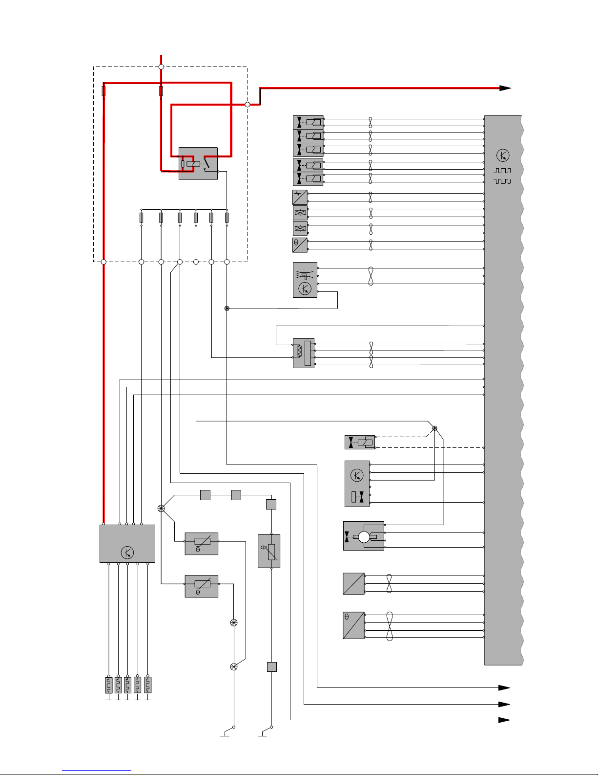
Group 23 Fuel system
Engine management system, 5 Cyl. Diesel 1:3
Page 44
TP39127202 V70(08-), XC70(08-) & S80(07-) 2008 Supplement 44
C2:12
3/284
1
2
BK-BU
BN-GN
RHD
17
ECM
B:6
B:4
B:2
CAN
3/9
1
2
4/93
C5:14
I5D
DIESEL
YE-OG
31/7
73/3031
73/5072 73/5071
73/3064
30+
CAN
CEM
F22
15/31
2/31
LIN
1
2
4/56
7/123
MAN
7/8
F4
1
2
F28
1
2
1
2
11A /1
1
2
R8
11B /17
1
2
31
25
11B /27
RD-BK
74/301
74/301
18
9
7
6
2
1
74/504
74/507
7/51
1
4
2
5
3
6
K8
C5:1C1:45
C2:76
3
2
C1:37
C1:44
C2:11
C2:29
C2:47
C2:55
B:48
B:38
VT-BN
VT-BN
VT-BN
AUTO
MAN
VT-BN
VT-BN
AUTO
VT-OG
VT-BN
VT-OG
13
14
15
3
1
2
C1:53
C1:65
C1:52
C1:51
B:27
B:16
BN
GY-BN
B:26
1
2
3
B:41
GN-BN
B:23
B:22
BN
GY-BN
GN-BN
WH-VT
GY-BK
GN-VT
BN-GN
GN
YE-OG
GN-OG
VT-GN
BU-RD
C2:66C2:54
RD-WH
VT-WH
VT-WH
74/514
KVM
3
17 18
B:25
B:31
BK-WH
WH
BK-WH
WH
12
B:47
BU-WH
BU-WH
BU-WH
B:5
B:3
B:1
BK-YE
BK-YE
BK-YE
GN-BN
BK-YE
YE-OG
WH
BK-WHBK-WH
BK-BU
BK-BU
BK-GN
BK-GN
BK-GN
WH
31/6631/XX5 31/84
LHD
LHD
LHD
RHD
RHD
3
B:42
4/46
A
GY-VT
C
B
BK-YE
1
2
11B/20
P
y
M
x
M
M
F
6/62
7/69
MEM
X
MEM
Y
6/33
M
5
46 12
24
BK-YE
GN-BN
D
VT-BK
AUTO
4/28
TCM
CAN
VT-BN
A:5
A:11
GY-BN
B:34
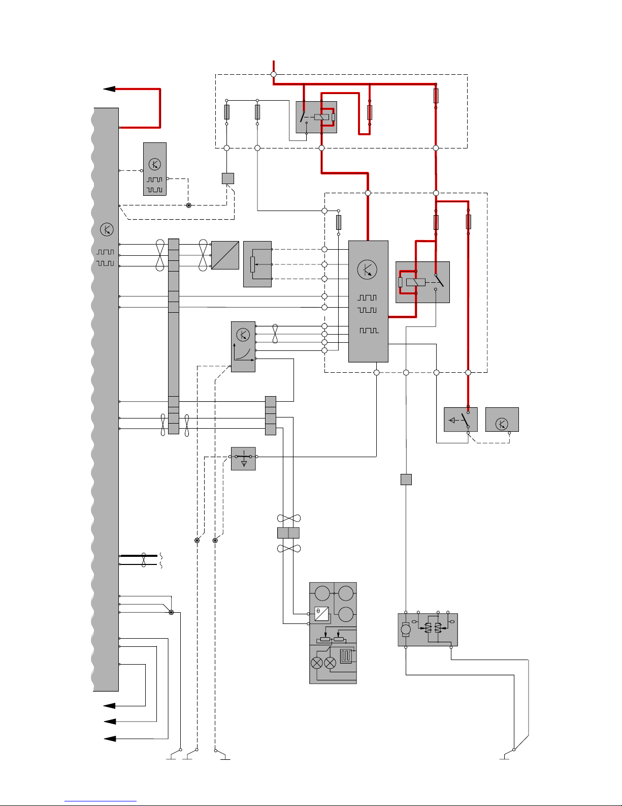
Group 23 Fuel system
Engine management system, 5 Cyl. Diesel 2:3
Page 45

TP39127202 V70(08-), XC70(08-) & S80(07-) 2008 Supplement 45
GY
GN-VT
8/98
1
2
A:23
A:93
CAN
A:44
A:63
A:41
A:78
A:61
ECM
GY-BU
WH-GN
BN-BU
GN
VT-WH
7/154
7/138
3
1
2
P
4/46
7/173
A:33
A:7
VT
GN-BN
VT-GY
A:10
QLT
2
7/166
3
1
GY-YE
A:36
GN-WH
A:42
BU-GN
A:34
1
2
8/111
M
1
2
1
2
3
DIESEL
I5D
6
3
2
4
1
ETA
6/120
6/118
BU-GN
YE-VT
YE-VT
A:24
A:72
A:67
A:18
BU-WH
BU-BK
A:47
GN-BU
A:94
A:11
VT-WH
5
4
3
2
1
BN-VT
GY-BU
YE-BK
A:4
A:5
A:81
A:40
VT-GN
A:52
WH-BU
Group 23 Fuel system
Engine management system, 5 Cyl. Diesel 3:3
Page 46

TP39127202 V70(08-), XC70(08-) & S80(07-) 2008 Supplement 46
M
M
6
5
4
1
2
3
2
1
R10
2
1
2/32
8/8
1
2
8/9
1
2
2(85)
1(86)
3(30)
5(87)
8/7
1
2
2
1
8/6
30+
GY-OG
BU
GN-BN
YE
GY-BN
7/16
3
1
2
2
1
ETA
C:E1
1
2
20/6
BU-OG1
2
20/5
20/4
2
1YE-BU
WH-VT
YE-GY
YE-GY
YE-GY
YE-GY
1
2
20/3
WH
6/120
73/3058
BK-YE
GN-VT
WH
WH
WH
WH
73/3039
4/46
7/25
YE-VT
GN-BN
YE-VT
BU-WH
A:D1
A:D2
A:E1
A:E2
B:A2
A:H1
A:H4
A:B2
A:B3
A:H2
A:H3
C:H3
C:H4
4 CYL
I4
ECM
C:G1
BN
C:F3
YE-VT
CAN
GN-VT
BU-GN
BU-BN
C
C:F1
C:E4
A:C3
A:A2
A:B1
YE-OG
VT-GY
GY-YE
GN-BU
15/31
1
2
11B/37
1
2
11B/38
11B/30
73/3053
BK-YE
2
1
8/114
7/165
4
BN-WH
GY-BN
A:D4
M
GY-BU
73/3084
GY-BU
YE-GY
GY-VT
A
1
2
11B/35
1
2
11B/36
1
2
11B/40
BU-BN
B
P
GY-BN
7/6
1
P
BU-BN
C:D2
GY-BU
2
1
8/45
C:D1
GY
BU-BN
C:B1
C:B2
YE-BU
C:C2
GN
WH-VT
C:C1
EGR
6
5
4
3
2
1
6/99
GY-BU
GY-BU
7/24
BK
SCRN
YE
A:E4
A:E3
1
2
73/3083
73/3094
31/XX10
BK-YE
B:L4
Group 23 Fuel system
Engine management system, 4 Cyl. 1:2
Page 47

TP39127202 V70(08-), XC70(08-) & S80(07-) 2008 Supplement 47
74/514
3
YE-OG
31/66
3
BK-YE
6/33
M
5
46 12
BK-YE
B:H3
17
ECM
B:M4
B:F4
B:B3
CAN
3/9
1
2
4/93
C5:14
4 CYL
I4
YE-OG
31/7
73/3012
73/5072
73/5071
30+
CAN
CEM
F22
15/31
2/31
LIN
1
2
4/56
7/123
MAN
7/8
3/284
1
2
F4
1
2
F28
1
2
1
2
11A /1
1
2
R8
3
52
1
11B/17
RD-BK
74/301
18
9
7
6
2
1
74/504
74/507
7/51
1
4
2
5
3
6
K8
C5:1C1:45
C2:76C2:12
3
2
C1:37
C1:44
C2:11
C2:29
C2:47
C2:55
B:E3
B:G2
B:G3
VT-BN
VT-OG
VT-BN
VT-OG
13
14
15
3
1
2
C1:53
C1:65
C1:52
C1:51
C:E1
C:C4
BN
GY-BN
1
2
3
B:F1
GN-BN
GYBN
BN
GY-BN
GN-BN
WH-VT
GY-BK
GN-VT
BN-GN
GN
YE-OG
GN-OG
VT-GN
BU-RD
C2:66C2:54
RD-WH
VT-WH
VT-WH
KVM
1718
B:H2
BK-WH
WH
BK-WH
WH
12
B:D2
BU-WH
BU-WH
BU-WH
B:M3
B:M2
BK-YE
BK-YE
BK-YE
BU-BN
BK-YE
WH
BK-WHBK-WH
BK-BU
BK-BU
BK-BU
BK-GN
BK-GN
BN-GN
BK-GN
WH
31/XX5
LHD
LHD
LHD
RHD
RHD
RHD
B:G1
4/46
GY-VT
A
C
1
2
11B/20
1
2
11B /27
P
y
M
x
M
M
F
6/62
7/69
MEM
X
MEM
Y
B:B4
B:A4
74/301
24
VT-BN
VT-BN
BU-BN
B
31/84
BK-YE
BK-YE
C:H1
A:G1
73/3084
3/270
BK-YE
BN-YE
2
1
Group 23 Fuel system
Engine management system, 4 Cyl. 2:2
Page 48

TP39127202 V70(08-), XC70(08-) & S80(07-) 2008 Supplement 48
M
M
6
5
4
1
2
3
2
1
R10
2
1
2/32
8/8
1
2
8/9
1
2
2(85)
1(86)
3(30)
5(87)
8/7
1
2
2
1
8/6
30+
GY-OG
BU
GN-BN
YE
GY-BN
7/16
3
1
2
2
1
ETA
C:E1
1
2
20/6
BU-OG1
2
20/5
20/4
2
1YE-BU
WH-VT
YE-GY
YE-GY
YE-GY
YE-GY
1
2
20/3
WH
6/120
73/3058
BK-YE
GN-VT
WH
WH
WH
WH
73/3039
4/46
7/25
YE-VT
GN-BN
YE-VT
BU-WH
A:D1
A:D2
A:E1
A:E2
B:A2
A:H1
A:H4
A:B2
A:B3
A:H2
A:H3
C:H3
C:H4
4 CYL
I4
ECM
C:G1
BN
C:F3
YE-VT
CAN
GN-VT
BU-GN
BU-BN
C
C:F1
C:E4
A:C3
A:A2
A:B1
YE-OG
VT-GY
GY-YE
GN-BU
15/31
1
2
11B/37
1
2
11B/38
11B/30
73/3053
BK-YE
2
1
8/114
7/165
4
BN-WH
GY-BN
A:D4
M
GY-BU
73/3084
GY-BU
YE-GY
GY-VT
A
1
2
11B/35
1
2
11B/36
1
2
11B/40
BU-BN
B
P
GY-BN
7/6
1
P
BU-BN
C:D2
GY-BU
2
1
8/45
C:D1
GY
BU-BN
C:B1
C:B2
YE-BU
C:C2
GN
WH-VT
C:C1
EGR
6
5
4
3
2
1
6/99
GY-BU
GY-BU
7/24
BK
SCRN
YE
A:E4
A:E3
1
2
73/3083
73/3094
31/XX10
BK-YE
B:L4
Group 23 Fuel system
Engine management system, 4 Cyl. Flexifuel 1:2
Page 49

TP39127202 V70(08-), XC70(08-) & S80(07-) 2008 Supplement 49
21
31/66
3
BK-YE
6/33
M
5
46 12
BK-YE
17
ECM
B:M4
B:F4
B:B3
CAN
3/9
1
2
4/93
C5:14
4 CYL
I4
BU-WH
31/7
73/3012
73/5072 73/5071
30+
CAN
CEM
15/31
2/31
LIN
4/56
7/123
MAN
7/8
3/284
1
2
F4
1
2
F28
1
2
1
2
11A /1
1
2
R8
3
52
1
11B/17
RD-BK
74/301
18
9
7
6
2
1
74/504
74/507
7/51
1
4
2
5
3
6
K10-A
C5:1C1:45
C2:56C2:12
C1:37
C1:44
C2:11
C2:29
C2:47
C2:55
B:E3
B:G2
B:G3
VT-BN
VT-BN
VT-OG
VT-BN
VT-OG
13
14
15
3
1
2
C1:53
C1:65
C1:52
C1:51
C:E1
C:C4
BN
GY-BN
1
2
3
B:F1
GN-BN
BN
GY-BN
GN-BN
WH-VT
GY-BK
GN-VT
BN-GN
GN
YE-OG
GN-OG
VT-GN
BU-RD
C2:66C2:54
RD-WH
VT-WH
VT-WH
KVM
1718
B:H2
BK-WH
WH
BK-WH
WH
12
B:D2
BU-WH
BU-WH
BU-WH
B:M3
B:M2
BK-YE
BK-YE
BK-YE
BU-BN
BK-YE
WH
BK-WHBK-WH
BK-BU
BK-BU
BK-BU
BK-GN
BK-GN
BN-GN
BK-GN
WH
31/XX5
LHD
LHD
LHD
RHD
RHD
RHD
B:G1
4/46
GY-VT
A
C
1
2
11B/20
1
2
11B /27
P
B:B4
B:A4
74/301
24
VT-BN
BU-BN
B
31/84
BK-YE
BK-YE
C:H1
A:G1
18 19
74/511B
74/511A
18 19
26/5
FlexiFuel
FlexiFuel
DC/AC
F17
1
2
73/5044
BU-WH
BU-WH
YE-VT
GN-BU
GN-BU
YE-VT
GN-BU
YE-VT
3
2
y
M
x
M
M
F
6/62
7/69
MEM
X
MEM
Y
GN-BU
YE-VT
C2:48
C2:30
B:H3
3/270
BK-YE
BN-YE
2
1
GYBN
73/3084
Group 23 Fuel system
Engine management system, 4 Cyl. Flexifuel 2:2
Page 50
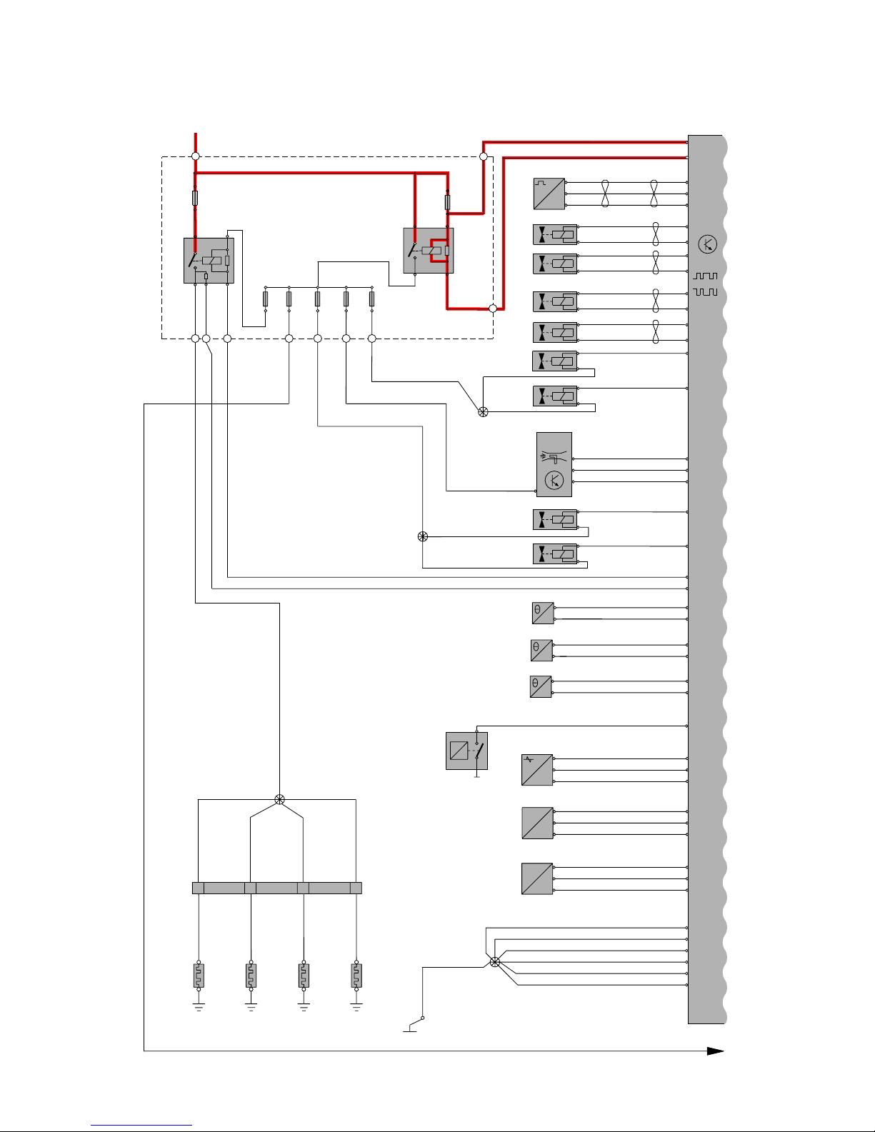
TP39127202 V70(08-), XC70(08-) & S80(07-) 2008 Supplement 50
MAF
YE-BU
VT-GY
7/77
1
2
WH
7/17
4
2
5
BU-GY
BU
YE-VT
A:B2
A:B3
A:C4
A
A:G4
A:H4
B:L4
B:M4
C:J2
C:K4
A:D3
C:H3
7/6
1
P
BU-BN
A:B1
15/31
3
31/XX5
A:G2
VT-OG
A:G1
P
2
7/71
3
1
GN-BU
B:F2
YE-GN
B:E2
BU-WH
B:C4
BN-GN
YE
7/16
1
2
A:A2
A:B4
7/25
B:C1
YE-VT
GY-VT
B:H4
GN-BN
1
2
3
C:H4
GN
WH-OG
A:D2
VT-WH
GN
7/154
1
2
B:H1
B:K3
BK-YE
BK-YE
BK-YE
BK-YE
BK-YE
BK-YE
2
1
BK-YE
VT
WH-OG
VT
GN
BU-BN
YE-GY
74/307
2
1
3 4
2
1
2
1
2
1
VT
VT
VT
VT
VT
VT
VT
VT
20/22
20/23
20/24 20/25
73/3012
GY-BU
GY-BU
8/133
2
1
VT-GN
8/77
2
1
GY-BU
2
1
5
3
2
1
5
3
1
30+
11B/30
2
1
11A/42
2
1
2
11B/36
1
2
11B/35
11B/38
2
11
2
11B/37
1
2
11B/33
73/3080
4/46
B:G4
RD-VT
B:E1
B:E3
B:E4
BU-BN
BU-BN
GY
7/162
2/14
R10
2/32
R11
1
2
3
2
1
8/6
GN-BU
C:L4
C:M4
2
1
8/7
GY-YE
C:L3
C:M3
2
1
8/8
VT-GY
C:L2
C:M2
YE-BU
BU-OG
GN-VT
2
1
8/9
YE-OG
C:M1
BU
2
1
8/82
YE-BU
YE-GY
YE-GY
B:M1
GY-VT
73/3050
73/3081
ECM
CAN
4 CYL.D
DW10
A:C1
2
1
8/132
B:M2
VT
7/174
B:A4
BN-BU
GN-OG
B:A1
WH-BU
B:A3
1
2
3
dP
C:L1
7
B:C2
Group 23 Fuel system
Engine management system, 4 Cyl. Diesel 1:2
Page 51

TP39127202 V70(08-), XC70(08-) & S80(07-) 2008 Supplement 51
C2:12
3/284
1
2
BK-BU
BN-GN
RHD
17
ECM
CAN
3/9
1
2
4/93
C5:14
DW10
4 CYL.D
31/7
73/5072
73/5071
30+
CAN
CEM
15/31
2/31
LIN
4/56
7/123
MAN
7/8
F4
1
2
F28
1
2
1
2
11A /1
1
2
R8
11B /17
1
2
31
25
11B /27
RD-BK
74/301
74/301
18
9
7
6
2
1
74/504
74/507
7/51
1
4
2
5
3
6
C5:1C1:45
3
2
C1:37
C1:44
C2:11
C2:29
C2:47
C2:55
C:G4
A:F4
VT-BN
VT-BN
VT-BN
VT-OG
VT-BN
VT-OG
13
14
15
3
1
2
C1:53
C1:65
C1:52
C1:51
C:B2
C:B1
BN
GY-BN
C:B3
1
2
3
A:C3
GN-BN
A:A3
A:A4
BN
GY-BN
GN-BN
WH-VT
GY-BK
GN-VT
BN-GN
GN
YE-OG
GN-OG
VT-GN
BU-RD
C2:66
C2:54
RD-WH
VT-WH
VT-WH
KVM
17 18
B:J4
B:H2
BK-WH
WH
BK-WH
WH
12
C:E3
BU-WH
BU-WH
BU-WH
WH
BK-WHBK-WH
BK-BU
BK-BU
BK-GN
BK-GN
BK-GN
WH
31/84
LHD
LHD
LHD
RHD
RHD
4/46
A
1
2
11B/20
P
y
M
x
M
M
F
6/62
7/69
MEM
X
MEM
Y
24
C:K2
C:K1
C:J1
73/3039
BU-BN
C:C4
C:A2
GN-BN
B:G1
B:J3
VT-OG
BN
B:G3
B:G2
GY-VT
YE-GY
BN-BU
C:C2
VT
7/190
1
2
7/191
1
2
2
7/21
3
1
4
3
1
6
5
8/120
BN-WH
WH-OG
B:D4
B:D2
B:D3
GY-OG
B:L1
YE-BU
WH-VT
B:L2
M
7/193
B:B4
B:B1
YE
VT-BN
GY
B:C3
2
7/54
3
1
GY
A:A1
YE-VT
A:D4
BU-WH
A:E3
2
3
1
BU-BN
BU-BN
BU-BN
+
-
3
C:F3
BN-WH
BN-WH
C1:8
Group 23 Fuel system
Engine management system, 4 Cyl. Diesel 2:2
Page 52

TP39127202 V70(08-), XC70(08-) & S80(07-) 2008 Supplement 52
Turbo
1
2
MAF
R10
2
1
2/32
8/9
1
2
8/10
1
2
2(85)
1(86)
3(30)
5(87)
8/8
1
2
2
1
8/7
30+
2
1
8/11
WH
7/17
1
5
2
YE-VT
BU-GY
BU
YE
BU
BK-OG
BK-R
D
BK-RD
YE-BU
BK-RD
BK-RD
BK-RD
31/90
31/89
4
2
2
3
2
1
20/6
43
2
1
20/4
VT-BN43
2
1
20/8
20/5
1
2
34 BU-OG
GY-BK
VT-BK
YE-GY
YE-GY
YE-GY
YE-GY
YE-GY
43
2
1
20/7
WH
WH
73/3058
73/3003
GN-VT
YE-BU
GY
BU-GN
BU-BN
WH
WH
WH
WH
WH
WH
73/3004
4/46
7/23
YE-RD
GN-RD
B
A
A:82
A:80
A:83
A:79
A:81
A:66
A:14
A:60
A:59
A:43
A:61
A:20
A:58
A:57
A:56
A:24
A:23
A:69
6 CYL
ECM
CAN
YE-GN
YE-GN
YE-GY
YE-GN
YE-GN
YE-GN
YE-GN
YE-GN
A:62
D
GY-BU
C
7/25
YE-VT
GN-BN
A:30
A:6
1
2
1
2
7/24
VT-OG
GY-BK
A:42
A:19
BU-RD
A:46
A:71
A:63
P
7/156
3
2
1
4
GY-BU
GYGY
GY
BU-BN
BU-OG
BU-BN
BU-BN
A:70
4
2
1
VT-BN
A:22
BU-RD
YE-OG
VT-GY
GY-YE
GN-BU
BU-BN
A:21
A:47
15/31
11
2
11B/37211B/36
1
2
11B/35
11B/30
73/3053
73/3010
73/3009
3
2
1
8/6
A:78
GN-WH
GY-VT
RD-VT
A:95
YE-OG
A:90
1
1
1
2
11B/38
1
2
7/166
3
A:73
6
5
4
3
2
1
ETA
6/120
BU-GN
BU-OG
A:75
A:45
A:74
A:17
YE
A:67
YE-VT
GN-VT
BU-RD
A:48
A:65
M
BK-OG
YE-GY
43
2
1
20/3
1
2
7/81
3
P
GY-BU
GY-BU
7/16
A:68
73/3039
QLT
1
2
20/16
+
BK-RD
GY-BU
8/28
8/68
7/165
1
3
2
A:37
GN-BN
4
A:13
BU-BN
GY-OG
GY
A:72
P
YE-GY
31/88
Group 23 Fuel system
Engine management system, 6 Cyl. Turbo 1:2
Page 53

TP39127202 V70(08-), XC70(08-) & S80(07-) 2008 Supplement 53
6 CYL
B:41
B:54
Turbo
1
25
3
ECM
B:6
B:4
B:2
CAN
3/9
1
2
4/93
C5:14
4/83
5
6
4
3
1
YE-OG
YE-OG
73/3012
73/5072 73/5071
30+
CAN
CEM
F22
15/31
2/31
LIN
1
2
4/56
7/8
F4
1
2
F28
1
2
1
2
1
1
2
R8
11B /17
2
11B/27
11A/1
RD-BK
18
17
74/301
18
9
29
7
6
2
1
74/504
74/507
7/51
1
4
2
5
3
6
K8
C5:1C1:45
C2:76C2:12
C1:3
C1:2
C1:37
C1:44
C2:11
C2:29
C2:47
C2:55
B:30
B:14
B:21
VT-BN
VT-OG
VT-BN
VT-OG
13
14
15
3
1
2
C1:65
B:53
B:31
BN
GY-BN
B:51
GN-BN
BN
GY-BN
GN-BN
GY-BK
GN-VT
YE-OG
GN-OG
VT-GN
BU-RD
C2:66C2:54
RD-WH
VT-WH
VT-WH
74/514
KVM
17 3
17 18
YE-OG
B:34
B:35
BK-WH
WH
BK-WH
WH
12
B:26
BU-WH
YE-OG
YE-OG
BU-WH
BU-WH
B:5
B:3
BK-YE
BK-YE
BK-YE
GY-BU
WH
BK-YE
YE-OG
WH
BK-WHBK-WH
YE-GY
WH-BN
BK-BU
BK-BU
BK-GN
BK-GN
WH
31/66
31/XX5 31/84
BK-YE
LHDLHD
RHDRHD
3
BK-YE
B:27
B:16
4/46
B
GY-VT
A
RD-VT
C
D
BK-YE
1
2
11B /20
P
y
M
x
M
M
F
6/62
7/69
MEM
X
MEM
Y
6/33
M
5
46 12
3/284
1
2
BK-BU
BK-GN
BN-GN
LHD
RHD
B:15
VT-BN
74/301
24
73/3064
VT-BN
VT-BR
74/511
31/7
PEM
4/28
TCM
CAN
VT-BN
A:5
A:11
GY-BN
B:13
Group 23 Fuel system
Engine management system, 6 Cyl. Turbo 2:2
Page 54

TP39127202 V70(08-), XC70(08-) & S80(07-) 2008 Supplement 54
6/73
M
2
1
GN-VT
A:67
BU-OG
A:11
A:74
A:75
A:56
A:59
A:58
A:6
A:30
A:61
A:60
A:48
BU-GN
YE-VT
GN-BN
YE-VT
7/25
6/120
2
20/3
1
2
43
YE-GY
YE-GY
YE-GY
YE-GY
YE-GY
YE-GY
YE-GY
YE-GY
YE-GN
VT-BK
VT-BN
YE-GN
YE-GN
GN-VT
34
2
1
20/4
20/5
1
2
43
20/6
1
2
43
20/7
1
2
43
20/8
1
2
43
31/88
BK
BK
BK
BK
BK-YE
BK
BK
BK
BK
ETA
73/3053
YE-GN
RD
VT-WH
BU-BN
VT-WH
GY-BK
VT-WH
BU-OG
YE-GN
YE-BU
A:57
A:54
A:55
A:62
YE-GN
A:64
VT-WH
GY-VT
RD-VT
WH-OG
WH
4/46
74/99
YE
B
A
C
A:95
A:79
A:78
A:81
A:80
A:83
A:82
A:85
A:84
A:66
A:70
A:68
A:12
A:15
A:69
ECM
8 CYL
V8
CAN
WH-BN
BU
BU-GN
WH-BN
BU
BU-GN
BK-YE
7/81
7/16
1
3
P
YE-VT
73/3006
73/3091
11B/35
11B /3 9
11B /3 7
11B/38
A:18
7/17
3
2
1
4
BU-GY
A:10
5
BU
2222
WH
WH
WH
WH
WH
WH
WH
WH
WH-GN
WH
GN-BU GN-BU
YE-OG
VT-GY
GN-WH
VT-OG
GY-BN
GY-YE
8/7
8/6
CYL2
CYL1
CYL4
CYL3
CYL6
CYL5
CYL8
CYL7
CYL1
CYL2
CYL3
CYL4
CYL5
CYL6
CYL7
CYL8
8/107
15/31
73/3074
74/99
2
1
2
1
2
1
2
1
2
1
2
1
2
1
2
1
2
1
8/8
8/9
8/10
8/11
BU-RD
YE-OG
VT-GY
GN-WH
VT-OG
GY-BN
GY-YE
BU-RD
8/115
8/116
5(87)
3(30)
1(86)
2(85)
2/32
1
2
11B/30
1111
11B /4 0211B /3 3
2
11
R10
30+
MAF
1
1
2
3
4
5
6
E
A:65
A:24
A:16
BU-RD
GY
YE
1
2
D
BU-BN
GY-BU
11B /3 6
2
1
20/12
1
2
43
20/13
1
2
43
31/90
31/89
31/100
31/XX10
7/156
1
3
4
2
1
2
A:71
A:46
A:47
A:14
BU-BN
BU-BN
GY-BU
GY GY
73/3058
73/3039
73/3094
73/3057
73/3056
M
YE-
B
U
RD
RD
P
VT-BN
WH
YE-BU
BK-YE
YE-GY
WH
GY-BU
4
5
6
7
12
1
2
3
2
74/133
73/3060
A:17
A:63
GY-YE
GY
BU-OG
GY-YE
GY
BU-OG
7/35
1
3
QLT
1
2
3
11
8
9
10
4
3
74/53
1
2
A:42
A:19
A:43
A:20
YE-RD YE-RD
GN-RD
GY-BK GY-BK
GN-RD
VT-OGVT-OG
7/24
7/23
1
2
1
2
7/6
P
2
1
3
5
2/239
R11
B
K
B
N
74/86
8
7
4
3
BU-BN
GY-BU
BU-BN
GY
Group 23 Fuel system
Engine management system, 8 Cyl. 1:2
Page 55
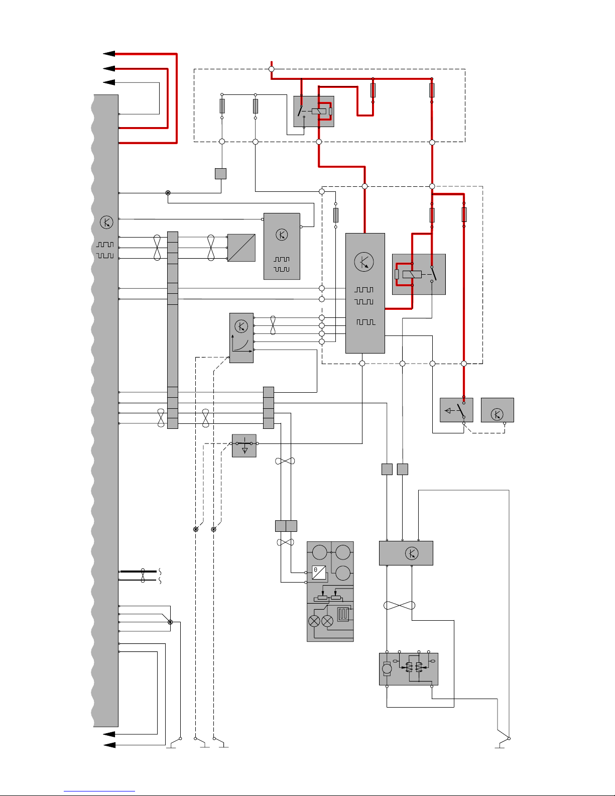
TP39127202 V70(08-), XC70(08-) & S80(07-) 2008 Supplement 55
17
ECM
B:3
B:2
B:1
CAN
3/9
1
2
4/93
C5:14
8 CYL
V8
4/83
5
6
4
3
1
YE-OG
YE-OG
31/7
73/3031
73/5072 73/5071
30+
CAN
CEM
F22
15/31
2/31
LIN
1
2
4/56
7/8
F4
1
1
2
F28
1
2
1
2
11A /1
1
2
R8
11B /17
1
1
2
25
3
11B /27
RD-BK
18
74/301
18
9
29
7
6
2
1
74/504
74/507
7/51
1
4
2
5
3
6
K8
C5:1C1:45
C2:76
3
2
C1:37
C1:44
C2:11
C2:29
C2:47
C2:55
B:41
B:54
B:27
B:20
VT-BN
RD-VT
GY-VT
WH-OG
VT-OG
VT-BN
VT-OG
13
14
15
3
1
2
C1:65
B:8
B:19
BN
GY-BN
B:12
GN-BN
BN
GY-BN
GN-BN
GN-VT
GY-BK
YE-OG
GN-OG
VT-GN
BU-RD
C2:66C2:54
RD-WH
VT-WH
VT-WH
74/514
KVM
17 3
17 18
YE-OG
B:9
B:29
BK-WH
WH
BK-WH
WH
12
B:28
BU-WH
YE-OG
YE-OG
BU-WH
BU-WH
B:4
B:6
BK-YE
BK-YE
BK-YE
B:5
BK-YE
GY-BU
BU-BN
BK-YE
YE-OG
WH
BK-WH
BK-WH
WH-BN
YE-GY
BK-BU
BK-BU
BK-BU
BK-GN
WH
31/6631/XX5
BK-YE
LHD
LHD
LHD
RHD
RHD
RHD
3
BK-YE
B:46
B:16
4/46
C
B
A
E
D
BK-YE
P
y
M
x
M
M
F
6/62
7/69
MEM
X
MEM
Y
6/33
M
5
46 12
C2:12
3/284
2
BK-GN
BK-GN
BN-GN
B:45
B:58
1
2
11B/20
B:30
VT-BN
74/301
24
73/3064
VT-BN
VT-BR
31/84
74/511
PEM
4/28
TCM
CAN
VT-BN
A:5
A:11
GY-BN
B:15
Group 23 Fuel system
Engine management system, 8 Cyl. 2:2
Page 56

TP39127202 V70(08-), XC70(08-) & S80(07-) 2008 Supplement 56
1
4
3
2
2
4
3
1
B:E2
B:M1
B:C1
B:H1
GY-BN
YE-BU
WH-OG
YE-GN
YE-GN
VT-GN
GN-BN
7/15
C:C1
1
2
O
O
2
CAN
2
8/18
73/3039
GY-BU
ECM
11B/38
2
1
1
2
11B/39
4/46
B:G1
GY-VT
C:B2
C:C2
WH-VT
YE-BU
GN
BU-BN
GY-BU
GY-BU
B:D1
YE-VT
A:B2
GN-BN
A:B3
7/25
2
1
73/3079
YE-BU
7/82
B:E1
C:B1
YE-BU
GY-BU
GY-VT
6/99
M
12
5
3
4
6
4CYL
Petrol
73/3006
YE-GN
YE-GN
R10
2
1
2/32
5
3
30+
15/31
11B/30
2
1
Group 23 Fuel system
Emission control, 4 Cyl.
Page 57

TP39127202 V70(08-), XC70(08-) & S80(07-) 2008 Supplement 57
GN-BN
2
3
4
1
2
1
4
3
1
4
3
2
3
4
1
2
A:45
A:89
A:22
A:40
A:88
A:27
A:26
A:77
A:29
A:28
A:76
A:92
A:86
GY-BK
YE-BU
VT
8 CYL
V8
VT-GN
GN
YE-BU
GN-BN
GY-VT
YE-BU
BU-BK
WH-GN
VT-BN
GN-BK
YE-BU
BU-WH
YE-BK
YE-BU
YE
YE-GN
73/3006
7/104
7/103
7/15
7/82
B:33
31
2
1
2
8/18
O
2
2
O
2
O
O
2
CAN
1
6/67
1
3
8/19
73/3039
GY-BU GY-BU
YE-BU
GY-BU
BU
ECM
74/301
17
4/46
B:16
GY-VT
B:4
GY-BU
1
8/81
2
YE-GY
A:90
B:48
33
M
2
4
B:45
B:58
2
74/512
4
VT-OG
BU-GY
VT-OG
BU-GY
GN-OG
BU
BU-GYBU-GY
VT-OGVT-OG
A:87
GY-BU
YE-BK
2
1
8/117
A:91
GY-BU
BN-VT
2
1
8/118
BU
GN-OG
BU
GN-OG
GN-OG
A:41
73/3061
A:32
A:34
A:72
A:31
A:33
A:7
73/3059
7/173
7/172
2
3
1
1
2
3
7/189
2
3
1
VT
GN-VT
GN-BN
VT
YE-BU
GN-BN
VTVT
YE-RD
GN-BN
VT
WH-GN
GN-BN
GN-BN
7/188
2
3
1
32
39
74/504
21
37
38
B:23
11B /38
2
11
2
11B /39
30+
2/32 R10
11B /30
2
1
1(86)
2(85)
3(30)
5(87)
11B /41
2
1
15/31
7
74/512
3
1
2
5
YE-RD
VT
GN-BN
74/86
Group 23 Fuel system
Emission control, 8 Cyl.
Page 58

TP39127202 V70(08-), XC70(08-) & S80(07-) 2008 Supplement 58
1
30+
2
31/2
11A/43
RD-WH
15/31
1
2
11A/44
74/301
4/46
ECM
CAN
C:E1
B:F1
C:C4
4 CYL
I4
A:C3
1
2
7/16
P
1
2
4
3
7/8
4/71
GN-BN
GY-BN
BN
GN-BN
GY-BN
B:C2
VT
BK-BU
BK-BU
BN
YE
14
13
15
2
1
B:A4
B:B4
GY-BN
73/3084
GY-BN
Group 26 Cooling system
Cooling fan, 4 Cyl.
Page 59
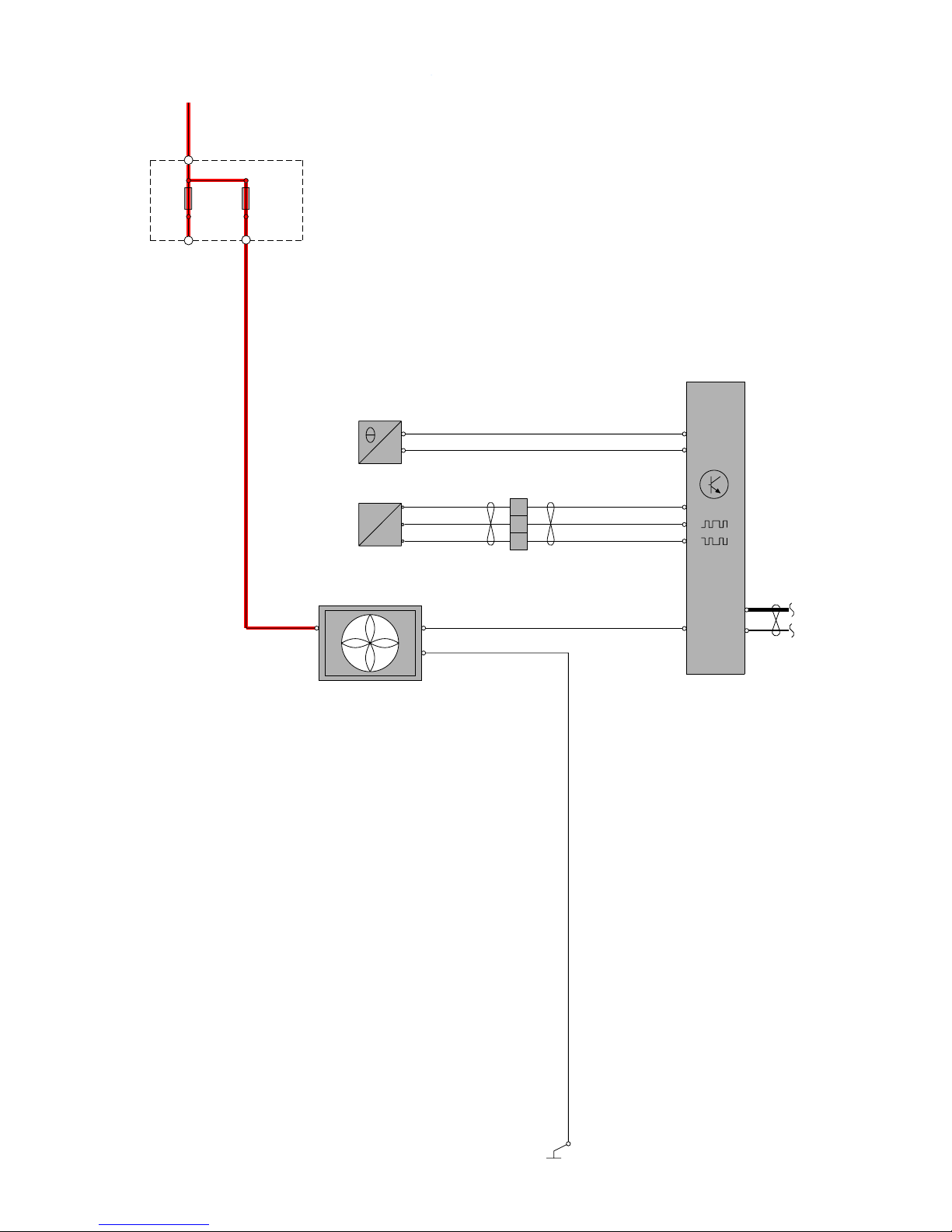
TP39127202 V70(08-), XC70(08-) & S80(07-) 2008 Supplement 59
y
1
30+
2
31/2
11A/43
RD-WH
15/31
1
2
11A/44
74/301
4/46
ECM
CAN
C:B2
C:B3
C:B1
4 CYL.
DIESEL
DW10
A:A2
1
2
7/16
P
1
2
4
3
7/8
4/71
GN-BN
GY-BN
BN
GN-BN
GY-BN
A:C2
VT
BK-BU
BK-BU
BN
YE
14
13
15
2
1
A:A4
A:A3
BN-GN
A:B4
Group 26 Cooling system
Cooling fan, 4 Cyl. Diesel
Page 60

TP39127202 V70(08-), XC70(08-) & S80(07-) 2008 Supplement 60
1
30+
2
31/2
11A/43
RD-WH
15/31
1
2
11A/44
74/301
4/46
ECM
A:60
CAN
A:56
B:27
B:26
B:16
DIESEL
I5D
1
2
7/16
P
1
2
4
3
7/8
4/71B
GN-BN
GY-BN
BN
GN-BN
GY-BN
B:58
VT
BK-BU
BK-BU
BN
YE
BN-GN
14
13
15
2
1
B:23
B:22
Group 26 Cooling system
Cooling fan, 5 Cyl. Diesel
Page 61

TP39127202 V70(08-), XC70(08-) & S80(07-) 2008 Supplement 61
1
30+
2
31/2
11A/43
5 CYL T
RD-WH
15/31
1
2
11A/44
73/3089
74/301
4/46
ECM
A:68
CAN
A:13
B:53
B:51
B:31
5 CYL T
6 CYL
5 CYL .T
6 CYL
I5 T
I6/I6T
1
2
7/16
A:42
A:12
1
2
7/16
P
1
2
4
3
7/8
4/71
GN-BN
GY-BN
BN
GN-BN
GY-BN
B:8
VT
BK-BU
BK-BU
BN
BU
YE
YE
BN-GN
14
13
15
2
1
B:54
B:41
BK-BU
6 CYL
/ 4/71B
Group 26 Cooling system
Cooling fan, 5 Cyl. Turbo & 6 Cyl.
Page 62
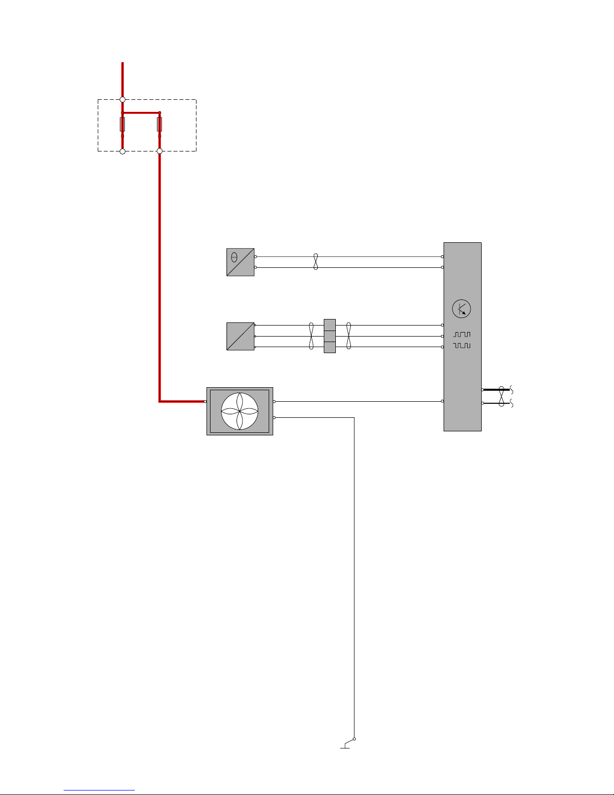
TP39127202 V70(08-), XC70(08-) & S80(07-) 2008 Supplement 62
1
30+
2
31/2
11A/43
RD-WH
15/31
1
2
11A/44
74/301
4/46
ECM
A:68
CAN
A:12
B:8
B:12
B:19
8 CYL
V8
1
2
7/16
P
1
2
4
3
7/8
4/71B
GN-BN
GY-BN
BN
GN-BN
GY-BN
B:49
VT
BK-BU
BN
YE
YE
14
13
15
2
1
B:45
B:58
Group 26 Cooling system
Cooling fan, 8 Cyl.
Page 63

TP39127202 V70(08-), XC70(08-) & S80(07-) 2008 Supplement 63
Group 27 Engine controls
Cruise control 4 Cyl.
WH
BN BN
C1:33
C1:34
WH
BN
WH
C1:46
C1:45
7/31
4/16
N
C1:12
C1:13
YE-VT
VT-RD
C1:26
C1:38
BCM
CAN
N
7/32
7/124
1
3
2
C1:27
GN-BK
2
1
2
1
73/3103
73/3102
73/3101
73/3100
BN
WH
2
30+
1
2
11A/2
RD-BU
15/31
3/130
1
2
C3:70
GN-WH
GN-BK
C3:51
C1:8
C1:7
C3:1
F7
73/4016
73/4017
C1:45 C5:2
4/56
CEM
CAN
LIN
LIN
C1:50
C1:49
C1:2
SWM
CAN
C3:3
C3:4
18/4
3
1
SWSL
3/4
LIN
BK
BK
LHD
BK
RHD
BK
31/83
B:A4
B:B4
31/84
74/301
4/46
ECM
B:D2
BU-WH
73/5072
BK-BU
BK-GN
BK-BU
BK-GN
CAN
YE-VT
C:F1
2
M
6
3
C:E4
YE-VT
BU-GN
C:F3
ETA
6/120
4
1
C:H4
GN-VT
BU-WH
C:G1
73/5071
31/7
LHD
RHD
LHD
RHD
74/504
4 CYL.
Petrol
7/51
1
4
2
5
3
6
C2:11
C2:29
C2:47
C2:55
YE-OG
GN-OG
VT-GN
BU-RD
BU-WH
CAN
C1:6
C1:2
5/1
DIM
4/80
FSM
CAN
C1:6
C1:7
2/31
F4
1
2
1
2
R8
11B/17
1
2
31
25
11B/27
C1:65
BU-WH
GN-VT
17
12
I4
5
BN
C:H3
3/284
1
2
BK-BU
RHD
BK-GN
LHD
3/9
1
2
C2:12
11A/1
1
2
F28
1
2
C2:66C2:54
RD-WH
VT-WH
7/203
YE-RD
GY-BU
74/411
YE-RD
GY-BU
C1:8
C1:9
FLR
CAN
43
GY-BK
4 5
C3:48
C3:47
ACC
RD-BK
C5:1
BN-GN
3/39
2
3
GN-VT
C2:33
BK-GN
LHD
S80
Page 64

TP39127202 V70(08-), XC70(08-) & S80(07-) 2008 Supplement 64
Group 27 Engine controls
Cruise control 4 Cyl. Diesel
WH
BN BN
C1:33
C1:34
WH
BN
WH
C1:46
C1:45
7/31
4/16
N
C1:12
C1:13
YE-VT
VT-RD
C1:26
C1:38
BCM
CAN
N
7/32
7/124
1
3
2
C1:27
GN-BK
2
1
2
1
73/3103
73/3102
73/3101
73/3100
BN
WH
2
30+
1
2
11A/2
RD-BU
15/31
3/130
1
2
C3:70
GN-WH
GN-BK
C3:51
C1:8
C1:7
C3:1
F7
73/4016
73/4017
C1:45 C5:2
4/56
CEM
CAN
LIN
LIN
C1:50
C1:49
C1:2
SWM
CAN
C3:3
C3:4
18/4
3
1
SWSL
3/4
LIN
BK
BK
LHD
BK
RHD
BK
31/83
A:A4
A:A3
31/84
74/301
4/46
ECM
C:E3
BU-WH
73/5072
BK-BU
BK-GN
BK-BU
BK-GN
CAN
73/5071
31/7
LHD
RHD
LHD
RHD
74/504
4CYL.
7/123
MAN
C1:53
C1:52
C1:51
1
2
3
WH-VT
BN-GN
GN
7/51
1
4
2
5
3
6
C2:11
C2:29
C2:47
C2:55
YE-OG
GN-OG
VT-GN
BU-RD
BU-WH
CAN
C1:6
C1:2
5/1
DIM
4/80
FSM
CAN
C1:6
C1:7
2/31
F4
1
2
1
2
R8
11B/17
1
2
31
25
11B/27
C1:65
BU-WH
GN-VT
17
12
DIESEL
DW10
3/284
1
2
BK-BU
RHD
BK-GN
LHD
3/9
1
2
C2:12
11A/1
1
2
F28
1
2
C2:66C2:54
RD-WH
VT-WH
7/203
YE-RD
GY-BU
74/411
YE-RD
GY-BU
C1:8
C1:9
FLR
CAN
43
GY-BK
4 5
C3:48
C3:47
ACC
RD-BK
C5:1
BN-GN
VT-OG
A:G1
GY-BU
8/77
2
1
GY-BU
73/3080
1
2
11B/38
2/32:5
15/31
3/39
2
3
C2:33
GN-VT
LHD
BK-GN
S80
Page 65

TP39127202 V70(08-), XC70(08-) & S80(07-) 2008 Supplement 65
Group 27 Engine controls
Cruise control 5 Cyl. & 6 Cyl.
WH
BN BN
C1:33
C1:34
WH
BN
WH
C1:46
C1:45
7/31
4/16
N
C1:12
C1:13
YE-VT
VT-RD
C1:26
C1:38
BCM
CAN
N
7/32
7/124
1
3
2
C1:27
GN-BK
2
1
2
1
73/3103
73/3102
73/3101
73/3100
BN
WH
2
30+
1
2
11A/2
RD-BU
15/31
3/130
1
2
C3:70
GN-WH
GN-BK
C3:51
C1:8
C1:7
C3:1
F7
73/4016
73/4017
C1:45 C5:2
4/56
CEM
CAN
LIN
LIN
C1:50
C1:49
C1:2
SWM
CAN
C3:3
C3:4
18/4
3
1
SWSL
3/4
LIN
BK
BK
LHD
BK
RHD
BK
31/83
31/84
BU-WH
73/5072
BK-BU
BK-GN
BK-BU
BK-GN
73/5071
31/7
LHD
RHD
LHD
RHD
74/504
7/123
MAN
C1:53
C1:52
C1:51
1
2
3
WH-VT
BN-GN
GN
7/51
1
4
2
5
3
6
C2:11
C2:29
C2:47
C2:55
YE-OG
GN-OG
VT-GN
BU-RD
BU-WH
CAN
C1:6
C1:2
5/1
DIM
4/80
FSM
CAN
C1:6
C1:7
2/31
F4
1
2
1
2
R8
11B/17
1
2
31
25
11B/27
C1:65
GN-VT
17
A:14
A:6
TCM
4/28
CAN
LIN
AUTO
3/284
1
2
BK-BU
RHD
BK-GN
LHD
3/9
1
2
C2:12
11A/1
1
2
F28
1
2
C2:66C2:54
RD-WH
VT-WH
YE-RD
GY-BU
74/411
YE-RD
GY-BU
C1:8
C1:9
FLR
CAN
43
GY-BK
4 5
3/156
A:7
74/411
BN-VT
BN-VT BN-VT BN-VT
10
74/301
11
74/403
22
A:2
LIN
GSM
C3:48
C3:47
ACC
RD-BK
C5:1
BN-GN
B:54
B:41
74/301
4/46
ECM
B:26
CAN
YE
A:19
3
M
6
5
A:88
BU-RD
GN-VT
A:65
PETROL
ETA
6/120
2
1
A:75
BU-OG
BU-GN
A:14
I5T&I6
BU-WH
12
GN-VT
A:67
2
M
6
3
A:48
BU-RD
YE
A:65
ETA
6/120
4
1
A:74
BU-OG
BU-GN
A:17
4
YE-VT
A:74
5
YE-VT
A:75
5CYL T
6CYL
6CYL
5CYL T
5CYL T
5CYL T
5CYL T
5CYL T
5CYL T
6CYL
6CYL
6CYL
6CYL
6CYL
7/203
5CYL.T
6CYL.
B:13
GY-BU
A:5
Page 66
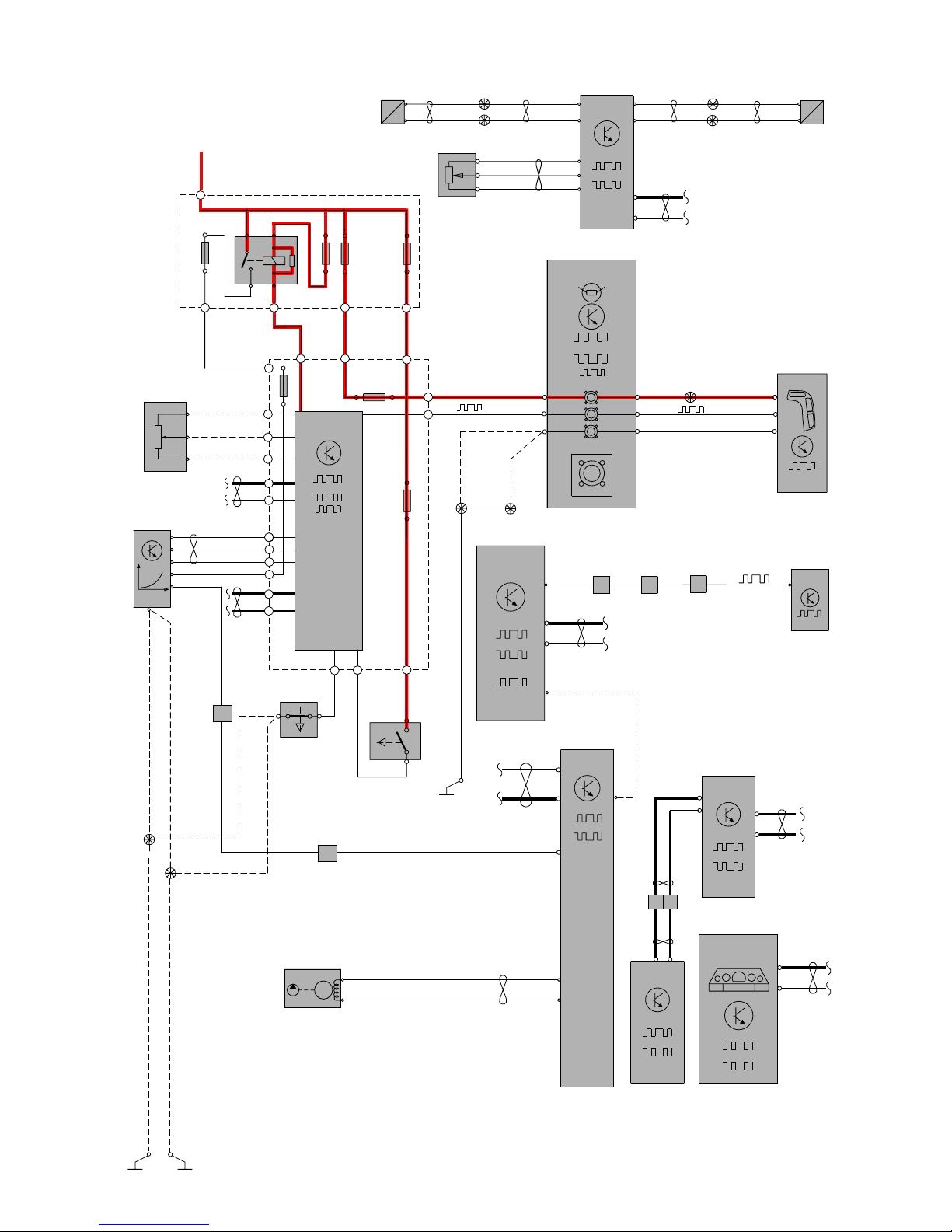
TP39127202 V70(08-), XC70(08-) & S80(07-) 2008 Supplement 66
Group 27 Engine controls
Cruise control 5 Cyl. Diesel
WH
BN BN
C1:33
C1:34
WH
BN
WH
C1:46
C1:45
7/31
4/16
N
C1:12
C1:13
YE-VT
VT-RD
C1:26
C1:38
BCM
CAN
N
7/32
7/124
1
3
2
C1:27
GN-BK
2
1
2
1
73/3103
73/3102
73/3101
73/3100
BN
WH
2
30+
1
2
11A/2
RD-BU
15/31
3/130
1
2
C3:70
GN-WH
GN-BK
C3:51
C1:8
C1:7
C3:1
F7
73/4016
73/4017
C1:45 C5:2
4/56
CEM
CAN
LIN
LIN
C1:50
C1:49
C1:2
SWM
CAN
C3:3
C3:4
18/4
3
1
SWSL
3/4
LIN
BK
BK
LHD
BK
RHD
BK
31/83
B:22
B:23
31/84
74/301
4/46
ECM
B:47
BU-WH
73/5072
BK-BU
BK-GN
BK-BU
BK-GN
CAN
73/5071
31/7
LHD
RHD
LHD
RHD
74/504
5CYL.
7/123
MAN
C1:53
C1:52
C1:51
1
2
3
WH-VT
BN-GN
GN
7/51
1
4
2
5
3
6
C2:11
C2:29
C2:47
C2:55
YE-OG
GN-OG
VT-GN
BU-RD
BU-WH
CAN
C1:6
C1:2
5/1
DIM
4/80
FSM
CAN
C1:6
C1:7
2/31
F4
1
2
1
2
R8
11B/17
1
2
31
25
11B/27
C1:65
BU-WH
GN-VT
17
12
DIESEL
A:14
A:6
TCM
4/28
CAN
LIN
AUTO
3/284
1
2
BK-BU
RHD
BK-GN
LHD
3/9
1
2
C2:12
11A/1
1
2
F28
1
2
C2:66C2:54
RD-WH
VT-WH
7/203
YE-RD
GY-BU
74/411
YE-RD
GY-BU
C1:8
C1:9
FLR
CAN
43
GY-BK
4 5
3/156
A:7
74/411
BN-VT
BN-VT BN-VT BN-VT
10
74/301
11
74/403
22
A:2
LIN
GSM
C3:48
C3:47
ACC
RD-BK
C5:1
BN-GN
1
2
8/ 111
M
BU-BK
A:47
GN-BU
A:94
B:34
GY-BU
A:5
Page 67

TP39127202 V70(08-), XC70(08-) & S80(07-) 2008 Supplement 67
Group 27 Engine controls
Cruise control 8 Cyl.
WH
BN BN
C1:33
C1:34
WH
BN
WH
C1:46
C1:45
7/31
4/16
N
C1:12
C1:13
YE-VT
VT-RD
C1:26
C1:38
BCM
CAN
N
7/32
7/124
1
3
2
C1:27
GN-BK
2
1
2
1
73/3103
73/3102
73/3101
73/3100
BN
WH
2
30+
1
2
11A/2
RD-BU
15/31
3/130
1
2
C3:70
GN-WH
GN-BK
C3:51
C1:8
C1:7
C3:1
F7
73/4016
73/4017
C1:45 C5:2
4/56
CEM
CAN
LIN
LIN
C1:50
C1:49
C1:2
SWM
CAN
C3:3
C3:4
18/4
3
1
SWSL
3/4
LIN
BK
BK
LHD
BK
RHD
BK
31/83
B:58
B:45
31/84
74/301
4/46
ECM
B:28
BU-WH
73/5072
BK-BU
BK-GN
BK-BU
BK-GN
CAN
GN-VT
A:67
2
M
6
3
A:24
BU-RD
YE
A:65
ETA
6/120
4
1
A:74
YE-VT
BU-GN
A:11
73/5071
31/7
LHD
RHD
LHD
RHD
74/504
8 CYL.
7/51
1
4
2
5
3
6
C2:11
C2:29
C2:47
C2:55
YE-OG
GN-OG
VT-GN
BU-RD
BU-WH
CAN
C1:6
C1:2
5/1
DIM
4/80
FSM
CAN
C1:6
C1:7
2/31
F4
1
2
1
2
R8
11B/17
1
2
31
25
11B/27
C1:65
BU-WH
GN-VT
17
12
V8
5
BU-OG
A:75
A:14
A:6
TCM
4/28
CAN
LIN
AUTO
3/284
1
2
BK-BU
RHD
BK-GN
LHD
3/9
1
2
C2:12
11A/1
1
2
F28
1
2
C2:66C2:54
RD-WH
VT-WH
7/203
YE-RD
GY-BU
74/411
YE-RD
GY-BU
C1:8
C1:9
FLR
CAN
43
GY-BK
4 5
3/156
A:7
74/411
BN-VT
BN-VT BN-VT BN-VT
10
74/301
11
74/403
22
A:2
LIN
GSM
C3:48
C3:47
ACC
RD-BK
C5:1
BN-GN
B:15
GY-BU
A:5
Page 68

TP39127202 V70(08-), XC70(08-) & S80(07-) 2008 Supplement 68
VOLT. REG.
6/26
M
6/25
73/3076
31/3
BK
31/XX4 31/4
C1:1
RDRD
RD
BK
12
PF2
12V
1/1
- +
C2:1
C1:1
BU-BN
BU-BN
BU-BN
BU-BN
A:46
A:92
B+
C2:1
ECM
4/46
CAN
I6/I6T
ECM
4/46
CAN
I5T
A:25
ECM
4/46
CAN
LIN
ACM
LIN
V8
8 CYL
6 CYL
5 CYL
T
A:88
ECM
4/46
CAN
I5D
LIN
LIN
5 CYL
DIESEL
LIN
B:K4
ECM
4/46
CAN
DW10
C:A2
ECM
4/46
CAN
LIN
I4
4 CYL
4 CYL.D
LIN
BU-BN
Group 32 Alternator and voltage regulator
Power supply
Page 69
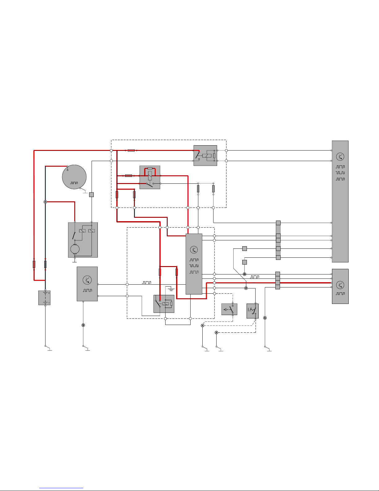
TP39127202 V70(08-), XC70(08-) & S80(07-) 2008 Supplement 69
Group 33 Starting system
Starting system 4 Cyl.
12V
1/1
1(86)
3(30)
1
R12
2/35
15/31
F27
2
CEM
CAN
5(87)
2(85)
1
F23
2
4
GY-BU
RD-BK
RD-BU
GN-VT
GY-BK
C3:49
B:L2
B:L1
B:G2
C5:1
2
3
YE-BU
C3:76
31/3
BK
31/10
BK-WH BK-WH
11A/2
2
11B /3 4
1
1
1
11A /1
2
2
11B/27
1
2
RD
BU-WH
RD
RD
RD
LIN
C1:1
6/26
B+
G
31
2
PF2
1
73/3076
73/4012
M
C2:1
6/25
C1:1
ECM
CAN
LIN
2
PF1
1
ACM
1
3
R8
2/31
5
2
1
11B /2 0
2
1
11B/17
2
4/102
K9
4/46
3/132
4/56
SCL
LIN
C3:71
C5:2
GN-RD
YE
C1:45 C1:65
C1:44
C3:35
C3:50
C3:74
VT-BNVT-BN
S80
LHD
VT-BN
BU-WH
BU-WH
GY
GY
RD-VT
RD-VT
BK
BU-WH
BU BU
BU
VT-OG
VT-BN
VT-OG
C1:37
24
9
18
74/301
74/413
73/4027
73/4016
74/411
74/504
GY-BN
GY-BN
GY-BN
5
SCU
LIN
23
20
5
3
3
1
1
2
2
2
42
C2:27
31/83
BKBK
BK-GN
BK-GN
BK-BU
31/7
73/5071
73/5072
LHD
RHD
2
1
1
2
3/271
BK-BU
31/84
LIN
73/5055
GY-BN
GY-BN
C3:42
VT-BN
4CYL.
B:K1(Diesel),
B:K2(Diesel),
B:G3A:F4(Diesel),
B:E3C:G4(Diesel),
B:J2C:F4(Diesel),
B:J1C:B4(Diesel),
A:C3(Diesel),
BU-WH
74/302
1
3/39
2
3
C2:33
GN-VT
BK-GN
Page 70

TP39127202 V70(08-), XC70(08-) & S80(07-) 2008 Supplement 70
Group 35 Lighting
Running/parking lights, Tail lights V70
LIN
C1:50
C1:49
30+
1
CEM
4/56
2
11A/1211A/2
C2:24
1
1
2
11B/23
15/31
C2:50
RD-BK
RD-BU
BK
BK
BK
RHD
LHD
M
+
-
L
LOW
HIGH
PARK
TURN
M
+
-
L
LOW
HIGH
PARK
TURN
10/1
10/2
10
1
1
10
10/12
10/11
C5:2
C5:1
C1:10
C1:40
C3:52
31/8331/9331/94
GN-OG
GY-RD
WH-OG
VT-GN
CAN
9
74/602
YE-VTYE-VT
C2:52
73/3033
73/4017
73/4016
73/3035
BK-OG
BK
BK-VT
BK-OG
BK-VT
1
6
5
LIN
RD-BK
RD-BK
GN-VT
3/111
74/411
12
LSM
CAN
C1:6
C1:2
5/1
DIM
10/17
10/18
BK-OG
BK-OG
31/48
73/5033
BK-BU BK-BU
TURN
TURN
FOG
FOG
POS
POS
REV
REV
STOP
STOP
TAIL/STOP
TAIL/STOP
GND
GND
GND
GND
C1:4
C2:4
C1:4
C2:4
73/6001
BK-OG
BK-OG
74/602
31/47
73/5105
7
BK-OG
BK-OG
C2:1
C2:1
10/45
10/52
BK-OG
10/3
13
24
2
1
3/35
KVM /
POT
Page 71

TP39127202 V70(08-), XC70(08-) & S80(07-) 2008 Supplement 71
LIN
C1:50
C1:49
30+
1
CEM
4/56
2
11A/1211A/2
C2:24
1
1
2
11B/23
15/31
C2:50
RD-BK
RD-BU
BK
BK
BK
BK
RHD
LHD
10/11
10/12
C5:2
C5:1
C1:10
C1:40
C3:52
31/8331/9331/94
GN-OG
GY-RD
WH-OG
CAN
YE-VT
VT-GN
C2:52
73/3033
73/4017
73/4016
73/3035
BK-OG
BK-VT
BK-OG
BK-VT
1
6
5
LIN
RD-BK
RD-BK
GN-VT
3/111
74/411
12
LSM
CAN
C1:6
C1:2
5/1
DIM
10/1
TURN POS HIGH LOW
1
10 10
M
10/2
TURN POS HIGH LOW
M
1
10/17
10/18
BK-OG
BK-OG
31/48
73/5033
BK-BU BK-BU
TURN
TURN
FOG
FOG
POS
POS
REV
REV
STOP
STOP
TAIL/STOP
TAIL/STOP
GND
GND
GND
GND
C1:4
C2:4
C1:4
C2:4
73/6001
BK-OG
BK-OG
74/602
31/47
73/5105
7
BK-OG
BK-OG
C2:1
C2:1
10/45
10/52
9
74/602
YE-VT
BK-OG
10/3
13
24
2
1
3/35
KVM /
POT
Group 35 Lighting
Running/parking lights, Tail lights (Bi-Xenon) V70
Page 72
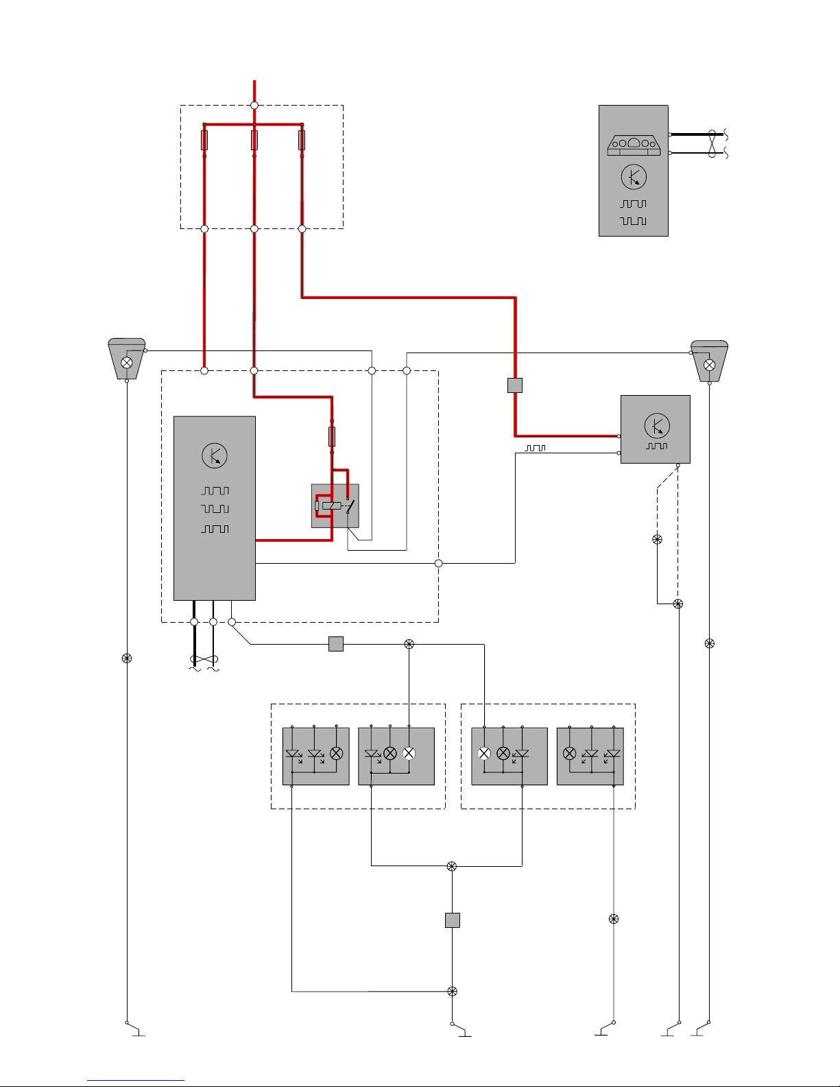
TP39127202 V70(08-), XC70(08-) & S80(07-) 2008 Supplement 72
CAN
C1:6
C1:2
5/1
DIM
73/3033
BK-OG
BK-OG
11B/2311A/2
2 2
30+
1 1
2
1
31/93
2
10/5
1
BU-RD
YE-OG
CAN
4/56
CEM
LIN
11A/1
31/94
73/3035
BK-VT
BK-VT
2
10/6
1
31/83
C2:39
C5:2 C1:69 C1:68C5:1
15/31
RD-BK
RD-BU
BK
K1
F13
2
1
BK
BKBK
RHD
LHD
C3:52
73/4017
73/4016
1
6
5
LIN
RD-BK
RD-BK
GN-VT
3/ 111
74/411
12
LSM
WH-BU
BN-GN
RHD
LHD
C1:50
C1:49
10/17
10/18
BK
BK-OG
BK-OG
WH-BU
31/48
73/5033
BK-BU BK-BU
73/6004
TURN
TURN
FOG
FOG
POS
POS
REV
REV
STOP
STOP
TAIL/STOP
TAIL/STOP
GND
GND
GND
GND
C1:4
C2:4
C1:4
C2:4
73/6001
BK-OG
BK-OG
74/602
31/47
73/5105
7
BK-OG
BK-OG
C1:2
C1:2
10/46
10/53
74/602
5
Group 35 Lighting
Fog lights, V70
Page 73

TP39127202 V70(08-), XC70(08-) & S80(07-) 2008 Supplement 73
2
1
3/9
4/93
4
2
10/17
10/18
73/5089
BK-OG
CAN
C1:50
C1:49
30+
1
CEM
4/56
CAN
KVM
2
11A/2
2
11A/1
2
F28
C5:1
C5:2
C2:66
C2:54
C2:34
C2:38
1
1
RD-WH
VT-WH VT-WH
C5:14
YE-GY
15/31
C2:59
RD-BU
RD-BK
LIN
BK-OG
BK-OG
VT-BN
BK
GY-BN
31/48
73/5033
BK-BU BK-BU
73/6002
VT-BN
TURN
TURN
FOG
FOG
POS
POS
REV
REV
STOP
STOP
TAIL/STOP
TAIL/STOP
GND
GND
GND
GND
74/602
2
BK
C1:4
C2:4
C1:4
C2:4
C2:3
73/6001
BK-OG
BK-OG
74/602
31/47
73/5105
7
BK-OG
BK-OG
C1:3
C1:3
C2:3
GY-BN
GY-BN
10/43
10/50
10/51
10/44
74/602
3
GY-BN
10/19
Group 35 Lighting
Brake light, V70
Page 74
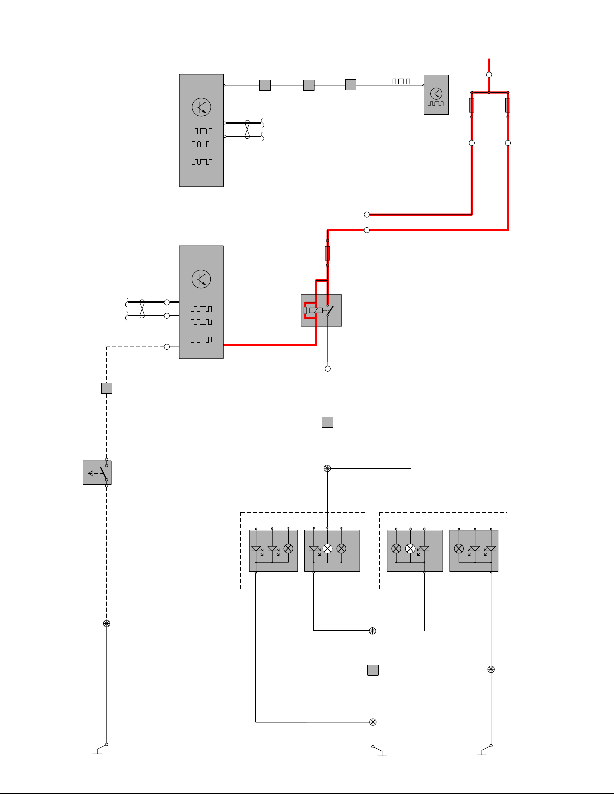
TP39127202 V70(08-), XC70(08-) & S80(07-) 2008 Supplement 74
BK-YE
CAN
C3:48
C3:47
A:14
A:6
TCM
4/28
30+
11A/2
2
11
2
11A /1
BK-YE
MAN
MAN
MAN
BU
BU
74/301
31/XX10
C1:26
4/56
CEM
3/10
1
2
LIN
CAN
LIN
1
2
F11
15/31
C2:73
C5:2
C5:1
K3
3/156
A:7
74/411
BN-VT BN-VT BN-VT BN-VT
10
74/301
11
74/403
22
A:2
LIN
GSM
AUTO
RD-BU
RD-BK
73/3094
GN-BN
19
GY-VT
10/17
10/18
BK
BK-OG
BK-OG
GY-VT
31/48
73/5033
BK-BU BK-BU
73/6003
TURN
TURN
FOG
FOG
POS
POS
REV
REV
STOP
STOP
TAIL/STOP
TAIL/STOP
GND
GND
GND
GND
C1:4
C2:4
C1:4
C2:4
73/6001
BK-OG
BK-OG
74/602
31/47
73/5105
7
BK-OG
BK-OG
C1:1
C1:1
10/48
10/55
74/602
4
Group 35 Lighting
Reversing lights, V70
Page 75

TP39127202 V70(08-), XC70(08-) & S80(07-) 2008 Supplement 75
Group 35 Lighting
Door handle lighting LHD
LIN
30+
1
CEM
4/56
15/32
2
11A/3
2
11A/2
C5:1
C5:2
1
15/31
RD-GNRD-GNRD-GN
RD-BU
1
2
11A/1
RD-BK
2
11D/A1
1
2
11D/A2
1
20
21
4
74/507
3X/19
73/5019
73/5075
31/6
31/15
73/5035
73/5023
73/5024
BK-VTBK-VT
BK-VT
BK-GN
GN-BK
CAN
2
74/504B
20
21
4
74/508
DDM
3/126
C1:13
C1:2
C1:20
BK-VT BK-VT
GN-WH
RD RD
GN-WH
PDM
3/127
C1:13
C1:2
C1:20
RD-BK
GN-WH
RD-BK
73/5037
UNLOCK
LOCK
3/82
43
2
-
+
5
1
UNLOCK
LOCK
3/80
10/241
10/242
10/244
10/243
43
2
+
-
2
1
5
1
C2:21
C1:4
C1:18
C2:5
C1:4
C2:21
C2:20
C2:5
GY-VT
BK-BU
VT
OG
GY
GN-RD
-VT
VT-BK
VT
VT
VT
GY-RD
GY-RD
GY-RD
GN-BN
YE
YE
YE
YE
VT-GY
GN-BN
GN-BN
GY-YE
GN-BN
GN-BN
GY-YE
VT-GY
YE
YE
BK-GNBK-GN
KEYLESS KEYLESS
BK-GN
C2:15
C2:3
C1:50
C1:49
C2:15
C2:3
CAN
LIN
CAN
LIN
2 1345
3X/80
2
11D/A3
1
2
11D/A4
1
4 132
3X/82
2
1
2
1
4
5
3
2
1
3/83
5
2
1
2
20
LIN
3/128
LDM
74/509
RD-BU
BK-VT
BK-VT
BK-VT
RD-BU
13
4
BU-OG
GY-OG
YE YE
BU-BK BU-BK
BU-BK
BU-OG
BU-BK
GY-OG
GY-OG
GY-OG
22 11 18
6
5
2
+
1
-
3/19
5
6 3 4
2
1
5
6 3 4
2
1
RDM
LIN
4
3/129
2
12
74/510
3X/21
RD-GN
BK-GN
RD-GN
GY-VT
VT-RD
GN-RD
GN-BU
GY-OG
GN
YE
GY-OG
BU-BK
BU-BK
BU-OG
BU-BK
GY-OG
20
22 11
18
6
3
OG
4
5
2
1
-
+
3/21
GN3OG
4
1
2
BK-RD
C1:54
BK-RD
KEYLESS
KEYLESS
73/3030
73/5036
31/96
BK-GN
BK-GN
BK-GN
13
KEYLESS
KEYLESS
73/5025
Page 76
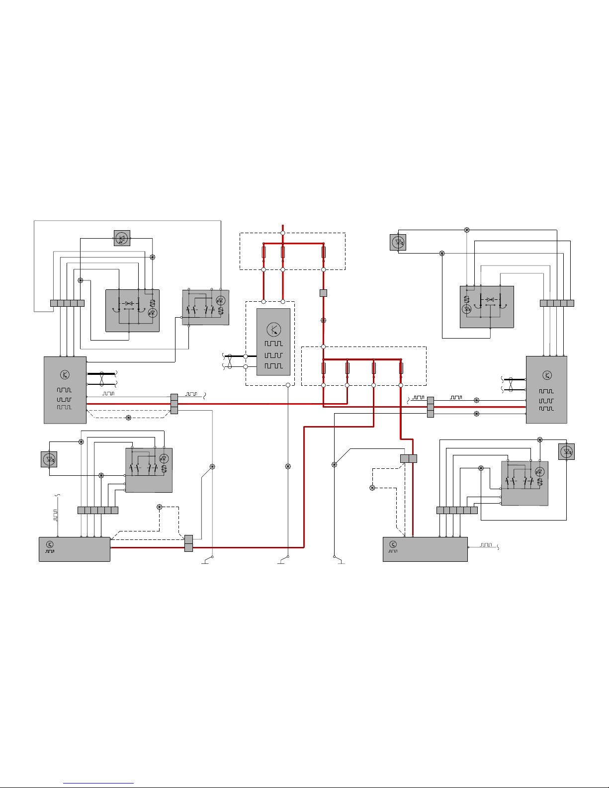
TP39127202 V70(08-), XC70(08-) & S80(07-) 2008 Supplement 76
Group 35 Lighting
Door handle lighting RHD
LIN
30+
1
CEM
4/56
15/32
2
11A/3
2
11A/2
C5:1
C5:2
1
15/31
RD-GNRD-GNRD-GN
RD-BU
1
2
11A/1
RD-BK
2
11D/A1
1
2
11D/A2
1
20
21
4
74/507
3X/19
73/5075
31/6
31/15
73/5035
73/5023
73/5037
73/5019
BK-VTBK-VT
BK-VT
BK-GN
GN-BK
CAN
2
74/504B
20
21
4
74/508
PDM
3/127
C1:13
C1:2
C1:20
BK-VT
BK-VT
BK-VT
RD-BK RD-BK
GN-WH
DDM
3/126
C1:13
C1:2
C1:20
RD
GN-WH
RD
73/5024
UNLOCK
LOCK
3/80
43
2
-
+
5
1
UNLOCK
LOCK
3/82
10/241
10/242
10/244
10/243
43
2
+
-
2
1
5
1
C2:21
C2:20
C1:4
C1:18
C2:5
C1:4
C2:21
C2:5
GY-VT
BK-BU
VT
OG
GY-YE
GN-BN
VT-GY
YE
VT
VT
GY-RD
GY-RD
GY-RD
GN-BN
YE
YE
YE
YE
VT-GY
GN-BN
GN-BN
GY-YE
GN-RD
GN-BN
GY-VT
VT-BK
VT
YE
BK-GNBK-GN
C2:15
C2:3
C1:50
C1:49
C2:15
C2:3
CAN
LIN
CAN
LIN
2 1345
3X/82
2
11D/A3
1
2
11D/A4
1
4 132
3X/80
2
1
2
1
4
5
3
2
1
3/83
5
2
1
2
20
LIN
3/128
LDM
74/509
RD-BU
BK-VT
BK-VT
BK-VT
RD-BU
13
4
BU-OG
GY-OG
YE YE
BU-BK BU-BK
BU-BK
BU-OG
BU-BK
GY-OG
GY-OG
GY-OG
22 11 18
6
5
2
+
1
-
3/19
5
6 3 4
2
1
5
6 3 4
2
1
RDM
LIN
4
3/129
2
12
74/510
3X/21
RD-GN
BK-GN
RD-GN
GY-VT
VT-RD
GN-RD
GN-BU
GY-OG
GN
YE
GY-OG
BU-BK
BU-BK
BU-OG
BU-BK
GY-OG
20
22 11
18
6
3
OG
4
5
2
1
-
+
3/21
GN3OG
4
1
2
BK-GN
C1:54
BK-GN
KEYLESS
KEYLESS
73/3036
73/5036
31/95
BK-GN
BK-GN
BK-GN
13
KEYLESS
KEYLESS
KEYLESSKEYLESS
73/5025
Page 77

TP39127202 V70(08-), XC70(08-) & S80(07-) 2008 Supplement 77
74/508
73/5023
31/10
20
BK-WH
BK-WH
LIN
LIN
3/6
C3:8
10
3
5
1
C3:41
GY-OG
GN-OG
GN-OG
C5:1
4/56
CEM
GY-RD
11A/1
2
1
30+
y
M
x
M M
F
6/63
MEM
X
MEM
Y
CAN
PDM
C5:2
11A/2
2
1
11A/3
2
1
11D/A1
2
1
11D/A2
2
15/31
15/32
1
74/504B
74/508
C2:11
C2:23
C2:3
C2:15
DDM
74/507
21
C2:23
C2:11
CAN
RD
RD-GN
RD-GN
RD-GN
RD-BK
RD-BK
RD
C1:2C1:2
3/127
3/126
YE-VT
BU-GN
C2:18 C1:1C2:36C1:19
31/94
31/15
BK-GNBK-GN
BK-GN
KEYLESS
BK-GN KEYLESS
BK-GN
C1:13
74/507
20
31/6
BK-VT
BK-VT
BK-VT
BK-VT
31/93
BK-OG BK-OG
C1:13
y
M
x
M M
F
6/62
MEM
X
MEM
Y
M
-
+
L
HIGH
LOW
PARK
TURN
10/1
10
10/13
M
-
+
L
LOW
HIGH
PARK
TURN
10/2
10
10/14
10/16
10/15
2
2
BK
BK-BU
RD-BK
RD-BU
BK
BK-BU
CAN
73/3035
BK-VTBK-VT
73/3033
C2:3
C2:15
CAN
LIN
3/130
SWM
C1:7
C1:20
73/5075
73/5024
2
21
C1:20
612
6
12
LIN
73/5035 73/5037
73/4012
DIM
C1:6
C1:2
5/1
CAN
10/17
10/18
BK-OG
BK-OG
31/48
73/5033
BK-BU BK-BU
TURN
TURN
FOG
FOG
POS
POS
REV
REV
STOP
STOP
TAIL/STOP
TAIL/STOP
GND
GND
GND
GND
C1:4
C2:4
C1:4
C2:4
73/6001
BK-OG
BK-OG
74/602
31/47
73/5105
7
BK-OG
BK-OG
C2:2
C2:2
10/54
10/47
Group 36 Other electrical equipment
Direction indicator and Hazard warning flashers LHD, V70
Page 78

TP39127202 V70(08-), XC70(08-) & S80(07-) 2008 Supplement 78
74/507
73/5035
31/10
20
BK-WH
BK-WH
LIN
LIN
3/6
C3:8
10
3
5
1
C3:41
GY-OG
GN-OG
GN-OG
C5:1
4/56
CEM
GY-RD
11A/1
2
1
30+
y
M
x
M M
F
6/62
MEM
X
MEM
Y
CAN
PDM
C5:2
11A/2
2
1
11A/3
2
1
11D/A1
2
1
11D/A2
2
15/31
15/32
1
74/504B
74/507
C2:11
C2:23
C2:3
C2:15
DDM
74/508
21
C2:23
C2:11
CAN
RD-GN
RD-GN
RD-GN
RD-BK
RD
RD-BK
RD
C1:2C1:2
3/127
3/126
YE-VT
BU-GN
C2:18 C1:1C2:36C1:19
31/94
31/6
BK-VTBK-VT
BK-VT
KEYLESS
BK-VT
KEYLESS
BK-VT
C1:13
74/508
20
31/15
BK-GN
BK-GN
BK-GN
BK-GN
31/93
BK-OG BK-OG
C1:13
y
M
x
M M
F
6/63
MEM
X
MEM
Y
M
-
+
L
HIGH
LOW
PARK
TURN
10/1
10
10/13
M
-
+
L
LOW
HIGH
PARK
TURN
10/2
10
10/14
10/16
10/15
2
2
BK
BK-BU
RD-BK
RD-BU
BK
BK-BU
CAN
73/3035
BK-VT
BK-VT
73/3033
C2:3
C2:15
CAN
LIN
3/130
SWM
C1:7
C1:20
73/5075
73/5024
2
21
C1:20
612
6
12
LIN
73/5023 73/5037
73/4012
DIM
C1:6
C1:2
5/1
CAN
10/17
10/18
BK-OG
BK-OG
31/48
73/5033
BK-BU BK-BU
TURN
TURN
FOG
FOG
POS
POS
REV
REV
STOP
STOP
TAIL/STOP
TAIL/STOP
GND
GND
GND
GND
C1:4
C2:4
C1:4
C2:4
73/6001
BK-OG
BK-OG
74/602
31/47
73/5105
7
BK-OG
BK-OG
C2:2
C2:2
10/54
10/47
Group 36 Additional electrical equipment
Direction indicator and Hazard warning flashers RHD, V70
Page 79

TP39127202 V70(08-), XC70(08-) & S80(07-) 2008 Supplement 79
Group 36 Additional electrical equipment
High-pressure headlight washer
30+
1
11B/24
73/3035
74/309
2
C1:48
GN-VT
YE-GN
BK-OG YE-OG
BU-BK
C1:47
31/94
CEM
CAN
4/56
15/31
LIN
BK-VT BK-VT
YE-RD
BK-VT
BU-BK
YE-GN
BK-GN
6/104
6/144
6/145
1(86)
3(30)
2/193
2(85)
R9
5(87)
7 2 1
1
2
438
567
2
1
2
1
11B /27
2
3/130
GN-BK
C3:51
C1:7
LIN
SWM
18/4
WIPER
TURN
Page 80

TP39127202 V70(08-), XC70(08-) & S80(07-) 2008 Supplement 80
RD-GY
GY-BN
30+
RD-BK
RD-GY
1
2
11A/1
15/31
4/56
2
11A/2
1
K10-A
1
2
C2:74
C5:1
F20
CAN
CEM
LIN
15/32
52
3
1
RA2
2/16
C2:44
74/602
8
14
7
31/47
73/5105
73/6001
VT-GN
GY-BU
BK-OG
BK-OG
BK
BK
BK-OGBK-OG
6/32
2
1
3
RD-BU
C5:2
4
BK-OG
3/130
GN-BK
C3:51
C1:7
LIN
SWM
18/4
WIPER
TURN
Group 36 Additional electrical equipment
Wiper/washer rear window, V70
Page 81

TP39127202 V70(08-), XC70(08-) & S80(07-) 2008 Supplement 81
15
1
14
13
15
16
17
12
15
2
4
6
5
3
11A/2
2
1
30+
15/31
C2:2
C5:1
C5:2
4/56
31/48
CAN
CEM
PAM
4/86
CAN
11A/1
2
1
C3:11
C3:8
C1:8
C3:5
C3:3
C3:2
C3:4
BU-WH
YE-OG
YE-GY
YE-BK
YE-GN
BK-GN
BK-BU
RD-BU
RD-BK
GN-WH
BU-WH BU-WH
BU-WH
BU-WH
BU-WH
YE-OG
YE-GY
YE-BK
YE-GN
GN-WH GN-WH
GN-WH
GN-WH
GN-WH
73/5064
7/134 RR/O
RR/I
LR/I
LR/O
7/133
7/132
7/131
1
3
2
1
3
2
1
3
2
1
3
2
1
73/5067
73/5033
74/523
74/519
74/309
73/3046
73/3047
llll
7/2047/207
1 23123 123 123
7/206 7/205
YE-OG
C2:1
BU-GN
C2:5
BU-BK
C2:6
BU-GY
C2:7
BU-OG
C2:8
VT-GY
YE-OG
BU-GN
BU-BK
BU-GY
BU-OG
VT-GY
YE-OG
VT-GY
YE-OG
BU-OG
VT-GY
YE-OG
BU-GY
VT-GY
YE-OG
BU-BK
VT-GY
YE-OG
BU-GN
VT-GY
C2:2
RF/O RF/I LF/I LF/O
6
5
10
11
12
4
C1:1
BU-RD
73/5106
C1:50
C1:49
C1:7
C1:14
BU-RD
Group 36 Additional electrical equipment
Parking assistance
Page 82

TP39127202 V70(08-), XC70(08-) & S80(07-) 2008 Supplement 82
Group 36 Additional electrical equipment
Keyless vehicle 4 Cyl. 1:2
SIGNAL
POWER
GND
4/119
RKE
30+
1
2
11 A / 2
1
2
11 A / 1
1
2
11 A / 4
4/93
KVM
CAN
LIN
LIN
LIN
15/31
C5:1 C5:2
132
C4:16
C4:4
BK-WH
BK-WH
BK-WH
BU
VT-WH
VT-WH
BU-WH BU-WH
RD-VT
GY-BN
RD-BN
GY-BN
BK-WH
GY-BN
31/7 31/47 31/67
RD-BK
RD-GYRD-GYRD-GY
CAN
4/5615/32
4/46
CEM
CAN
ECM
C2:40
C3:35 C2:54C2:27
I4 B:B4
Diesel A:A3
I4 B:A4
Diesel A:A4
BK
GY-BN
BU-RD
GY-BN GY-BN
MAN
MAN
MAN
RHD
LHD
BK-GN
BK-BU
BK-GN
BKBK-OG
BK-GN
BK-OG
RD-BU
10/3
3/35
3
1
C4:3
C4:4
C4:15
C4:14
C5:14
C5:18
C3:4
BK-GN
2
1
74/601
1
2
3/271
11D/B10
74/301
1
2
B:J2 (I4)
C:F4(Diesel)
1
74/504B
73/5040
73/4014
73/4012
73/4027
73/5105
73/5029
74/601
73/5071
74/414
74/409
31/10
2
C3:5
C5:3
25
3
4
20
74/504
42
31/84
BK-BU
73/5072
2
1
3/9
73/5055
GY-BN
MANMAN
GY-BN
S80
S80
F21
12
4 CYL.
Page 83
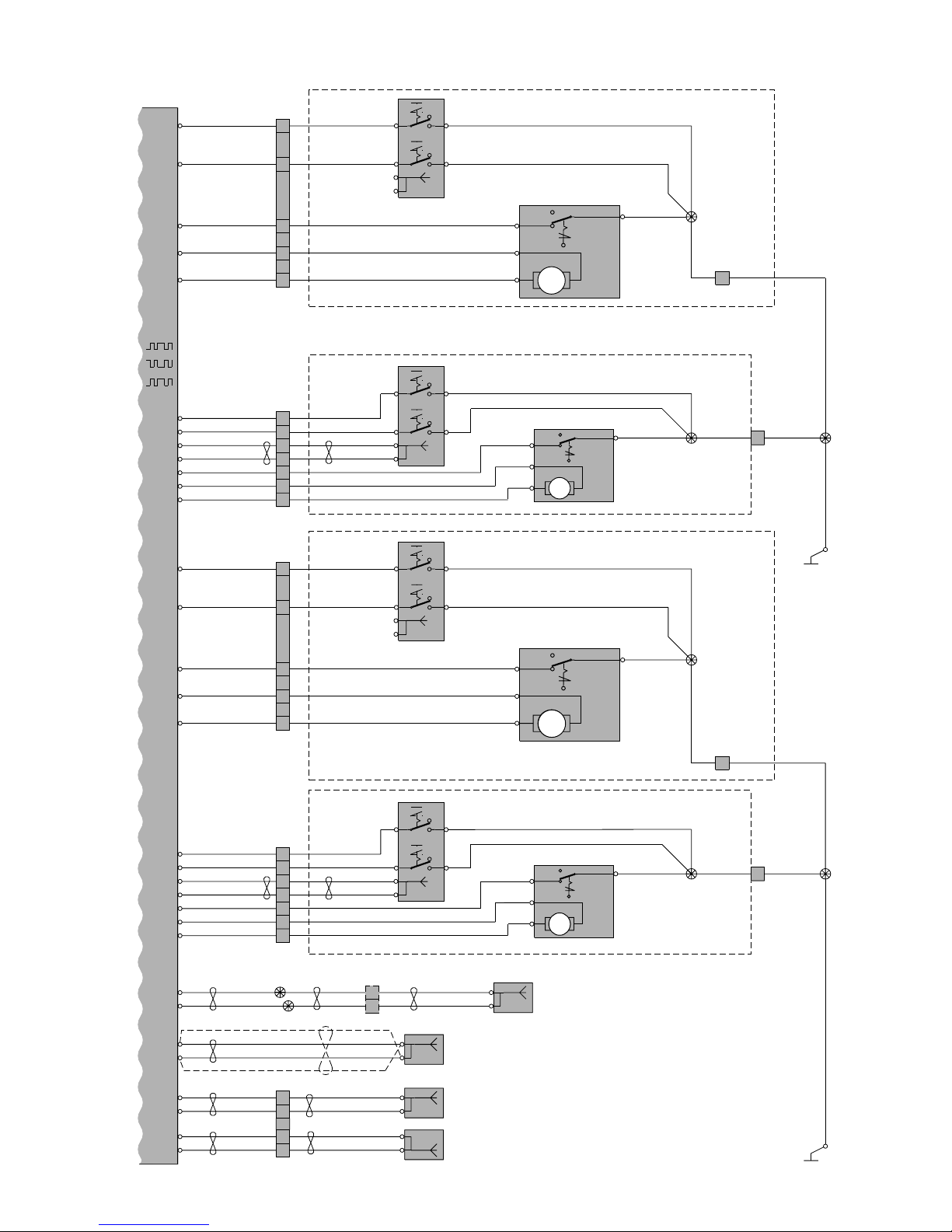
TP39127202 V70(08-), XC70(08-) & S80(07-) 2008 Supplement 83
4/93
KVM
CAN
LIN
C5:2
C5:22
C4:22
C4:2
C2:5
GN-RD
BU-GY
GY-BN
GN-VT
BK-GN
BK-GN
BK-GN
BK-GN
BK-GNBK-GNBK-GN
BK-GN
BK-GN
BK-GN
BK-GN
BU-RD
GN-RD
BU-GY
GY-BN
GN-VT
BU-RD
PASSENGER DOOR LHD
DRIVER DOOR RHD
REAR RIGHT DOOR
DRIVER DOOR LHD
PAS SENGER DOOR RHD
REAR LEFT DOOR
21
1
2
63
3/276
1
6/55
11
74/508
12
14
15
13
C5:5
C5:20
C1:14
C4:21
C2:3
C3:1
C1:23
VT-RD
GY-RD
BU-OG
YE-RD
GN
GY-BK
VT-GY
VT-RD
GY-RD
BU-OG
YE-RD
GN
GY-BK
VT-GY
13
74/510
14
9
12
11
8
10
C5:17
C5:4
C1:15
C5:15
C2:2
C3:2
C1:3
GY-OG
GN-OG
YE
YE
VT-OG
YE-BU
BU-BN
GN-BN
GY-OG
GN-OG
VT-OG
YE-BU
BU-BN
GN-BN
13
74/509
14
9
12
11
8
10
C1:18
C1:2
C2:14
C1:16
C1:4
C2:17
YE-BK
BN-VT
GY-VT
YE-OG
GN-RD
BU-WH
GY-VT
YE-OG
GN-RD
BU-WH
C1:21
C1:22
GN-OG
VT
3
74/501
4
6
5
16/132
1
2
P1
P2
2
16/133
1
P1
P2
16/134
1
2
P1
P2
16/135
1
2
P1
P2
4
5
P1
P2
73/5024 LHD
73/5037 RHD
4
2
1
3
6/56
12
LOCK
UNLOCK
RELEASE
CLUTCH
73/5025
1
4
3
2
6/57
12
LOCK
UNLOCK
RELEASE
CLUTCH
73/5036
4
2
3
12
LOCK
UNLOCK
RELEASE
CLUTCH
C5:19
C5:21
C4:9
C4:1
C2:4
BU-GN
YE-VT
GN-WH
VT-BK
BK-VT
BK-VT
BK-VT
BK-VT
BK-VTBK-VTBK-VT
BK-VT
BK-VT
BK-VT
BK-VT
GY
BU-GN
YE-VT
GN-WH
VT-BK
GY
3
6/36
11
74/507
12
14
15
13
73/5037 LHD
73/5024 RHD
1
4
2
12
M
M
M
M
LOCK
UNLOCK
RELEASE
CLUTCH
20
74/508
20
74/507
2
74/510
73/5023
31/15
2
74/509
73/5035
31/6
1
2
2
1
1
2
63
3/274
4
5
P1
P2
1
2
21
1
2
63
3/275
4
5
P1
P2
1
2
2
1
1
2
63
3/273
5
4
P1
P2
1
2
M
M
16
74/603
15
V70
GN-OG
VT
YE-BK
BN-VT
V70
V70
S80
S80
73/5110
73/5109
V70
GN-OG
VT
V70
Group 36 Additional electrical equipment
Keyless vehicle 4 Cyl. 2:2
Page 84

TP39127202 V70(08-), XC70(08-) & S80(07-) 2008 Supplement 84
C3:48
C3:47
CEM
11A /1
2
11
11A/2
2
1
11B/18
2
1
F15
2
R8
2/31
15/31
4/80
4/56
K10-A
27/2
7/203
1
11B/27
2
31
25
30+
C1:45 C5:2 C5:1
C3:55
C1:2
BU-BK
C1:12
1
YE-RD
GY-OG
GY-OG
GY-BU
GY-OG
GY-OG
GY-OG
GN-VT
RD-BU
RD-BK
73/3052
74/411
LHD
RHD
CAN
LIN
FSM
CAN
C1:11
YE-RD
GY-BU
C1:6
C1:7
FLR
CAN
5
1
43
C1:8
C1:9
4
BK
BK
BK
C1:10
53
2
31/96
BK-RDBK-RD
31/83
BK
73/3030
73/4017
73/4016
C1:3
GN-BN
2
C1:4
BU-GN
3
C1:15
VT
4
GY-VT
C1:1
C1:2
C1:3
C1:4
C1:5
C1:6
74/418
WH
BN
PK
YE
GY
GN
27/5
1
2
3
4
5
6
C1:S
S
C2:1
C2:2
C2:3
C2:4
C2:5
C2:6
WH
BN
PK
YE
GY
GN
C2:S
GY-OG
GY-OG
W/OFLR
RHD
9/39
GY-BK
1
GY-BK
2
+
-
C1:1
C1:14
FLC
74/412
7
9
BK
BK
Group 36 Additional electrical equipment
Collision warning with brake servo
Page 85

TP39127202 V70(08-), XC70(08-) & S80(07-) 2008 Supplement 85
11A/2
2
1
30+
1
2
11A/1
CAN
CEM
4/56
4/119.2
31/10
73/4012
C5:1 C5:2
LIN
RD-BK
RD-BU
15/31
GY-BN
2
1
3
BK-WH
BU-WH
BU-WH
RD-BN
GY-BN
BK-WH BK-WH
C4:16
C4:4
RD-BN
RD
RD RDBKBK BK
RRX
LIN
74/412
23
1
2
F21
1
2
F17
C2:17
C2:40
GY-BN
K10-A
12
C1:50
C1:49
C3:67
73/4019
12
12
17/45
7/238
26/8
10X/29
10/29
CAN
C1:6
C1:2
5/1
DIM
Group 36 Additional electrical equipment, Accessories
Alcolock
Page 86
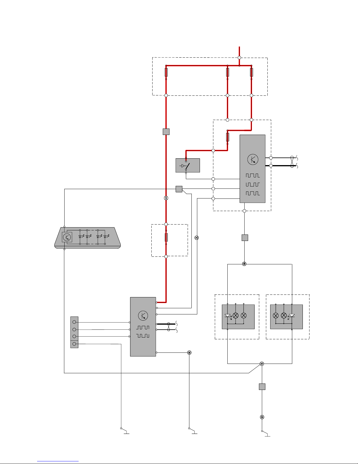
TP39127202 V70(08-), XC70(08-) & S80(07-) 2008 Supplement 86
Group 37 Wiring and fuses, Accessories
Tow hitch cable harness, 4-pin V70
1
2
3/9
CAN
C1:50
C1:49
30+
1
CEM
4/56
31/6531/TRM
2
11A/1
2
11A/2
2
F28
11D/A11
C5:2
C5:1
C2:66
C2:54
C2:2
C2:59
1
1
RD-WH
VT-WH
15/31
15/32
RD-BK
RD-BU
2
1
CAN
4/110
TRM
C3:7
C2:1
C2:2
C2:5
C2:4
C1:2
C2:3
GN
1
2
11A/3
RD-GNRD-GNRD-GNRD-BK
BU-RD
74/504B
73/5075
2
2
GY-BN
BK-OG
LIN
17/37
1
2
3
4
WH
C3:3
C3:12
YE
BN
73/5030
BK-OG
73/5106
BU-RD
4
2
10/19
C2:34
YE-GY
BK
YE-GY
74/602
BK-OG
10/17
10/18
BK-OG
VT-BN
BK
73/6002
VT-BN
FOG
FOG
REV
REV
STOP
STOP
GND
GND
C1:4
C1:4
73/6001
BK-OG
BK-OG
74/602
31/47
73/5105
7
BK-OG
BK-OG
C1:3
C1:3
10/43
10/50
74/602
3
Page 87
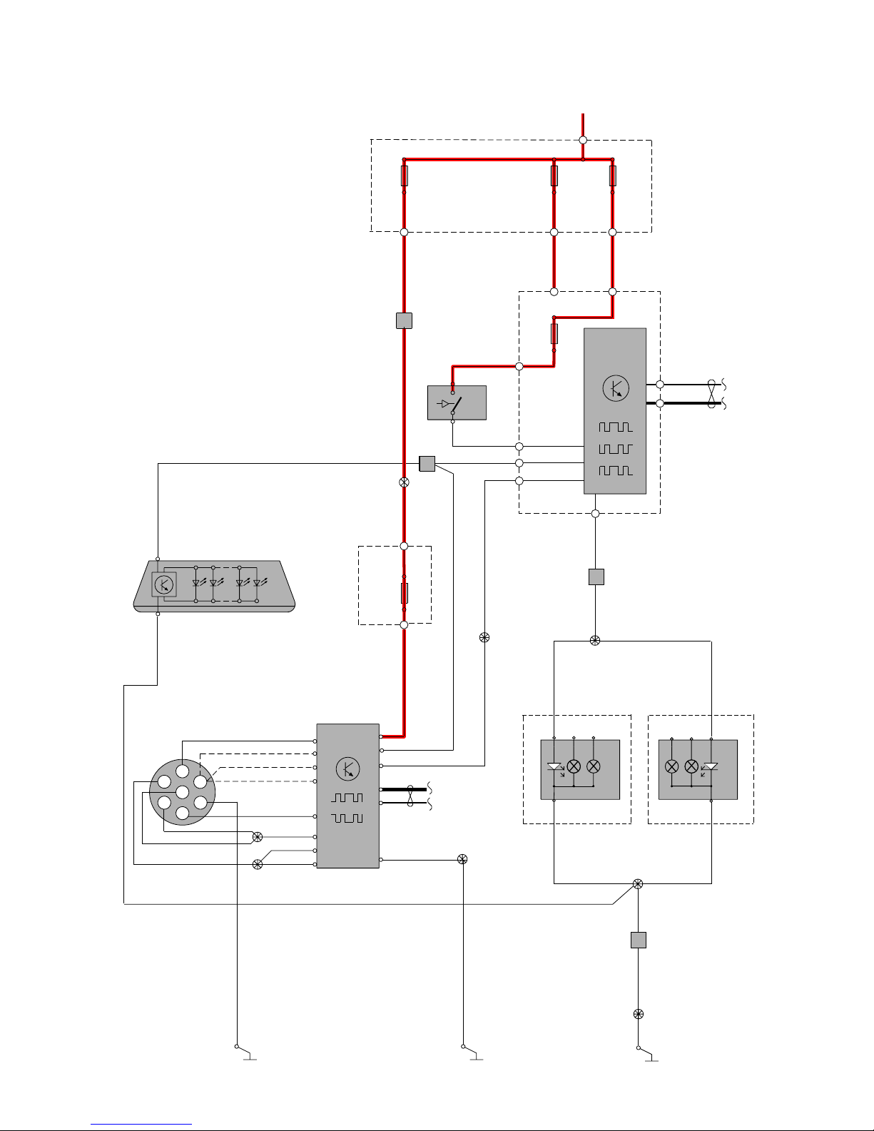
TP39127202 V70(08-), XC70(08-) & S80(07-) 2008 Supplement 87
Group 37 Wiring and fuses, Accessories
Tow hitch cable harness, 7-pin V70
31/65
GY-BN
BK-OG
BK
73/5030
BK-OG
4
2
10/19
10/17
10/18
BK-OG
VT-BN
BK
73/6002
VT-BN
FOG
FOG
REV
REV
STOP
STOP
GND
GND
C1:4
C1:4
73/6001
BK-OG
BK-OG
74/602
31/47
73/5105
7
BK-OG
BK-OG
C1:3
C1:3
10/43
10/50
74/602
3
1
2
3/9
CAN
C1:50
C1:49
30+
1
CEM
4/56
2
11A/1
2
11A/2
2
F28
11D/A11
C5:2
C5:1
C2:66
C2:54
C2:2
C2:59
1
1
RD-WH
VT-WH
15/31
15/32
RD-BK
RD-BU
2
1
CAN
4/110
TRM
C3:10
C3:2
C3:6
C3:8
C3:1
C3:12
C3:3
C3:7
C2:1
C2:2
C2:3
C2:4
C1:2
C2:5
1
2
11A/3
RD-GNRD-GNRD-GNRD-BK
BU-RD
74/504B
73/5075
2
WH
BU
BU
GN
BN
RD
RD
BU
YE
RD
BK
BN
BK-OG
YE-GY
YE-GY
LIN
31/TRM
17/38
6
7
3
2
1
5
4
73/5106
BU-RD
C2:34
74/602
2
Page 88

TP39127202 V70(08-), XC70(08-) & S80(07-) 2008 Supplement 88
Group 37 Wiring and fuses, Accessories
Tow hitch cable harness, 13-pin V70
31/65
GY-BN
BK-OG
73/5030
BK-OG
4
2
10/19
10/17
10/18
BK-OG
VT-BN
BK
73/6002
VT-BN
FOG
FOG
REV
REV
STOP
STOP
GND
GND
C1:4
C1:4
73/6001
BK-OG
BK-OG
74/602
31/47
73/5105
7
BK-OG
BK-OG
C1:3
C1:3
10/43
10/50
74/602
3
BK-OG
1
2
3/9
CAN
C1:50
C1:49
30+
1
CEM
4/56
2
11A/1
2
11A/2
2
F28
11D/A11
C5:2
C5:1
C2:66
C2:54
C2:2
C2:59
1
1
RD-WH
VT-WH
RD-GN
BU-RD
BU-RD
15/31
15/32
RD-BK
RD-BU
2
1
1
11D/A9
2
CAN
4/110
TRM
C3:10
C3:12
C3:6
C3:7
C3:3
C3:1
C3:8
C3:2
C2:1
C2:2
C2:3
C2:4
C1:2
C2:5
1
2
11A/3
RD-GNRD-GNRD-GNRD-BK
YE-GY
74/504B
73/5075
2
WHWH
WH
WH
WH
WH
WH
WH
WH
WH
WH
WH
WH
WH
WH
WH
YE-GY
LIN
BK
31/TRM
17/39
8
97
6 10
115
13 12
1
3
24
WH
RESERVE:
INDICATION TRAILER
73/5106
74/602
2
C2:34
Page 89

TP39127202 V70(08-), XC70(08-) & S80(07-) 2008 Supplement 89
Group 38 Instruments
Driver information module
DIM
1
C1:2
C1:6
73/4017
73/4016
7/73
7/5
2
2
1
C1:8
5/1
C1:3
C1:1
1
CAN
C1:16
C1:17
3/47
2
30+
15/31
2
11A/1
1
2
11A/2
1
RD-BK
RD-BU
1
2
F18
C5:1 C5:2
C1:25
C1:11
CEM
CAN
LIN
4/56
GN-BU
C2:48
C2:30
C3:48
C3:47
C1:50
C1:49
YE-VT
C2:56
BU-WH
C3:69
C3:11
C1:27
RD-WH
K10-A
7/4
1
2
73/3030
VT
GY-BU
GY-BU
GY-BU
BK-GN
GY-VT
BK
BK
BK
BK
BK-OG
BK
BK
BK-RD
74/511
73/3036
18
19
31/8331/9631/95
14
74/409
M
6/33
436 251
GN-OG AWD
RHD
LHD
GN-BU
YE-VT
BK-GN BK-GN
7/143
7/130
20
CAN
4/115
PBM
73/3033
BK-OG
31/93
LHD
LHD
26/5
YE-VT
GN-BU
YE-VT
BU-WH
GN-BU
18
21
19
74/511B
1918
LEVEL-
μ
PWM
74/511A
73/5044
C2:43
31/66
M
6/33
436 251
GN-BU
YE-VT
BK-YE
7/143
7/130
PEM
BU-WH
FlexiFuel
1
2
F17
YE-VT
GN-BU
GN-OG
Page 90
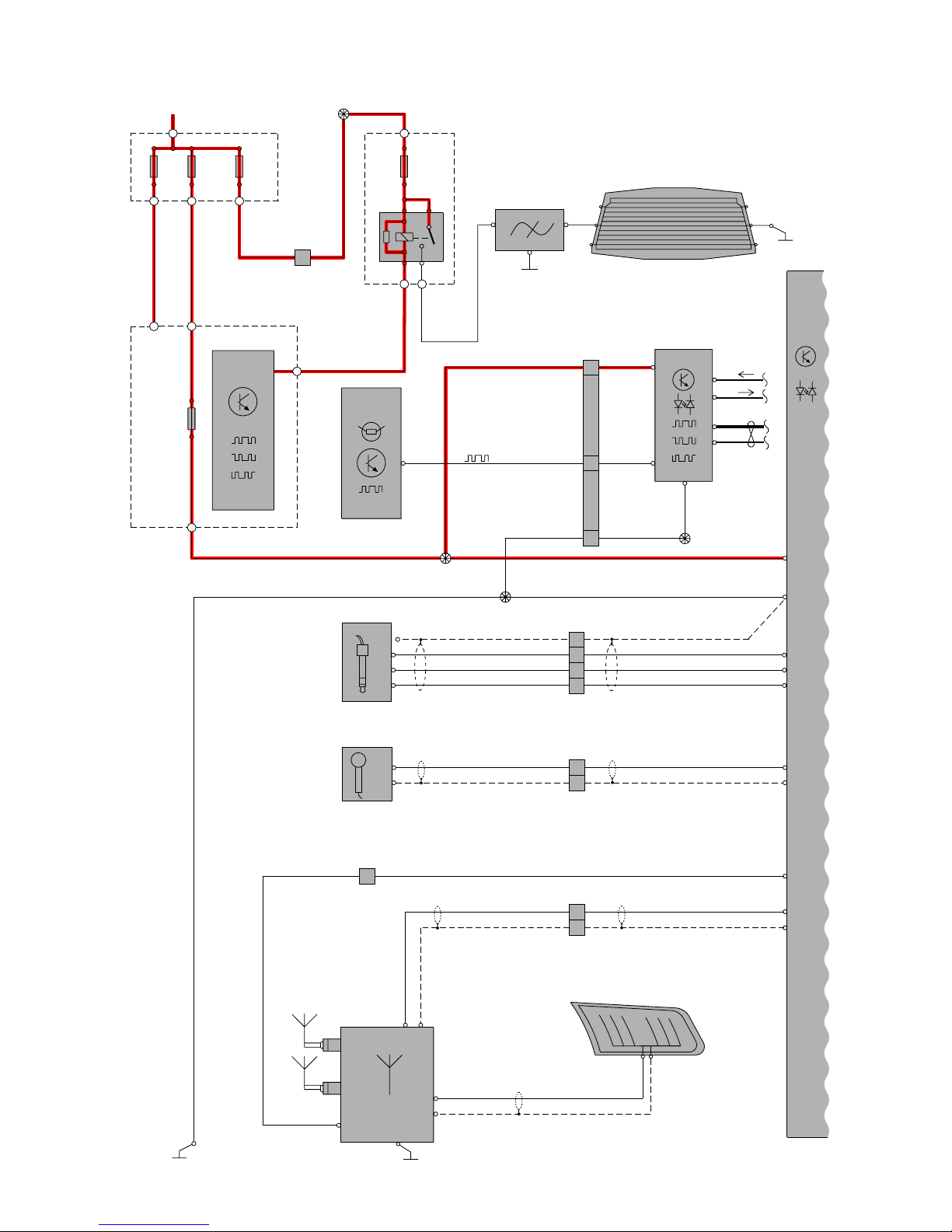
TP39127202 V70(08-), XC70(08-) & S80(07-) 2008 Supplement 90
16/1
IAM
CAN
ICM
3/281
16/98
3/130
LIN
SWM
CEM
2/82
RA1
16/16
AM/FM2
FM1
2
1
31/83
0
0
C2:1
C2:2
C1:2
C1:3
C1:6
C1:10
BK
BK
BK
WHWH
BK
GN-OGGN-OG
GY-YEGY-YE
GY-YE GY-YE
C1:6
C1:1
74/409
LIN
CAN
LIN
C2:1
BK
C5:1
11A/1
2
1
30+
C5:2
C2:26
C3:64
1
13
52
11A/2
2
1
11A/3
2
1
11D/A7
2
15/31
4/56
16/141
15/32
1
74/504B
74/401
74/412
73/5045
73/4016
73/4018
RD-GN
RD-GN
RD-GN
RD-BK
RD-BU
GY-RD
YE-RD
1
F6
2
73/5075
2
1
2
C2:8
C2:4
C2:5
21
6
22
1
8
74/405
1
1S
C2:2S / C2B:2S
C2:2 / C2B:2
C1:1
C1:2
16/123
WH
GN-VT
GN-VT
WH-BN
BN BN
WH-BN
74/403
4
2
C2:10
C2:11
1
2
1
C2:12
C3:1
C3:1S
C3:1
C1:1 C2:1
C3:1S
3
C2:2
13
9/2
WH
WHWH
WH
16/138
V70
S80
4
Group 39 Other
Audio 1:2
Page 91

TP39127202 V70(08-), XC70(08-) & S80(07-) 2008 Supplement 91
16/1
IAM
VT-BK
YE-BK
VT-BK
YE-BK
VT-BK
YE-BK
VT-BK
YE-BK
16/3.2
2
2
1
1
16/56
C1:6
C1:12
RR+
RR-
RF+
RF-
LR+
LR-
LF+
LF-
74/508
22
23
GN-BK
GY-BK
GN-BK
GY-BK
GN-BK
GY-BK
GN-BK
GY-BK
16/4.2
2
2
1
1
16/55
74/507
74/407
22
23
C1:1
C1:7
9
1
11
3
C1:4
C1:10
VT-RD
YE-RD
VT-RD
YE-RD
VT-RD
YE-RD
16/5
2
1
74/510
3
4
13
5
C1:3
C1:9
GN-RD
GY-RD
GN-RD
GY-RD
GN-RD
GY-RD
16/6
2
1
74/509
3
4
12
4
0
0
C4:1
C4:2
Group 39 Other
Audio 2:2
Page 92

TP39127202 V70(08-), XC70(08-) & S80(07-) 2008 Supplement 92
16/1
IAM
CAN
ICM
3/281
16/98
3/130
LIN
SWM
CEM
2/82
RA1
31/83
0
0
C2:1
C2:2
C1:2
C1:3
C1:6
C1:10
BK
BK
BK
WHWH
BK
GN-OG
GN-OG
GY-YE
GY-YE
GY-YE
GY-YE
GY-YEGY-YE
C1:6
C1:1
LIN
CAN
LIN
C2:1
BK
C5:1
11A/1
2
1
30+
C5:2
C2:26
1
13
52
11A/2
2
1
11A/3
2
1
11A /5
2
1
11D/A7
2
15/31
4/56
16/141
9/2
15/32
1
74/504B
74/401
74/503
74/403
74/412
73/5045
73/4016
73/4018
RD-GN
RD-GN
RD-BN
RD-BN
RD-GN
BU-RD
BU-RD
RD-BK
RD-BU
GY-RD
YE-RD
1
11D/D6
2
73/5075
73/5069
74/505
2
1
2
C2:8
C2:4
C2:5
21
6
22
1
8
C4:1
C4:2
1
22
19
O
O
54
RD1
S80
16/16
AM/FM2
FM1
2
1
74/409
74/405
1
1S
C2:2S / C2B:2S
C2:2 / C2B:2
C1:1
C1:2
WH
GN-VT
GN-VT
C3:1
C3:1S
C3:1
C1:1 C2:1
C3:1S
C2:2
13
WH
WH
16/138
V70
16/123
WH-BN
BN BN
WH-BN
74/403
4
2
C2:10
C2:11
1
2
1
C2:12
3
WHWH
4
Group 39 Other
Audio Premium 1:3
Page 93

TP39127202 V70(08-), XC70(08-) & S80(07-) 2008 Supplement 93
16/105
AUD
CEM
31/INFOT 31/631/15
CAN
LIN
C3:1
30+
C3:22
13
14
1
11A/5
2
15/31
4/56
16/111
15/32
73/5026
73/5088
73/503573/5023
BU-RD
BU-RD
BU-RD
BU-RD
BK
BK-VTBK-VT
BK-VT
BK-VTBK-GN
BK-GN
RHD
V70
LHD
BU-RD
WH-OG
BK-GN
BK
1
11D/D6
2
1
11D/D5
74/503
74/403
74/502
2
73/5069
74/505
C2:16
1
11D/D3
2
1
17
2
WH
C2:15
2
GN-VT
C2:17
3
BU-OG
C2:1
5
GY-BN
C2:13
6
YE-GN
C2:2
7
BU
C2:3
8
YE-VT
C2:14
YE
WH-OG
WH
GN-VT
BU-OG
GY-BN
YE-GN
BU
YE-VT
YE
C2:4
1
2
3
5
6
7
9
10
11
C3:2
10
BK
BU-RD
RD-BN
RD-BN
54
RD1
9
GY-RD
C1:1
C1:2
16/79
SUB
O
O
C2:1
C2:2
Group 39 Other
Audio Premium 2:3
Page 94

TP39127202 V70(08-), XC70(08-) & S80(07-) 2008 Supplement 94
16/105
AUD
VT-BK
YE-BK
VT-BK
YE-BK
VT-BK
YE-BK
VT-BK
YE-BK
16/3.2
2
2
1
1
16/56
C1:9
C1:1
RR-
RR+
RF-
RF+
LR-
LR+
LF-
LF+
74/508
73/5076
73/5077
22
23
GN-BK
GY-BK
GN-BK
GY-BK
GN-BK
GY-BK
GN-BK
GY-BK
GN-BK
GY-BK
VT-BK
YE-BK
2
1
16/3.1
2
1
16/4.1
16/4.2
2
2
1
1
16/55
74/507
73/5078
73/5079
22
23
C1:13
C1:5
VT-RD
YE-RD
VT-RD
YE-RD
16/5
2
1
74/510
3
4
VT-RD
YE-RD
16/137
2
1
C1:12
C1:4
GN-RD
GY-RD
GN-RD
GY-RD
16/6
2
1
74/509
3
4
0
0
C4:1
C4:2
C1:11
C1:3
GN-RD
GY-RD
16/136
2
1
CS-
CS+
C1:10
C1:2
GN
GY
GN
GY
VT-BK
YE-BK
GN-BK
GY-BK
VT-RD
YE-RD
GN-RD
GY-RD
GN
GY
16/26
2
1
74/409
9
10
74/407
11
3
9
1
13
5
12
4
10
2
74/407B
11
3
9
1
13
5
12
4
10
2
Group 39 Other
Audio Premium 3:3
Page 95
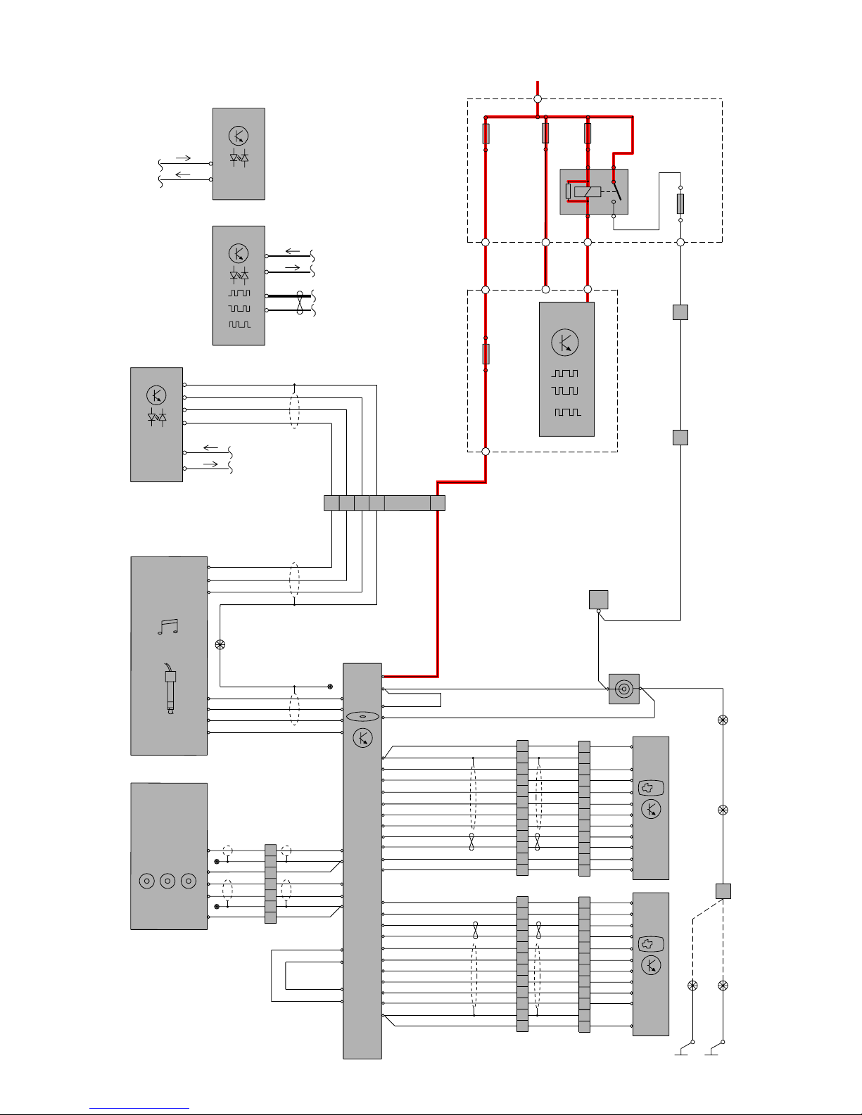
TP39127202 V70(08-), XC70(08-) & S80(07-) 2008 Supplement 95
74/502
74/504
74/403
73/5575
74/702
74/701
16/123.3
AV-IN
16/109
BU
RD
BK
BN
RD-WH
RD-VT RD-VT RD-VT
RD-BU
RD-BK
GY-YE
VT-GN
4
5
12
2
3
11
10
9
8
7
6
1
4
5
12
2
3
11
10
9
8
7
6
1
74/16123
WH
BN
GN
YE
GY
PK
7
6
5
AUX
16/123.2
2314 21
1
BK
WH
RD
BK
GN
RD-WH
7
8
9
1
6
10
11
12
5
4
3
2
7
8
9
1
6
10
11
12
5
4
3
2
BU
BN
BN
YE
GY
PK
BK
BU
RD
BN
RD-WH
WH
BN
BU-RD
BN
BU
GY-OG
WH
VT-OG
WH
GN
YE
GY
PK
WH
RD
GN
RD-WH
BU
BN
BN
YE
GY
PK
E:12
5
4
3
2
1
D:19
D:18
D:4
D:21
D:7
E:13
E:14
E:15
E:16
E:17
E:18
E:20
E:19
E:22
E:23
E:24
E:10
E:11
E:7
E:8
E:6
E:5
E:4
E:3
E:2
E:1
D:23
D:9
D:10
D:24
WH-BN
WH-BN
WH-BN
WH
WH
BN
BN
RD-WH
BN
WH
2
3
4
1
D:3
D:2
D:17
D:16
RD-VT
BK-VT
GY-YE
A:4
A:7
A:6
A:8
DVD
Y
RCA RCA RCA
W R
11A/2
30+
1
2
11A/1
15/31
1
2
11B/25
1
2
11B /27
52
3
1
R9
2/193
IAM
16/1
C2:11
C2:12
C2:10
C2:8
C5:2
C3:64
C5:1 C1:48
CAN
CEM
LIN
4/56
F6
1
2
1
2
O
O
AUD
16/105
C4:1
C4:2
O
O
BU-RD
BN
BU
WH
WH
16
CAN
ICM
3/281
C2:1
C2:2
O
O
C4:1
C4:2
C1:2
C1:3
LIN
16/81A
74/276
74/277
TFT
SB 1
R2
GN 4
YE 3
W5
GR 11
OR 10
BN 9
P8
VO 7
VO 7
P8
BN 9
OR 10
GR 11
W5
YE 3
GN 4
R2
SB 1
BL 6
BL 6
16/81B
TFT
2
3
4
1
7
6
5
73/5023
73/5035
73/5026
73/5027
74/502
BK-GN BK-GN
RHD
BK-VT
BK-VT
BK-VT BK-VT
BK-VT
LHD
2
2
9/25
9/1
RD-VT
2
1
31/15 31/6
RD-VT
Group 39 Other
Rear seat entertainment
Page 96
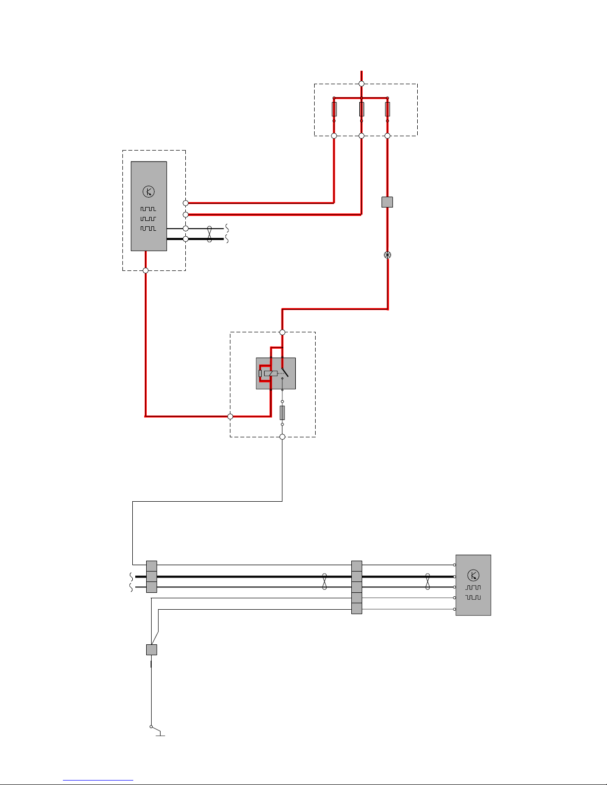
TP39127202 V70(08-), XC70(08-) & S80(07-) 2008 Supplement 96
11A/2
2
1
30+
15/31
1
2
11D/B6
C2:45
BU
C5:1
C5:2
C3:48
C3:47
4/56
CAN
LIN
CEM
11A/4
2
1
11A/1
2
1
RD-GY RD-GY
RD-GY
RD-BU
RD-BK
1
2
3
5
2/88
15/32
RB1
1
74/504B
73/5040
GN-RDGN-RD
GN-RD
BU-BK
GN-BK
BK
BK-YE
CAN
4/82
DEM
C1:8
C1:1
BK-YE
BK-YE
GN-BK
BU-BK
BK
C1:2
C1:7
C1:4
74/520
74/511
31/65
4
5
1
6
2
4
3
1
4
74/514
Group 43 Transmission
Differential Electronic Module (DEM)
Page 97

TP39127202 V70(08-), XC70(08-) & S80(07-) 2008 Supplement 97
1
2
11A/4
30+
RD-BN
RD-WH
15/31
4/56
31/47
2
C5:1
C2:5
C3:47
C3:48
C3:22
1
11A/1
RD-BK
RD-BU
CEM
CAN
LIN
74/409
73/4016
74/514
73/5070
73/4017
4/115
6/146
3/272
BU-WH
GN-VT
WH-BN
VT-GN
VT-BK
BU-GN
BU-GN
WH-OG
BN
PBM
CAN
RD-GYRD-GY
RD-GY
RD-GY
1
2
C1:15
C1:13
11D/B12
15/32
2
11D/B11
1
1
74/504B
73/5040
C1:20 3
C1:29
C1:16
C1:17
C1:14
2- 1+
87465
1
2
2
1 2
3 4 5 6 7
C1:11
C1:18
C1:9
C1:19
C1:10
C1:28
BU-WH
BU-RD
GN-VT
WH-BN
VT-GN
WH-OG
BN
BK
BK
BK-OG
BK-OG
BK-OG
C1:30
M
6/147
YE-GY
GN-BN
YE-GY
GN-BN
C1:27
C1:12
2- 1+
M
P
2 1
74/524
BK
RHD
LHD
VT-BK
BK
31/83
2
1
11A/2
Group 55 Parking brake
Electronic parking brake
Page 98
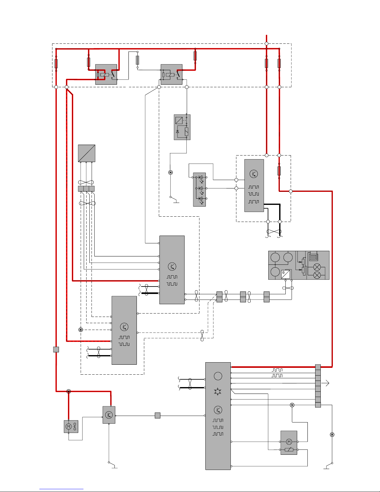
TP39127202 V70(08-), XC70(08-) & S80(07-) 2008 Supplement 98
B:B4
B:A4
6/28
ECM
4/46
C1:10
C1:8
C1:2
30+
11A/2
2
1
1
2
11A/1
4/31
ECC
4/6
C°/F°
+
-
2
1
2
3
BK
VT-BKVT-BK
C1:7
CEM
4/56
CAN
CAN
CAN
LIN
7/8
P
P
4 CYL
C1:1
C1:2
WH-GN
y
M
x
M M
F
6/62
MEM
X
MEM
Y
1
7
18
1
2
7/12
BN-BU
1
5
7
4
1
2
3
5
22
73/4028
74/401
C1:12
C1:5
C1:13
C1:14
C1:16
BN-VT
VT-BN
YE-VT
YE-VT
BK
73/4018
73/4016
BK
7/10
31/83
C1:4
C1:6
BU-WH
GN-BU
4
3
2
5
BK
BK
BK
C5:1
C3:73
C5:2
C1:50 C1:49
C3:1
C3:2
GY-YE
BK-WH
WH
BK-WH
WH
74/50774/504
74/301
7/69
31/10
1
14 13 15
132
BN
GN-BN
GY-BN
B:B2
C:C4
B:F1
C:E1
B:G1
ECM
4/46
CAN
I4
DW10
A:F2
C:B1
C:B3
C:B2
A:C1
GY-BK
GY-BN
GN-BN
BN
GY-VT
GY-BN
GN-BN
BN
GY-VT
11B/11
2
1
5(87)
3(30)
1(86)
2(85)
2/32
R10
5(87)
3(30)
1(86)
2(85)
2/22
R13
1
2
11B/33
1
2
11B/30
VT-WH
VT-WH
11B/32
1
2
1
74/411
15/31
8/3
A
LIN
6
7
BK-WH
WH
BK-WH
WH
BK-WH
WH
B:J4
B:H2
1
2
F26
YE-RDYE-RD
YE-RD
YE-RD
74/401
RD-BU
RD-BK
4
CCM
WH-GN
C1:1
RD
RD
BK-WH
8
74/301
B:H2
2
3
4 CYLD
73/3084
73/3012
31/XX5
BK-YE
BK-YE
GY-BN
A:A3
A:A4
Group 87 Climate control system
Climate control system 4 Cyl. 1:2
Page 99

TP39127202 V70(08-), XC70(08-) & S80(07-) 2008 Supplement 99
31/10
30+
BK-WH
VT-GN
15/31
1
2
11B/26
1
11B/27
74/401
74/411
C1:48
4/56
CEM
CAN
LIN
73/4010
73/4012
7/41
3/112
VT-BN
BU-BK
YE-VT
WH-GN
WH-GN
BN-VT BN-VT
BK-WH
BU-BK
2
1
2
1
4
3
5
AQS
2
1
1
3
LIN
LIN
6/103
7/159
3
2
ECC
DMM
2
1
LIN
6/48
3
DMM
2
1
LIN
6/95
3
DMM
2
1
LIN
6/96
3
DMM
2
1
LIN
6/102
3
DMM
7
A
52
3
1
R9
2/193
2
RD
RD
RD
RD
BU
BU
BU
GN
GN
GN
74/417
1
3
7
6
5
4
S1
S4
S2
S3
YE
YE
YE
BU
BU
BU
BU
GN
RD
PK
BN
RDRD
GN
2
Group 87 Climate control system
Climate control system 4 Cyl. 2:2
Page 100

TP39127202 V70(08-), XC70(08-) & S80(07-) 2008 Supplement 100
74/86
8-pin gray
No. Engine Engine
1 4/46A:34 Engine Control Module (ECM)
YE-RD
7/172:3 Intake camshaft position sen-
sor, bank 2, 8 Cyl.
YE-RD
2 73/3061 Branching point
VT
7/172:2 Intake camshaft position sen-
sor, bank 2, 8 Cyl.
VT
3 4/46A:71 Engine Control Module (ECM)
BU-BN
7/156:4 Pressure and temperature sen-
sor, fuel
BU-BN
4 73/3060 Branching point
GY
7/156:3 Pressure and temperature sen-
sor, fuel
GY
5 73/3059 Branching point
GN-BN
7/172:1 Intake camshaft position sen-
sor, bank 2, 8 Cyl.
GN-BN
6-
-
-
-
7 4/46A:46 Engine Control Module (ECM)
GY-BU
7/156:2 Pressure and temperature sen-
sor, fuel
GY-BU
8 4/46A:14 Engine Control Module (ECM)
BU-BN
7/156:1 Pressure and temperature sen-
sor, fuel
BU-BN
74/301, 4 Cyl.
34-pin black
No. Engine harness Engine compartment harness
1 4/46B:A4 Engine Control Module (ECM)
73/3014 Branching point
BU-BK
73/3021 Branching point
BU-BK
2 4/46A:A4 Engine Control Module
(ECM), diesel
73/3015 Branching point
GN-BK
73/3022 Branching point
GN-BK
3 4/46C:F3 Engine Control Module
(ECM), diesel
BN-WH
4/56C1:8 Central Electronic Module
(CEM)
BN-WH
4-
-
-
-
5-
-
-
-
6 4/46B:H2 Engine Control Module (ECM)
WH
74/504:1 Connector
WH
7 4/46B:J4 Engine Control Module
(ECM), diesel
73/3084 Branching point
BK-WH
74/504:2 Connector
BK-WH
8-
-
-
-
9 4/46B:G3 Engine Control Module (ECM)
4/46A:F4 Engine Control Module
(ECM), diesel
VT-OG
4/56C1:44 Central Electronic Module
(CEM)
VT-OG
10 4/28A:13 Transmission Control Module
(TCM)
GN-OG
74/411:9 Connector
GN-OG
11 4/28A:7 Transmission Control Module
(TCM)
BN-VT
74/411:10 Connector
BN-VT
12 4/46B:D2 Engine Control Module (ECM)
4/46C:E3 Engine Control Module
(ECM), diesel
BU-WH
74/504:17 Connector
BU-WH
continues
Connectors
74/86 - 74/301:1-12
 Loading...