

Page 1
2 0 0 5
VOLVO
V70
This manual deals with the operation and care of your Volvo.
Welcome to the worldwide family of Volvo owners. We trust that you will enjoy many years of safe driving in your
Volvo, an automobile designed with your safety and comfort in mind. To help ensure your satisfaction with this
vehicle, we encourage you to familiarize yourself with the equipment descriptions, operating instructions and
maintenance requirements/ recommendations in this manual. We also urge you and your passengers to wear seat belts
at all times in this or any other automobile. And, of course, please do not operate a vehicle if you may be affected by
alcohol, medication or any impairment that could hinder your ability to drive.
Your Volvo is designed to meet all applicable safety and emission standards, as evidenced by the certification labels
attached to the driver's door opening and on the left wheel housing in the engine compartment
For further information please contact your retailer, or:
Page 2

In the USA: In Canada:
Volvo Cars of North America Volvo Cars of Canada Ltd.
Customer Care Center National Customer Service
P.O. Box 914 175 Gordon Baker Road
Rockleigh, New Jersey 07647-0914 North York, Ontario M2H 2N7
800-458-1552 800-663-8255
http://www.volvocars.com
Contents
Contents
Chapter 1 - Safety
Chapter 2 - Instruments, switches and controls
Chapter 3 - Climate control system
Chapter 4 - Interior
Chapter 5 - Keys, Locks, Alarm
Chapter 6 - Starting and driving
Chapter 7 - Wheels and tires
Chapter 8 - Maintenance/Servicing
Chapter 9 - Specifications
Chapter 10 - Audio systems
HomeLink® Universal Transceiver (option)
Index
Back Cover
Supplement - SAFETY - AIRBAG LABELS
General information
Shiftlock
When your car is parked, the gear selector is locked in the (P)ark position. To release the selector from this position,
turn the ignition key to position II (or start the engine), depress the brake pedal, press the button on the front of the
gear selector knob and move the selector from (P)ark.
Keylock
This means that when you switch off the ignition, the gear selector must be in the (P)ark position before the key can be
Page 3

removed from the ignition switch.
Anti-lock Brake System (ABS)
The ABS system in your car performs a self-diagnostic test when the vehicle first reaches the speed of approximately
12 mph (20 km/h). The brake pedal will pulsate several times and a sound may be audible from the ABS control
module. This is normal.
Fuel filler door
Press the button on the light switch panel (see page 37) when the car is at a standstill to unlock the fuel filler door.
Please note that the fuel filler door will remain unlocked until the car begins to move forward. An audible click will be
heard when the fuel filler door relocks.
Fuel filler cap
After refueling, close the fuel filler cap by turning it clockwise until it clicks into place. If this cap is not closed tightly
or if the engine is running when the car is refueled, the Malfunction Indicator Lamp ("Check Engine" light) may
indicate a fault.
WARNING! If your vehicle is involved in an accident, unseen damage may affect your vehicle's driveability and
safety.
Important
Before you operate your car for the first time, please familiarize yourself with the new-engine oil consumption
information on page 152
manual.
. You should also be familiar with the information in chapters one, two and four of this
Information contained in the balance of the manual is extremely useful and should be read after operating the
vehicle for the first time.
The manual is structured so that it can be used for reference. For this reason, it should be kept in the car for
ready access. Do not export your Volvo to another country before investigating that country's applicable safety
and exhaust emission requirements. In some cases it may be difficult or impossible to comply with these
requirements. Modifications to the emission control system(s) may render your Volvo not certifiable for legal
operation in the U.S., Canada and other countries.
All information, illustrations and specifications contained in this manual are based on the latest product
information available at the time of publication. Please note that some vehicles may be equipped differently,
depending on special legal requirements and that optional equipment described in this manual may not be
available in all markets.
Volvo reserves the right to make model changes at any time, or to change specifications or design, without
notice and without incurring obligation.
CALIFORNIA Proposition 65 Warning
WARNING! Engine exhaust, some of its constituents, and certain vehicle components contain or emit chemicals
known to the state of California to cause cancer, and birth defects or other reproductive harm. In addition, certain
fluids contained in vehicles and certain products of component wear contain or emit chemicals known to the State of
California to cause cancer, and birth defects or other reproductive harm.
Volvo and the environment
Page 4

Volvo is committed to the well being of our customers. As a natural part of this commitment, we care about the
environment in which we all live. Caring for the environment means an everyday involvement in reducing our
environmental impact.
Volvo's environmental activities are based on a holistic view, which means we consider the overall environmental
impact of a product throughout its complete life cycle. In this context, design, production, product use, and recycling
are all important considerations. In production, Volvo has partly or completely phased out several chemicals including
freons, lead chromates, naphtanates, asbestos, mercury and cadmium; and reduced the amount of chemicals used in our
plants 50% since 1991.
In use, Volvo was the first in the world to introduce into production a three-way catalytic converter with a Lambda
sond, now called oxygen sensor, in 1976. The current version of this highly efficient system reduces emissions of
harmful substances (CO, HC, NOx) from the exhaust pipe by approximately 95% and the search to eliminate the
remaining emissions continues. Volvo is the only automobile manufacturer to offer CFC-free retrofit kits for the air
conditioning system for all models as far back as the M/Y 1975 240. Advanced electronic engine controls, refined
purification systems and cleaner fuels are bringing us closer to our goal.
After Volvo cars and parts have fulfilled their use, recycling is the next critical step in completing the life cycle. The
metal content is about 75% of the total weight of a car, which makes the car among the most recycled industrial
products. In order to have efficient and well controlled recycling, many Volvo variants have printed dismantling
manuals, indicating the weight and material of individual components. For Volvo, all homogeneous plastic parts
weighing more than 1.7 oz. (50 grams) are marked with international symbols that indicate how the component is to be
sorted for recycling.
In addition to continuous environmental refinement of conventional gasoline-powered internal combustion engines,
Volvo is actively looking at advanced technology alternative-fuel vehicles. When you drive a Volvo, you become our
partner in the work to lessen the car's impact on the environment.
To reduce your vehicle's environmental impact, you can:
Maintain proper air pressure in your tires. Tests have shown decreased fuel economy with improperly inflated tires
Follow the recommended maintenance schedule in your Warranty and Service Records Information booklet.
Drive at a constant speed
See an authorized Volvo retailer as soon as possible for inspection if the check engine (malfunction indicator) lamp
illuminates, or stays on after the vehicle has started
Properly dispose of any vehicle related waste such as used motor oil, used batteries, brake pads, etc.
When cleaning your car, use Volvo's own car care products, all of which have systematically been adapted to the
environment
PremAir®
On the surface of the radiator in the engine compartment, there is a special coating called PremAir®. PremAir® works
as a catalytic converter, converting most of the ozone passing through the radiator into oxygen, thereby reducing
harmful ground-level ozone. PremAir is a registered trademark of Engelhard Corporation.
Top of Page
Page 5

2 0 0 5
VOLVO
V70
Chapter 1 - Safety
pg. 1 Safety
Not wearing a seat belt is like believing "It'll never happen to me!" Volvo, the inventor of the three-point seat belt,
urges you and all adult occupants of your car to wear seat belts and ensure that children are properly restrained, using
an infant, car or booster seat determined by age, weight and height. Volvo also believes no child should sit in the front
seat of a car.
Fact:In every state and province, some type of child-restraint legislation has been passed. Additionally, most states
and provinces have already made it mandatory for occupants of a car to use seat belts.
So, urging you to "buckle up" is not just our recommendation - legislation in your state or province may mandate seat
belt usage. The few seconds it takes to buckle up may one day allow you to say, "It's a good thing I was wearing my
seat belt."
Seat belts
Center head restraint 3
Front airbags (SRS) 4
Occupant weight sensor 8
Side impact airbags (SIPS) 10
Volvo Inflatable Curtain (VIC) 11
Whiplash Protection System (WHIPS) 12
Child safety 13
Occupant safety 19
Brake system 20
Anti-lock Brake System (ABS) 21
Stability Traction Control (STC) 22
Dynamic Stability Traction Control (DSTC) 22
2
pg. 2 Seat belts
Seat belts
Page 6
Always fasten the seat belts before you drive or ride. A chime will sound several times if the driver's seat belt is
not fastened.
To buckle:
Pull the belt out far enough to insert the latch plate into the receptacle until a distinct click is heard. The seat belt
retractor is normally "unlocked" and you can move freely, provided that the shoulder belt is not pulled out too far. The
retractor will lock up as follows:
if the belt is pulled out rapidly
during braking and acceleration
if the vehicle is leaning excessively
when driving in turns
For the seat belt to provide maximum protection in the event of an accident, it must be worn correctly. When wearing
the seat belt remember:
The belt should not be twisted or turned.
The lap belt must be positioned low on the hips (not pressing against the abdomen).
Make sure that the shoulder belt is rolled up into its retractor and that the shoulder and lap belts are taut.
The seat belts are equipped with tensioners that reduce slack in the seat belts. These tensioners are triggered in
situations where the airbags deploy.
The front seat belts also include a tension reducing device which, in the event of a collision, limits the peak forces
exerted by the seat belt on the occupant.
Before exiting the car, check that the seat belt retracts fully after being unbuckled. If necessary, guide the belt back
into the retractor slot.
NOTE: Legislation in your state or province may mandate seat belt usage.
Adjusting shoulder belt
Lap portion of the belt should sit low
Child seats: Please refer to page 16 for information on securing child seats with the seat belts.
Page 7
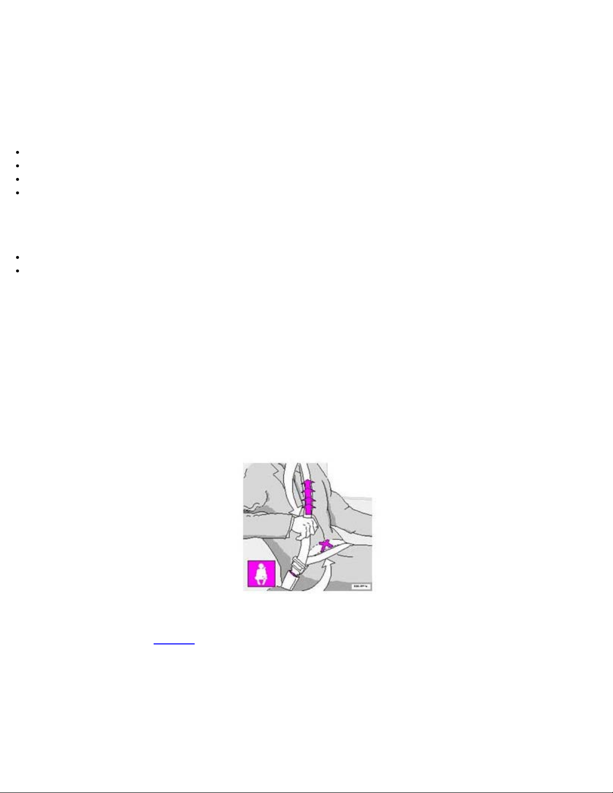
During pregnancy
to support the occupant's head.
Pregnant women should always wear seat belts. Remember that the belt should always be positioned in such a way as
to avoid any possible pressure on the abdomen. The lap portion of the belt should be located low, as shown in the
above illustration.
pg. 3 Seat belts, Center head restraint
WARNING!
Never use a seat belt for more than one occupant.
Never wear the shoulder portion of the belt under the arm, behind the back or otherwise out of position. Such use
could cause injury in the event of an accident.
As the seat belts lose much of their strength when exposed to violent stretching, they should be replaced after any
collision, even if they appear to be undamaged.
Never repair the belt on your own; have this work done by an authorized Volvo retailer only.
Any device used to induce slack into the shoulder belt portion of the three-point belt system will have a
detrimental effect on the amount of protection available to you in the event of a collision.
The seat back should not be tilted too far back. The shoulder belt must be taut in order to function properly.
Do not use child safety seats or child booster cushions/backrests in the front passenger's seat. We also recommend
that children who have outgrown these devices sit in the rear seat with the seat belt properly fastened.
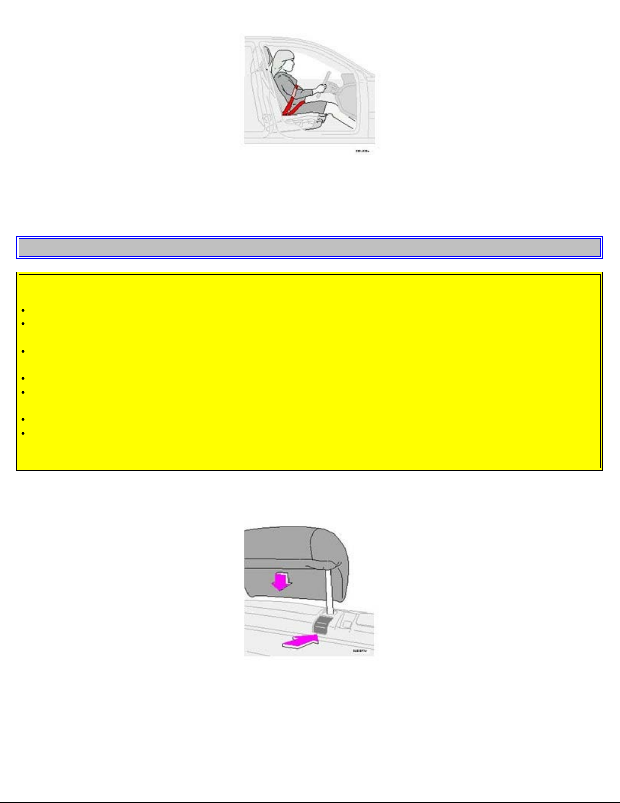
Adjust head restraint height
Center head restraint (rear)
The center head restraint can be adjusted according to the passenger's height. The restraint should be carefully adjusted
Page 8
To raise, lift up to desired position. To lower the center head restraint, press the release button behind the right-hand
support while pressing down the head restraint to the desired position.
WARNING!
Please note that the lowest head restraint position is only intended for use when the backrest is to be folded down,
or when the seat is not occupied.
The head restraint is intended to help protect the head/neck in a collision. Ensure that it is properly adjusted for
the occupant of the seat.
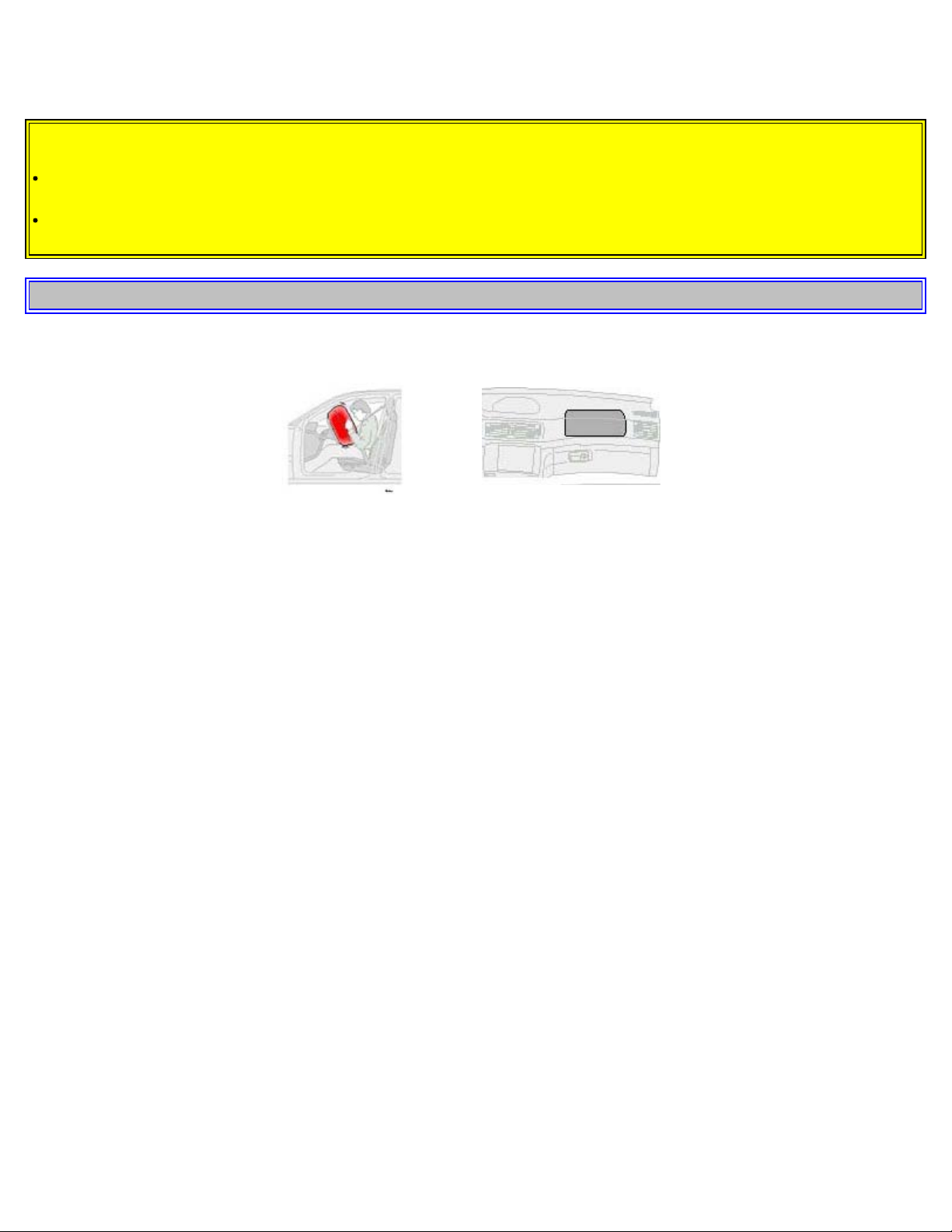
pg. 4 Front airbags - SRS
Driver's side airbag - in
steering wheel hub
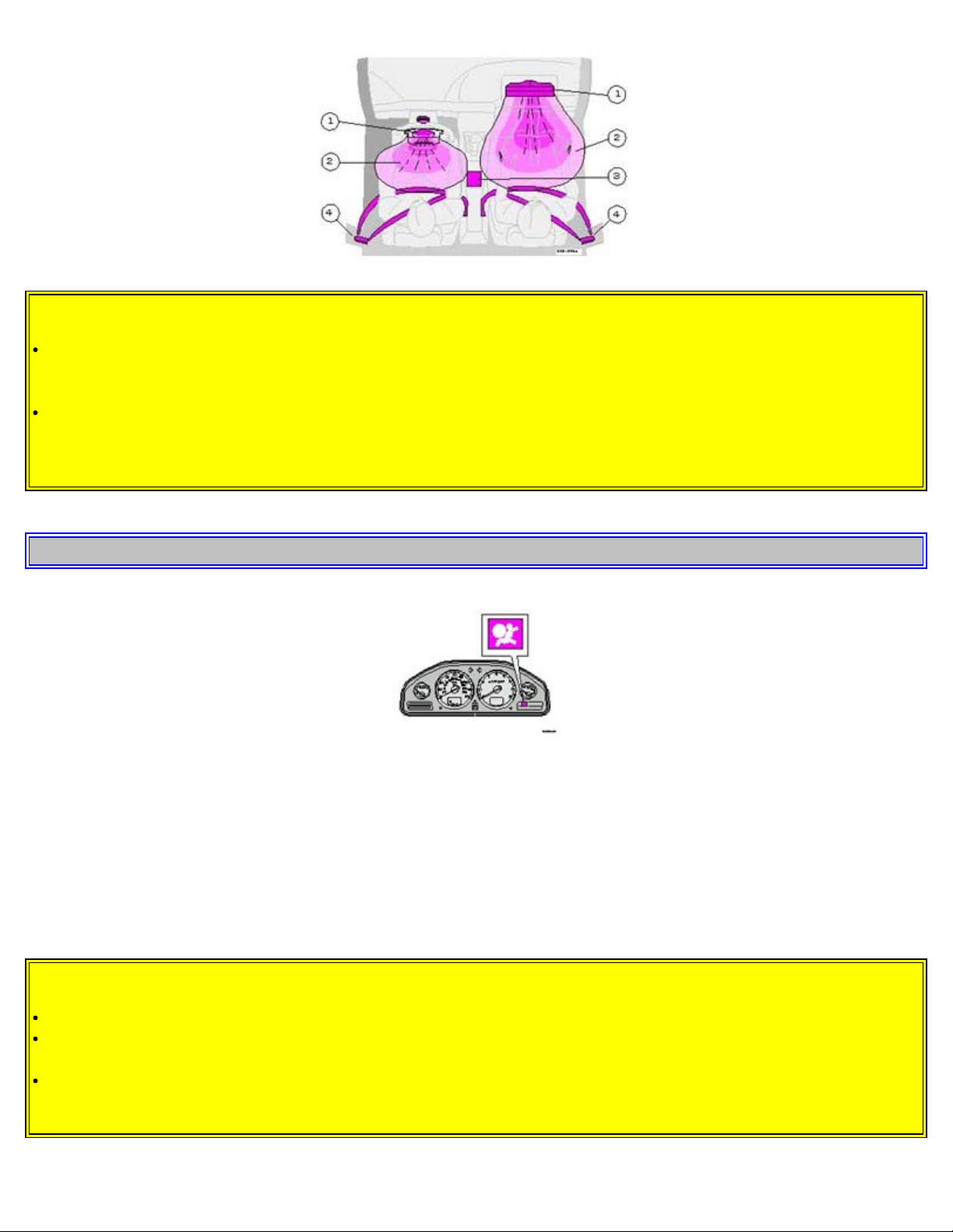
As an enhancement to the three-point seat belt system, your Volvo is equipped with a Supplemental Restraint System
(SRS). The Volvo SRS consists of an airbag (2) on both the driver's and passenger's sides and seat belt tensioners in
both front door pillars (4). The system is designed to supplement the protection provided by the three-point seat belt
system. All three rear seat belts are also equipped with tensioners.
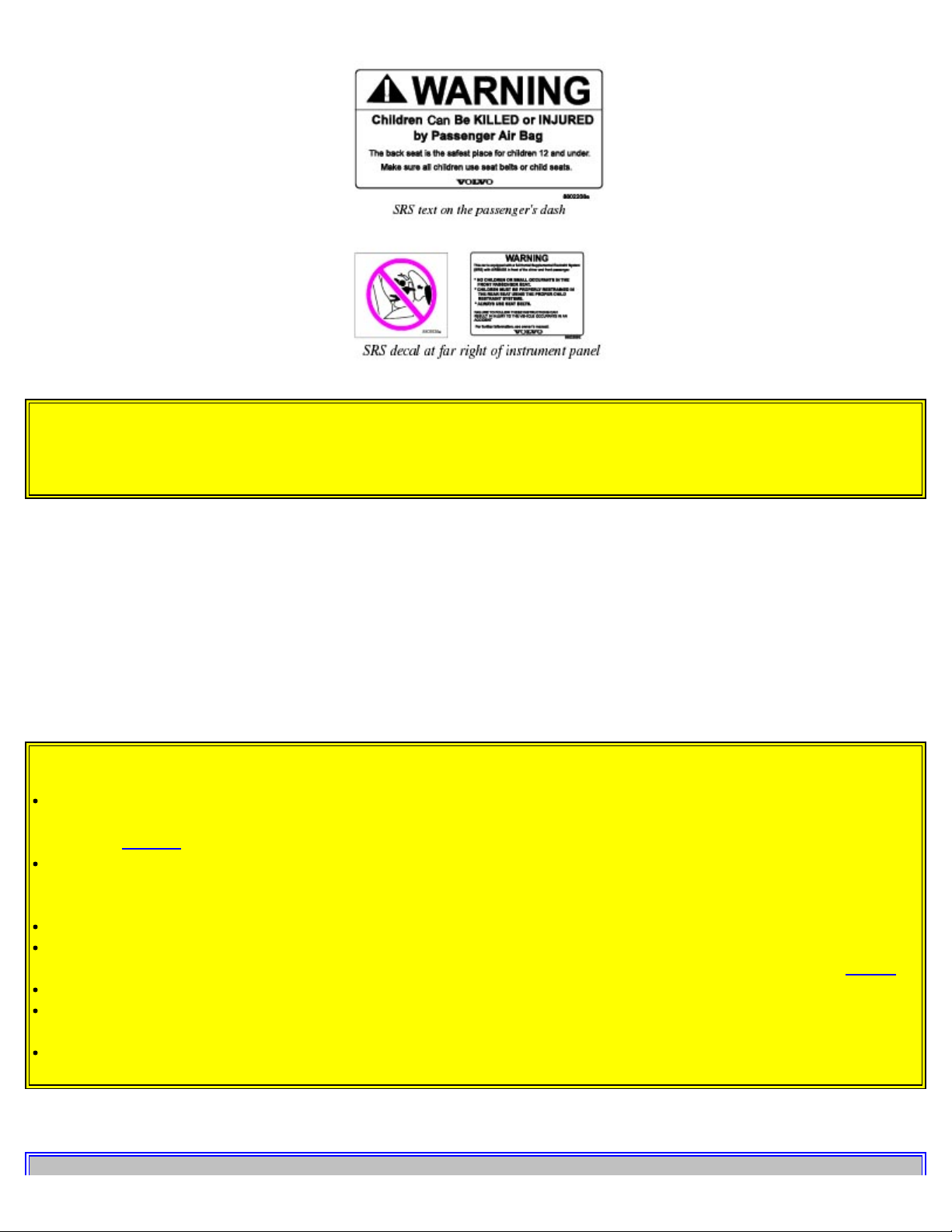
The SRS system is indicated by the "SRS" embossed on the steering wheel pad and above the glove compartment, and
by decals on both sun visors and on the front and far right side of the dash.
The airbags are folded and located in the steering wheel hub and above the glove compartment. They are designed to
deploy during certain frontal or front-angular collisions, impacts, or decelerations, depending on the crash severity,
angle, speed and object impacted. The airbags may also deploy in certain non-frontal collisions where rapid
deceleration occurs.
The airbag system includes gas generators (1) surrounded by the airbags (2) and front seat belt tensioners for both of
the front seats (4). To deploy the system, the sensor (3) activates the gas generators causing the airbags to be inflated
with nitrogen gas. As the movement of the seats' occupants compresses the airbags, some of the gas is expelled at a
controlled rate to provide better cushioning. Both seat belt tensioners also deploy, minimizing any seat belt slack.
The entire process, including inflation and deflation of the airbags, takes approximately two-tenths of a second.
Passenger's side airbag - above
glove compartment
Page 9
WARNING!
As its name implies, SRS is designed to be a SUPPLEMENT to -not a replacement for - the three-point belt
system. For maximum protection, wear seat belts at all times. Be aware that no system can prevent all possible
injuries that may occur in an accident.
When installing any optional equipment, make sure that the SRS system is not damaged. Do not attempt to service
any component of the SRS yourself. Attempting to do so may result in serious personal injury. If a problem arises,
take your car to the nearest authorized Volvo retailer for inspection as soon as possible.
pg. 5 Front airbags - SRS
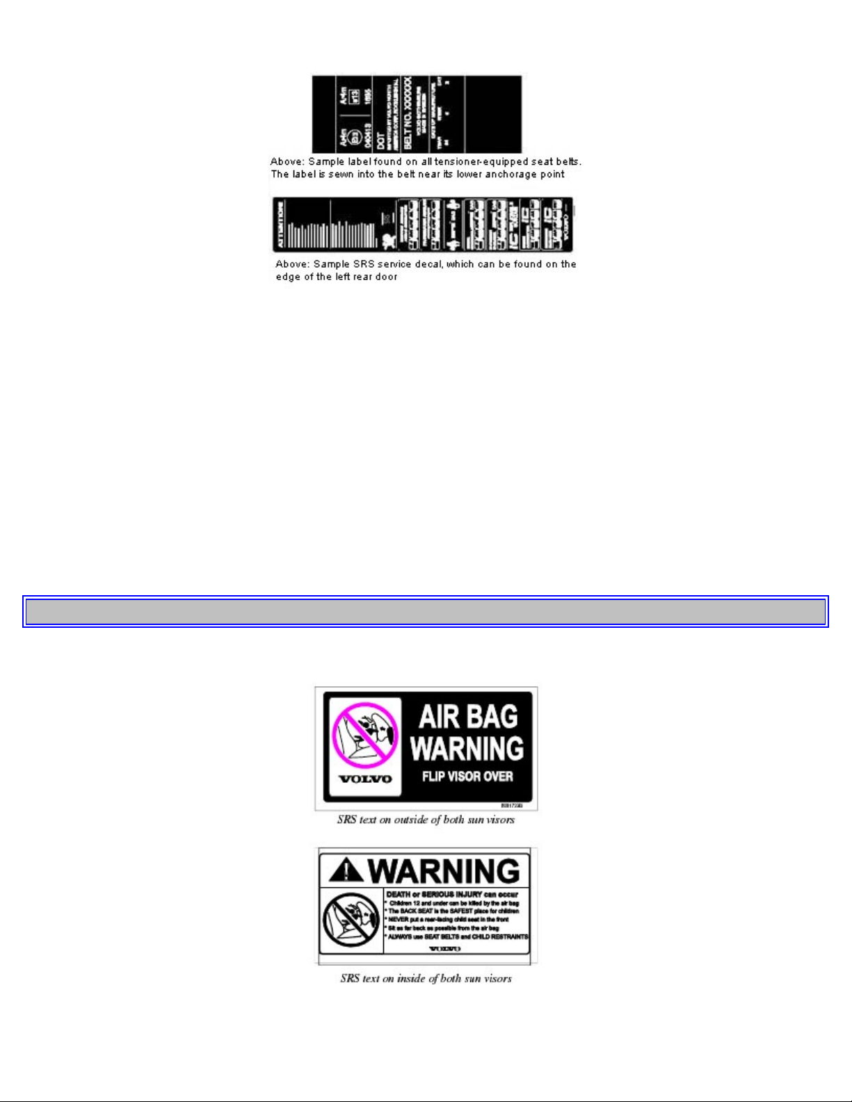
Safety system warning light in the instrument panel
A self-diagnostic system incorporated in the sensor monitors certain safety system components. A check is performed
on components such as seat belt locks, SRS, SIPS, the front passenger's seat occupant weight sensor, and/or the VIC
system. If a fault is detected, the warning light will illuminate. The light is included in the warning/indicator light
cluster in the instrument panel. Normally, the safety system warning lamp should light up when the ignition key is
turned to positions I, II or III and should go out after approximately 7 seconds or when the engine is started. Check that
this light is functioning properly every time the vehicle is started.
WARNING!
Never drive an SRS equipped car with your hands on the steering wheel pad / airbag housing.
No objects, accessory equipment or stickers may be placed on, attached to or installed near the SRS cover in the
center of the steering wheel, the SRS cover above the glove compartment or the area affected by airbag deployment.
If the SRS warning light stays on after the engine has started or if it comes on while you are driving, drive the car
to the nearest authorized Volvo retailer for inspection as soon as possible.
Page 10
There is no maintenance to perform on the SRS yourself. The month and year shown on the decal on the door pillar
indicate when you should contact your Volvo retailer for specific servicing or replacement of airbags and seat belt
tensioners. This service must be performed by an authorized Volvo retailer.
Should you have any questions about the SRS system, please contact your authorized Volvo retailer or Volvo
Customer Support:
In the USA: In Canada:
Volvo Cars of North America Volvo Cars of Canada Ltd.
Customer Care Center National Customer Service
P.O. Box 914 175 Gordon Baker Road
Rockleigh, New Jersey 07647-0914 North York, Ontario M2H 2N7
800-458-1552 800-663-8255
pg. 6 Front airbags - SRS
Page 11
WARNING!
Do not use child safety seats or child booster cushions/backrests in the front passenger's seat. We also recommend
that occupants under 4 feet 7 inches (140 cm) in height who have outgrown these devices sit in the rear seat with the
seat belt fastened.
NOTE: Deployment of SRS components occurs only one time during an accident. In a collision where deployment
occurs, the airbags and seat belt tensioners activate. Some noise occurs and a small amount of powder is released. The
release of the powder may appear as smoke-like matter. This is a normal characteristic and does not indicate fire.
Volvo's dual-threshold, dual-stage airbags use special sensors to control deployment. The point at which the airbag
deploys is determined by whether or not the seat belt is being used, as well as the severity of the collision. Collisions
can occur where only one of the airbags deploys.
If the impact is less severe, but severe enough to present a clear injury risk, the dual-stage airbags are triggered at 7080% of their total capacity. If the impact is more severe, the dual-stage airbags are triggered at full capacity.
WARNING!
Children must never be allowed in the front passenger seat. Volvo recommends that ALL occupants (adults and
children) shorter than 4 feet 7 inches (140 cm) be seated in the back seat of any vehicle with a passenger-side front
airbag. See page 16 for guidelines.
Occupants in the front passenger's seat must never sit on the edge of the seat, sit leaning toward the instrument
panel or otherwise sit out of position. The occupant's back must be as upright as comfort allows and be against the
seat back with the seat belt properly fastened.
Feet must be on the floor, e.g. not on the dash, seat or out of the window.
No objects or accessory equipment, e.g. dash covers, may be placed on, attached to or installed near the SRS
hatch (the area above the glove compartment) or the area affected by airbag deployment (see illustration on page 4 ).
There should be no loose articles, e.g. coffee cups, on the floor, seat or dash area.
Never try to open the SRS cover on the steering wheel or the passenger side dash. This should only be done by an
authorized Volvo service technician.
Failure to follow these instructions can result in injury to the vehicle occupants.
Page 12

pg. 7 Front airbags - SRS
NOTE: The information on this page does not pertain to the Side Impact Protection System airbags.
systems can also be damaged. The smoke and dust formed when the airbags are deployed can cause skin and eye
When are the airbags deployed?
The SRS system is designed to deploy during certain frontal or front-angular collisions, impacts, or decelerations,
depending on the crash severity, angle, speed and object impacted. The SRS sensor is designed to react to both the
impact of the collision and the inertial forces generated by it and to determine if the intensity of the collision is
sufficient for the airbags to be deployed.
WARNING!
The SRS is designed to help prevent serious injury. Deployment occurs very quickly and with considerable force.
During normal deployment and depending on variables such as seating position, one may experience abrasions,
bruises, swellings, or other injuries as a result of airbag(s) deployment.
If the airbags have been deployed, we recommend the following:
Have the car towed to an authorized Volvo retailer. Never drive with the airbags deployed.
Have an authorized Volvo retailer replace the SRS system components.
Use only new, Genuine Volvo Parts when replacing SRS components (airbags, seat belts, tensioners, etc.).
When are the airbags NOT deployed?
Not all frontal collisions activate the SRS system. If the collision involves a nonrigid object (e.g., a snow drift or
bush), or a rigid, fixed object at a low speed, the SRS system will not necessarily deploy. Front airbags do not
normally deploy in a side impact collision, in a collision from the rear or in a rollover situation. The amount of
damage to the bodywork does not reliably indicate if the airbags should have deployed or not.
Seat belts - the heart of the Volvo safety system
The heart of the Volvo safety system is the three-point seat belt (a Volvo invention)! In order for the SRS system to
provide the protection intended, seat belts must be worn at all times by everyone in the car. The SRS system is a
supplement to the seat belts.
WARNING!
If your car has been subjected to flood conditions (e.g. soaked carpeting/standing water on the floor of the vehicle)
or if your car has become flood-damaged in any way, do not attempt to start the vehicle or put the key in the ignition
before disconnecting the battery (see below). This may cause airbag deployment which could result in personal
injury. Have the car towed to an authorized Volvo retailer for repairs.
Automatic transmission:
Before attempting to tow the car, use the following procedure to override the shiftlock system to move the gear
selector to the neutral position.
Switch off the ignition for at least 10 minutes and disconnect the battery
Wait at least one minute
Insert the key in the ignition and turn it to position II
Press firmly on the brake pedal.
Move the gear selector from (P)ark to the (N)eutral position.
WARNING!
Never drive with the airbags deployed. The fact that they hang out can impair the steering of your car. Other safety
Page 13
irritation in the event of prolonged exposure.
pg. 8 Occupant Weight Sensor (OWS)*
Disabling the passenger's side front airbag
Volvo recommends ALL occupants (adults and children) shorter than four feet seven inches (140 cm) be seated in the
back of any vehicle with a front passenger side airbag, and be properly restrained for their size and weight. See also
the child safety recommendations on page 16.
The passenger's side front airbag is automatically enabled/disabled by the Occupant Weight Sensor (OWS)*, a system
that monitors the weight of the person or object in the front passenger's seat. The system consists of a silicon-filled bag
located under the padding in the front passenger's seat cushion, a control module located under this seat, and a seat belt
tension sensor, located on the outboard side of the seat.
*NOTE: Not available on the V70R.
Page 14

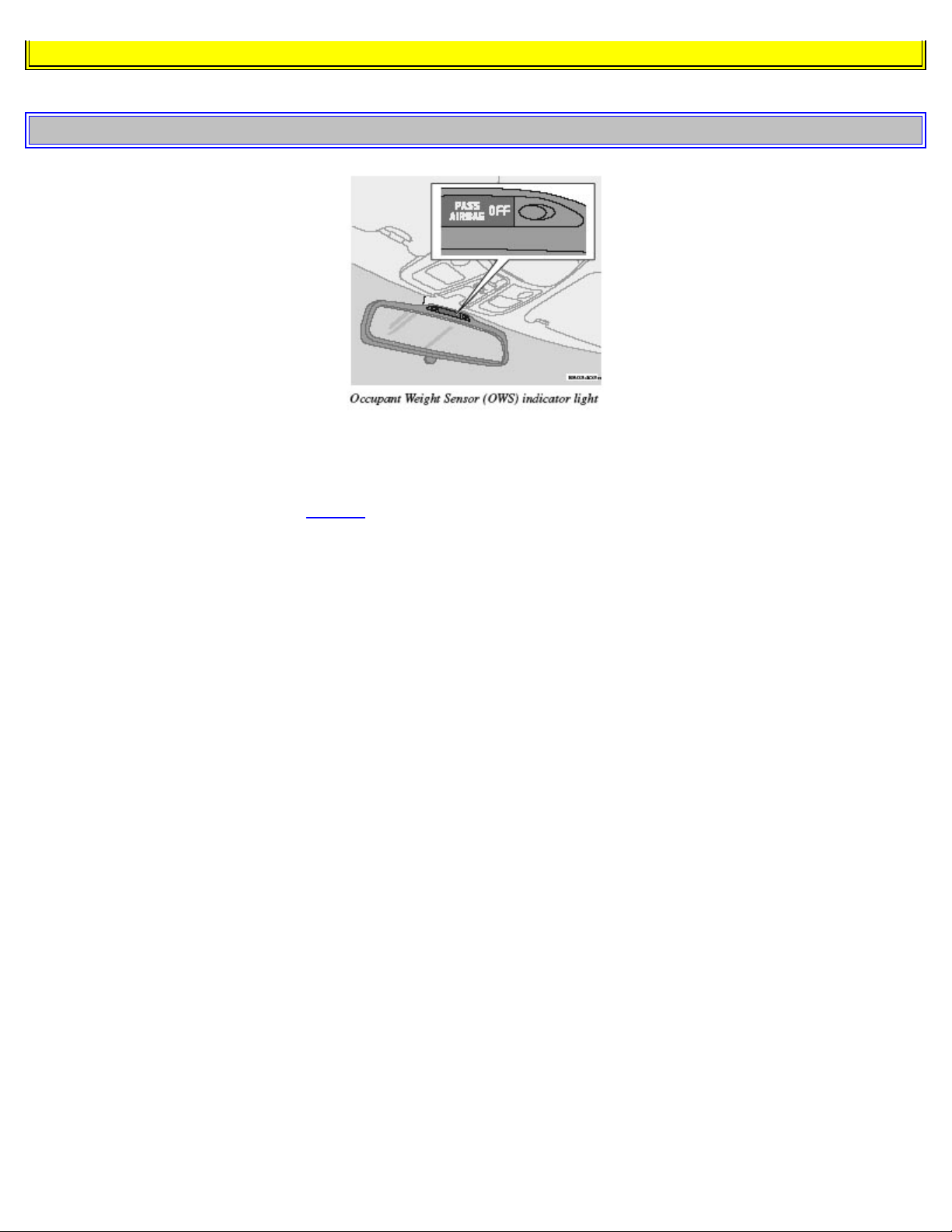
If the system is functioning normally, the status of the front passenger's side airbag (enabled/ disabled) will be shown
by the OWS indicator light as explained in the table to the left. The OWS indicator light is separate and in addition to
the SRS warning light in the instrument panel.
NOTE: When the ignition is switched on, the OWS indicator light will go on for up to 10 seconds while the system
performs a self-diagnostic test and then go out.
However, if a fault is detected in the system:
· The OWS indicator light will stay on
· The safety system warning light (see page 5) will come on and stay on
· The message PASS. AIRBAG OFF SERVICE URGENT will be displayed in the information display.
WARNING!
If a fault in the system is detected and indicated as explained above, be aware that the passenger's side front airbag
will not deploy in the event of a collision.
In this case, the safety systems and Occupant Weight Sensor should be inspected by an authorized Volvo retailer as
soon as possible.
Page 15

pg. 9 Occupant Weight Sensor (OWS)*
WARNING!
Never try to open, remove, or repair any components in the OWS system. This could result in system malfunction.
Maintenance or repairs should only be carried out by an authorized Volvo service technician.
*NOTE: Not available on the V70R.
WARNING!
Keep the following points in mind with respect to the OWS system. Failure to follow these instructions could
adversely affect the system's function and result in serious injury to the occupant of the front passenger's seat:
The full weight of the front seat passenger should always be on the seat cushion. The passenger should never lift
him/herself off the seat cushion using the armrest in the door or the center console, by pressing the feet on the floor,
by sitting on the edge of the seat cushion, or by pressing against the backrest in a way that reduces pressure on the
seat cushion. This could cause OWS to disable the front, passenger's side airbag.
The front passenger's seat should not be modified in any way. This could reduce pressure on the seat cushion, which
might interfere with the OWS system's function.
Do not place any type of object on the front passenger's seat in such a way that jamming, pressing, or squeezing
occurs between the object and hte front seat, other than as a direct result of the correct use of the ALR/ELR seat belt
(see page 16)
.
No objects should be placed under the front passenger's seat. This could interfere with the OWS system's function.
WARNING!
No objects that add to the total weight on the seat should be placed on the front passenger's seat. If a child is seated
in the front passenger's seat with any additional weight, this extra weight could cause the OWS system to enable the
airbag, which might cause it to deploy in the event of a collision, thereby injuring the child.
The seat belt should never be wrapped around an object on the front passenger's seat. This could interfere with the
OWS system's function.
The front passenger's seat belt should never be used in a way that exerts more pressure on the passenger than
normal. This could increase the pressure exerted on the weight sensor by a child, and could result in the airbag being
enabled, which might cause it to deploy in the event of a collision, thereby injuring the child.
pg. 10 Side impact airbags (SIPS)
Page 16
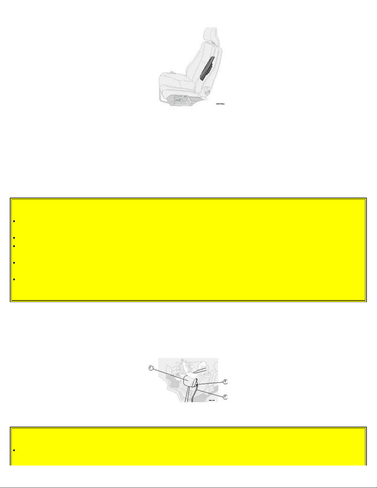
SIPS airbag *
SIPS airbag (front seats only)
As an enhancement to the structural Side Impact Protection System built into your car, the car is also equipped with
Side Impact Protection System (SIPS) airbags. The SIPS airbag system consists of airbag modules built into the sides
of both front seat backrests (1), wires (2) and gas generators/sensor units (3). The SIPS airbag system is designed to
help increase occupant protection in the event of certain side impact collisions. The SIPS airbags are designed to
deploy only during certain side-impact collisions, depending on the crash severity, angle, speed and point of impact.
The airbags are not designed to deploy in all side impact situations.
WARNING!
The SIPS airbag system is a supplement to the Side Impact Protection System and the three-point seat belt system.
It is not designed to deploy during collisions from the front or rear of the car or in rollover situations.
The use of seat covers on the front seats may impede SIPS airbag deployment.
No objects, accessory equipment or stickers may be placed on, attached to or installed near, the SIPS airbag
system or in the area affected by SIPS airbag deployment (see illustration below).
Never try to open or repair any components of the SIPS airbag system. This should be done only by an authorized
Volvo service technician.
In order for the SIPS airbag to provide its best protection, both front seat occupants should sit in an upright
position with the seat belt properly fastened.
NOTE: SIPS airbag deployment (one airbag) occurs only on the side of the vehicle affected by the impact.
*A SIPS airbag warning decal is also located at the end of the instrument panel on the driver's side of the car.
1 - Airbag, 2 - wire, 3 - gas generator/sensor unit
WARNING!
Never drive with the airbags deployed. The fact that they hang out can impair the steering of your car. Other safety
systems can also be damaged. The smoke and dust formed when the airbags are deployed can cause skin and eye
Page 17
irritation in the event of prolonged exposure.
If your car has been subjected to flood conditions (e.g. soaked carpeting/standing water on the floor of the vehicle)
service technician.
or if your car has become flood-damaged in any way, do not attempt to start the vehicle or put the key in the ignition
before disconnecting the battery. This may cause airbag deployment which could result in personal injury. Have the
car towed to an authorized Volvo retailer for repairs.
pg. 11 Volvo Inflatable Curtain (VIC)
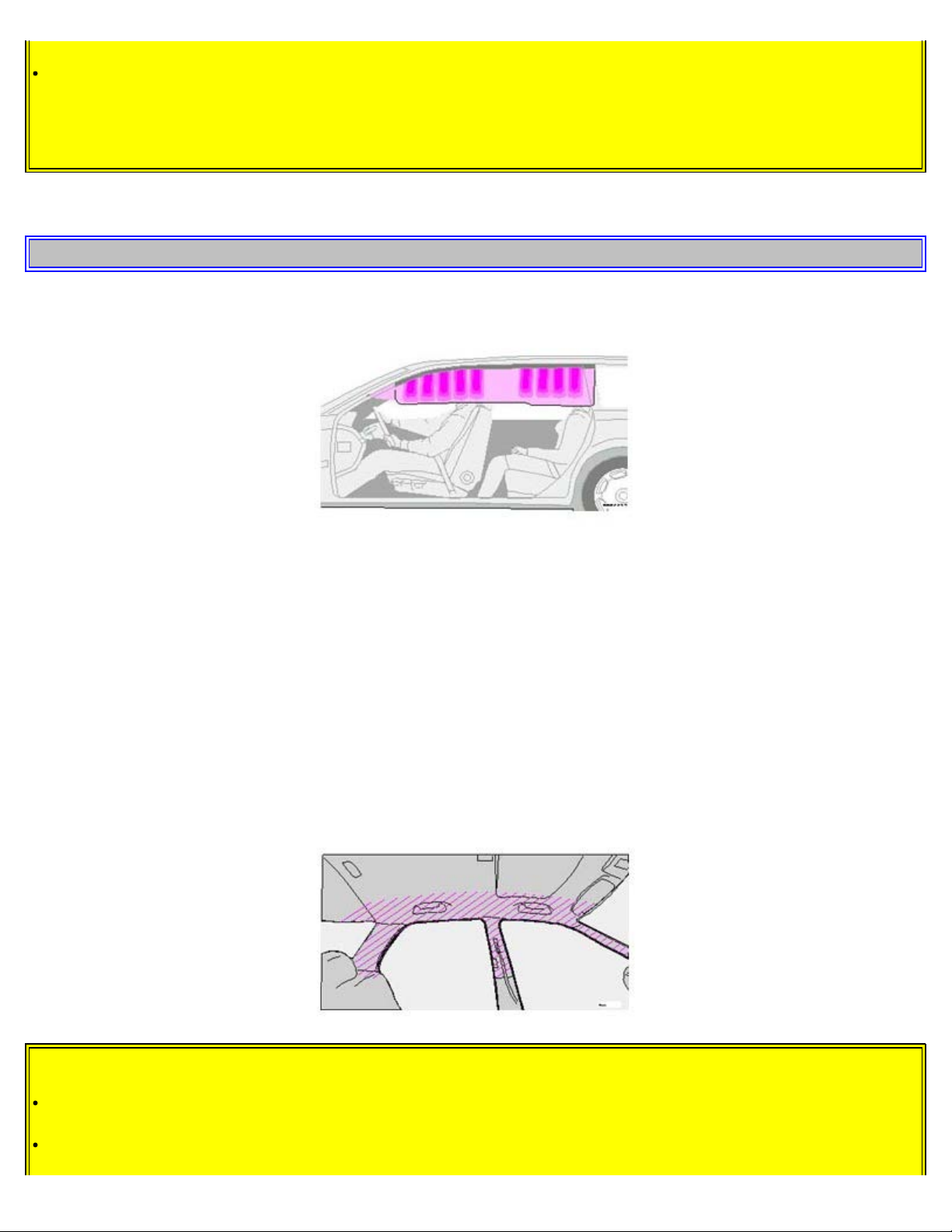
Volvo Inflatable Curtain (VIC)
This system consists of inflatable curtains located along the sides of the roof liners, stretching from the center of both
front side windows to the rear edge of the rear side door windows. It is designed to help protect the heads of the
occupant of the front seat and the occupant of the outboard rear seat position in certain side impact collisions.
NOTE: IC system deployment occurs only on the side of the vehicle affected by the impact.
In certain side impacts, BOTH the Inflatable Curtain (IC) and the Side Impact Airbag System (SIPS-bag) will deploy,
whereas, in some cases, ONLY the Inflatable Curtain (IC) will deploy. In cases where BOTH the IC and the SIPS-bag
deploy, deployment will occur simultaneously.
If the inflatable curtain deploys, it remains inflated for approximately 3 seconds.
WARNING!
The IC system is a supplement to the Side Impact Protection System. It is not designed to deploy during collisions
from the front or rear of the car or in rollover situations.
Never try to open or repair any components of the IC system. This should be done only by an authorized Volvo
Page 18
The inflatable curtains are designed to deploy only during certain side-impact collisions, depending on the crash
severity, angle, speed and impact. The inflatable curtains are not designed to deploy in all side impact situations.
In order for the IC to provide its best protection, both front seat occupants and both outboard rear seat occupants
should sit in an upright position with the seat belt properly fastened; adults using the seat belt and children using the
proper child restraint system. Only adults should sit in the front seats. Children must never be allowed in the front
passenger seat. See page 16 for guidelines. Failure to follow these instructions can result in injury to the vehicle
occupants.
When the rear seat backrest(s) are folded down, the car should not be loaded to a level higher than 2 in. (5 cm)
below the upper edge of the rear passenger door windows. Objects placed higher than this level could impede the
function of the inflatable curtain.
pg. 12 Whiplash Protection System (WHIPS)
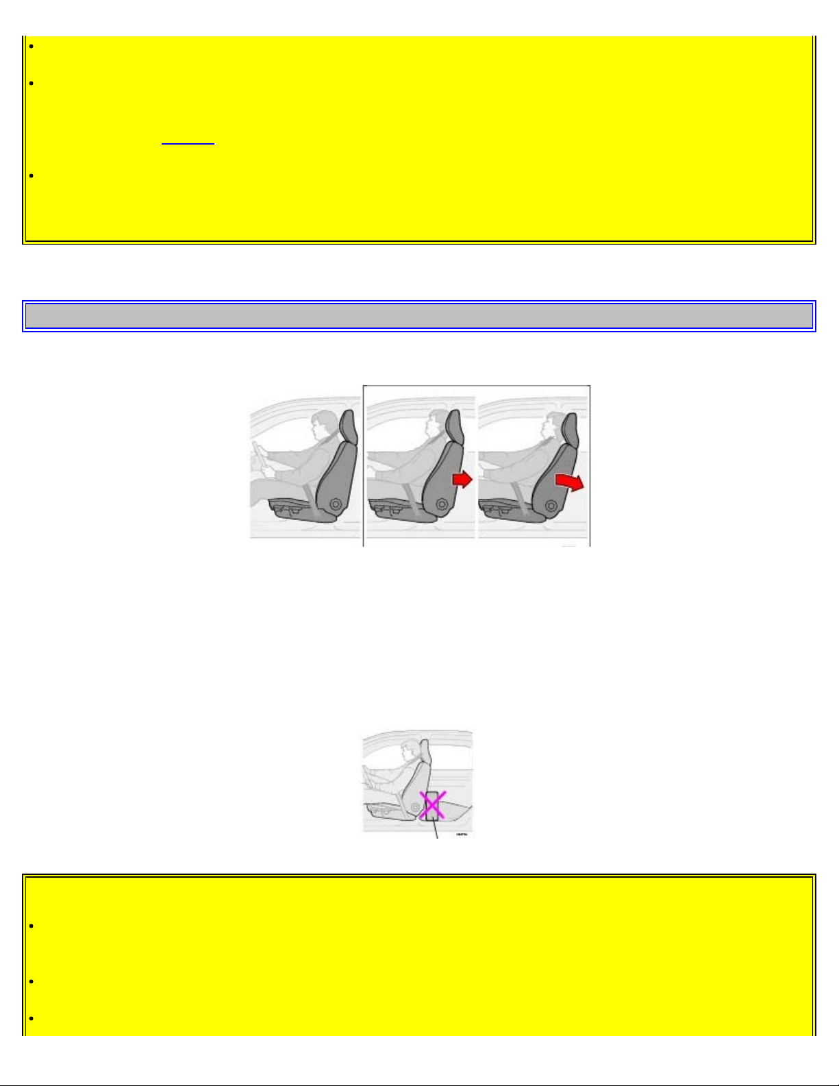
Whiplash Protection System (WHIPS) - front seats only
The WHIPS system consists of specially designed hinges and brackets on the front seat backrests and head restraints
designed to help absorb some of the energy generated in a collision from the rear ("rear-ended").
In the event of a collision of this type, the hinges and brackets of the front seat backrests are designed to change
position slightly to allow the backrest/head restraint to help support the occupant's head before moving slightly
rearward. This movement helps absorb some of the forces that could result in the whiplash effect.
Do not wedge boxes, suitcases, etc. behind front seats
WARNING!
Any contact between the front seat backrests and the folded rear seat could impede the function of the WHIPS
system. If the rear seat is folded down, the occupied front seats must be adjusted forward so that they do not touch
the folded rear seat.
Boxes, suitcases, etc. wedged behind the front seats (see illustration above) could impede the function of the
WHIPS system.
The WHIPS system is designed to supplement the other safety systems in your car. For this system to function
Page 19
properly, the three-point seat belt must be worn. Please be aware that no system can prevent all possible injuries that
may occur in an accident.
If your car has been involved in a collision, the front seat backrests must be inspected by an authorized Volvo
retailer even if the seats appear to be undamaged. Certain components in the WHIPS system may need to be
replaced. Do not attempt to service any component in the WHIPS system yourself.
If the rear seat backrests are folded down, cargo must be secured to prevent it from sliding forward against the
front seat backrests in the event of a collision from the rear. This could interfere with the action of the WHIPS
system.
The WHIPS system is designed to function in certain collisions from the rear, depending on the crash severity,
angle and speed.
Occupants in the front seats must never sit out of position. The occupant's back must be as upright as comfort
allows and be against the seat back with the seat belt properly fastened.
Contents | Top of Page
Page 20

2 0 0 5
VOLVO
V70
Chapter 2 - Instruments, switches and controls
pg. 25 Instruments, switches and controls
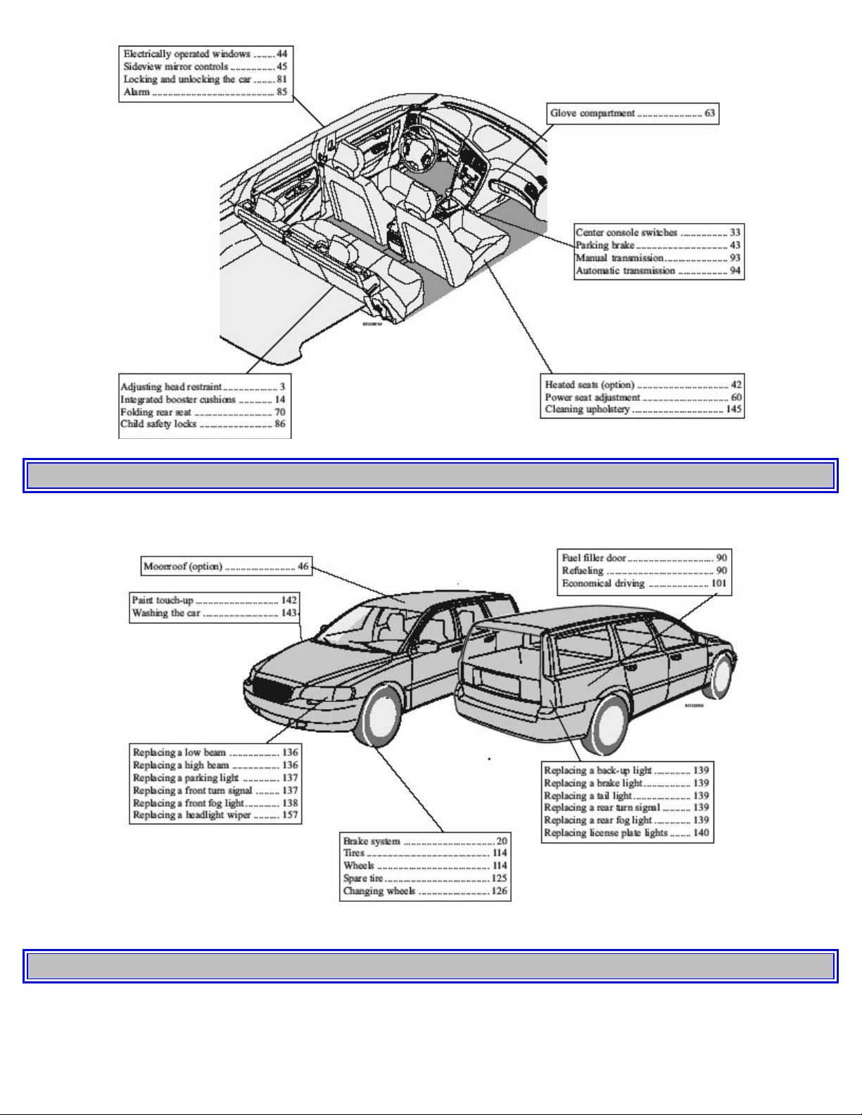
Interior 26
Exterior 27
Instruments 28
Instrument panel 29
Indicator and warning lights 30
Text information window 32
Switches in the center console 33
Trip computer 34
Cruise control 35
Light switch panel 37
Steering wheel adjustment/lock 38
Ignition switch, Turn signals 39
Windshield wipers/washers, 40
Tailgate wipers/washers, Water repellent glass 41
Warning flashers, heated mirrors/rear window, heated front seats 42
Parking brake, auxiliary socket/ashtrays 43
Electrically operated windows 44
Rearview/sideview mirrors 45
Power moonroof 46
pg. 26 Interior
Page 21
pg. 27 Exterior
pg. 28 Instruments
Page 22
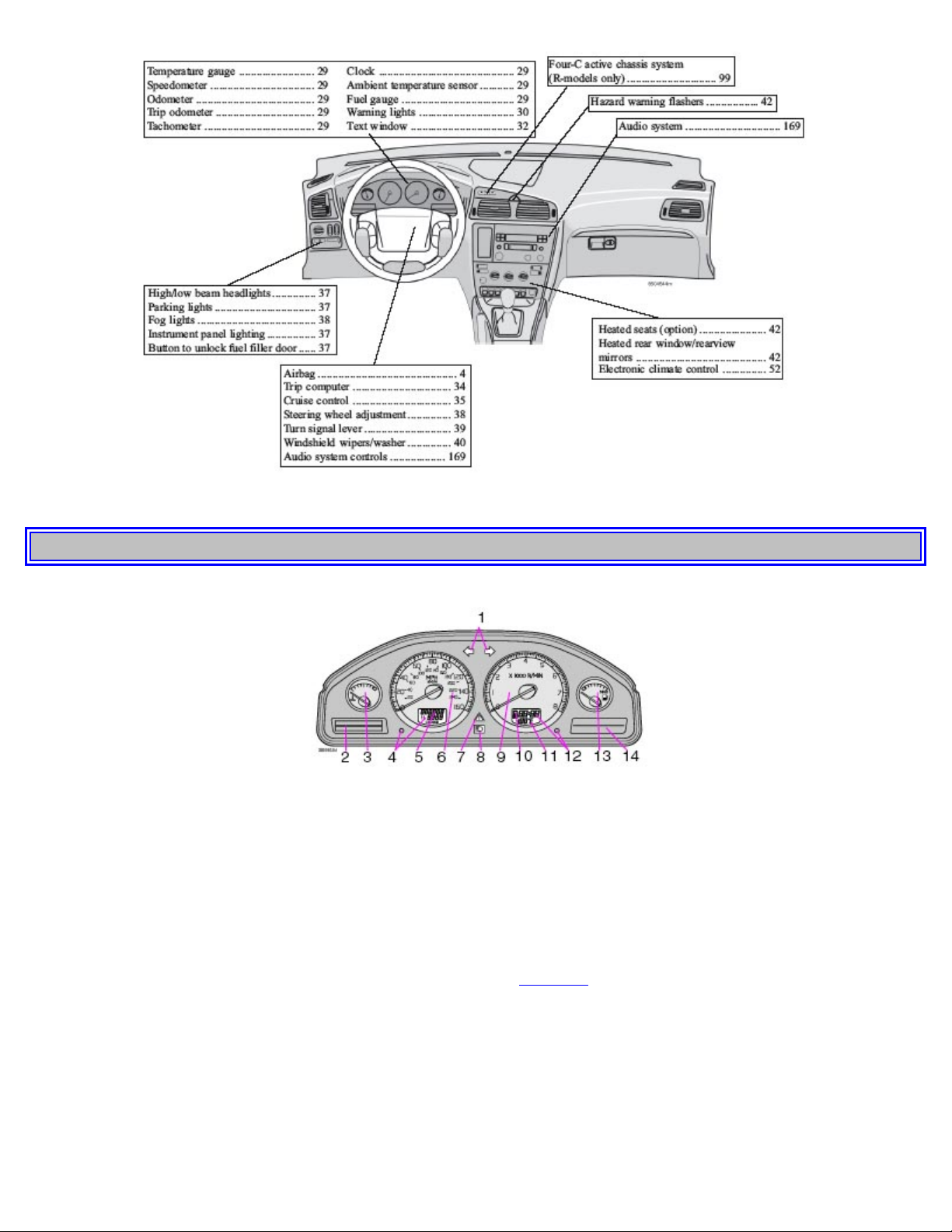
pg. 29 Instrument panel
1 Turn signals
2 Text window
3 Temperature gauge
The pointer should be approximately midway on the gauge when driving.
Do not drive the car if the warning light is on. The text window will provide you with additional information.
If the engine temperature remains high, check coolant level - see page 148.
4 Trip odometer/reset button
The trip odometer is used for measuring shorter distances. The last digit indicates 1/10 mile/kilometer. Press the button
quickly to toggle between trip odometers 1 and 2. Hold in the button for more than 2 seconds to reset.
5 Odometer
6 Speedometer
Page 23
7 General warning light (see page 30).
8 High beam indicator light
9 Tachometer
Indicates engine speed in thousands of rpm. Do not drive for long with the needle in the red section. The engine has an
built-in function preventing too high engine speed. When this function operates, you may discern some pulsation,
which is normal.
10 Gear and driving mode indicator
The currently selected driving mode is displayed here. If you use the Geartronic function on the automatic
transmission, the currently selected gear will be displayed.
11 Ambient temperature indicator
This display indicates the air temperature outside your car. A "snowflake" symbol in the text window is displayed
when the temperature is in the range of 23 - 36° F (-5 - +2° C).
Please note that this symbol does not indicate a fault with your car.
At low speeds or when the car is not moving, the temperature readings may be slightly higher than the actual ambient
temperature.
12 Clock/reset button
Turn the button to adjust the clock.
13 Fuel gauge
The fuel tank holds approximately:
Front wheel drive, non-turbo models - 18.5 US gal. (70 liters)
All turbo models - 18 US gal. (68 liters)
When the warning light comes on there are approximately 1.8 US gal. (8 liters) of fuel remaining.
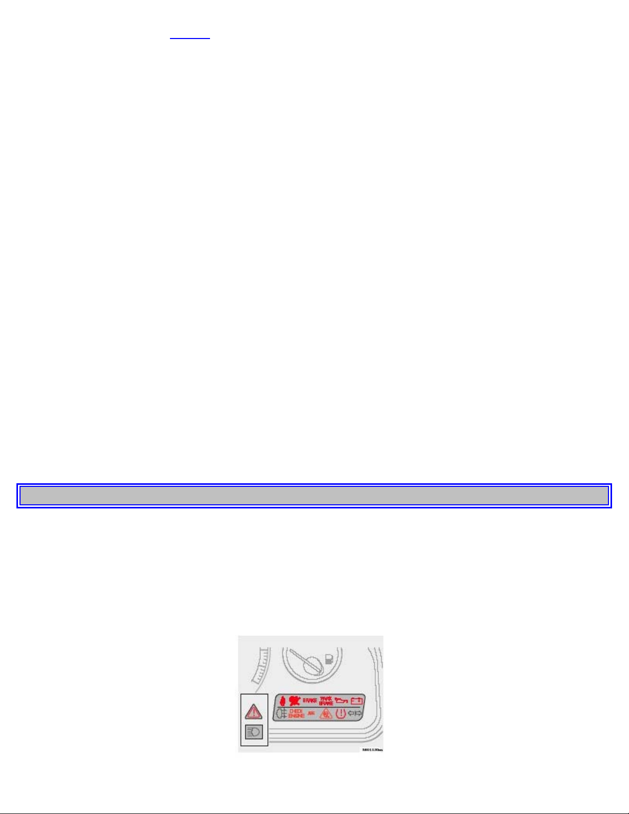
14 Indicator and warning lights
pg. 30 Indicator and warning lights
The indicator and warning lights described on pages 30 and 31 should never stay on when driving*
When the ignition key is turned, all of the warning lights in the lower right-hand side of the instrument panel should
go on to test the function of the bulbs. If a light does not go off after the engine has started, the system indicated
should be inspected.
NOTE: The parking brake reminder light will not go off until the parking brake has been fully released.
Page 24
Warning lamp in the center of the instrument panel
This lamp lights up red or yellow depending on the severity of the fault that has been detected.
Yellow light: Follow the instructions shown in the text window.
Red light: Stop the car as soon as possible in a suitable location and read the message shown in the text window.
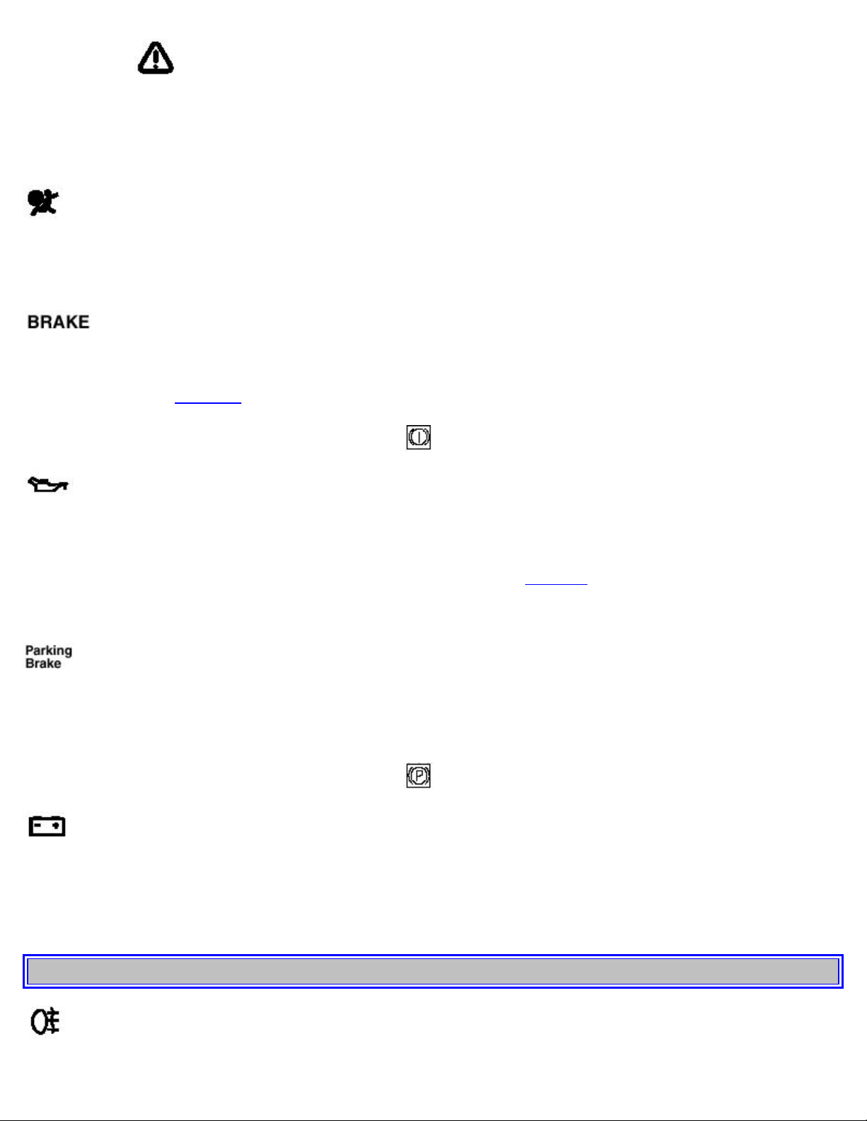
Supplemental Restraint System (SRS)
If the light comes on (or stays on after the vehicle has started), the SRS diagnostic system has detected a fault. Drive to
an authorized Volvo retailer for an inspection of the system. See the SRS section for more information.
Brake failure warning light
If the light comes on while driving or braking, stop immediately, open the hood and check the brake fluid level
in the reservoir. See page 154 for the location of the reservoir.
Canadian models are equipped with this warning light:
Oil pressure warning light
If the light comes on while driving, stop the car and then stop the engine immediately and check the engine oil
level. R-models are also equipped with an oil level warning system. See page 153. If the light stays on after restart,
have the car towed to the nearest authorized Volvo retailer. After hard driving, the light may come on occasionally
when the engine is idling. This is normal, provided it goes off when the engine speed is increased.
Parking brake reminder light
This light will be on when the parking brake (hand brake) is applied. The parking brake lever is situated between the
front seats.
Canadian models are equipped with this warning light:
Generator warning light
If the light comes on while the engine is running, have the charging system checked.
* Rear fog light, if used, and trailer turn signal, if towing a trailer, will go on while driving.
pg. 31 Indicator and warning lights
Page 25

Rear fog light
This light indicates that the rear fog light is on.
Malfunction indicator lamp
On-Board Diagnostic II (OBDII): As you drive, a computer called "OBDII" monitors your car's engine, transmission,
electrical and emission systems. The CHECK ENGINE light will light up if the computer senses a condition that
potentially may need correcting. When this happens, please have your car checked by a Volvo retailer as soon as
possible.
A CHECK ENGINE light may have many causes. Sometimes, you may not notice a change in your car's behavior.
Even so, an uncorrected condition could hurt fuel economy, emission cleanliness, and driveability. Extended driving
without correcting the cause could even damage other components in your car.
Canadian models are equipped with this warning light:
NOTE: If the fuel filler cap is not closed tightly or if the engine is running when the car is refueled, the Malfunction
Indicator Lamp may indicate a fault. However, your vehicle's performance will not be affected. Use only Volvo
original or approved fuel filler caps.
Anti-lock Brake System ABS
If the warning light comes on, there is a malfunction of the ABS system (the standard braking system will still
function). The vehicle should be driven to a Volvo retailer for inspection. See page 21 for additional information.
Stability Traction Control (STC) system (option), or Dynamic Stability and Traction Control (DSTC) system
(option)
An indicator light will flash when STC or DSTC is actively working to stabilize the car. See pages 22-23 for more
detailed information.
Turn signal indicator - trailer (certain models)
If you are towing a trailer, this light will flash simultaneously with the turn signals on the trailer. If the light does not
flash when signaling, neither the trailer's turn signals nor the car's turn signals are functioning.
Seat belt reminder
This symbol lights up to indicate that the driver has not fastened his/her seat belt.
Tire pressure warning light
Page 26
See page 118 for more information on this function.
pg. 32 Text information window
2) OIL LEVEL LOW/STOP ENGINE* Stop as soon as possible and switch off the engine, check the oil level and
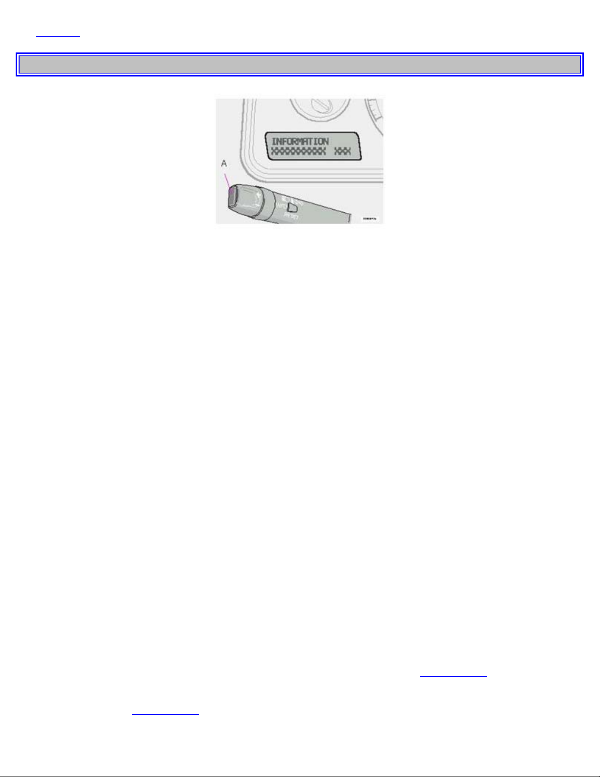
Messages in the text window
When a warning light in the instrument panel comes on, a message is also displayed in the text window. After you
have read the message, you can erase it by pressing button A (see illustration above).
NOTE: Certain messages cannot be erased until the condition has been corrected.
Warning messages override text messages from any car feature that also uses the text window. A warning message
must be acknowledged (erased) before you can access the feature of your choice. Press button A to erase the warning
message.
Erased messages are stored in the system's memory until the required action has been taken. You can scroll through
the stored messages by pressing button A. The text window can be cleared (the message will be returned to memory)
by pressing button A again.
General messages
STOP SAFELY: Stop and switch off the engine - to help prevent serious risk of damage.
STOP ENGINE: Stop and switch off the engine - to help prevent serious risk of damage.
SERVICE URGENT: Take your car to an authorized Volvo retailer for inspection as soon as possible.
SEE MANUAL: Refer to your owner's manual. For additional information, please contact your Volvo retailer.
SERVICE REQUIRED: Take your car to an authorized Volvo retailer for inspection at your convenience (but
preferably before the next scheduled maintenance service).
FIX NEXT SERVICE: Have the system affected inspected at the next scheduled maintenance service.
TIME FOR REGULAR SERVICE: This light will come on at 7,500 mile (12,000 km) intervals, after 750 hours of
driving or after 12 months, whichever occurs first, to remind the driver that the service interval has been exceeded. The
light will stay on for 2 minutes after start until reset by the servicing retailer.
1) OIL LEVEL LOW/FILL OIL* Check the oil level and top up if necessary. See page 151, 153.
2) OIL LEVEL LOW/STOP SAFELY* Stop as soon as possible and switch off the engine, check the oil level and
top up if necessary. See page 151, 153.
Page 27
top up if necessary. See page 151, 153.
2) OIL LEVEL LOW/SEE MANUAL* Stop as soon as possible and switch off the engine, check the oil level and
top up if necessary. See page 151, 153.
* These messages apply to R-models only.
1) Orange warning triangle, see page 30.
2) Red warning triangle, see page 30.
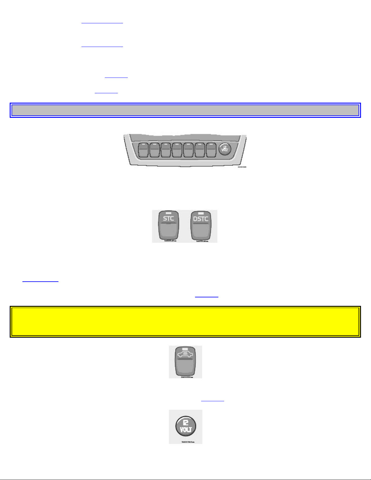
pg. 33 Switches in the center console
The positions of these buttons may vary, depending on the specifications of your car
Stability Traction Control (STC)*/ Dynamic Stability Traction Control (DSTC)**
Press this switch to turn the Spin Control (SC) function of the STC/DSTC system on or off. To help reduce the risk
that the SC function is turned off inadvertently, the switch must be held in for at least half a second to disable this
function.
See pages 22-23 for more information. R-models only:
The Active Yaw Control function can also be deactivated. See page 22 for more information.
WARNING!
Please be aware that the car's handling characteristics may be affected if the Spin Control/Active Yaw Control
functions are switched off.
Disconnecting the alarm
This button is used to temporarily disconnect alarm sensors. See page 85 for further information
Page 28
Auxiliary socket
This 12 volt socket can be used to plug in certain accessories. The ignition key must be in position 1 (or higher) for the
auxiliary socket to function. See also page 43 for more information.
Front/rear park assist (option/accessory)
See page 100 for more information on this function.
Four-C active chassis system: R models only
Please see page 99 for information on adjusting the active chassis settings.
Power child locks (option)
See page 86 for more information on this function.
* Standard on all models except the T5 turbo.
** Standard on the T5 turbo/R-models, optional on all other models.
pg. 34 Trip computer (option)
Trip computer
The trip computer stores information gathered from several systems in your car and has four menus that can be
displayed in the text window.
Driving distance on current fuel reserve
Average fuel consumption
Current fuel consumption
Average speed
Current speed in mph (Canadian models only)
NOTE: Warning messages from the car's monitoring systems will override the trip computer function. If a warning
message is displayed in the text window while you are using the trip computer, you must acknowledge the message by
pressing button A. Press button A again to return to the trip computer function.
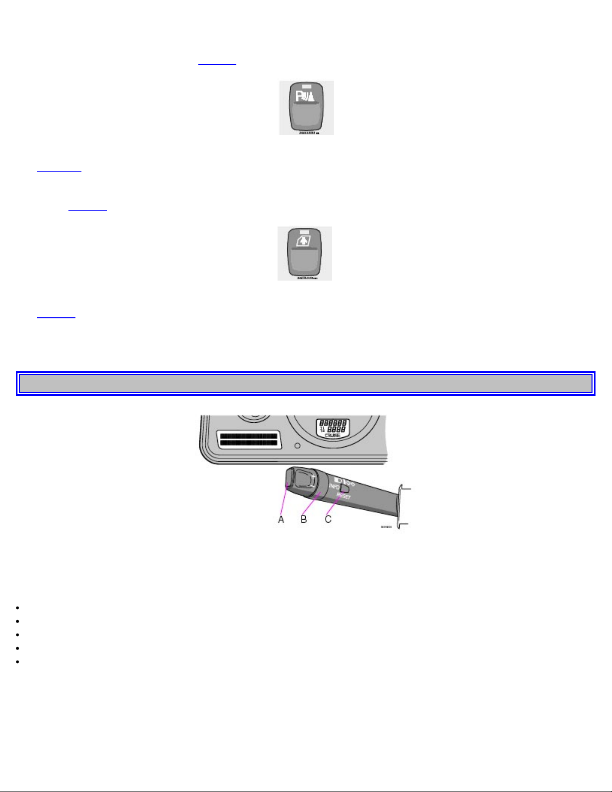
Trip computer controls and functions
Page 29

The four* trip computer functions can be accessed by twisting control B one step at a time in either direction. Twisting
the control a fifth time** returns you to the original function.
The trip computer can be reset (current data will be erased from system memory) by pressing RESET (button C).
1. Driving distance on current fuel reserve
This function shows the approximate distance that can be driven on the fuel remaining in the tank. This calculation is
based on average fuel consumption during the last 12 miles (20 km) of driving and the amount of fuel remaining in the
tank when the reading was taken. When the driving distance on current fuel reserve is less than 12 miles (20 km), "---" will be displayed in the text window.
2. Average fuel consumption
This value indicates fuel consumption since the last time the trip computer was reset (by pressing RESET, button C).
When the engine is switched off, information on fuel consumption is stored and remains in system memory until the
RESET (button C) is pressed again.
3. Current fuel consumption
This value indicates the current fuel consumption, based on readings taken once per second. When the car is not
moving, "----" will be displayed.
4. Average speed
This value indicates average speed since the last time the trip computer was reset (by pressing RESET, button C).
When the engine is switched off, information on average speed is stored and remains in system memory until the
RESET (button C) is pressed again.
5. Current speed in miles per hour (Canadian models only)
This function provides the driver with an instantaneous conversion of the car's current speed from km/h to mph.
NOTE: Trip computer readings may vary slightly depending on the circumference of the tires on the car.
*Five functions on Canadian models
**A sixth time on Canadian models
Contents | Top of Page
Page 30
2 0 0 5
VOLVO
Chapter 3 - Climate control system
pg. 49 Climate control system
Ventilation 50
Climate control system - general information 51
Electronic Climate Control (ECC) 52
Manual climate control with air conditioning, A/C 56
pg. 50 Ventilation
V70
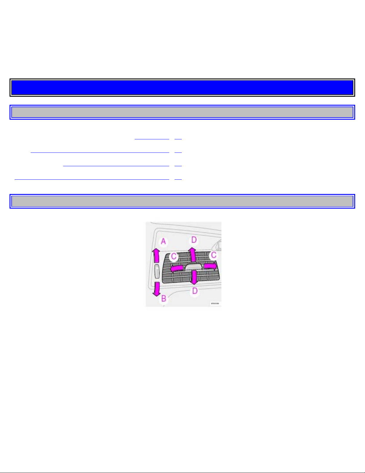
Air vents in dash
Air vents (dash)
A Open
B Closed
C Horizontal air flow
D Vertical air flow
Direct the outer air vents toward the side windows to demist.
Page 31

Air flow
The air that is drawn into the passenger compartment is distributed from 14 ventilation points.
Air vents in door pillars
Air vents in door pillars
A Open
B Closed
C Horizontal air flow
D Vertical air flow
Direct the air vents toward the rear side windows to demist.
Direct the air vents toward the rear seat for the best heating/cooling effect.
pg. 51 Climate control system - general information
Condensation on the inside of the windows
Keeping the insides of the windows clean will help reduce the amount of condensation that forms on the windows. Use
a commercial window cleaning agent to clean the windows.
Ice and snow
Always keep the air intake grille at the base of the windshield free of snow.
Cabin air filter
Replace the cabin air filter with a new one at the recommended intervals. Please refer to your Warranty and Service
Records Information booklet, or consult your Volvo retailer for these intervals. The filter should be replaced more
often when driving under dirty and dusty conditions. The filter cannot be cleaned and therefore should always be
replaced with a new one.
Page 32

Sensors
The sunlight sensor on the dashboard and passenger compartment temperature sensor in the ECC control panel should
not be covered in any way as this could cause incorrect information to be sent to the ECC system.
Parking the car in warm weather
If your car has been parked in the sun in warm weather, opening the windows and moonroof (option) for several
minutes before driving will help release the warm air from the passenger compartment. When the engine is running,
close the windows and moonroof and use the recirculation function for several minutes to enable the air conditioning
to cool the compartment as quickly as possible.
Windows and optional moonroof
The ECC system will function best if the windows and optional moonroof are closed. If you drive with the moonroof
open, we recommend that you manually adjust the temperature and blower control (the LED in the AUTO switch
should be off).
Acceleration
The air conditioning is momentarily disengaged during full-throttle acceleration.
ECC maintenance
All maintenance on the climate control systems should be carried out by an authorized Volvo service technician only.
Refrigerant
Volvo cares about the environment. The air conditioning system in your car contains a CFC-free refrigerant - R134a
(HFC134a). This substance will not deplete the ozone layer. The system contains 2.2 lbs (1000 g) R134a and uses
PAG oil.
Passenger compartment blower
Approximately 50 minutes after the ignition is turned off, the blower may come on automatically, and run for five
minutes, to remove condensation in the A/C evaporator.
pg. 52 Electronic Climate Control (ECC)
pg. 53 Electronic Climate Control (ECC)
Page 33

AUTO
pressed, the climate control system will recirculate the air in the passenger compartment for 5-12 minutes, depending
This function automatically regulates the Electronic Climate Control system so that the selected temperatures are
maintained. The blower, heating, air distribution (air flow) and air conditioning are controlled. If you prefer to
manually set any of these functions, the remaining functions will still be controlled automatically. Pressing the AUTO
button overrides any settings that were previously made manually.
Temperature
These controls are used to individually set the temperature for both sides of the passenger compartment. Please note
that the compartment will not be heated or cooled faster by setting the temperature higher or lower than necessary. Set
the control to the temperature you prefer.
Defroster
This function demists/de-ices the windshield and front side windows. The LED in the switch will light up to indicate
that the defrost function is engaged. Blower speed increases automatically and the air in the passenger compartment is
dehumidified. Recirculation will not function while defrost is engaged.
Heated rear window/sideview mirrors
This function demists/de-ices the rear window and sideview mirrors. The LED in the switch will light up to indicate
that the heating function is engaged. See page 57
CAUTION:
Never use ice scrapers made of metal as they can easily scratch the mirror surface.
for additional information on this function.
pg. 54 Electronic Climate Control (ECC) - manual settings
Recirculation (see also page 55)
Press this switch to engage the recirculation function (air in the passenger compartment recirculates - no fresh air
enters the compartment). The LED in the switch will light up to indicate that the function is engaged.
Use this function if the outside air is contaminated with exhaust gases, smoke, etc or to heat/cool the car quickly.
Recirculation should not be used for more than 15 minutes. If your windows begin to fog or mist, make sure that the
recirculation function is switched off.
Selecting Defroster automatically switches recirculation off.
Timer mode activation: (Cars with Interior Air Quality system have no timer mode) Press and hold the recirculation
button for at least 3 seconds to activate a recirculation timer mode. The amber LED in the recirculation button will
flash 5 times to show that the timer mode is being activated. In the timer mode, each time the recirculation button is
Page 34

on the outside air and then revert back to fresh air.
Timer mode deactivation: Press and hold the recirculation button for at least 3 seconds. The amber LED in the
recirculation button will illuminate steadily for 5 seconds to show a return to "normal" mode.
In normal mode, when the recirculation button is pressed, the climate control system will recirculate the air in the
passenger compartment until the recirculation button is pressed again.
Timer mode memory: If the car is turned off while timer mode is active, timer mode will still be active when the
car is restarted.
Heated front seats (option)
Please see page 42
Press AUTO to automatically regulate air flow or press any combination of the controls shown in the illustration to
manually adjust air flow. An LED in the switch will light up if an air flow control has been pressed.
Press the switch to turn the air conditioning on or off. The "ON" or "OFF" LED will light up to indicate if the system
is switched on or off. Other functions will still be regulated automatically (if the AUTO switch is on).
The air conditioning functions only at temperatures above 32° F (0° C).
While the Defroster function is selected, the air conditioning is temporarily activated to dehumidify the air, even if
you have manually switched the air conditioning off. This will only function if the blower is not switched off.
for more information on this function.
Air conditioning ON/OFF
Blower control
Turn the control clockwise to increase or counterclockwise to decrease the blower speed. Pressing the AUTO switch
will automatically regulate blower speed and override manual adjustment.
NOTE: Turning the blower control counterclockwise as far as possible (an orange LED next to the control will light
up) will turn both the blower and the air conditioning off.
pg. 55 Electronic Climate Control (ECC) with Interior Air Quality system (option)
Interior Air Quality system (option)
Some cars are equipped with a multifilter and air quality sensor. The filter separates gases and particles, thereby
reducing the amounts of odors and contaminants entering the car. The air quality sensor detects increased levels of
contaminants in the outside air. When the Air quality sensor detects contaminated outside air, the air intake closes and
the air inside the passenger compartment is recirculated, i.e. no outside air enters the car. The filter also cleans
recirculated passenger compartment air. When the Air quality sensor is activated, the LED AUT comes on in
Page 35

Operation:
Press to activate the Air quality sensor (normal setting).
Or select one of three functions by pressing .
1. Press : the LED AUT comes on. The Air quality sensor is now activated.
2. Press : no LED is lighted. Recirculation not activated.
3. Press : the LED MAN comes on. Recirculation is now activated.
You can switch between these three functions by repeatedly pressing
Keep the following in mind:
Make it a rule to have the air quality sensor activated at all times.
Recirculation is limited in cold climates to avoid misting up.
If misting occurs, you should deactivate the Air quality sensor.
If the windows mist up, you can also use the windshield and side window defroster functions. See page 53.
The filter should be changed at the intervals listed in the Warranty and Service Records Information booklet.
However, if the car is used in a severely contaminated environment, it may be necessary to change the filter more
frequently.
pg. 56 Manual climate control with air conditioning, A/C
Page 36

pg. 57 Manual climate control with air conditioning, A/C
A/C - ON/OFF
The air conditioning function is engaged by pressing ON and disengaged by pressing OFF. When you select Defroster
, the air conditioning is automatically engaged if the fan is not set to position 0.
Heated front seats (option)
Please see page 42
This function demists/de-ices the rear window and sideview mirrors. The LED in the switch will light up to indicate
that the heating function is engaged. See page 42
CAUTION:
Never use ice scrapers made of metal as they can easily scratch the mirror surface.
Recirculation can be used to shut out stale air, exhaust, etc. from the passenger compartment. The air in the passenger
compartment is then recirculated, i. e. no air from outside the car is taken into the car when this function is activated.
Recirculation (together with the air conditioning system) cools the passenger compartment more quickly in warm
weather.
If you allow the air in the car to recirculate, there is a risk of icing and fogging, especially in winter. The timer function
minimizes the risk of ice, misting and stale air.
Activate the timer function as follows:
for more information on this function.
Heated rear window/sideview mirrors
for additional information on this function.
Recirculation
Press for more that 3 seconds. The LED flashes for 5 seconds. The air recirculates in the car for 3-12
minutes depending on the outside temperature.
The timer function is activated each time you press .
To switch off the timer function :
Press again for more than 3 seconds. The LED lights for 5 seconds to confirm your selection.
Recirculation is always disconnected when you select Defroster .
Blower
Blower speed can be increases or decreased by turning the knob. If the knob is set to 0, the air conditioning function is
automatically disengaged.
Page 37

Temperature
Turn the control to set the temperature for the driver's and passenger's sides of the car. For cooler air, the air
conditioning function must be engaged.
Air distribution
Use the air distribution control positions (marked with dots) between the different symbols to fine-tune air distribution
for the maximum comfort.
pg. 58 Manual climate control with air conditioning, A/C
Air distribution
Contents | Top of Page
Page 38

Chapter 4 - Interior
pg. 59 Interior
Front seats (electrically operated) 60
Front seats (manually operated) 61
Front storage compartments, coat hanger 65
2 0 0 5
VOLVO
V70
Storage compartments 63
Folding table in rear seat 66
Rear seat and cargo area 67
Cargo area 71
Securing cargo 72
Steel grid, cargo net 73
Nylon cargo net - XC70 74
Cargo area cover, vanity mirrors 75
Spare tire 76
Auxiliary seat in cargo area, Extra handgrip - XC70 77
Interior lighting 78
pg. 60 Front seats
Electrically operated seats (option)
Operation
Driver's seat:
The seat can be adjusted if the ignition key is in position I, II or if the engine is running.
It can also be adjusted as follows with the ignition off:
· Within 10 minutes after the driver's door has been unlocked from the outside and has been opened and remains open.
· Within 40 seconds, if the driver's door has just been closed.
· Within 40 seconds, if the driver's door has not been opened after the ignition has been switched off.
Passenger's seat:
The seat can only be adjusted if the ignition key is in position I, II or if the engine is running.
Page 39

Seat adjustment
Adjust the power seat(s) with the controls at the side of the seat as follows:
1 Front edge of seat (raise/lower)
2 Forward - rearward
3 Rear edge of seat (raise/lower)
4 Backrest tilt
Power seat adjustment controls
NOTE: The power seats have an overload protector that activates if a seat is blocked by any object. If this occurs,
switch off the ignition (key in position 0) and wait about 20 seconds before operating the seat again.
Emergency stop
If the seat accidentally begins to move, press any of the buttons to stop the seat.
NOTE: Please refer to the following page for information on programming the memory function in the driver's seat.
Remote keyless entry system and the driver's seat
The remote control transmitter also controls the position of the electrically operated driver's seat in the following way:
1. Adjust the seat to your preferences.
2. When you leave your vehicle, lock it using the remote control.
The position of the seat is now stored in the remote control.
Automatic seat adjustment
To move the seat to the position in which you left it:
1. Unlock the driver's door with the same remote control (the one used to lock the doors).
2. Open the driver's door within 2 minutes.
The driver's seat will automatically move to the position in which you left it.
NOTE:
· The seat will move to this position even if someone else has moved it to a different seating position and locked the
car with a different remote control.
· This feature will work in the same way with all of the remote control transmitters (up to 3) that you use with your
vehicle.
· This feature will not function if your lock your vehicle with the key.
WARNING!
Because the driver's seat can be adjusted with the ignition off, children should never be left unattended in the car.
Movement of the seat can be STOPPED at any time by pressing any button on the power seat control panel.
Do not adjust the seat while driving. The seat should be adjusted so that the brake pedal can be depressed fully. In
addition, position the seat as far rearward as comfort and control allow.
The seat rails on the floor must not be obstructed in any way when the seat is in motion.
pg. 61 Front seats
Page 40

Programming the memory
Programming the driver's seat memory (option)*
Three different seating and door mirror positions can be stored in the driver seat's memory.
The following example explains how button 1 can be programmed.
Buttons 2 and 3 can be programmed in the same way.
To program (store) a seat position in button 1:
1. Move the seat to the desired position using the seat adjustment controls (see the previous page).
2. Press and hold down the MEM (memory) button.
3. With the MEM button depressed, press button 1 briefly to store the seat's current position.
To move the seat to the position that it was in when button 1 was programmed:
Press and hold down button 1 until the seat stops moving.
As a safety precaution, the seat will stop automatically if the button is released before the seat has reached the preset
position.
* This option is only available on the driver's seat.
Manually adjusted front seats
1. Front-rear adjustment: lift the bar and move the seat to the position of your choice.
2. Raise/lower the front edge of the seat cushion (option): use the control to pump the front edge of the cushion up or
down.
3. Raise/lower seat height: pump the seat up or down
4. Lumbar support: turn the control for firmer or softer lumbar support.
5. Backrest tilt: turn the control to adjust the angle of the backrest.
6. Control panel for optional power seat (see page 60 for more information).
WARNING!
Do not adjust the seat while driving. The seat should be adjusted so that the brake pedal can be depressed fully. In
addition, position the seat as far rearward as comfort and control allow.
Page 41

Check that the seat is securely locked into position after adjusting.
pg. 62 Front seats
Folding front seat backrest
The passenger seat backrest can be folded down to the horizontal position for carrying long loads. To fold down the
backrest:
Move the seat as far rearward as possible
Adjust the backrest tilt to the most upright position
Lift the catches on the lower rear side of the backrest
Without releasing the catches, push the backrest forward
Move the seat as far forward as possible so that the head restraint slides under the glove compartment.
WARNING!
Cover sharp edges on the load to help prevent injury to occupants. Secure the load to help prevent shifting during
sudden stops.
pg. 63 Storage compartments
Page 42

1. Storage compartment in door
2. Storage pocket in edge of front seat
3. Ticket clip
4. Glove compartment
5. Storage compartment and cup holders in center console (see the following page for more information)
6. Storage space and cupholders in rear seat armrest
7. Storage pocket in rear side of front seats§
WARNING!
Make sure that no hard, sharp or heavy objects lie on or in any of the storage places where they might cause injury
during heavy braking.
pg. 64 Cup holders, Glove compartment
Storage compartments in the center console
1. Storage compartment cover
2. Front storage compartment
This storage space is fitted with a sliding cover (not on XC70 models)
3. 12-volt socket
4. Space for accessory ashtray
Page 43

Cup holder for rear seat passengers
· To access the storage compartment, press the button on the left side of the armrest and fold the entire cover rearward.
· To open the rear seat cup holder, press the button on the right side of the armrest. Fold the upper section of the cover
rearward.
The two sections of the cover can be closed separately.
Cup holders in the center console
To remove the cup holders:
1. Pull up the rear edge of the cup holder.
2. Move the cup holder rearward.
3. Pull up the front edge of the cup holder and lift it out of the storage space.
Return the cup holder to the storage space in the reverse order.
pg. 65 Front storage compartments, Coat hanger
Pen holder on the center console
Page 44

Storage in the glove compartment
The glove compartment has storage spaces designed specifically to hold credit cards, pens, and pencils.
Coat hanger
Use the coat hanger for light jackets, etc.
pg. 66 Folding table in rear seat
Folding Table (option)
Pull the tab and fold the table section forward.
Page 45

Fold the armrest in the backrest forward. Fold out the table so that it rests on the armrest. Press to release the cup
holder. You do not have to fold the backrest forward, if you only want to use the cup holder.
To close: Fold the table section upward into place. Fold the arm under the table inward being careful not to pinch your
hand. Pull the release and fold the table section back in place.
Contents | Top of Page
Page 46

Chapter 5 - Keys, Locks, Alarm
pg.79 Keys, Locks, Alarm
Keys, Immobilizer, Exterior courtesy lights 80
Remote keyless entry system 81
Unlocking the tailgate, Central locking buttons 83
Alarm 84
Child safety locks - rear doors 86
2 0 0 5
VOLVO
V70
pg. 80 Keys, Immobilizer, Exterior courtesy lights
Keys
Two types of keys are provided with your car; master keys and a service key. The master key, the remote control, and
the central locking button may all be used to lock and unlock all of your car's locks.
The service key operates the driver's door and the ignition switch. It will also fit the tailgate lock cylinder on models
outfitted with a factory installed third seat. The service key is intended to help deter unwanted entry into the glove
compartment.
Turn the key once to unlock the driver's door and the fuel filler door.
Turn the key again (within 10 seconds) to unlock all doors and the tailgate.
One turn with the key towards lock in the drivers door locks all doors and tailgate.
Page 47

Use the switch on the front door armrests to lock/unlock the car from the inside.
WARNING!
If the doors are locked while driving, this may hinder rapid access to the occupants of the car in the event of an
accident. (Also see information on "Child safety locks").
NOTE: To help prevent accidentally locking the keys in the car, the central locking system is designed to unlock the
doors immediately if the key is left in the ignition switch, the car is locked using the lock button on the door and the
door is then closed. A sound from the lock will be audible at this time.
Please note that this function will not unlock the doors if the engine is running.
Immobilizer (start inhibitor)
Each of the keys supplied with your car contains a coded transmitter. The code in the key is transmitted to an antenna
in the ignition switch where it is compared to the code stored in the start inhibitor module. The car will start only with
a properly coded key.
If you misplace a key, take the other keys to an authorized Volvo retailer for reprogramming as an antitheft measure.
*This key operates only driver's door and ignition switch/steering wheel lock.
This device complies with part 15 of the FCC rules. Operation is subject to the following condition: (1) This device
may not cause harmful interference, and (2) this device must accept any interference received, including interference
that may cause undesired operation.
Exterior courtesy lights
Home Safe System
When you leave your car at night, you can make use of the courtesy lighting function:
Remove the key from the ignition switch.
Pull the direction indicator lever towards the steering wheel (as when activating the high beams).
Exit the car and lock the doors.
The headlights, parking lights, license plate lights and the lights in the sideview mirrors will now come on and remain
on for 30, 60 or 90 seconds (the time interval is at your discretion and can be changed by an authorized Volvo retailer).
Approach lighting
When approaching the car at night, press the yellow button in the central locking remote control (see illustration on
page 81). This lights up the interior courtesy light, parking lights, license plate lights and the lights in the sideview
mirrors.
pg. 81 Remote keyless entry system
Page 48

Remote keyless entry system
NOTE:
Your car is equipped with two coded remote control transmitters with integrated ignition keys called Key Integrated
Remote (KIR). These transmitters use a radio frequency that will enable you to lock/unlock all doors and the tailgate
from a distance of 10-15 feet (3-5 meters).
The transmitters will also activate or allow "keyless" entry into the passenger compartment or the tailgate. They will
also activate or deactivate the vehicle's alarm system(s).
The car can also be locked/unlocked with the key.
If one of the transmitters is misplaced, contact your nearest authorized Volvo retailer for replacement.
Buttons in remote control
1 - Fold key in/out, 2 - Lock, 3 - Approach lighting
4 - "Panic" function *, 5 - Unlock tailgate, 6 - Unlock
Using the remote control
Button 1: Press to extend the key. This button must also be pressed when the key is folded back into the slot in the
side of the remote control unit.
Button 2 (Lock): Press once to lock all doors, and the tailgate.
Button 3 (Approach lighting): Press this button when approaching the car at night to light up the interior courtesy
light, parking lights, license plate lights and the lights in the sideview mirrors.
Button 4 (Panic): See page 84 for more information on this function.
Button 5 (Tailgate unlock): Press this button twice within 3 seconds to unlock the tailgate (without unlocking the
other doors).
Button 6 (Unlock): Press this button once to unlock the driver's door only. Wait for at least 1 second and press the
button again (within 10 seconds) to unlock all doors, and the tailgate.
Page 49

If the doors are unlocked with the remote, the locks will automatically reengage (re-lock) and the alarm will reset
after 2 minutes unless a door has been opened.
The lock/unlock and alarm features can also be utilized by using the keys.
FCC ID:LQNP2T-APU
This device complies with part 15 of the FCC rules. Operation is subject to the following conditions: (1) This device
may not cause harmful interference, and (2) this device must accept any interference received, including interference
that may cause undesired operation.
Canadian 2306104388
Model 504 2927 by Donnelly
Operation is subject to the following conditions: (1) this device may not cause interference, and (2) this device must
accept any interference, including interference that may cause undesired operation of the device.
Canadian 2306104388A
Model 509 977 by Connaught Electronics
Operation is subject to the following conditions: (1) this device may not cause interference, and (2) this device must
accept any interference, including interference that may cause undesired operation of the device.
pg. 82 Remote keyless entry system
Remote keyless entry system - replacing batteries
If the range of the transmitter is noticeably reduced, this indicates that the battery is weak and should be replaced.
To replace the battery
Remove the cover by carefully prying up its rear edge with a small screwdriver
Replace the battery with a new 3-volt, CR 2032 battery. The battery should be inserted with the plus side upward.
Avoid touching the contact surfaces of the battery with your fingers.
Press the cover back into place. Ensure that the rubber seal seats correctly to help prevent moisture from entering the
unit.
NOTE: The old battery should be disposed of properly at a recycling center or at your Volvo retailer.
WARNING!
Volvo does not recommend using the transmitter to lock the doors from inside the car. The alarm would be activated
Page 50

and would sound when one of the doors is opened. The doors must not be locked using the remote transmitter while
the vehicle is occupied. In case of an accident, this may hinder rapid access to the occupants of the vehicle. The
alarm will also sound.
pg. 83 Locking and unlocking the car
Unlocking the tailgate
The tailgate lock is incorporated in the central locking system and is locked or unlocked when the driver's door is
locked/unlocked.
The tailgate can be unlocked by:
Pressing UNLOCK on the remote control twice.
Using the central locking button on the driver's door.
Pressing twice on the remote control's tailgate unlock button (see illustration on page 81).
Relock the tailgate using the remote's "Lock" button.
Automatic relocking:
If you use the tailgate unlock button to unlock the tailgate without opening it, it will automatically relock after
approximately 2 minutes.
NOTE: Please be aware that if the tailgate is unlocked using the tailgate unlock button, opened, and closed again, it
will remain unlocked and the alarm will not be rearmed.
Press the lock button on the remote control to relock the tailgate and rearm the alarm.
Central locking buttons
Central locking buttons
These buttons (located on the both front door armrests) can be used to lock/unlock all doors and the tailgate and set
the alarm.
The rear passenger doors can also be locked and unlocked with the individual lock buttons on each door.
pg. 84 Alarm
Alarm
The alarm is automatically armed whenever you lock your car. When armed, the alarm continuously monitors a
number of points on the car. The following conditions will set off the alarm:
The hood is forced open.
The tailgate is forced open.
Page 51

A door is forced open.
The ignition switch is tampered with.
FCC ID: MAYDA5823
If there is movement in the passenger compartment (if the car is equipped with the optional movement sensor).
The car is lifted or towed (if the car is equipped with the optional inclination sensor).
The battery is disconnected (while the alarm is armed).
Arming the alarm
Press the LOCK button on the remote control, lock the car using the key in the driver's door or press the central lock
button on one of the front doors with the door open. One long flash of the turn signals will confirm that the alarm is
armed.
Disarming the alarm
Press the UNLOCK button on the remote control or unlock the doors with the key.
Turning off (stopping) the alarm
If the alarm is sounding, it can be stopped by pressing the UNLOCK button on the remote control or by unlocking the
driver's door with the key.
Visual alarm signal
The visual alarm signal is given by flashing all turn signals and turning on the interior lighting for approximately 5
minutes.
Audible alarm signal
An audible alarm signal is given by a battery powered siren. One alarm cycle lasts for 25 seconds.
"Panic" button
In an emergency situation, this feature can be used to attract attention. Activate the "panic" function by pressing the
red button on the remote control (see illustration on page 81) for at least 3 seconds or by pressing this button twice
within 3 seconds. The turn signals will flash, the interior lights will go on and the car's horn will sound.
The function can be turned off by pressing any of the buttons on the remote control or will stop automatically
after 25 seconds. When a button is pressed, there is a 5 second delay before the panic alarm is deactivated.
NOTE: This function will NOT unlock the car.
pg. 85 Alarm
Temporarily turning off the inclination and movement alarm sensor(s) - accessory
This button will only be found in cars equipped with the accessory inclination and/or movement sensors.
Page 52

This device complies with part 15 of the FCC rules. Operation is subject to the following conditions: (1) This device
may not cause harmful interference, and (2) this device must accept any interference received, including interference
that may cause undesired operation.
Canadian IC: 4405A-DA5823
Movement sensor DA5823 by Dynex
Operation is subject to the following conditions: (1) this device may not cause interference, and (2) this device must
accept any interference, including interference that may cause undesired operation of the device.
In certain situations it may be desirable to turn off the inclination and movement alarm sensors if, for example, you
drive your car onto a ferry where the rocking of the boat could trigger the alarm or if a pet is left in the car with the
doors locked.
To temporarily turn off the inclination and movement alarm sensors from the alarm system:
From the time the ignition key is turned from the Drive position (position II) until you lock the car, you can press the
button in the center console. The LED in the switch will light up and a message will be displayed in the text window
to indicate that the sensors are disconnected.
The car can then be locked in the usual way to set the alarm.
NOTE:
This function will not turn off the vehicle's standard alarm.
The optional sensors are automatically reconnected to the alarm system the next time the car is unlocked and then
locked again.
LED alarm status signals
The status of the alarm system is indicated by the red LED at the top of the dash:
LED off - the alarm is not armed
LED flashes once per second - the alarm is armed
LED flashes rapidly before the ignition is switched on - the alarm has been triggered
Fault in the alarm system: If a fault has been detected in the alarm system, a message will be displayed in the text
window. Contact a Volvo retailer.
Automatic re-lock/re-arm system
If the car is unlocked with the remote, the car will re-lock and the alarm will re-arm after 2 minutes unless a door or
the tailgate has been opened.
pg. 86 Child safety locks - rear doors
Page 53

Child safety lock control in left rear door Child safety lock control in right rear door
Child safety locks - rear doors
The controls are located on the rear door jambs*. Use the ignition key or a screwdriver to adjust these controls.
A The door cannot be opened from the inside. Normal operation from the outside.
B The door lock functions normally.
* Vehicles equipped with the optional rear-facing auxiliary child seat in the cargo area also have a child safety lock on
the underside of the tailgate. This lock is visible when the tailgate is open.
WARNING!
Remember, in the event of an accident, the rear seat passengers cannot open the doors from the inside with the
buttons in position A.
Power child safety lock button
Power child safety locks (option)
To prevent the rear doors from being opened from the inside:
1. Turn the vehicle's ignition key to at least position 1.
2. Press the button shown above.
Indicator light in the button ON: the doors cannot be opened from the inside. Normal operation from the outside.
Indicator light in the button OFF: the doors can be opened from the inside.
NOTE: On vehicles equipped with the optional rear-facing auxiliary child seat in the cargo area, the child safety lock
in the tailgate must be activated or deactivated manually.
Page 54

Contents | Top of Page
Page 55

Chapter 6 - Starting and driving
Fuel requirements
pg. 87 Starting and driving
Fuel requirements 88
Fuel Formulations 89
Refueling 90
Starting the engine 91
Manual transmission 93
Automatic transmission (AW5) 94
2 0 0 5
VOLVO
V70
Automatic transmission (Geartronic) 96
All Wheel Drive 98
Four-C active chassis system 99
Front/rear park assist (option/accessory) 100
Driving economy, Handling 101
Points to remember 102
Roof racks/load carriers 103
Emergency towing 105
Vehicle towing information 106
Towing a trailer 107
Detachable trailer hitch 108
Jump starting 109
Winter driving 110
Three-way catalytic converter 112
pg. 88 Fuel requirements
Long distance trips 111
Page 56

Octane rating: Volvo engines are designed for optimum performance on unleaded premium gasoline with an octane
rating AKI of 91, or above. AKI (ANTI KNOCK INDEX) is an average of the Research Octane Number, RON, and
the Motor Octane Number, MON. (RON + MON/2). The minimum octane requirement is AKI 87 (RON 91).
Deposit control gasoline (detergent additives)
Volvo recommends the use of detergent gasoline to control engine deposits. Detergent gasoline is effective in keeping
injectors and intake valves clean. Consistent use of deposit control gasolines will help ensure good driveability and
fuel economy. If you are not sure whether the gasoline contains deposit control additives, check with the service
station operator.
Unleaded fuel
Each Volvo has a three-way catalytic converter and must use only unleaded gasoline. U.S. and Canadian regulations
require that pumps delivering unleaded gasoline be labelled "UNLEADED". Only these pumps have nozzles which fit
your car's filler inlet. It is unlawful to dispense leaded fuel into a vehicle labelled "unleaded gasoline only". Leaded
gasoline damages the three-way catalytic converter and the heated oxygen sensor system. Repeated use of leaded
gasoline will lessen the effectiveness of the emission control system and could result in loss of emission warranty
coverage. State and local vehicle inspection programs will make detection of misfueling easier, possibly resulting in
emission test failure for misfueled vehicles.
NOTE: Some U.S. and Canadian gasolines contain an octane enhancing additive called methyl-cyclopentadienyl
manganese tricarbonyl (MMT). If such fuels are used, your Emission Control System performance may be affected,
and the Check Engine light (malfunction indicator lamp) located on your instrument panel may light. If this occurs,
please return your vehicle to an authorized Volvo retailer for service.
Gasoline containing alcohol and ethers
"Oxygenated fuels"
Some fuel suppliers sell gasoline containing "oxygenates" which are usually alcohols or ethers. In some areas, state or
local laws require that the service pump be marked indicating use of alcohols or ethers.
However, there are areas in which the pumps are unmarked. If you are not sure whether there is alcohol or ethers in the
gasoline you buy, check with the service station operator. To meet seasonal air quality standards, some areas require
the use of "oxygenated" fuel.
Volvo allows the use of the following "oxygenated fuels; however, the octane ratings listed on this page must still be
met.
Alcohol - Ethanol: Fuels containing up to 10% ethanol by volume may be used. Ethanol may also be referred to as
Ethyl alcohol, or "Gasohol".
Ethers - MTBE: Fuels containing up to 15% MTBE may be used.
CAUTION! Do not use gasolines containing methanol (methyl alcohol, wood alcohol). This practice can result in
vehicle performance deterioration and can damage critical parts in the fuel system. Such damage may not be covered
under the New Vehicle Limited Warranty.
pg. 89 Fuel requirements
Carbon Monoxide - Important Warning
Carbon monoxide is a poisonous, colorless, and odorless gas. It is present in all exhaust gases. If you ever smell
exhaust fumes inside the vehicle, make sure the passenger compartment is ventilated, and immediately return the
vehicle to your retailer for correction.
Page 57

Fuel Formulations
Do not use gasoline that contains lead as a knock inhibitor, and do not use lead additives. Besides damaging the
exhaust emission control systems on your car, lead has been strongly linked to certain forms of cancer.
Many fuels contain benzene as a solvent. Unburned benzene has been strongly linked to certain forms of cancer. If you
live in an area where you must fill your own gas tank, take precautions. These may include:
standing upwind away from the filler nozzle while refueling
refueling only at gas stations with vapor recovery systems that fully seal the mouth of the filler neck during refueling
wear neoprene gloves while handling a fuel filler nozzle.
Use of Additives
With the exception of gas line antifreeze during winter months, do not add solvents, thickeners, or other store-bought
additives to your car's fuel, cooling, or lubricating systems. Overuse may damage your engine, and some of these
additives contain organically volatile chemicals. Do not needlessly expose yourself to these chemicals.
pg. 90 Refueling
Refueling
The fuel tank holds approximately:
Front wheel drive, non-turbo models - 18.5 US gal. (70 liters)
All turbo models - 18 US gal. (68 liters)
with sufficient volume left over to accommodate possible expansion of the fuel in hot weather. Be aware that the
"usable" tank capacity will be somewhat less than the specified maximum. When the fuel level is low, such factors as
ambient temperature, the fuel's "Reid vapor pressure" characteristics, and terrain can affect the fuel pump's ability to
supply the engine with an adequate supply of fuel. Therefore, it is advisable to refuel as soon as possible when the
needle nears the red zone, or when the fuel warning light comes on.
Fuel filler door
Press the button on the light switch panel (see illustration on page 37) when the car is at a standstill to unlock the fuel
filler door. Please note that the fuel filler door will remain unlocked until the car begins to move forward. An audible
click will be heard when the fuel filler door relocks.
If you intend to leave your car while it is being refueled, this features enables you to lock the door/tailgate while
leaving the fuel filler door unlocked.
You can also keep the car locked if you remain inside it during refueling. The central locking button does not lock the
fuel filler door.
Be sure the fuel filler door is not obstructed and is completely closed after refueling.
Open the fuel filler cap slowly during hot weather conditions.
NOTE: During a transitional period, a small number of service stations may still have fuel nozzles that are not
compatible with the fuel filler neck on cars equipped with the evaporative control system. Please refer to page 147 for
Page 58

additional information.
WARNING!
Never carry a cell phone that is switched on while refueling your vehicle. If the phone rings, this may cause a spark
that could ignite gasoline fumes, resulting in fire and injury.
CAUTION:
Do not refuel with the engine running *. Turn the ignition off or to position I. If the ignition is on, an incorrect
reading could occur in the fuel gauge.
After refueling, close the fuel filler cap by turning it clockwise until it clicks into place *.
Allow for fuel expansion by not overfilling the tank. Overfilling could also cause damage to the emission control
systems.
Avoid spilling gasoline when refueling. In addition to causing damage to the environment, gasolines containing
alcohol can cause damage to painted surfaces, which may not be covered under the New Vehicle Limited Warranty.
Do not use gasolines containing methanol (methyl alcohol, wood alcohol). This practice can result in vehicle
performance deterioration and can damage critical parts in the fuel system. Such damage may not be covered under the
New Vehicle Limited Warranty.
* If the fuel filler cap is not closed tightly or if the engine is running when the car is refueled, the Check Engine light
(malfunction indicator lamp) may indicate a fault. However, your vehicle's performance will not be affected. Use only
Volvo original or approved fuel filler caps.
pg. 91 Starting the engine
Starting the engine
1. Fasten the seat belt.
WARNING!
Before starting, check that the seat, steering wheel and mirrors adjusted properly.
Make sure the brake pedal can be depressed completely. Adjust the seat if necessary. See page 60.
2. Apply the parking brake, if not already set. The gear selector (automatic transmission) is locked in the (P)ark
position (SHIFT-LOCK).
Manual transmission: the clutch must be fully depressed.
3. Without touching the accelerator pedal, turn the ignition key* to the starting position. Allow the starter to operate
for up to 10 seconds. Release the key as soon as the engine starts. If the engine fails to start, repeat this step.
For cold starts at altitudes above 6000 ft (1800 meters), depress the accelerator pedal halfway and turn the key to the
starting position. Release the pedal slowly when the engine starts.
NOTE:
On certain models, when the car is started, idle speed may be noticeably higher than normal for a short period,
depending on the temperature of the engine.
This has been done to help bring components in the emission control system to their normal operating temperature as
quickly as possible, which enables them to function normally.
For cold starts at altitudes above 6000 ft (1800 meters), depress the accelerator pedal halfway and turn the key to the
starting position. Release the pedal slowly when the engine starts.
4. To release the gear selector from the (P)ark position, the engine must be running (or the ignition key must be in
position II) and the brake pedal must be depressed. While keeping firm pressure on the brake pedal, release the parking
brake.
Page 59

5. Select the desired gear. The gear engages after a very slight delay which is especially noticeable when selecting R.
NOTE:
Your car is equipped with a KEYLOCK system. When the engine is switched off, the gear selector must be in the
(P)ark position before the key can be removed from the ignition switch.
When starting in cold weather, the transmission may shift up at slightly higher engine speeds than normal until the
automatic transmission fluid reaches normal operating temperature.
* Your car is equipped with an electronic start inhibitor (immobilizer). The keys you received with your car are
specially coded. The code in the key is transmitted to an antenna in the ignition switch where it is compared to the
code stored in the start inhibitor module. The car can only be started if a properly coded key is used.
If two of the keys to your car are close together, e.g., on the same key ring, when you try to start the car, this could
cause interference in the immobilizer system and result in the car not starting. If this should occur, remove one of the
keys from the key ring before trying to start the car again.
pg. 92 Starting the engine
CAUTION:
The engine should be idling when you move the gear selector. Never accelerate until after you feel the transmission
engage! Accelerating immediately after selecting a gear will cause harsh engagement and premature transmission wear.
Selecting P or N when idling at a standstill for prolonged periods time will help prevent overheating of the automatic
transmission fluid.
Do not race a cold engine immediately after starting. Oil flow may not reach some lubrication points fast enough to
prevent engine damage.
WARNING!
Always place the gear selector in Park or in reverse on models with a manual transmission, and apply the parking
brake before leaving the vehicle. Never leave the car unattended with the engine running.
Always open garage doors fully before starting the engine inside a garage to ensure adequate ventilation. The
exhaust gases contain carbon monoxide, which is invisible and odorless but very poisonous.
An extra mat on the driver's floor can cause the accelerator pedal and the clutch to catch. Check that the movement
of the accelerator pedal and clutch is not impeded. Not more than one protective floor covering may be used at one
time.
pg. 93 Manual transmission
Page 60

5-speed manual transmission
Depress the clutch pedal completely when changing gears*.
Remove your foot from the clutch pedal while driving. The shift pattern should be followed.
Overdrive (5th gear) should be used as often as possible to help improve fuel economy. This gear should be engaged at
speeds above approx. 50 mph (80 km/h).
* Clutch interlock
The clutch must be fully depressed before you can start your car. If the clutch is not depressed, it will not be possible
to start the engine.
6-speed manual transmission (option on certain models)
Fifth and sixth gears should be used as often as possible to help improve fuel economy.
WARNING!
An extra mat on the driver's floor can cause the accelerator pedal and/or the clutch pedal to catch. Check that the
movement of these pedals is not impeded. Not more than one protective floor covering may be used at one time.
Page 61

Engaging reverse gear
Never engage R while the car is moving.
CAUTION: Be careful that you do not inadvertently engage reverse while moving forward.
pg. 94 Automatic transmission AW5
P (Park)
Use this position when starting the engine or parking the car.
Never use P while the car is in motion.
The parking brake should be set whenever the car is parked.
The gear selector is mechanically locked in the P position (SHIFTLOCK). To release the gear selector from this
position, the engine must be running (or the ignition key must be in position II) and the brake pedal must be
depressed.
WARNING!
Never leave the car unattended when the engine is running. If, by mistake, the gear selector is moved from P, the car
may start moving.
R (Reverse)
Never engage R while the car is moving.
N (Neutral)
Neutral - no gear engaged. Use the parking brake.
D (Drive)
D is the normal driving position and should be used as often as possible to help improve fuel economy. The car should
not be moving when shifting from R to the D position.
4 (Intermediate gear)
The transmission will shift automatically between gears 4, 3, 2 or 1 from this position. The transmission cannot shift
up to (D)rive from fourth gear.
3 (Intermediate gear)
The transmission will shift automatically between gears 3, 2 and 1 from this position. The transmission cannot shift
up to fourth gear or (D)rive from third gear.
Page 62

L (Low gears)
The transmission is locked in gears 1 and 2 when the selector is in this position.
NOTE:
Gears 4, 3, or L can be used if you are driving in a mountainous area, towing a trailer or to increase engine braking
effect.
The transmission has a built-in limiter designed to help prevent excessive engine speeds (high rpm) when gears 4, 3
or L are selected.
Automatic transmission - adaptive system
The automatic transmission is controlled by an adaptive control system that constantly monitors the way in which the
transmission functions. It senses and adapts each gear shift for optimal performance.
pg. 95 Automatic transmission AW5
Automatic transmission - shift gate positions
The gear selector can be moved freely between N and D.
Depressing the button on the front of the gear selector knob enables you to move the gear selector to positions P, R, N,
D, 4, 3 and L.
W Winter/Wet driving mode - enhanced vehicle traction
Mode W will only function if the gear selector is in the (D)rive position.
Press the button at the base of the gear selector to engage/disengage this driving mode (see illustration).
An LED in the button will light up to indicate that W is engaged and this will also be displayed in the instrument
panel (see page 29).
Page 63

This mode may be selected for starting/moving off on slippery roads.
NOTE: R-models are not equipped with this button.
Kickdown
Automatic shift to a lower gear (kickdown) is achieved by depressing the accelerator pedal fully and briskly. An
upshift will occur when approaching the top speed for a particular gear or by releasing the accelerator pedal slightly.
Kickdown can be used for maximum acceleration or when passing at highway speeds.
Cold starts
When driving before the engine has reached its normal operating temperature, the transmission will shift up at slightly
higher engine speeds to heat the three-way catalytic converter as quickly as possible.
pg. 96 Automatic transmission (Geartronic)
P (Park)
Use this position when starting the engine or parking the car.
Never use P while the car is in motion. The parking brake should be set whenever the car is parked.
The gear selector is mechanically locked in the P position (SHIFTLOCK). To release the gear selector from this
position, the engine must be running (or the ignition key must be in position II) and the brake pedal must be
depressed.
WARNING!
Never leave the car unattended when the engine is running. If, by mistake, the gear selector is moved from P, the car
may start moving.
R (Reverse)
Never engage R while the car is moving forward.
N (Neutral)
Neutral - no gear engaged. Use the parking brake.
D (Drive)
D is the normal driving position and should be used as often as possible to help improve fuel economy. The car should
not be moving when shifting from R to the D position.
Kickdown
Automatic shift to a lower gear (kickdown) is achieved by depressing the accelerator pedal fully and briskly. An
Page 64

upshift will occur when approaching the top speed for a particular gear or by releasing the accelerator pedal slightly.
Kickdown can be used for maximum acceleration or when passing at highway speeds. Kickdown does not function
when the transmission is in the manual shift (geartronic) mode (see next page).
Automatic transmission - adaptive system
The automatic transmission is controlled by an adaptive control system that constantly monitors the way in which the
transmission functions. It senses and adapts each gear shift for optimal performance.
Shift gate positions
Automatic transmission - shift gate positions
You can move the gear selector freely between the (MAN)ual and (D)rive positions while driving.
Depress the button on the front of the gear selector knob to move between the R, N, D, and P positions.
Please see the following page for information on using the Geartronic manual shift mode.
pg. 97 Automatic transmission (Geartronic)
Manual shifting - Geartronic
You can move the gear selector freely between the (MAN)ual and (D)rive positions while driving. Gears 2, 3, and 4
have a "lock-up" function which reduces engine speed and helps save fuel.
The currently selected gear will be displayed in the instrument panel (see page 29).
To access the (MAN)ual shifting position from (D)rive, pull the gear selector back slightly from D and move it to
the left to MAN.
To return to the (D)rive position from MAN, move the gear selector to the right and push it forward to the (D)rive
position.
While driving
If you select the (MAN)ual position while driving, the gear that was being used in the (D)rive position will also
initially be selected in (MAN)ual position.
Move the gear selector forward (toward "+") to shift to a higher gear or rearward (toward "-") to shift to a lower
gear.
If you hold the gear selector toward "-", the transmission will downshift one gear and will utilize the braking power
of the engine. If the current speed is too high for using a lower gear, the downshift will not occur until the speed has
decreased enough to allow the lower gear to be used.
If you slow down to a very low speed, the transmission will automatically shift down.
When starting in the (MAN)ual position, 3rd gear is the highest gear that may be selected.
NOTE: Kickdown (see previous page) does not function when the transmission is in the manual shift (geartronic)
Page 65

mode. The gear selector must be in the D (Drive) position.
W Winter/Wet driving mode - enhanced vehicle traction
Please refer to the information on page 95 .
Sport mode (R-models only)
R-models are equipped with a (S)port button that can be used to engage/disengage the Sport shifting mode. An
indicator light in the button will go on when Sport mode is engaged.
With Sport mode engaged, the transmission will shift up at higher rpm in first and second gears, and will also shift
down at higher rpm for more immediate engine response during acceleration and deceleration.
pg. 98 All Wheel Drive - option
All Wheel Drive (AWD) - general information
Your Volvo can be equipped with permanent All Wheel Drive, which means that power is distributed automatically
between the front and rear wheels. Under normal driving conditions, most of the engine's power is directed to the front
wheels. However, if there is any tendency for the front wheels to spin, an electronically controlled coupling distributes
power to the wheels that have the best traction.
Tire dimensions
Volvo recommends that you always drive on tires of the same brand, size, construction (radial), tread pattern, load-,
speed-, traction-, temperature-, and treadwear rating. Never drive on mixed tires, except for brief periods when the
temporary spare tire is in use.
Always use properly inflated tires of correct dimensions. Tire size and inflation pressures are shown on the tire
inflation pressure placards, located on the driver's side B-pillar (the structural member at the side of the vehicle, at the
rear of the driver's door opening), or on the inside of the fuel filler door on Canadian models.
Temporary Spare
The temporary spare tire is for temporary, low-speed, short-distance use only. Replace it with a full-sized tire as soon
as possible. Do not drive on the temporary spare at speeds above 50 m.p.h. (80km/h) or for distances greater than 50
miles (80 km).
Never install snow chains on a temporary spare.
pg. 99 Four-C active chassis system (R-models only)
Page 66

Four-C
R-models are equipped with the Four-C (Continuously Controlled Chassis Concept) system.
This system is based on a number of sensors that continuously monitor factors such as the car's lateral and vertical
movements, speed, and movements of the wheels. The sensors receive data up to 500 times per second, which is used
to provide extremely fast and precise adjustment of each shock absorber. The system adjusts the stiffness of the shock
absorbers approximately 100 times per second.
The buttons in the center of the dashboard (see the illustration above) can be used at any time to switch between three
driving modes: Comfort, Sport, or Advanced sport.
The system then adjusts the stiffness of the shock absorbers accordingly, for example when the type of road changes,
or if the driver wishes to change driving style. This adjustment takes place instantaneously.
The effect of pressure on the throttle pedal is linked to the selected mode, where the Advanced sport setting provides
the most immediate throttle response.
Comfort
The Comfort mode chassis setting offers the greatest amount of shock absorption and the softest ride. This mode is
recommended for long-distance driving, or when driving in slippery conditions.
If Comfort mode was selected when the engine was switched off, this mode will still be active when the engine is
restarted.
Sport
In this mode, shock absorption is stiffer to reduce the car's body sway during cornering and to provide more immediate
steering response.
If this setting was selected when the engine was switched off, Sport mode still will be active when the engine is
restarted.
Advanced sport
In this mode, movement of the shock absorbers is minimal, response from pressure on the throttle pedal is more direct,
and body sway in curves or when cornering is sharply reduced.
If Advanced sport mode was selected when the engine was switched off, Sport mode will be active when the engine
is restarted.
Page 67

pg. 100 Front/rear park assist (option/accessory)
system's sensors.
A - front (accessory as available), B - rear (option)
Front/rear park assist
The park assist system(s) are designed to assist you when driving into parking spaces, garages, etc. They utilize
ultrasound sensors located in the bumpers to measure the distance to a vehicle or other object, or a person who may be
close to the front or rear of the vehicle.
When is park assist active?
Front: the system is active from the time the engine is started until the car exceeds a speed of approximately 10 mph
(15 km/h).
Rear: when the engine is running and reverse gear is selected.
NOTE:
If the vehicle is equipped with front and rear park assist, both systems will either be activated or deactivated
together. They cannot be used separately.
The indicator light in the button (see the illustration on page 33) will light up to indicate that park assist system(s)
are activated.
When park assist is actively working:
1. The audio system's volume will be reduced.
2. An intermittent signal will be audible from the speakers to indicate that you are approaching a person, object,
parked vehicle, etc.
The signals begin when the distance between the bumper and the object is:
Rear: approximately 5 feet (1.5 meters)
Front: approximately 2.5 ft (0.8 meters)
3. At a distance of approximately 1 foot (30 cm), the signal will become constant.
Deactivating the system(s)
Press the Park assist button on the center console (see page 33) to temporarily deactivate the system(s).
The indicator light in the button will go out when the system(s) have been deactivated.
If the vehicle is equipped with front and rear park assist, both systems will be deactivated by pressing the button.
NOTE:
It may be necessary to deactivate one or both of the park assist systems in certain cases.
Rear park assist: towing a trailer, carrying bicycles in a rear-mounted carrier, etc, could trigger the rear park assist
Page 68

Front park assist: it may not be possible to combine auxiliary headlights and front park assist since these lights
could trigger the system's sensors.
Faults in the system
If a fault should occur in the system, the LED in the button will be switched off and a message will be displayed in the
text window.
Cleaning the sensors
For the system to function properly, the sensors in the front and/or rear bumpers should be kept clean. They can be
cleaned with car washing detergent and a sponge.
WARNING!
These systems are designed to be a supplementary aid when parking the vehicle. They are not, however, intended to
replace the driver's attention and judgement.
pg. 101 Driving economy, Handling
Economical driving conserves natural resources
Better driving economy may be obtained by thinking ahead, avoiding rapid starts and stops and adjusting the speed of
your vehicle to immediate traffic conditions. Observe the following rules:
Bring the engine to normal operating temperature as soon as possible by driving with a light foot on the accelerator
pedal for the first few minutes of operation. A cold engine uses more fuel and is subject to increased wear.
Whenever possible, avoid using the car for driving short distances. This does not allow the engine to reach normal
operating temperature.
Drive carefully and avoid rapid acceleration and hard braking.
Do not exceed posted speed limits.
Avoid carrying unnecessary items (extra load) in the car.
Maintain correct tire pressure. Check tire pressure regularly (when tires are cold).
Remove snow tires when threat of snow or ice has ended.
Note that roof racks, ski racks, etc., increase air resistance and fuel consumption.
Avoid using automatic transmission kickdown feature unless necessary.
Avoid using the air conditioning when it is not required. When engaged, the A/C compressor places an additional
load on the engine. However, at higher driving speeds, fuel consumption will be lower with the air conditioning on and
the windows closed than with the air conditioning off and the windows open.
Using the onboard trip computer's fuel consumption modes can help you learn how to drive more economically.
Other factors that decrease gas mileage are:
Dirty air cleaner
Dirty engine oil and clogged oil filter
Dragging brakes
Incorrect front end alignment Some of the above mentioned items and others are checked at the standard
Maintenance Service intervals.
NOTE: Vehicles equipped with automatic transmissions should use (D)rive as often as possible and avoid using
"kick-down" to help improve fuel economy. Vehicles equipped with manual transmissions should use fifth gear at
highway speeds. At other times, choose the highest gear that still allows smooth acceleration.
Handling, roadholding
Vehicle load, tire design and inflation pressure all affect vehicle handling. Therefore, check that the tires are inflated to
the recommended pressure according to the vehicle load. See "Tire pressure" section. Loads should be distributed so
that capacity weight or maximum permissible axle loads are not exceeded.
Page 69

Speed-sensitive power steering
(Option on certain models)
With this feature, the steering is most responsive at lower speeds to make parking, driving in city traffic, etc., easier.
The effect of the power steering diminishes as you accelerate for greater stability at highway speeds.
Weight distribution affects handling
At the specified curb weight your car has a tendency to understeer, which means that the steering wheel has to be
turned more than might seem appropriate for the curvature of a bend. This ensures good stability and reduces the risk
of rear wheel skid. Remember that these properties can alter with the vehicle load. The heavier the load on the rear of
the vehicle (e.g., heavily loaded (max. 220 lbs, 100 kg) cargo area or when towing a trailer, the less the tendency to
understeer.
pg. 102 Points to remember
Cooling system
The risk for engine overheating is greatest, especially in hot weather, when:
Towing a trailer up steep inclines for prolonged periods at wide open throttle and low engine rpm.
Stopping the engine suddenly after high speed driving (so-called "after-boiling" can occur).
To avoid overheating, the following rules should be followed:
Do not drive for prolonged periods at engine speeds above 4500 rpm if you are towing a trailer in hilly terrain.
Reduce speed when towing a trailer up long, steep inclines. The risk of overheating can be reduced by switching off
the air conditioning system for a short time.
Do not let the engine idle unnecessarily for prolonged periods.
Do not mount auxiliary lamps in front of the grill.
When the risk of overheating is imminent, or in the event of overheating (the temperature gauge goes repeatedly into,
or stays continually in, the red section), the following precautions should be taken:
Switch off the air conditioning system.
Pull off the road, away from traffic, stop the car and put the gear selector into neutral.
Switch the heater to full (maximum) position. Increase the engine speed to approx. 2000 rpm (twice idling speed)
until the temperature begins to drop.
WARNING!
Do not remove coolant expansion tank cap. The coolant will be extremely hot.
If necessary, see page 148 and 151 for information on checking and topping-up the coolant level.
CAUTION: Drive slowly and carefully if going through standing water (i.e. flooded roadways, etc.). Damage to the
engine could result if excess water is drawn in through the air intake system. Never drive the vehicle in water deeper
than 1 foot (300 mm). See the flood warning on page 7
WARNING!
.
Driving with the tailgate open: Driving with the tailgate open could mean that poisonous exhaust gases enter the
passenger compartment.
If the tailgate must be kept open for any reason, proceed as follows:
- Close the windows.
- Set the ventilation system to air flow to floor, windshield and side windows and blower control to its highest
Page 70

setting.
Floor mats: An extra mat on the driver's floor can cause the accelerator pedal to catch. Check that the movement
of the accelerator pedal is not impeded. Not more than one protective floor covering may be used at one time.
Electrical system
When replacing the battery or when carrying out work involving the electrical system, the following should be
observed:
A battery connection to the wrong terminal will damage the electrical system. Be sure to connect the positive battery
cable to the positive battery terminal and the negative battery cable to the negative battery terminal.
If booster batteries are used for starting, they must be properly connected to minimize the risk of the electrical
system being damaged. For correct connection, see "Jump starting" section.
Never disconnect the battery circuit (for example, to replace the battery) while the engine is running, as this may
damage the generator. Always make sure that all the battery connections are properly cleaned and tightened.
If any electrical welding work is performed on the vehicle, the battery's ground lead (negative cable) and all the
connecting cables of the generator must be disconnected and the welder cables placed as near the welding points as
possible.
The radio must be turned off before the battery is disconnected.
Switch off the ignition for at least 10 minutes before disconnecting the battery.
pg. 103 Roof racks/Load carriers
Load carriers (accessory)
Load carriers are available as Volvo accessories. Observe the following points when in use:
To avoid damaging your car and to achieve maximum safety when driving, we recommend using the load carriers
that Volvo has developed especially for your car.
Volvo-approved removable roof racks are designed to carry the maximum allowable roof load for this vehicle: 220
lbs (100 kg). For Non-Volvo roof racks, check the manufacturer's weight limits for the rack.
Never exceed the rack manufacturer's weigh limits and never exceed the maximum rated roof load of 220 lbs (100
kg).
Avoid single-point loads. Distribute loads evenly.
Place heavier cargo at the bottom of the load.
Anchor the cargo correctly with appropriate tie-down equipment.
Check periodically that the load carriers and load are properly secured.
Remember that the car's center of gravity and handling change when you carry a load on the roof.
The car's wind resistance (and correspondingly, fuel consumption) will increase with the size of the load.
Drive smoothly. Avoid rapid starts, fast cornering and hard braking.
Load carrier attachment points
Page 71

Attaching load carriers (models without rails)
The attachment brackets for the load carriers are located under the roof molding.
1 Make sure that the load carriers are placed in the right direction. See the mark on the decal under the cover.
2 Press the guide lugs into the holes (1).
3 Carefully lower the opposite side of the load carrier to the roof.
4 Loosen the tightening wheel slightly. Slide the hook on the load carrier attachment into the attachment bracket under
the roof molding.
5 Turn the tightening wheel to secure the load carrier in the attachment bracket.
6 Repeat this procedure for the other load carrier attachments.
7 Check that the hooks on all four load carrier attachments are securely tightened in the respective attachment brackets
on the roof of the car.
8 Press down the covers.
Check periodically that the load carriers and load are properly secured.
Reducing wind noise and improving fuel economy
To maximize fuel efficiency and minimize wind noise, Volvo recommends that load carriers be removed when not in
use.
WARNING!
Loads carried on the vehicle's roof should not exceed 220 lbs (100 kg), including the weight of the load carriers and
any other load carrying equipment (ski boxes, bicycle racks, etc). Excessive loads on the roof can adversely affect
the handling and roadholding characteristics of the vehicle.
pg. 104 Load carriers (models with rails)
Position of load carriers
Make sure that the wing-shaped load carriers are installed on the roof rails with the rounded edge forward (see the
inset illustration above). The load carriers are identical and can be placed anywhere along the roof rails.
Reducing wind noise and improving fuel economy
To maximize fuel efficiency and minimize wind noise, Volvo recommends that load carriers be removed when not in
use.
Page 72

Fitting the load carriers (accessory)
Make sure that the load carrier is pressed firmly out against the roof rail. Screw the load carrier in place. Use the
supplied torque wrench and tighten to the mark on the wrench (corresponding to 6 Nm). See illustration.
Load carrier cover
The car's ignition key or the stud on the edge of the supplied torque wrench can be used to undo or tighten the cover.
Turn a quarter turn (90 degrees). See illustration.
Contents | Top of Page
Page 73

Chapter 7 - Wheels and tires
pg.113 Wheels and tires
General information 114
Tire inflation 115
Tire inflation pressure tables 117
Tire Pressure Monitoring System (TPMS) 118
Self supporting run flat tires 119
Tire designations 120
2 0 0 5
VOLVO
V70
Glossary of tire terminology 121
Vehicle loading 122
Uniform tire quality grading 123
Snow chains, snow tires, studded tires 124
Temporary spare 125
Changing a wheel 126
pg. 114 Wheels and tires
General information
Your vehicle is equipped with tires according to the vehicle's tire information placard on the B-pillar (the structural
member at the side of the vehicle, at the rear of the driver's door opening), or on the inside of the fuel filler door on
Canadian models.
The tires have good road holding characteristics and offer good handling on dry and wet surfaces. It should be noted
however that the tires have been developed to give these features on snow/ice-free surfaces.
Certain models are equipped with "all-season" tires, which provide a somewhat higher degree of road holding on
slippery surfaces than tires without the "all-season" rating. However, for optimum road holding on icy or snowcovered roads, we recommend suitable winter tires on all four wheels.
When replacing tires, be sure that the new tires are the same size designation, type (radial) and preferably from the
same manufacturer, on all four wheels. Otherwise there is a risk of altering the car's roadholding and handling
characteristics.
NOTE: When storing wheel/tire assemblies (e.g. winter tires and wheels), either stand the assemblies upright, or
suspend them off the ground. Laying wheel/tire assemblies on their sides for prolonged periods can cause wheel and/or
tire damage.
Page 74

Tread wear indicator
The tires have wear indicator strips running across or parallel to the tread. The letters TWI are printed on the side of
the tire. When approximately 1/16" (1.6 mm) is left on the tread, these strips become visible and indicate that the tire
should be replaced. Tires with less than 1/16" (1.6 mm) tread offer very poor traction.
When replacing worn tires, it is recommended that the tire be identical in type (radial) and size as the one being
replaced. Using a tire of the same make (manufacturer) will prevent alteration of the driving characteristics of the
vehicle.
New tires
Remember that tires are perishable goods. As of 2000, the manufacturing week and year will be indicated with 4 digits
(e.g. 1502 means that the tire illustrated was manufactured during week 15 of 2002).
Improving tire economy:
• Maintain correct tire pressure. See the tire pressure table on page 117.
• Drive smoothly: avoid fast starts, hard braking and tire screeching.
• Tire wear increases with speed.
• Correct front wheel alignment is very important.
• Unbalanced wheels impair tire economy and driving comfort.
• Tires must maintain the same direction of rotation throughout their lifetime.
• When replacing tires, the tires with the most tread should be mounted on the rear wheels to reduce the chance of
oversteer during hard braking.
Hitting curbs or potholes can damage the tires and/or wheels permanently.
pg. 115 Wheels and tires
Page 75

Tire inflation
Check tire inflation pressure regularly.
A table listing the recommended inflation pressure for your vehicle can be found on page 117. Tire inflation pressure
placards are also located on the driver's side B-pillar (the structural member at the side of the vehicle, at the rear of the
driver's door opening), or on the inside of the fuel filler door on Canadian models. These placards indicate the
designation of the factory-mounted tires on your vehicle, as well as load limits and inflation pressure.
NOTE: The placards shown indicate inflation pressure for the tires installed on the car at the factory only.
• Use a tire gauge to check the tire inflation pressure, including the spare, at least once a month and before long trips.
You are strongly urged to buy a reliable tire pressure gauge, as automatic service station gauges may be inaccurate.
• Use the recommended cold inflation pressure for optimum tire performance and wear.
• Under-inflation or over-inflation may cause uneven treadwear patterns.
WARNING!
- Under-inflation is the most common cause of tire failure and may result in severe tire cracking, tread separation, or
"blowout," with unexpected loss of vehicle control and increased risk of injury.
- Under-inflated tires reduce the load carrying capacity of your vehicle.
When weather temperature changes occur, tire inflation pressures also change. A 10-degree temperature drop causes a
corresponding drop of 1 psi (7 kPa) in inflation pressure. Check your tire pressures frequently and adjust them to the
proper pressure, which can be found on the vehicle's tire information placard or certification label.
Checking tire pressure
Cold tires
Inflation pressure should be checked when the tires are cold.
Page 76

The tires are considered to be cold when they have the same temperature as the surrounding (ambient) air.
XC70
This temperature is normally reached after the car has been parked for at least 3 hours.
pg. 116 Wheels and tires
After driving a distance of approximately 1 mile (1.6 km), the tires are considered to be hot. If you have to drive
farther than this distance to pump your tire(s), check and record the tire pressure first and add the appropriate air
pressure when you get to the pump.
If checking tire pressure when the tire is hot, never "bleed" or reduce air pressure. The tires are hot from driving and it
is normal for pressures to increase above recommended cold pressures. A hot tire at or below recommended cold
inflation pressure could be significantly under-inflated.
To check inflation pressure:
1. Remove the cap from the valve on one tire, then firmly press the tire gauge onto the valve.
2. Add air to reach the recommended air pressure
3. Replace the valve cap.
4. Repeat this procedure for each tire, including the spare.
5. Visually inspect the tires to make sure there are no nails or other objects embedded that could puncture the tire and
cause an air leak.
6. Check the sidewalls to make sure there are no gouges, cuts, bulges or other irregularities.
NOTE:
• If you overfill the tire, release air by pushing on the metal stem in the center of the valve. Then recheck the pressure
with your tire gauge.
• Some spare tires require higher inflation pressure than the other tires. Consult the tire inflation table on page 117 or
see the inflation pressure placard.
pg. 117 Wheels and tires
Tire inflation pressure tables
Tire pressures recommended by Volvo for your vehicle. Refer to the tire inflation placard for information specific to
the tires installed on your vehicle at the factory.
Cold tire pressure for vehicle loads up to 930 lbs (420 kg)
Tire size Front, psi (kPa) Rear, psi (kPa)
V70
195/65R15 38 (260) 38 (260)
205/55R16 38 (260) 38 (260)
215/55R16 38 (260) 38 (260)
235/45R17 38 (260) 38 (260)
2
235/45R17 SSRFT
38 (260) 38 (260)
1
Temporary spare tire
T125/80R17
61 (420) 61 (420)
V70 R
235/45R17 39 (270) 39 (270)
Temporary spare tire
T115/85R18
61 (420) 61 (420)
Page 77

215/65R16 38 (260) 38 (260)
Temporary spare tire
T135/90R17
1
These weights include the weight of all occupants of the car plus cargo.
2
Self supporting run flat tires. See page 119 for more information.
61 (420) 61 (420)
Optional tire pressure. These inflation pressures may only be used when the vehicle is not fully loaded.
Optional cold tire pressure that may only be used for vehicle loads up to 495 lbs (225 kg).
Tire size Front, psi (kPa) Rear, psi (kPa)
V70
195/65R15 32 (220) 30 (210)
205/55R16 32 (220) 30 (210)
215/55R16 32 (220) 30 (210)
235/45R17 32 (220) 30 (210)
235/45R17 SSRFT - Temporary spare tire
T125/80R17
61 (420) 61 (420)
V70 R
235/45R17 35 (240) 35 (240)
Temporary spare tire
T115/85R18
61 (420) 61 (420)
XC70
215/65R16
Temporary spare tire
T135/90R17
3
The optional tire pressure shown in this table may not be used on XC70s equipped with the Tire Pressure Monitoring
30 (210)
61 (420) 61 (420)
3
30 (210)
3
System (option as available). Vehicles with this system must use the standard tire pressure listed in the table in the left
column (38 psi/260 kPa).
pg. 118 Wheels and tires
Tire Pressure Monitoring System (TPMS) - option on certain U.S. models only
The tire pressure monitoring system uses sensors mounted in the tire valves to check inflation pressure levels. When
the vehicle is moving at a speed of 20 mph (30 km/h) or faster, these sensors transmit inflation pressure data to a
receiver located in the vehicle.
USA - FCC ID: MRXTG315AM04
This device complies with part 15 of the FCC rules. Operation is subject to the following conditions: (1) This device
may not cause harmful interference, and (2) this device must accept any interference received, including interference
that may cause undesired operation.
When low inflation pressure is detected, TPMS will light up the tire pressure warning light ( ) in the instrument
Page 78

panel, and will display a message in the text window. The wording of this message is determined by the degree of
panel lights up to alert the driver, and a message will be shown in the text window in the instrument panel.
inflation pressure loss.
When the tire pressure monitoring system warning light is on, one or more of your tires is significantly under-inflated.
You should stop and check your tires as soon as possible, and inflate them to the proper pressure as indicated on the
vehicle's tire information placard.
Driving on a significantly under-inflated tire causes the tire to overheat and can lead to tire failure. Under-inflation
also reduces fuel efficiency and tire tread life, and may affect the vehicle's handling and stopping ability. Each tire,
including the spare, should be checked monthly when cold and set to the recommended inflation pressure as specified
in the vehicle placard and owner's manual.
NOTE: TPMS indicates low tire pressure but does not replace normal tire maintenance. For information on correct tire
pressure, please refer to the table on page 117, or consult your Volvo retailer.
Erasing warning messages
When a low tire pressure warning message has been displayed, and the tire pressure warning light has come on:
1. Use a tire pressure gauge to check the inflation pressure of all four tires.
2. Re-inflate the tire(s) to the correct pressure (consult the tire pressure placard or the table on page 117).
3. Drive the car for at least one minute at a speed of 20 mph (30 km/h) or faster.
This will erase the warning text and the warning light will go out.
WARNING!
Incorrect inflation pressure could lead to tire failure, resulting in a loss of control of the vehicle.
Changing tires
Please note the following when changing or replacing the factory installed TPMS wheels/tires on the vehicle:
Only the factory-mounted wheels are equipped with TPMS sensors in the valves.
If the vehicle is equipped with a temporary spare tire, this tire does not have a TPMS sensor.
If, for example, winter wheels/tires are used that are not equipped with TPMS sensors, the message TIRE PRESSURE
SYSTEM SERVICE REQUIRED will be displayed after the car has been driven for several minutes at approximately
35 mph (50 km/h) or faster.
This message will remain on until wheels with TPMS sensors are mounted on the vehicle and it has been driven for at
least one minute at a speed of 20 mph (30 km/h) or faster.
TPMS valves can be fitted on winter wheels or full-size spare wheels/tires. Consult your Volvo retailer.
CAUTION!
When inflating tires with TPMS valves, press the pump's mouthpiece straight onto the valve to help avoid bending or
otherwise damaging the valve.
pg. 119 Wheels and tires
Self supporting run flat tires (option)
Certain models equipped with the Tire Pressure Monitoring System (TPMS) can also be equipped with self supporting
run flat tires.
Tires of this type have specially reinforced sidewalls that make it possible to continue driving in the event of a drop in
inflation pressure. Tires of this type are mounted on special rims.
NOTE: Self supporting run flat tires are only available in conjunction with TPMS.
If a self supporting run flat tire should lose inflation pressure, the yellow TPMS warning symbol ( ) in the instrument
Page 79

If this occurs, reduce vehicle speed to a maximum of 50 mph (80 km/h). The vehicle can be driven approximately 50
miles (80 km), or somewhat farther if the vehicle is not heavily loaded. The tire should be replaced as soon as
6. H: The tire's speed rating, or the maximum speed at which the tire is designed to be driven for extended periods of
possible.
Hard braking and sudden steering maneuvers should be avoided.
In certain cases, it may be difficult to see which self supporting run flat tire is defective. To determine which tire is
damaged, check the inflation pressure of all four tires.
WARNING!
• Only specially trained persons should mount self supporting run flat tires.
• If self supporting run flat tires are mounted, the vehicle must be equipped with a Tire Pressure Monitoring System.
• After a low pressure warning has been displayed, do not exceed 50 mph (80 km/h).
• Avoid severe cornering and hard braking, and minimize the distance traveled before replacing the self supporting
run flat tire.
• Self supporting run flat tires cannot be repaired. They must be replaced if damaged or punctured.
pg. 120 Wheels and tires
Tire designations
Federal law mandates that tire manufacturers place standardized information on the sidewall of all tires (see the
illustration).
The following information is listed on the tire sidewall:
The tire designation (the following figures are examples of a tire designation):
1. 215: the width of the tire (in millimeters) from sidewall edge to sidewall edge. The larger the number, the wider the
tire.
2. 65: The ratio of the tire's height to its width.
3. R: Radial tire.
4. 15: The diameter of the wheel rim (in inches).
5. 95: The tire's load index. In this example, a load index of 95 equals a maximum load of 1521 lbs (690 kg).
Page 80

time, carrying a permissible load for the vehicle, and with correct inflation pressure. For example, H indicates a speed
rating of 130 mph (210 km/h).
NOTE: This information may not appear on the tire because it is not required by law.
7. M+S or M/S = Mud and Snow, AT = All Terrain, AS = All Season
8. U.S. DOT Tire Identification Number (TIN): This begins with the letters "DOT" and indicates that the tire meets all
federal standards. The next two numbers or letters are the plant code where it was manufactured, the next two are the
tire size code and the last four numbers represent the week and year the tire was built. For example, the numbers 317
mean the 31st week of 1997. After 2000 the numbers go to four digits. For example, 2501 means the 25th week of
2001. The numbers in between are marketing codes used at the manufacturer's discretion. This information helps a tire
manufacturer identify a tire for safety recall purposes.
9. Tire Ply Composition and Material Used: Indicates the number of plies indicates or the number of layers of rubbercoated fabric in the tire tread and sidewall. Tire manufacturers also must indicate the ply materials in the tire and the
sidewall, which include steel, nylon, polyester, and others.
10. Maximum Load: Indicates the maximum load in pounds and kilograms that can be carried by the tire. Refer to the
vehicle's tire information placard or the safety certification label, located on the B-Pillar or the driver's door or on the
inside of the fuel filler door on Canadian models, for the correct tire pressure for your vehicle.
11. Treadwear, Traction, and Temperature grades: See page 123 for more information.
12. Maximum permissible inflation pressure: the greatest amount of air pressure that should ever be put in the tire. This
limit is set by the tire manufacturer.
pg. 121 Wheels and tires
Glossary of tire terminology
The tire suppliers may have additional markings, notes or warnings such as standard load, radial tubeless, etc.
Glossary of tire terminology
• Tire information placard: A placard showing the OE (Original Equipment) tire sizes, recommended inflation
pressure, and the maximum weight the vehicle can carry.
• Tire Identification Number (TIN): A number on the sidewall of each tire providing information about the tire
brand and manufacturing plant, tire size and date of manufacturer.
• Inflation pressure: A measure of the amount of air in a tire.
• Standard load: A class of P-metric or Metric tires designed to carry a maximum load at 35 psi [37 psi (2.5 bar) for
Metric tires]. Increasing the inflation pressure beyond this pressure will not increase the tires load carrying capability.
• Extra load: A class of P-metric or Metric tires designed to carry a heavier maximum load at 41 psi [43 psi (2.9 bar)
for Metric tires]. Increasing the inflation pressure beyond this pressure will not increase the tires load carrying
capability.
• kPa: Kilopascal, a metric unit of air pressure.
• PSI: Pounds per square inch, a standard unit of air pressure.
• B-pillar: The structural member at the side of the vehicle behind the front door.
• Bead area of the tire: Area of the tire next to the rim.
• Sidewall of the tire: Area between the bead area and the tread.
• Tread area of the tire: Area of the perimeter of the tire that contacts the road when mounted on the vehicle.
• Rim: The metal support (wheel) for a tire or a tire and tube assembly upon which the tire beads are seated.
• Maximum load rating: a figure indicating the maximum load in pounds and kilograms that can be carried by the
tire. This rating is established by the tire manufacturer.
• Maximum permissible inflation pressure: the greatest amount of air pressure that should ever be put in the tire.
Page 81

This limit is set by the tire manufacturer.
• Recommended tire inflation pressure: inflation pressure, established by Volvo, which is based on the type of tires
that are mounted on a vehicle at the factory. This inflation pressure is affected by the number of occupants in the car,
the amount of cargo, and the speed at which the vehicle will be driven for a prolonged period. This information can be
found on the tire inflation placard(s) located on the driver's side B-pillar or on the inside of the fuel filler door on
Canadian models, and in the tire inflation table in this chapter.
• Cold tires: The tires are considered to be cold when they have the same temperature as the surrounding (ambient)
air. This temperature is normally reached after the car has been parked for at least 3 hours.
pg. 122 Wheels and tires
Vehicle loading
Properly loading your vehicle will provide maximum return of vehicle design performance.
Before loading your vehicle, familiarize yourself with the following terms for deter-mining your vehicle's weight
ratings, with or without a trailer, from the vehicle's Federal/ Canadian Motor Vehicle Safety Standards
(FMVSS/CMVSS) label, and the vehicle's tire information placard:
Curb weight
The weight of the vehicle including a full tank of fuel and all standard equipment. It does not include passengers,
cargo, or optional equipment.
Capacity weight
All weight added to the curb weight, including cargo and optional equipment. When towing, trailer hitch tongue load
is also part of cargo weight.
NOTE: For trailer towing information, please refer to the section "Towing a trailer" on page 107.
Permissible axle weight
The maximum allowable weight that can be carried by a single axle (front or rear). These numbers are shown on the
Federal/Canadian Motor Vehicle Safety Standards (FMVSS/ CMVSS) label. The total load on each axle must never
exceed its maximum permissible weight.
Gross vehicle weight (GVW)
The vehicle's curb weight + cargo + passengers.
NOTE:
• The location of the various labels in your vehicle can be found on page 160.
• A table listing important weight limits for your vehicle can be found on page 162.
Steps for Determining Correct Load Limit
(1) Locate the statement "the combined weight of occupants and cargo should never exceed XXX pounds" on your
vehicle's placard.
(2) Determine the combined weight of the driver and passengers that will be riding in your vehicle.
(3) Subtract the combined weight of the driver and passengers from XXX kilograms or XXX pounds.
(4) The resulting figure equals the available amount of cargo and luggage load capacity. For example, if the "XXX"
amount equals 1400 lbs. and there will be five 150 lb. passengers in your vehicle, the amount of available cargo and
luggage load capacity is 650 lbs. (1400-750 (5 x 150) = 650 lbs.)
(5) Determine the combined weight of luggage and cargo being loaded on the vehicle. That weight may not safely
exceed the available cargo and luggage load capacity calculated in Step 4.
(6) If your vehicle will be towing a trailer, load from your trailer will be transferred to your vehicle. Consult this
manual1 to determine how this reduces the available cargo and luggage load capacity of your vehicle.
WARNING!
Page 82

- Exceeding the permissible axle weight, gross vehicle weight, or any other weight rating limits can cause tire
overheating resulting in permanent deformation or catastrophic failure.
- Do not use replacement tires with lower load carrying capacities than the tires that were original equipment on the
vehicle because this will lower the vehicle's GVW rating. Replacement tires with a higher limit than the originals do
not increase the vehicle's GVW rating limitations.
1
See "Towing a trailer" on page 107.
pg. 123 Wheels and tires
Uniform tire quality grading
ALL PASSENGER VEHICLE TIRES MUST CONFORM TO FEDERAL SAFETY REQUIREMENTS IN
ADDITION TO THESE GRADES>
Quality grades can be found, where applicable, on the tire sidewall between the tread shoulder and maximum
section width. For example:
Treadwear 200 Traction AA Temperature A
TREADWEAR
The treadwear grade is a comparative rating based on the wear rate of the tire when tested under controlled conditions
on a specified government test course. For example, a tire graded 150 would wear one and one half (1 1/2) times as
well on the government course as a tire graded 100. The relative performance of tires depends upon the actual
conditions of their use, however, and many depart significantly from the norm due to variation in driving habits,
maintenance practices and differences in road characteristics and climate.
TRACTION
The traction grades, from highest to lowest, are AA, A, B, and C, as measured under controlled conditions on specified
government test surfaces of asphalt and concrete. A tire marked C may have poor traction performance.
WARNING!
The traction grade assigned to this tire is based on braking (straight-ahead) traction tests and is not a measure of
cornering (turning) traction.
TEMPERATURE
The temperature grades are AA (the highest), A, B, and C, representing the tire's resistance to the generation of heat
and its ability to dissipate heat when tested under controlled conditions on a specified indoor laboratory test wheel.
Sustained high temperature can cause the material of the tire to degenerate and reduce tire life, and excessive
temperature can lead to sudden tire failure. The grade C corresponds to a minimum level of performance that all
passenger vehicle tires must meet under the Federal Motor Safety Standard No. 109. Grades B and A represent higher
levels of performance on the laboratory test wheel than the minimum required by law.
WARNING!
The temperature grade for this tire is established for a tire that is properly inflated and not overloaded. Excessive
speed, under-inflation, or excessive loading, either separately or in combination, can cause heat buildup and tire
failure.
Page 83

pg. 124 Wheels and tires
Snow chains, snow tires, studded tires
Snow chains
Snow chains can be used on your Volvo with the following restrictions:
• Snow chains should be installed on front wheels only. Use only Volvo approved snow chains.
• If accessory, aftermarket or "custom" tires and wheels are installed and are of a size different than the original tires
and wheels, chains in some cases CANNOT be used. Sufficient clearances between chains and brakes, suspension and
body components must be maintained.
• Some strap-on type chains will interfere with brake components and therefore CANNOT be used.
• All Wheel Drive models: Snow chains should only be installed on the front wheels. Only chains adapted for AWD
models should be used.
Consult your Volvo retailer for additional snow chain information.
CAUTION:
• Check local regulations regarding the use of snow chains before installing.
• Always follow the chain manufacturer's installation instructions carefully. Install chains as tightly as possible and
retighten periodically.
• Never exceed the chain manufacturer's specified maximum speed limit. (Under no circumstances should you exceed
31 mph (50 km/h)).
• Avoid bumps, holes or sharp turns when driving with snow chains.
• The handling of the vehicle can be adversely affected when driving with chains. Avoid fast or sharp turns as well as
locked wheel braking.
Snow tires, studded tires
1
Tires for winter use:
• Owners who live in or regularly commute through areas with sustained periods of snow or icy driving conditions are
strongly advised to fit suitable winter tires to help retain the highest degree of traction.
• It is important to install winter tires on all four wheels to help retain traction during cornering, braking, and
accelerating. Failure to do so could reduce traction to an unsafe level or adversely affect handling.
• Do not mix tires of different design as this could also negatively affect overall tire road grip.
• Winter tires wear more quickly on dry roads in warm weather. They should be removed when the winter driving
season has ended.
• Studded tires should be run-in 300-600 miles (500-1000 km) during which the car should be driven as smoothly as
possible to give the studs the opportunity to seat properly in the tires. The tires should have the same rotational
direction throughout their entire lifetime.
NOTE: Please consult state or provincial regulations restricting the use of studded winter tires before installing such
tires.
1
Where permitted
pg. 125 Wheels and tires
Temporary Spare
The spare tire in your car is called a "Temporary Spare".
Page 84

Recommended tire pressure (see the placard on the B-pillar or on the fuel filler door) should be maintained irrespective
of which position on the car the temporary spare tire is used on.
In the event of damage to this tire, a new one can be purchased from your Volvo retailer.
WARNING!
Current legislation prohibits the use of the "Temporary Spare" tire other than as a temporary replacement for a
punctured tire. It must be replaced as soon as possible by a standard tire. Road holding and handling may be affected
with the "Temporary Spare" in use. Do not exceed 50 mph (80 km/h). Do not drive farther than 50 miles (80 km) on
a temporary spare tire.
CAUTION:
The car must not be driven with wheels of different dimensions or with a spare tire other than the one that came with
the car. The use of different size wheels can seriously damage your car's transmission.
pg. 126 Changing a wheel
Insert flat end of lug wrench and turn/pull straight out
Changing a wheel
The spare wheel is located under the carpet on the caroo area floor. The jack and crank are secured in the wheel recess.
• Engage the parking brake.
• Put the gear selector in (P)ark (automatic) or in Reverse (manual).
• With the car still on the ground, use the lug wrench to loosen the wheel bolts 1/2 -1 turn. Turn the bolts
counterclockwise to loosen.
• Fold out the crank handle on the jack by pressing the knob on the handle downward. To attach the jack, refer to the
illustration on the following page.
Page 85

Loosen wheel bolts
There is a jack attachment located in the center on each side of the car. Position the jack on the bar in the attachment
as shown in illustration above and crank while simultaneously guiding the base of the jack to the ground. The base of
the jack must be flat on a level, firm, non-slippery surface. Before raising the car, check that the jack is still
correctly positioned in the attachment.
WARNING!
The jack's attachment must engage the bar in the jack attachment (see inset illustration above). The car's weight must
not rest on the jack attachment.
Attaching the jack
Raise the vehicle until both wheels on the side of the car where the jack is attached are lifted off the ground. Unscrew
the wheel bolts completely and carefully remove the wheel so as not to damage the thread on the studs.
NOTE: To avoid excessive wear and the necessity of rebalancing, mark and reinstall wheels in the same location and
position as before removal. To lessen the chance of imbalance, each wheel hub is equipped with a guide stud to ensure
that a removed wheel can be reinstalled in its original position (as when changing over to winter tires/wheels).
pg. 127 Changing a wheel
Page 86

Jack for AWD models
CAUTION:
The car must not be driven with wheels of different dimensions or with a spare tire other than the one that came with
the car. The use of different size wheels can seriously damage your car's transmission.
WARNING!
• The jack's attachment must engage the bar in the jack attachment (see inset illustration on the previous page). The
car's weight must not rest on the jack attachment.
• Be sure the jack is on a firm, level, non-slippery surface.
• Never allow any part of your body to be extended under a car supported by a jack.
• Use the jack intended for the car when replacing a wheel. For any other job, use stands to support the side of the
car being worked on.
• Apply the parking brake, select position P (automatic transmission) or Reverse gear (manual transmission).
• Block the wheels standing on the ground, use rigid wooden blocks or large stones.
• The jack should be kept well-greased.
Installing the wheel
Clean the contact surfaces on the wheel and hub. Lift the wheel and place it on the hub. Make sure that you align the
wheel with the guide stud on the wheel hub prior to installation. Install the wheel bolts crosswise (see illustration) and
tighten by turning lightly clockwise. Lower the vehicle to the ground and alternately tighten the bolts to 102 ft. lbs.
(140 Nm). Install the wheel cap (where applicable).
CAUTION: Correct tightening torque on wheel bolts must be observed. The wheel bolts should never be greased or
lubricated. The extended, chromed wheel bolts must not be used with steel rims, as they make it impossible to fit the
hub caps.
Correct tightening order for wheel bolts
pg. 128
This page intentionally left blank.
Page 87

Contents | Top of Page
Page 88

Chapter 8 - Maintenance/Servicing
pg. 129 Maintenance/Servicing
Fuses 130
Replacing bulbs 135
Paint touch up 142
Washing the car 143
Cleaning the upholstery 145
Maintenance service, Warranty 146
2 0 0 5
VOLVO
V70
Fuel/emissions systems 147
Drive belt, Coolant 148
Emissions maintenance 149
Washer fluid reservoir, Hoisting the car 150
Opening the hood, Engine compartment 151
Engine oil 152
Power steering/Brake fluid reservoirs 154
Replacing the battery 155
Battery maintenance 156
Replacing wiper blades 157
pg. 130 Fuses
Page 89

Replacing fuses
If an electrical component fails to function, it is possible that a fuse has blown due to a temporary circuit overload.
Fuses are located in four different places:
1. Relays/fuse box in the engine compartment
2. Fuse box in the passenger compartment, behind the plastic cover
3. Fuse box in the passenger compartment, on the edge of the dashboard
4. Fuse box in the cargo area
A label on the inside of each cover indicates the amperage and the electrical components that are connected to each
fuse.
The easiest way to see if a fuse is blown is to remove it. Pull the fuse straight out. If a fuse is difficult to remove, you
will find a special fuse removal tool in the passenger compartment fuse box. From the side, examine the curved metal
wire to see if it is broken. If so, put in a new fuse of the same color and amperage (written on the fuse). Spare fuses
are stored in the fuse box in the passenger compartment. If fuses burn out repeatedly, have the electrical system
inspected by an authorized Volvo retailer.
WARNING!
Never use fuses with higher amperage than those stated on the following pages. Doing so could overload the car's
electrical system.
pg. 131 Fuses in the engine compartment
Relays/fuses in the engine compartment
When replacing fuses, be sure to replace a blown fuse with a new one of the same color and amperage (written on
the fuse). Fuse amperage is also indicated on the inside of the fuse box cover. Fuses in positions marked X are
replacement fuses.
Page 90

A - To open, press the plastic catches on the rear side of the fuse box cover and lift
Ordinary fuses
Location Amperage
1 2 Auxiliary lights (option) 20A
3 Throttle module (non-turbo models) 10A
4 Oxygen sensors 20A
5 Crankcase ventilation heater, solenoid valves, fuel tank leakage monitor 10A
6 Mass air flow sensor, engine control module, injectors 15A
7 8 A/C compressor, accelerator pedal position sensor, E-box fan 10A
9 10 11 Ignition coils 20A
12 13 Windshield wipers 25A
14 ABS 30A
15 Headlight washer jets (certain models) 35A
16 17 Driver's side low beam 20A
18 Front parking lights 15A
19 ABS 30A
20 Passenger's side low beam 20A
21 Fuel pump 15A
22 Starter motor 35A
23 Engine control module, engine relay 10A
24 -
pg. 132 Fuses in the passenger compartment
Fuse box on the edge of the dashboard
Fuses are located inside the access panel on the edge of the dashboard. When replacing a blown fuse, be sure to
replace it with a new one of the same color and amperage (written on the fuse).
Page 91

Location Amperage
1 Power driver's seat (option) 25A
2 Power passenger's seat (option) 25A
3 Climate system blower 30A
4 Control module - front passenger's door 25A
5 Control module - driver's door 25A
6 Ceiling lighting, upper electrical control module 10A
7 Moon roof (option) 15A
8 Ignition switch, SRS system, engine control module, immobilizer 7.5A
9 Onboard diagnostics, headlight switch, steering wheel angle sensor, steering wheel control module 5A
10 Audio system 20A
11 Audio system amplifier 30A
12 Navigation system display (option) 10A
13 14 15 16 17 18 19 20 21 22 23 24 25 26 27 28 29 30 31 32 33 34 -
Page 92

35 -
36 -
23 Passenger's side high beam 10A
37 38 -
pg. 133 Fuses in the passenger compartment
Fuse box in the passenger compartment, behind the plastic cover
Location Amperage
1 Heated passenger's seat (option) 15A
2 Heated driver's seat (option) 15A
3 Horn 15A
4 5 6 7 8 Alarm siren 5A
9 Brake light switch feed 5A
10 Instrument panel, climate system, power driver's seat (option), Occupant Weight Sensor (US models
only)
11 12-volt sockets - front and rear seats 15A
12 13 14 Headlight wipers (V70 R) 15A
15 ABS, STC/DSTC 5A
16 Power steering, Bi-Xenon headlights (option) 10A
17 Driver's side front foglight (option) 7.5A
18 Passenger's side front foglight (option) 7.5A
19 20 21 Transmission control module, reverse gear block (M66) 10A
22 Driver's side high beam 10A
10A
Page 93

24 25 26 27 28 Power passenger's seat (option), audio system 5A
29 30 31 32 33 Vacuum pump 20A
34 Washer pump - headlight wipers (V70 R) 15A
35 36 -
pg. 134 Fuses in the cargo compartment
Fuses in the cargo compartment
The fuses in the cargo area are located behind the panel on the driver's side of the cargo compartment. When replacing
a blown fuse, be sure to replace it with a new one of the same color and amperage (written on the fuse).
Ordinary fuses
Location Amperage
1 Backup lights 10A
2 Parking lights, foglights, cargo area lighting, license plate lighting, brake lights 20A
3 Accessory control module 15A
4 -
Page 94

5 Rear Electronic Module 10A
6 CD-changer (option), Navigation system (option) 7.5A
7 Trailer wiring (30-feed) 15A
8 12-volt socket - cargo area 15A
9 Rear passenger's side door - power window cut-out function 20A
10 Rear driver's side door - power window, power window cut-out function 20A
11 12 13 14 Subwoofer (option) 15A
15 16 17 Accessory audio 5A
18 19 Tailgate wiper 15A
20 Trailer wiring (15-feed) 20A
21 22 23 All Wheel Drive 7.5A
24 Four-C chassis system (option) 15A
25 26 Park assist (option) 5A
27 Main fuse: trailer wiring, Four-C,park assist, All Wheel Drive 30A
28 Central locking system 15A
29 Driver's side trailer lighting: parking lights, turn signal 25A
30 Passenger's side trailer lighting: parking light, brake light, fog light, turn signal 25A
31 Main fuse: fuses 37 and 38 40A
32 33 34 35 36 37 Heated rear window 20A
38 Heated rear window 20A
pg. 135 Replacing bulbs
Replacing bulbs
When replacing bulbs, keep the following points in mind:
• Never touch the glass of bulbs with your fingers. Grease and oils from your fingers vaporize in the heat and will
leave a deposit on the reflector, which will damage it.
• The optional Bi-Xenon headlight bulbs contain trace amounts of mercury. These bulbs should always be disposed of
by an authorized Volvo retailer.
• Certain bulbs not listed here should only be replaced by an authorized Volvo service technician.
Page 95

Replacing bulbs at the front of the vehicle
All front bulbs (except the optional front fog lights) are replaced from the engine compartment.
WARNING!
Bi-Xenon headlights (option) - due to the high voltage used by these headlights, these bulbs should only be replaced
by an authorized Volvo service technician.
Location of the bulbs in the headlight housing*
1. Side marker light
2. Turn signal
3. Low beam headlight/Parking light
4. High beam headlight
Certain models may have a plastic tube that may hinder access to the bulbs. This tube can be broken off and discarded.
*Models with halogen headlights only
pg. 136 Replacing bulbs
Page 96

Low beam headlight
Removing the defective bulb:
1. Switch off the headlights and turn the ignition switch to position 0.
2. Remove the plastic cover.
3. Disconnect the wiring connector.
4. Loosen the retaining spring by first moving it to the right and then moving it outward and downward, out of the
way.
5. Pull out the defective bulb.
Installing the new bulb:
1. Insert the new bulb, without touching the glass, with the guide lug upward. The bulb will only seat properly in this
position.
2. Move the retaining spring up and push it slightly to the left until it seats properly.
3. Reconnect the wiring connector.
4. Reinstall the plastic cover.
NOTE: If the vertical aim of your headlights needs to be adjusted for any reason (e.g., towing a trailer for extended
periods), this should be done by an authorized Volvo retailer.
Page 97

High beam bulb
High beam headlight
Removing the defective bulb:
1. Switch off the headlights and turn the ignition switch to position 0.
2. Remove the cover to access the bulb assembly.
3. Pull out the bulb.
4. Disconnect the wiring connector.
5. Twist the bulb counterclockwise, and pull it out of the holder.
Installing the new bulb:
1. Insert the new bulb into the holder. It can only be inserted in one way.
2. Reconnect the wiring connector.
3. Reinsert the bulb into its position in the headlight housing, with the wiring connector downward.
4. Press the cover back into place.
pg. 137 Replacing bulbs
Parking light
Removing the defective bulb:
1. Switch off the headlights and turn the ignition switch to position 0.
2. Remove the plastic cover of the low beam headlight assembly. Pull out the parking light holder.
3. Pull the bulb out of the holder.
Installing the new bulb:
1. Press a new bulb into the holder
2. Reinsert the bulb and holder into place.
3. Reinstall the plastic cover.
Page 98

Turn signal, driver's side
Removing the defective bulb:
1. Switch off the headlights and turn the ignition switch to position 0.
2. Pull out the bulb holder by twisting it counterclockwise.
3. Remove the bulb from the holder by pressing it in and turning it counterclockwise.
Installing the new bulb:
1. Insert the new bulb into the holder by pressing it in and turning it clockwise.
2. Reinsert the bulb holder in the headlight housing and twist it clockwise until it seats properly.
Turn signal, passenger's side
Removing the defective bulb:
1. Switch off the headlights and turn the ignition switch to position 0.
2. Remove radiator pipe (1) from the box.
3. Remove filler pipe screw (2).
4. Pull the filler pipe (3) straight up.
5. Remove vent hose (4) from filler pipe.
Installing the new bulb:
1. Replace the bulb (same procedure as the driver's side bulb).
2. Ensure that the seal between the washer fluid reservoir and the filler pipe is correctly positioned.
3. Press the filler pipe (3) back into position.
4. Press the vent hose (4) into place on the filler pipe.
5. Reinstall and tighten the filler pipe screw (2) .
6. Reinstall the radiator pipe to the box (1).
pg. 138 Replacing bulbs
Side marker light
Page 99

Side marker light
1. Turn the lamp holder counterclockwise and pull it out.
2. Pull out the defective bulb and insert a new one.
3. Reinsert the lamp holder and turn it clockwise until it seats properly.
Front fog light
Front fog lights (option)
Removing the defective bulb:
1. Switch off the headlights and turn the ignition switch to position 0.
2. Turn the bulb holder slightly counterclockwise.
3. Pull out and remove the bulb.
Installing the new bulb:
1. Insert the new bulb (it can only be inserted in one position).
2. Reinsert the bulb holder and turn it clockwise. "TOP" must be upward.
Side turn signal
Side turn signal
Removing the defective bulb:
1. Open the front door halfway.
2. From the inside of the fender, push the lamp housing and wiring out.
3. Turn the bulb holder 1/4 turn counterclockwise and pull it out from the lens.
4. Remove the bulb from the holder by pulling it straight out.
Installing the new bulb:
1. Press a new bulb into the holder.
2. Reinsert the bulb holder into the lens and turn it 1/4 turn clockwise.
3. Press the lens back into place in the fender.
pg. 139 Replacing bulbs
Page 100

Replacement of backup lights, rear parking lights and rear fog light
1. Switch off all lights and turn the ignition switch to position 0.
2. Open the access panel.
3. Twist the bulb holder counterclockwise and remove it.
4. Press the bulb inward, twist it counterclockwise and extract it.
5. Fit a new bulb.
6. Fit the bulb holder in place and twist it clockwise.
7. Refit the sound insulation and put the access panel back in place.
1. Rear turn signals
2. Brake light
3. Rear parking lights
4. Rear fog light (left side only) and rear parking lights
5. Backup light
See table on page 166.
Replacement of rear turn signal and brake light bulbs
1. Switch off all lights and turn the ignition switch to position 0.
2. Using a screwdriver, carefully pry off the speaker grille.
3. Pull out the red tab in the speaker.
4. Then press on the black pin above the extracted red tab and twist out the speaker.
5. Twist the bulb holder counterclockwise, and withdraw it.
6. Fit a new bulb.
7. Fit the bulb holder in place and twist it clockwise.
8. Refit the speaker and press in the red tab.
9. Press the speaker grille back into position.
pg. 140 Replacing bulbs
 Loading...