

Page 1
2 0 0 6
http://www.volvocars.us
VOLVO
C70
VOLVO OWNER'S MANUAL C70
Introduction
Welcome to the worldwide family of Volvo owners. We hope that you will enjoy many years of safe driving in your
Volvo, an automobile designed with your safety and comfort in mind. To help ensure your satisfaction with this
vehicle, we encourage you to familiarize yourself with the equipment descriptions, operating instructions and
maintenance requirements/recommendations in this manual. We also urge you and your passengers to wear seat belts
at all times in this (or any other) automobile. And, of course, please do not operate a vehicle if you may be affected by
alcohol, medication or any impairment that could hinder your ability to drive.
Your Volvo is designed to meet all applicable safety and emission standards, as indicated by the certification labels
attached to the driver's door opening, and on the underside of the hood.
For further information please contact your retailer, or:
In the USA:
Volvo Cars of North America
Customer Care Center
P.O. Box 914
Rockleigh, New Jersey 07647-0914
1-800-458-1552
Page 2

In Canada:
All information, illustrations and specifications contained in this manual are based on the latest product information
Volvo Cars of Canada Ltd.
National Customer Service
175 Gordon Baker Road
North York, Ontario M2H 2N7
1-800-663-8255
http://www.volvocanada.com
2005 ©Volvo Cars of North America, LLC
General Information
pg. 2 Introduction
Shiftlock
When your car is parked, the gear selector is locked in the (P)ark position. To release the selector from this position,
turn the ignition key to position II (or start the engine), depress the brake pedal, press the button on the front side of the
gear selector and move the selector from (P)ark.
Keylock
When the ignition is switched off, the gear selector must be in the (P)ark position before the key can be removed from
the ignition switch.
Anti-lock Brake System (ABS)
The ABS system in your car performs a self-diagnostic test when the vehicle first reaches the speed of approximately
12 mph (20 km/h). The brake pedal will pulsate several times and a sound may be audible from the ABS control
module. This is normal.
Fuel filler door
Press the button on the light switch panel when the car is at a standstill to open the fuel filler door.
Fuel filler cap
After refueling, close the fuel filler cap by turning it clockwise until it clicks into place. If this cap is not closed tightly
or if the engine is running when the car is refueled, the Malfunction Indicator Lamp ("Check Engine" light) may
indicate a fault.
Points to keep in mind
Before you operate your vehicle for the first time, please familiarize yourself with the new-engine oil consumption
information on page 191. You should also be familiar with the information found in the chapters "Instruments and
controls," and "Starting and driving."
Information contained in the balance of the manual is extremely useful and should be read after operating the vehicle
for the first time.
The manual is structured so that it can be used for reference. For this reason, it should be kept in the vehicle for
ready access.
Do not export your Volvo to another country before investigating that country's applicable safety and emission
control requirements. In some cases it may be difficult or impossible to comply with these requirements. Modifications
to the emission control system(s) may render your Volvo not certifiable for legal operation in the U.S., Canada and
other countries.
Page 3
available at the time of publication. Please note that some vehicles may be equipped differently, depending on special
legal requirements. Optional equipment described in this manual may not be available in all markets.
Volvo reserves the right to make model changes at any time, or to change specifications or design without notice and
without incurring obligation.
WARNING!
If your vehicle is involved in an accident, unseen damage may affect its driveability and safety.
Volvo and the environment
Volvo is committed to the well being of its customers. As a natural part of this commitment, we care about the
environment in which we all live. Caring for the environment means an everyday involvement in reducing our
environmental impact. Volvo's environmental activities are based on a holistic view, which means we consider the
overall environmental impact of a product
pg. 3 Introduction
throughout its complete life cycle. In this context, design, production, product use, and recycling are all important
considerations. In production, Volvo has partly or completely phased out several chemicals including freons, lead
chromates, naphtanates, asbestos, mercury and cadmium; and reduced the amount of chemicals used in our plants 50%
since 1991.
Volvo was the first in the world to introduce into production a three-way catalytic converter with a Lambda sond, now
called the heated oxygen sensor, in 1976. The current version of this highly efficient system reduces emissions of
harmful substances (CO, HC, NOx) from the exhaust pipe by approximately 95% and the search to eliminate the
remaining emissions continues. Volvo is the only automobile manufacturer to offer CFC-free retrofit kits for the air
conditioning system of all models as far back as the 1975 model 240. Advanced electronic engine controls, refined
purification systems and cleaner fuels are bringing us closer to our goal. After Volvo cars and parts have fulfilled their
use, recycling is the next critical step in completing the life cycle. The metal content is about 75% of the total weight
of a car, which makes the car among the most recycled industrial products. In order to have efficient and well
controlled recycling, many Volvo variants have printed dismantling manuals, indicating the weight and material of
individual components. For Volvo, all homogeneous plastic parts weighing more than 1.7 oz. (50 grams) are marked
with international symbols that indicate how the component is to be sorted for recycling. In addition to continuous
environmental refinement of conventional gasoline-powered internal combustion engines, Volvo is actively looking at
advanced technology alternative-fuel vehicles.
When you drive a Volvo, you become our partner in the work to lessen the car's impact on the environment. To reduce
your vehicle's environmental impact, you can:
Maintain proper air pressure in your tires. Tests have shown decreased fuel economy with improperly inflated tires.
Follow the recommended maintenance schedule in your Warranty and Service Records Information booklet.
Drive at a constant speed whenever possible.
See a trained and qualified Volvo service technician as soon as possible for inspection if the check engine
(malfunction indicator) lamp illuminates, or stays on after the vehicle has started.
Properly dispose of any vehicle-related waste such as used motor oil, used batteries, brake pads, etc.
When cleaning your car, use Volvo's own car care products, all of which have systematically been adapted to the
environment.
WARNING!
Page 4

CALIFORNIA proposition 65
Engine exhaust, some of its constituents, and certain vehicle components contain or emit chemicals known to the
state of California to cause cancer, and birth defects or other reproductive harm. In addition, certain fluids contained
in vehicles and certain products of component wear contain or emit chemicals known to the State of California to
cause cancer, and birth defects or other reproductive harm.
pg. 4 Introduction
Important warnings
Accessory installation
We strongly recommend that Volvo owners install only genuine, Volvo-approved accessories, and that accessory
installations be performed only by the factory-trained technicians at your authorized Volvo retailer.
Genuine Volvo accessories are tested to ensure compatibility with the performance, safety, and emission systems in
your car. Additionally, your authorized Volvo retailer knows where accessories may and may not be safely installed in
your Volvo. In all cases, please consult your authorized Volvo retailer before installing any accessory in or on your
car.
Accessories that have not been approved by Volvo may or may not be specifically tested for compatibility with your
car. Additionally, an inexperienced installer may not be familiar with some of your car's systems.
Any of your car's performance and safety systems could be adversely affected if you install accessories that Volvo
has not tested, or if you allow accessories to be installed by someone unfamiliar with your car.
Damage caused by unapproved or improperly installed accessories may not be covered by your new car warranty.
See your Warranty and Service Records Information booklet for more warranty information. Volvo assumes no
responsibility for death, injury, or expenses that may result from the installation of non-genuine accessories.
Driver distraction
Driver distraction results from driver activities that are not directly related to controlling the car in the driving
environment. Your new Volvo is, or can be, equipped with many feature-rich entertainment and communication
systems. These include hands-free cellular telephones, navigation systems, and multipurpose audio systems. You may
also own other portable electronic devices for your own convenience. When used properly and safely, they enrich the
driving experience. Improperly used, any of these could cause a distraction.
For all of these systems, we want to provide the following warning that reflects the strong Volvo concern for your
safety:
Never use these devices or any feature of your vehicle in a way that distracts you from the task of driving safely.
Distraction can lead to a serious accident. In addition to this general warning, we offer the following guidance
regarding specific newer features that may be found in your vehicle:
Never use a hand-held cellular telephone while driving. Some jurisdictions prohibit cellular telephone use by a
driver while the vehicle is moving.
If your car is equipped with a navigation system, set and make changes to your travel itinerary only with the vehicle
parked.
Never program your audio system while the vehicle is moving. Program radio presets with the vehicle parked, and
use your programmed presets to make radio use quicker and simpler.
Never use portable computers or personal digital assistants while the vehicle is moving.
A driver has a responsibility to do everything possible to ensure his or her own safety and the safety of passengers in
the vehicle and others sharing the roadway. Avoiding distractions is part of that responsibility.
Contents
Page 5

pg. 5 Introduction
Contents
Instrument overview
Safety
Instruments and controls
Climate
Interior
Locks and alarm
Starting and driving
Wheels and tires
Vehicle care
Maintenance and servicing
Audio
Specifications
Index
pg. 6 Introduction
This page left blank intentionally.
Chapter 1 - Instrument overview
pg. 7 Instrument overview
Page 6
pg. 8 Instrument overview
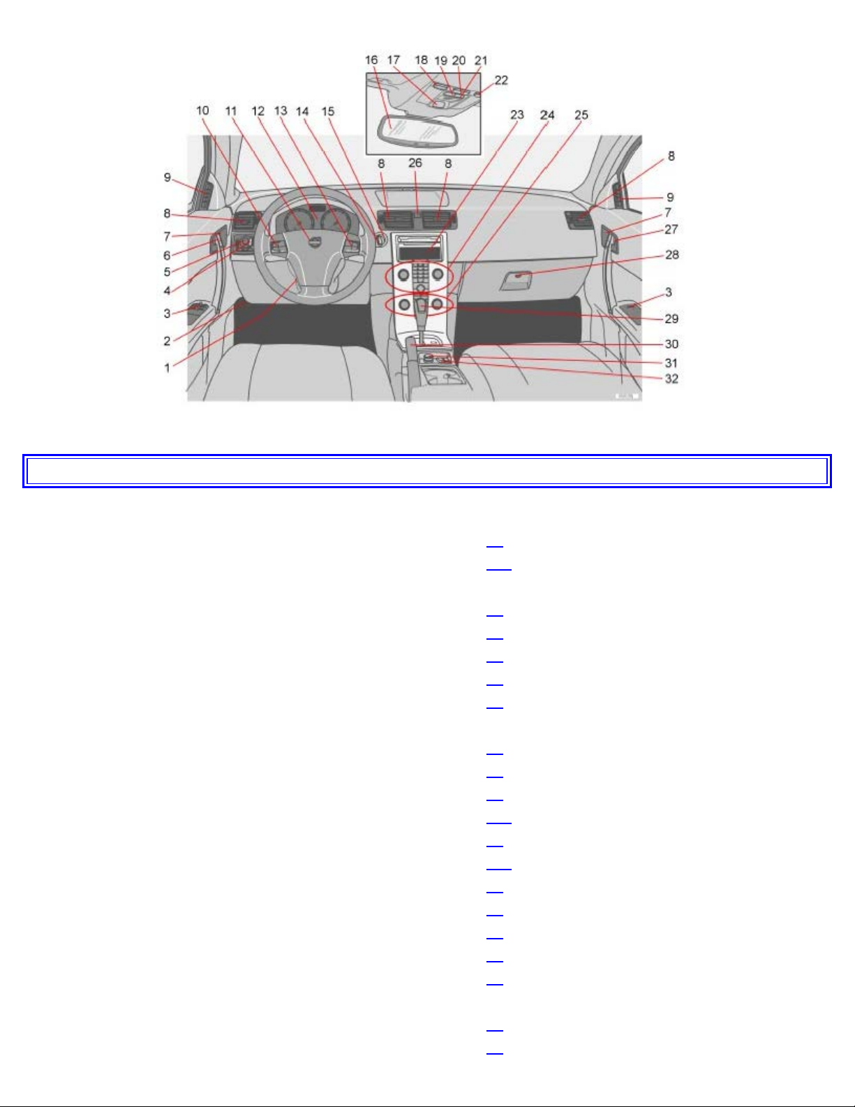
23. Display for climate control, personal settings, and audio system 51
Page
1. Steering wheel adjustment 46
2. Hood opener 157
3. Controls in driver's door (see inset illustration below)
4. Left steering wheel lever 40
5. Lighting panel, fuel filler door opener 38
6. Door open handle, and locking button 93
7. Lock indicator light 93
8. Climate system air vent 59
9. Side window air vent
10. Cruise control 42
11. Horn, airbag 14
12. Main instrument panel 32
13. Audio controls 176
14. Right steering wheel lever 44
15. Ignition switch 104
16. Rear-view mirror and optional compass 49
17. Seat belt reminder 13
18. Driver's side reading light 77
19. Movement detector (option), alarm sensor 95
20. Courtesy lighting switch 77
21. Position for accessory switch
22. Passenger's side reading light 77
Page 7

24. Controls for personal settings and audio system 51 / 176
25. Controls for climate system 60
26. Hazard warning flashers 46
27. Door open handle, and locking button 93
28. Glove compartment 90
29. Gear selector, manual/ 107
29. Gear selector, automatic 108
30. Parking brake 47
31. 12-volt socket 47
32. Switches for raising/lowering the power retractable hard top 72
Page
1. All windows up/down 48
2. Power windows 48
3. Door mirror button, driver's side 50
4. Door mirror adjustment control 50
5. Door mirror button, passenger's side 50
Contents | Top of Page
Page 8
2 0 0 6
VOLVO
C70
Chapter 2 - Safety
pg. 9 Safety
Occupant safety 10
Seat belts 11
Supplemental Restraint System (SRS) 14
Front airbags 15
Occupant Weight Sensor - disabling the passenger's side front airbag 18
Side impact protection (SIPS) airbags 21
Door Mounted Inflatable Curtain (DMIC) 22
Whiplash Protection System (WHIPS) 23
Roll-over Protection system (ROPS) 25
Collision status 26
Inspecting SRS system components 27
Child safety 28
pg. 10 Safety
Occupant safety
Volvo's concern for safety
Safety is Volvo's cornerstone. Our concern dates back to 1927 when the first Volvo rolled off the production line.
Three-point seat belts (a Volvo invention), safety cages, and energy-absorbing impact zones were designed into Volvo
cars long before it was fashionable or required by government regulation.
We will not compromise our commitment to safety. We continue to seek out new safety features and to refine those
already in our cars. You can help. We would appreciate hearing your suggestions about improving automobile safety.
We also want to know if you ever have a safety concern with your car. Call us in the U.S. at: 1-800-458-1552 or in
Canada at: 1-800-663-8255.
Occupant safety reminders
How safely you drive doesn't depend on how old you are but rather on:
How well you see.
Your ability to concentrate.
How quickly you make decisions under stress to avoid an accident.
The following suggestions are intended to help you cope with the ever changing traffic environment.
Never drink and drive.
If you are taking any medication, consult your physician about its potential effects on your driving abilities.
Page 9
Take a driver-retraining course.
Have your eyes checked regularly.
Keep your windshield and headlights clean.
Replace wiper blades when they start to leave streaks.
Take into account the traffic, road, and weather conditions, particularly with regard to stopping distance.
Reporting safety defects in the U.S.
If you believe that your vehicle has a defect which could cause a crash or could cause injury or death, you should
immediately inform the National Highway Traffic Safety Administration (NHTSA) in addition to notifying Volvo Cars
of North America. If NHTSA receives similar complaints, it may open an investigation, and if it finds that a safety
defect exists in a group of vehicles, it may order a recall and remedy campaign. However, NHTSA cannot become
involved in individual problems between you, your retailer, or Volvo Cars of North America.
To contact NHTSA, you may either call the Auto Safety Hotline toll-free at 1-888-327-4236 (TTY: 1-800-424-9153)
or write to: NHTSA, U.S. Department of Transportation, Washington D.C. 20590. You can also obtain other
information about motor vehicle safety from the Hotline.
Volvo strongly recommends that if your vehicle is covered under a service campaign, safety or emission recall or
similar action, it should be completed as soon as possible. Please check with your local retailer or Volvo Cars of North
America, LLC if your vehicle is covered under these conditions.
NHTSA can be reached at:
Internet:
http://www.nhtsa.gov
Telephone:
1-888-DASH-2-DOT (1-888-327-4236).
pg. 11 Safety
Seat belts
Using seat belts
Volvo, the inventor of the three-point seat belt, urges you and all occupants of your vehicle to wear seat belts and
ensure that children are properly restrained, using an infant, car, or booster seat determined by age, weight and height.
Volvo also believes no child should sit in the front seat of a vehicle.
Most states and provinces make it mandatory for occupants of a vehicle to use seat belts.
Seat belt tensioners
The front and rear seat belts are equipped with tensioners that reduce slack in the belts. These tensioners are triggered
in situations where the airbags deploy. The front seat belts also include a tension reducing device which, in the event
of a collision, limits the peak forces exerted by the seat belt on the occupant.
Page 10
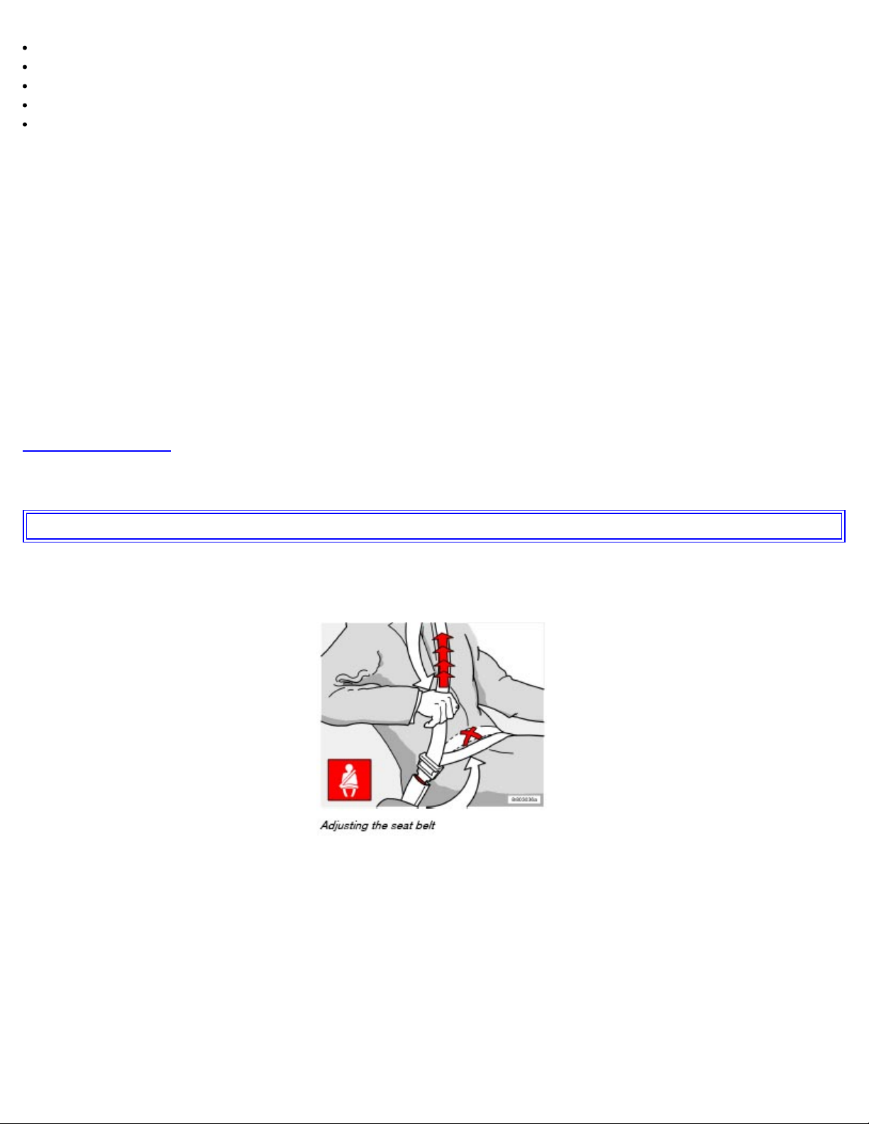
Buckling a seat belt
Pull the belt out far enough to insert the latch plate into the receptacle until a distinct click is heard. The seat belt
retractor is normally "unlocked" and you can move freely, provided that the shoulder belt is not pulled out too far. The
retractor will lock up as follows:
if the belt is pulled out rapidly
during braking and acceleration
if the vehicle is leaning excessively
when driving in turns
When wearing the seat belt remember:
The belt should not be twisted or turned.
The lap section of the belt must be positioned low on the hips (not pressing against the abdomen).
Make sure that the shoulder belt is rolled up into its retractor and that the shoulder and lap belts are taut.
Unbuckling the seat belt
To remove the seat belt, press the red section on the seat belt receptacle. Before exiting the vehicle, check that the
seat belt retracts fully after being unbuckled. If necessary, guide the belt back into the retractor slot.
WARNING!
Never use a seat belt for more than one occupant. Never wear the shoulder portion of the belt under the arm, behind
the back or otherwise out of position. Such use could cause injury in the event of an accident. As seat belts lose
much of their strength when exposed to violent stretching, they should be replaced after any collision, even if they
appear to be undamaged.
pg. 12 Safety
Seat belts
WARNING!
Never repair the belt yourself; have this work done by a trained and qualified Volvo service technician only.
Any device used to induce slack into the shoulder belt portion of the three-point belt system will have a
detrimental effect on the amount of protection available to you in the event of a collision.
Page 11
The seat back should not be tilted too far back. The shoulder belt must be taut in order to function properly.
Do not use child safety seats or child booster cushions/backrests in the front passenger's seat. We also recommend
that children who have outgrown these devices sit in the rear seat with the seat belt properly fastened.
Seat belt use during pregnancy
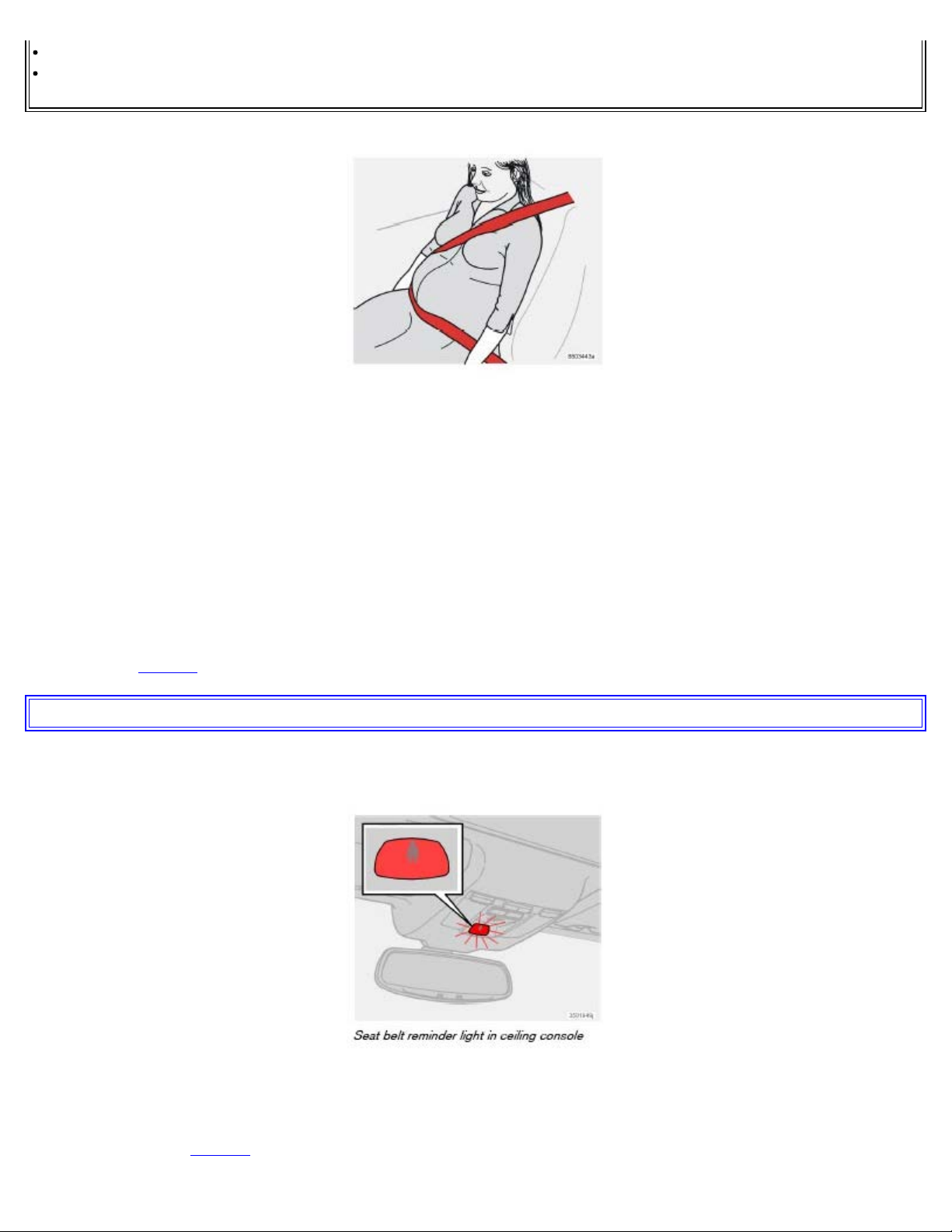
The seat belt should always be worn during pregnancy. But it is crucial that it be worn in the correct way. The diagonal
section should wrap over the shoulder then be routed between the breasts and to the side of the belly. The lap section
should lay flat over the thighs and as low as possible under the belly. It must never be allowed to ride upward. Remove
all slack from the belt and insure that it fits close to the body without any twists.
As a pregnancy progresses, pregnant drivers should adjust their seats and steering wheel such that they can easily
maintain control of the vehicle as they drive (which means they must be able to easily operate the foot pedals and
steering wheel). Within this context, they should strive to position the seat with as large a distance as possible between
their belly and the steering wheel.
Child seats
Please refer to page 30 for information on securing child seats with the seat belts.
pg. 13 Safety
Seat belts
Seat belt reminder
The seat belt reminder consists of an audible signal, an indicator light above the rearview mirror, and a symbol in the
instrument panel (see page 35 ) that alert the driver and front seat passenger if their seat belts are not fastened.
Page 12
NOTE: The function is active for a total of 6 minutes from the time the ignition is switched on.
During the first minute:
The seat belt reminder function only reacts if the driver has not fastened his/her seat belt.
The indicator light above the mirror and the symbol in the instrument panel will light up and stay lit until the seat
belt has been fastened.
A chime will sound for 6 seconds. The frequency of the chiming increases with the speed of the car.
After one minute has elapsed:
The seat belt reminder reacts if the driver and/or the front seat passenger have not fastened their seat belts.
The indicator light above the mirror and the symbol in the instrument panel will light up and stay lit until the seat
belt(s) have been fastened, or until the remaining 5 minutes of the 6-minute cycle have elapsed.
The chime will sound for 6 seconds, at 30-second intervals. The frequency of the chiming increases with the speed
of the car. After 6 minutes, the chime will no longer sound and the indicator lights will go out.
Seat belt maintenance
Check periodically that the seat belts are in good condition. Use water and a mild detergent for cleaning. Check seat
belt mechanism function as follows: attach the seat belt and pull rapidly on the strap.
pg. 14 Safety
Supplemental Restraint System (SRS)
Supplemental Restraint System
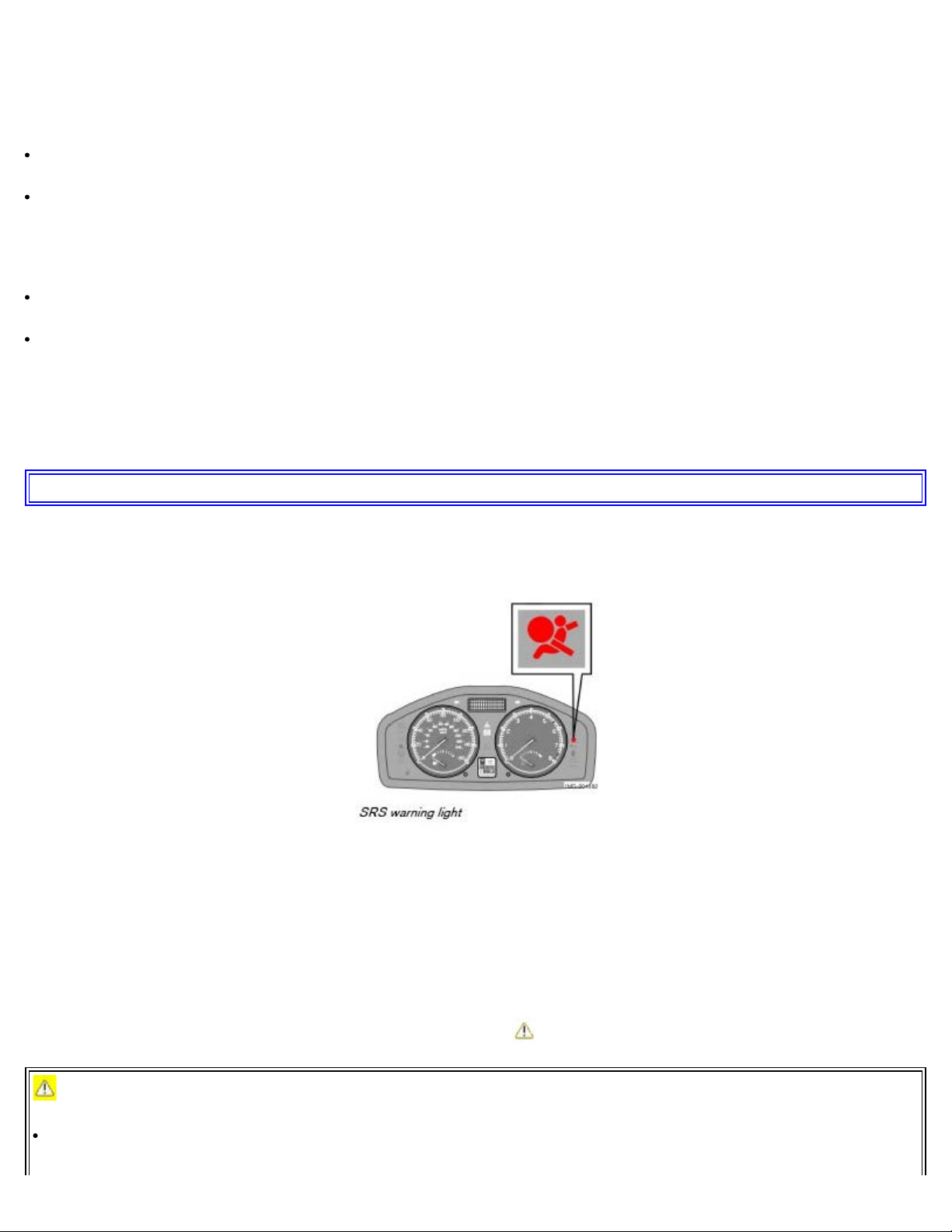
As an enhancement to the three-point seat belts, your Volvo is equipped with a Supplemental Restraint System (SRS).
Volvo's SRS consists of seat belt tensioners, front airbags, side impact airbags, the occupant weight sensor, and
inflatable curtains. All of these systems are monitored by the SRS control module. An SRS warning light in the
instrument panel (see the illustration above) illuminates when the ignition key is turned to position I, II, or III, and will
normally go out after approximately 7 seconds if no faults are detected in the system.
Where applicable, a text message will also be displayed when the SRS warning light illuminates. If this warning
symbol is not functioning properly, the general warning symbol illuminates and a text message will be displayed.
WARNING!
If the SRS warning light stays on after the engine has started or if it illuminates while you are driving, have the
vehicle inspected by a trained and qualified Volvo service technician as soon as possible.
Page 13
Never try to repair any component or part of the SRS yourself. Any interference in the system could cause
malfunction and serious injury. All work on these systems should be performed by a trained and qualified Volvo
service technician.
WARNING!
If your vehicle has been subjected to flood conditions (e.g. soaked carpeting/ standing water on the floor of the
vehicle) or if your vehicle has become flood-damaged in any way, do not attempt to start the vehicle or put the key
in the ignition before disconnecting the battery (see below). This may cause airbag deployment which could result in
personal injury. Have the vehicle towed to a trained and qualified Volvo service technician for repairs.
Automatic transmission:
Before attempting to tow the vehicle, use the following procedure to override the shiftlock system to move the gear
selector to the neutral position:
Switch off the ignition for at least 10 minutes and disconnect the battery
Wait at least one minute.
Insert the key in the ignition and turn it to position II.
Press firmly on the brake pedal.
Move the gear selector from (P)ark to the (N)eutral position. See page 110 for information on manually overriding
the shiftlock system.
pg. 15 Safety
Front airbags
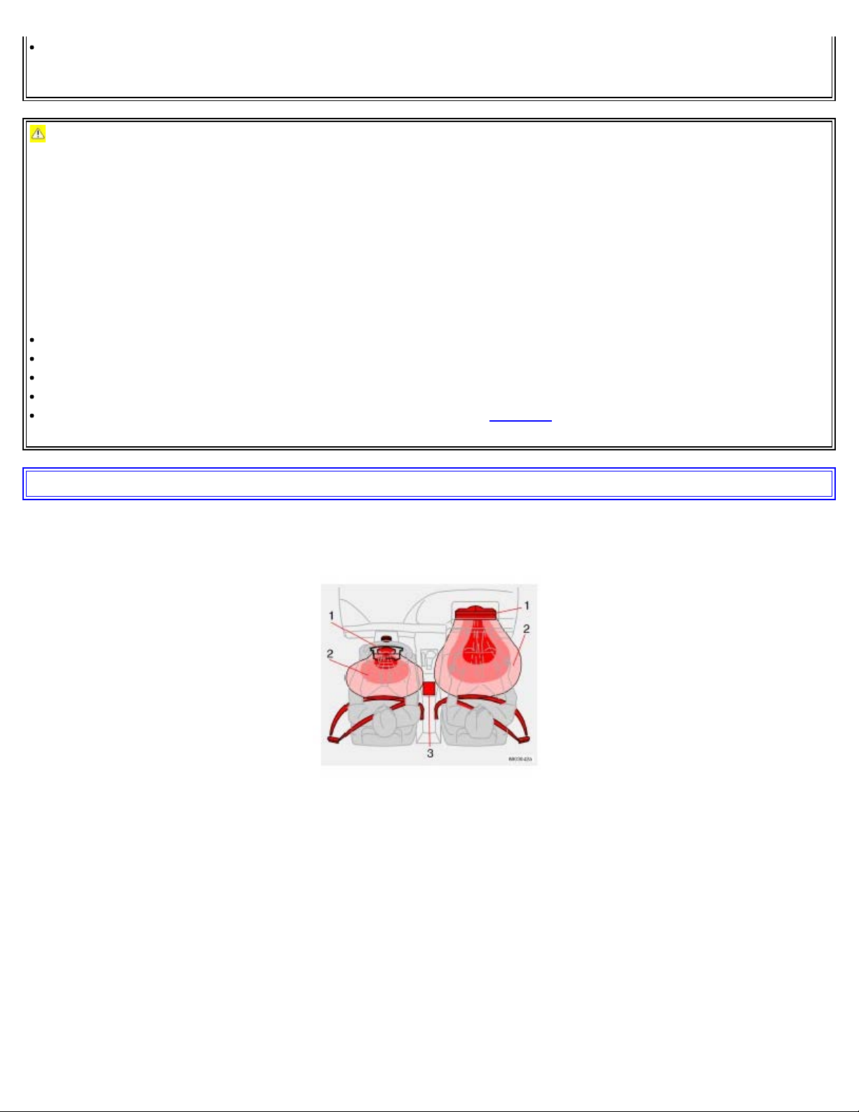
The front airbag system
The front airbags supplement the three-point seat belts. For these airbags to provide the protection intended, seat belts
must be worn at all times.
The front airbag system includes gas generators (1) surrounded by the airbags (2) and a deceleration sensor (3) that
activates the gas generators, causing the airbags to be inflated with nitrogen gas.
Page 14
As the movement of the seats' occupants compresses the airbags, some of the gas is expelled at a controlled rate to
provide better cushioning. Both seat belt tensioners also deploy, minimizing seat belt slack. The entire process,
including inflation and deflation of the airbags, takes approximately one fifth of a second.
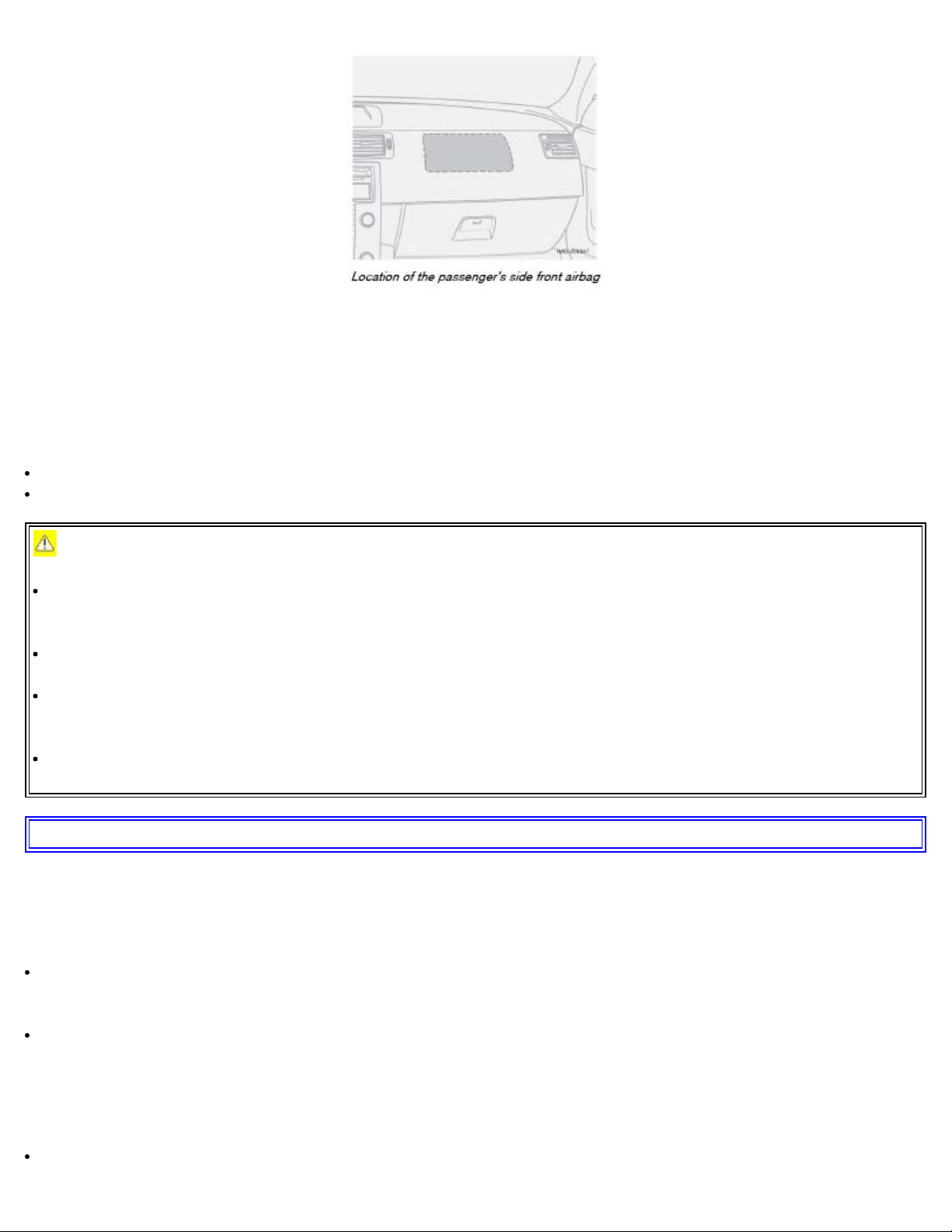
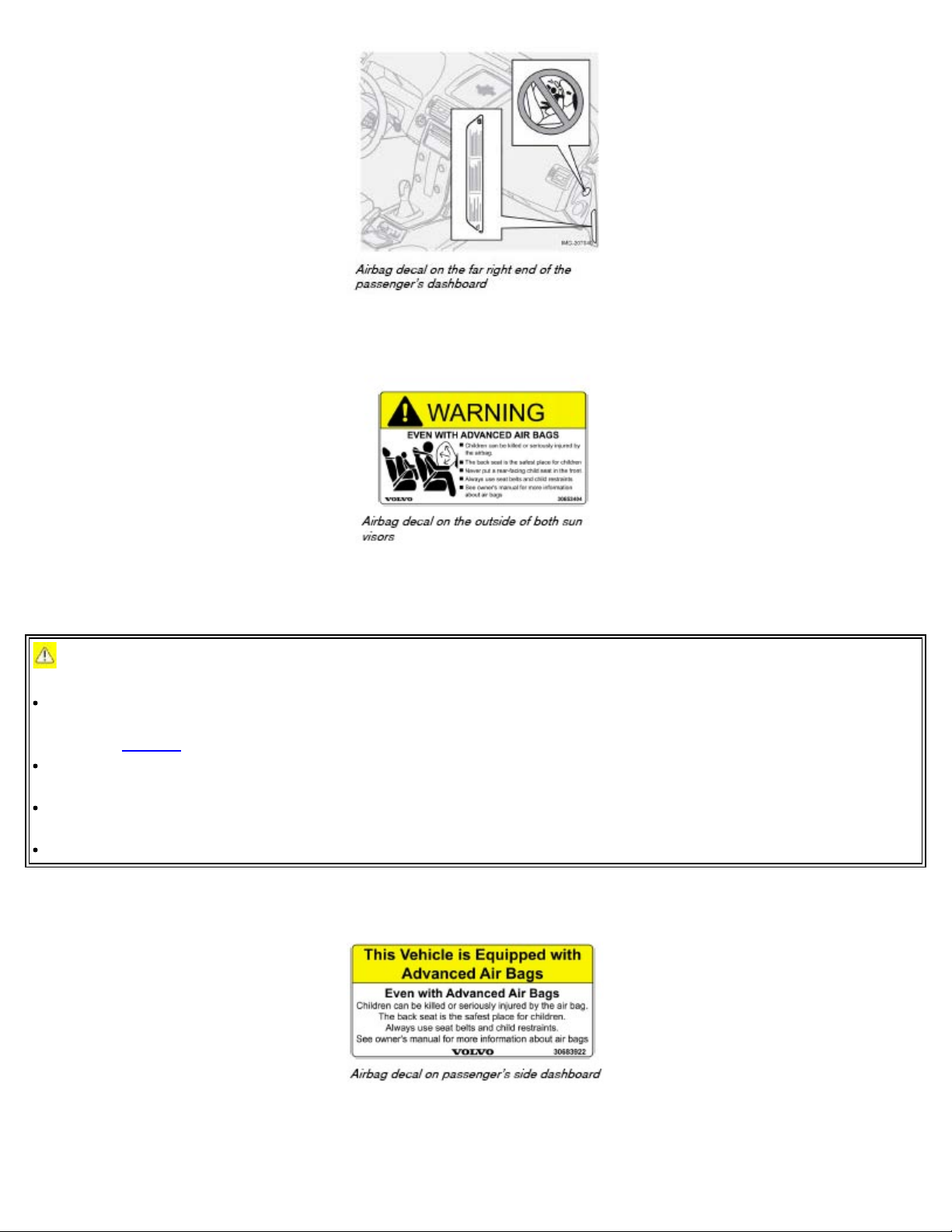
The location of the front airbags is indicated by "SRS AIRBAG" embossed on the steering wheel pad and above the
glove compartment, and by decals on both sun visors and on the front and far right side of the dash.
The driver's side front airbag is folded and located in the steering wheel hub.
The passenger's side front airbag is folded behind a panel located above the glove compartment.
WARNING!
The airbags in the vehicle are designed to be a SUPPLEMENT to-not a replacement for-the three-point seat belts.
For maximum protection, wear seat belts at all times. Be aware that no system can prevent all possible injuries that
may occur in an accident.
Never drive a vehicle with a steering wheel-mounted airbag with your hands on the steering wheel pad/airbag
housing.
The front airbags are designed to help prevent serious injury. Deployment occurs very quickly and with
considerable force. During normal deployment and depending on variables such as seating position, one may
experience abrasions, bruises, swellings, or other injuries as a result from deployment of one or both of the airbags.
When installing any accessory equipment, make sure that the front airbag system is not damaged. Any interference
in the system could cause malfunction.
pg. 16 Safety
Front airbags
Front airbag deployment
The front airbags are designed to deploy during certain frontal or front-angular collisions, impacts, or decelerations,
depending on the crash severity, angle, speed and object impacted. The airbags may also deploy in certain non-frontal
collisions where rapid deceleration occurs.
The SRS sensors, which trigger the front airbags, are designed to react to both the impact of the collision and the
inertial forces generated by it, and to determine if the intensity of the collision is sufficient for the seat belt tensioners
and/or airbags to be deployed.
However, not all frontal collisions activate the front airbags.
If the collision involves a nonrigid object (e.g., a snow drift or bush), or a rigid, fixed object at a low speed, the
Page 15

front airbags will not necessarily deploy.
Front airbags do not normally deploy in a side impact collision, in a collision from the rear or in a rollover situation.
The amount of damage to the bodywork does not reliably indicate if the airbags should have deployed or not.
NOTE:
Deployment of front airbags occurs only one time during an accident. In a collision where deployment occurs, the
airbags and seat belt tensioners activate. Some noise occurs and a small amount of powder is released. The release of
the powder may appear as smoke-like matter. This is a normal characteristic and does not indicate fire.
Volvo's dual-threshold, dual-stage front airbags use special sensors that are integrated with the front seat buckles.
The point at which the airbag deploys is determined by whether or not the seat belt is being used, as well as the
severity of the collision.
Collisions can occur where only one of the airbags deploys. If the impact is less severe, but severe enough to present
a clear injury risk, the dual-stage airbags are triggered at 70% of their total capacity. If the impact is more severe, the
dual-stage airbags are triggered at full capacity.
Should you have questions about any component in the SRS system, please contact a trained and qualified Volvo
service technician or Volvo Customer Support:
In the USA
Volvo Cars of North America
Customer Care Center
P.O. Box 914 Rockleigh, New Jersey 07647-0914
1-800-458-1552
http://www.volvocars.us
In Canada
Volvo Cars of Canada Ltd.
National Customer Service
175 Gordon Baker Road
North York, Ontario M2H 2N7
1-800-663-8255
http://www.volvocanada.com
WARNING!
Do not use child safety seats or child booster cushions/backrests in the front passenger's seat. We also recommend
that occupants under 4 feet 7 inches (140 cm) in height who have outgrown these devices sit in the rear seat with the
seat belt fastened(a).
Never drive with the airbags deployed. The fact that they hang out can impair the steering of your vehicle. Other
safety systems can also be damaged.
The smoke and dust formed when the airbags are deployed can cause skin and eye irritation in the event of
prolonged exposure.
a. See also the Occupant Weight Sensor information on page 18
.
pg. 17 Safety
Page 16
WARNING!
Children must never be allowed in the front passenger's seat. Volvo recommends that ALL occupants (adults and
children) shorter than 4 feet 7 inches (140 cm) be seated in the back seat of any vehicle with a passenger-side front
airbag. See page 30 for guidelines.
Occupants in the front passenger's seat must never sit on the edge of the seat, sit leaning toward the instrument
panel or otherwise sit out of position.
The occupant's back must be as upright as comfort allows and be against the seat back with the seat belt properly
fastened.
Feet must be on the floor, e.g., not on the dash, seat or out of the window.
Page 17
WARNING!
No objects or accessory equipment, e.g. dashboard covers, may be placed on, attached to, or installed near the air
bag hatch (the area above the glove compartment) or the area affected by airbag deployment (see the illustration on
page 14).
There should be no loose articles, e.g. coffee cups, on the floor, seat, or dashboard area.
Never try to open the airbag cover on the steering wheel or the passenger's side dashboard. This should only be
done by a trained and qualified Volvo service technician.
Failure to follow these instructions can result in injury to the vehicle occupants.
pg. 18 Safety
Occupant Weight Sensor - disabling the passenger's side front airbag
Disabling the passenger's side front airbag
Volvo recommends that ALL occupants (adults and children) shorter than 4 feet 7 inches (140 cm) be seated in the
back seat of any vehicle with a front passenger side airbag, and be properly restrained for their size and weight. See
also the child safety recommendations on page 30.
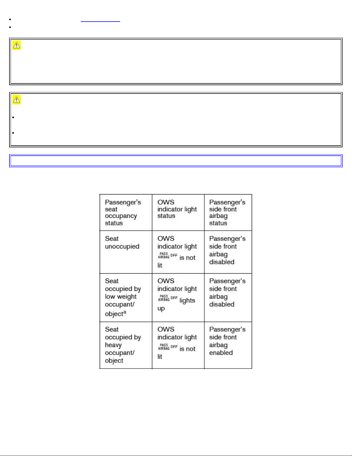
The passenger's side front airbag is automatically enabled/disabled by the Occupant Weight Sensor (OWS), a system
that monitors the weight of the person or object in the front passenger's seat. The system consists of a silicone-filled
bag located under the padding in the front passenger's seat cushion, a control module located under this seat, and a seat
belt tension sensor, located on the outboard side of the seat.
The OWS system continuously monitors the pressure on the front passenger's seat cushion and the tension applied to
the seat belt. Based on this data, OWS assesses the weight of the occupant or object in the front passenger's seat. This
information is transmitted to the SRS system control module, which enables or disables the passenger's side front
airbag accordingly, as indicated in the table on the following page.
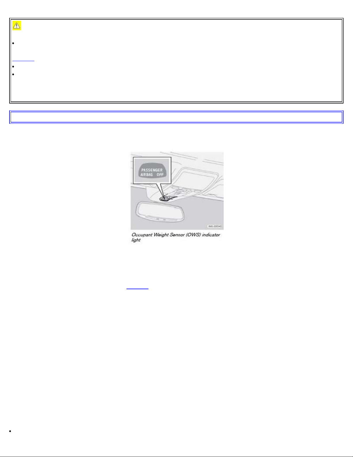
If the system is functioning normally, the status of the front passenger's side airbag (enabled/disabled) will be shown
by the OWS indicator light as explained in the table on the following page. The OWS indicator light is separate and in
addition to the SRS warning light in the instrument panel.
NOTE: When the ignition is switched on, the OWS indicator light will go on for up to 10 seconds while the system
performs a self-diagnostic test. The light will then go out unless the seat is occupied by a low weight occupant/object.
However, if a fault is detected in the system:
The OWS indicator light will stay on
Page 18
The SRS warning light (see page 14) will come on and stay on
The message PASS. AIRBAG OFF SERVICE URGENT will be displayed in the information display.
WARNING!
If a fault in the system is detected and indicated as explained on the preceding page, be aware that the passenger's
side front airbag will not deploy in the event of a collision. In this case, the SRS system and Occupant Weight
Sensor should be inspected by a trained and qualified Volvo service technician as soon as possible.
WARNING!
Never try to open, remove, or repair any components in the OWS system. This could result in system malfunction.
Maintenance or repairs should only be carried out by an a trained and qualified Volvo service technician.
The front passenger's seat should not be modified in any way. This could reduce pressure on the seat cushion,
which might interfere with the OWS system's function.
pg. 19 Safety
Occupant Weight Sensor - disabling the passenger's side front airbag
a. Volvo recommends that children always be properly restrained in appropriate child restraints in the rear seats. In rare
situations when the seat belt is not latched, some child restraint systems may not be detected by the OWS because there
is very little weight on the vehicle seat cushion. In these cases the airbag may be turned off but the "passenger airbag
off" indicator would not be lit. DO NOT assume the front passenger airbag is turned off unless the indicator is lit.
Make sure the child restraint is properly belted and that the indicator is lit, or move the child restraint to the rear seat.
Page 19

Modifications
If you are considering modifying your vehicle in any way to accommodate a disability, for example by altering or
adapting the driver's or front passenger's seat(s) and/or airbag systems, please contact Volvo at:
In the USA
Volvo Cars of North America
Customer Care Center
P.O. Box 914 Rockleigh, New Jersey 07647-0914
1-800-458-1552
In Canada
Volvo Cars of Canada Ltd.
National Customer Service
175 Gordon Baker Road
North York, Ontario M2H 2N7
1-800-663-8255
pg. 20 Safety
Occupant Weight Sensor - disabling the passenger's side front airbag
WARNING!
No objects that add to the total weight on the seat should be placed on the front passenger's seat. If a child is seated
in the front passenger's seat with any additional weight, this extra weight could cause the OWS system to enable the
airbag, which might cause it to deploy in the event of a collision, thereby injuring the child.
The seat belt should never be wrapped around an object on the front passenger's seat. This could interfere with the
OWS system's function.
The front passenger's seat belt should never be used in a way that exerts more pressure on the passenger than
normal. This could increase the pressure exerted on the weight sensor by a child, and could result in the airbag being
enabled, which might cause it to deploy in the event of a collision, thereby injuring the child.
WARNING!
Keep the following points in mind with respect to the OWS system. Failure to follow these instructions could
adversely affect the system's function and result in serious injury to the occupant of the front passenger's seat:
The full weight of the front seat passenger should always be on the seat cushion. The passenger should never lift
him/herself off the seat cushion using the armrest in the door or the center console, by pressing the feet on the floor,
by sitting on the edge of the seat cushion, or by pressing against the backrest in a way that reduces pressure on the
seat cushion. This could cause OWS to disable the front, passenger's side airbag.
Do not place any type of object on the front passenger's seat in such a way that jamming, pressing, or squeezing
occurs between the object and the front seat, other than as a direct result of the correct use of the ALR/ELR seat belt
(see page 30).
No objects should be placed under the front passenger's seat. This could interfere with the OWS system's function.
pg. 21 Safety
Side impact protection (SIPS) airbags
Page 20
Side impact airbags - front seats only
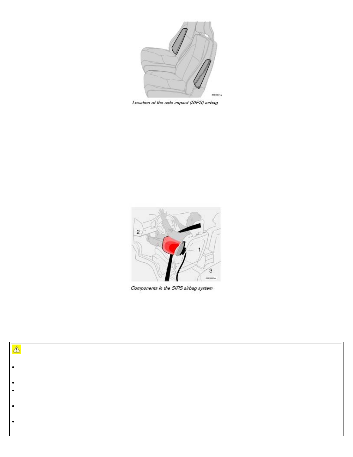
As an enhancement to the structural side impact protection built into your car, the car is also equipped with Side
Impact Protection System (SIPS) airbags.
The SIPS airbag system is designed to help increase occupant protection in the event of certain side impact collisions.
The SIPS airbags are designed to deploy only during certain side-impact collisions, depending on the crash severity,
angle, speed and point of impact.
NOTE: SIPS airbag deployment (one airbag) occurs only on the side of the vehicle affected by the impact. The airbags
are not designed to deploy in all side impact situations.
Components in the SIPS airbag system
This SIPS airbag system consists of a gas generator (1), the side airbag modules built into the outboard sides of both
front seat backrests (2), and electronic sensors/wiring (3).
WARNING!
The SIPS airbag system is a supplement to the structural Side Impact Protection System and the three-point seat
belt system. It is not designed to deploy during collisions from the front or rear of the car or in rollover situations.
The use of seat covers on the front seats may impede SIPS airbag deployment.
No objects, accessory equipment or stickers may be placed on, attached to or installed near the SIPS airbag system
or in the area affected by SIPS airbag deployment.
Never try to open or repair any components of the SIPS airbag system. This should be done only by a trained and
qualified Volvo service technician.
In order for the SIPS airbag to provide its best protection, both front seat occupants should sit in an upright
position with the seat belt properly fastened.
Page 21
Failure to follow these instructions can result in injury to the occupants of the vehicle in the event of an accident.
pg. 22 Safety
Door Mounted Inflatable Curtain (DMIC)
The Door Mounted Inflatable Curtain system
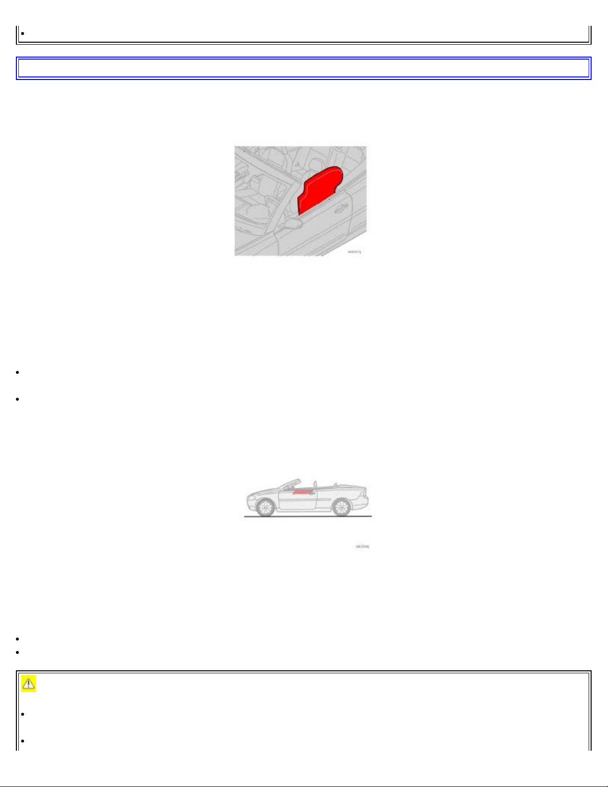
The DMIC is a supplement to the structural side impact protection. These inflatable curtains are concealed in the upper
section of the driver and passenger doors.
The Inflatable Curtain (DMIC) and the Side Impact Airbag System (SIPS-bag) will both deploy in certain side
impacts.
In certain situations in which there is a roll-over risk, only the inflatable curtain (DMIC) may deploy.
NOTE:
DMIC deployment can occur regardless of whether the power retractable hard top is up or down.
If the inflatable curtain deploys, it remains inflated for approximately 5 seconds.
WARNING!
The DMIC system is a supplement to the Side Impact Protection System. It is not designed to deploy during
collisions from the front or rear of the car. It only provides protection for the occupants of the front seats.
Never install or mount any equipment on the insides of the doors, door pillars, or side panels. This could impede
Page 22
the function of the DMIC system.
Never try to open or repair any components of the DMIC system. This should be done only by a trained and
qualified Volvo service technician.
WARNING!
In order for the DMIC to provide its best protection, both front seat occupants should sit in an upright position with
the seat belt properly fastened; adults using the seat belt and children using the proper child restraint system. Only
adults should sit in the front seats. Children must never be allowed in the front passenger seat. See page 30 for
guidelines. Failure to follow these instructions can result in injury to the vehicle occupants in an accident.
pg. 23 Safety
Whiplash Protection System (WHIPS)
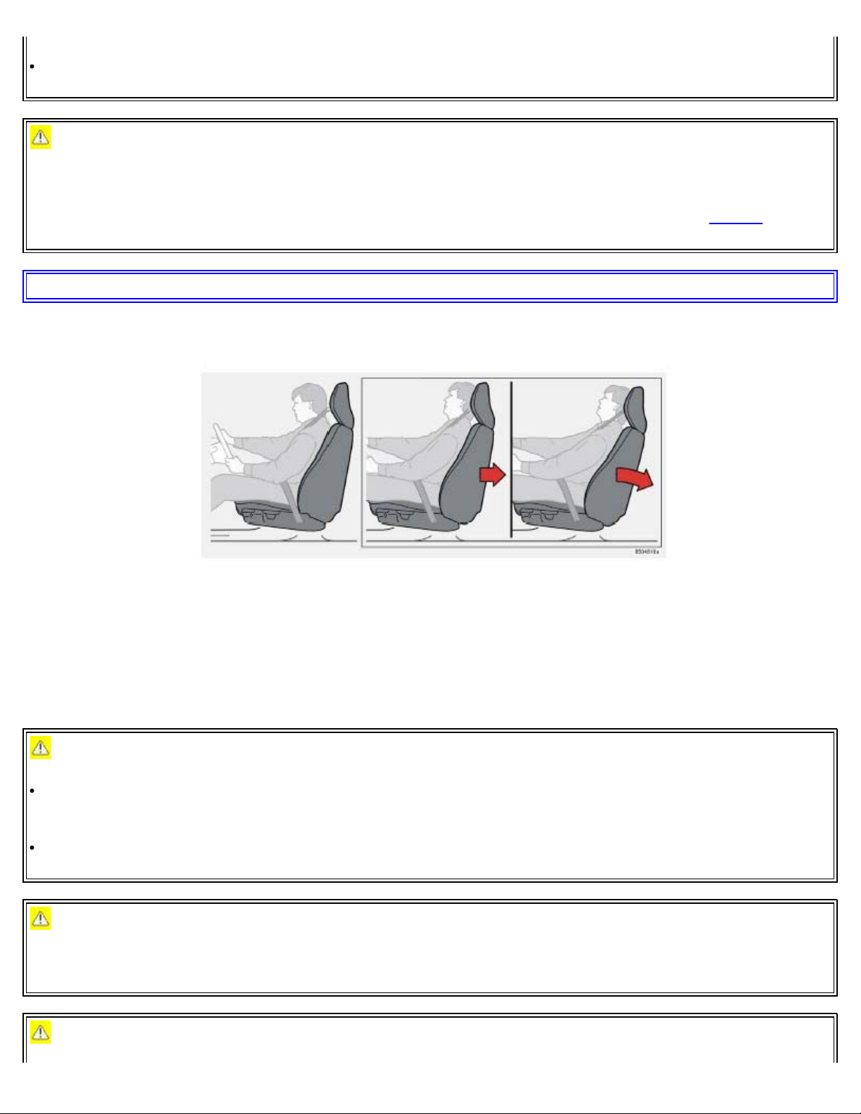
Whiplash Protection System (WHIPS) - front seats only
The WHIPS system consists of specially designed hinges and brackets on the front seat backrests designed to help
absorb some of the energy generated in a collision from the rear (when the vehicle is "rear-ended"). In the event of a
collision of this type, the hinges and brackets of the front seat backrests are designed to change position slightly to
allow the backrest/head restraint to help support the occupant's head before moving slightly rearward. This movement
helps absorb some of the forces that could result in whiplash.
WARNING!
The WHIPS system is designed to supplement the other safety systems in your car. For this system to function
properly, the three-point seat belt must be worn. Please be aware that no system can prevent all possible injuries that
may occur in an accident.
The WHIPS system is designed to function in certain collisions from the rear, depending on the crash severity,
angle and speed.
WARNING!
Occupants in the front seats must never sit out of position. The occupant's back must be as upright as comfort allows
and be against the seat back with the seat belt properly fastened.
WARNING!
Page 23
If your car has been involved in a rearend collision, the front seat backrests must be inspected by a trained and
qualified Volvo service technician, even if the seats appear to be undamaged. Certain components in the WHIPS
system may need to be replaced.
Do not attempt to service any component in the WHIPS system yourself.
pg. 24 Safety
Whiplash Protection System (WHIPS)
WARNING!
Boxes, suitcases, etc. wedged behind the front seats could impede the function of the WHIPS system.
pg. 25 Safety
Roll- over Protection system (ROPS)
Roll-over Protection system (ROPS)
The ROPS system consists of two roll bars located behind the rear seat head restraints, and a sensor that monitors the
roll or pitch angle of the car.
If the car rolls or pitches beyond a preset angle, the roll bars are automatically deployed (raised).
Page 24

NOTE:
The ROPS system is designed to function regardless of whether the power retractable hard top is up or down. By
design, the tops of the roll bars are equipped with a point in order to pierce the rear window if the top is up.
If ROPS has deployed, the system should be inspected and repaired if necessary by a trained and qualified Volvo
service technician.
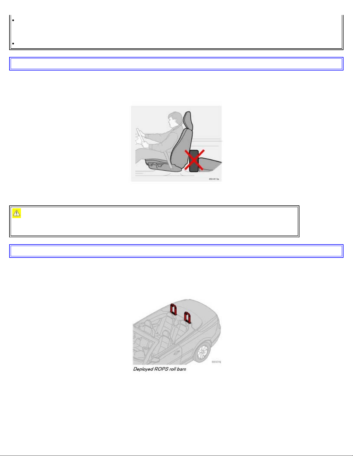
WARNING!
The rear seat of the Volvo C70 is intended for two occupants, and only two rear seat belts are provided. The center
section of the seat should never be used to seat a passenger.
No objects should be placed over the roll bars or behind the rear seat head restraints.
All repairs or maintenance to the ROPS system should only be performed by a trained Volvo service technician.
pg. 26 Safety
Collision status
Driving after a collision
If the car has been involved in a collision, the text CRASH STATUS SEE MANUAL may appear in the information
display. This indicates that the car's functionality has been reduced.
NOTE: This text can only be shown if the display is undamaged and the car's electrical system is intact.
COLLISION STATUS is a feature that is triggered if one or more of the safety systems (e.g. front or side airbags, an
inflatable curtain, or one or more of the seat belt tensioners) has deployed. The collision may have damaged an
important function in the car, such as the fuel lines, sensors for one of the safety systems, the brake system, etc.
WARNING!
Never attempt to repair the car yourself or to reset the electrical system after the car has displayed CRASH
STATUS SEE MANUAL. This could result in injury or improper system function.
Restoring the car to normal operating status should only be done by a trained and qualified Volvo service
technician.
After CRASH STATUS SEE MANUAL has been displayed, if you detect the odor of fuel vapor, or see any signs
of fuel leakage, do not attempt to start the car. Leave the car immediately.
Page 25

Attempting to start the car
If damage to the car is minor and there is no fuel leakage, you may attempt to start the car. To do so:
Remove the ignition key.
Reinsert the key in the ignition switch. The car will then attempt to reset COLLISION STATUS to normal status.
Try to start the car.
Moving the car
If the electrical system is able to reset system status to normal (CRASH STATUS SEE MANUAL will no longer be
shown in the display), the car may be moved carefully from its present position, if for example, it is blocking traffic. It
should, however, not be moved farther than is absolutely necessary.
WARNING!
Even if the car appears to be drivable after COLLISION STATUS has been set, it should not be driven or towed
(pulled by another vehicle). There may be concealed damage that could make it difficult or impossible to control.
The car should be transported on a flatbed tow truck to a trained and qualified Volvo service technician for
inspection/repairs.
pg. 27 Safety
Inspecting SRS system components
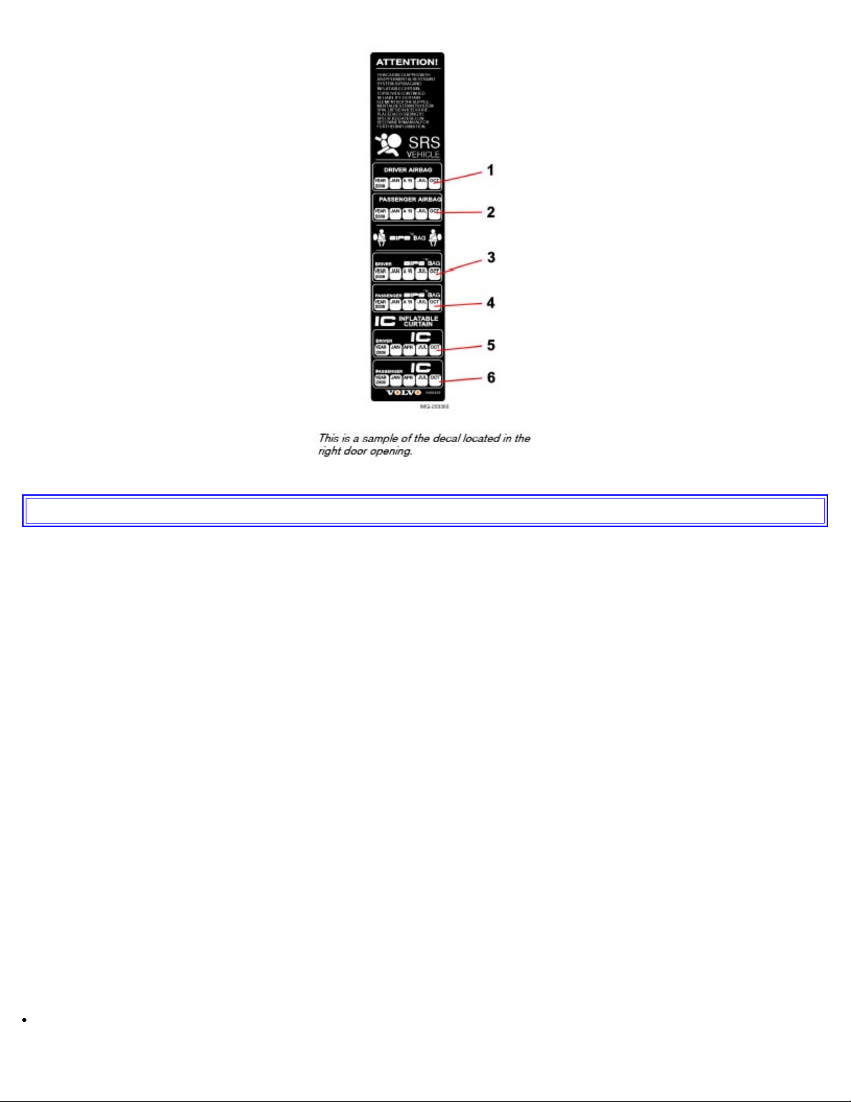
Inspection date
1. Driver's side airbag
2. Passenger's side airbag
3. Side airbag on the driver's side
4. Side airbag on the passenger's side
5. Driver's side inflatable curtain
6. Passenger's side inflatable curtain
WARNING!
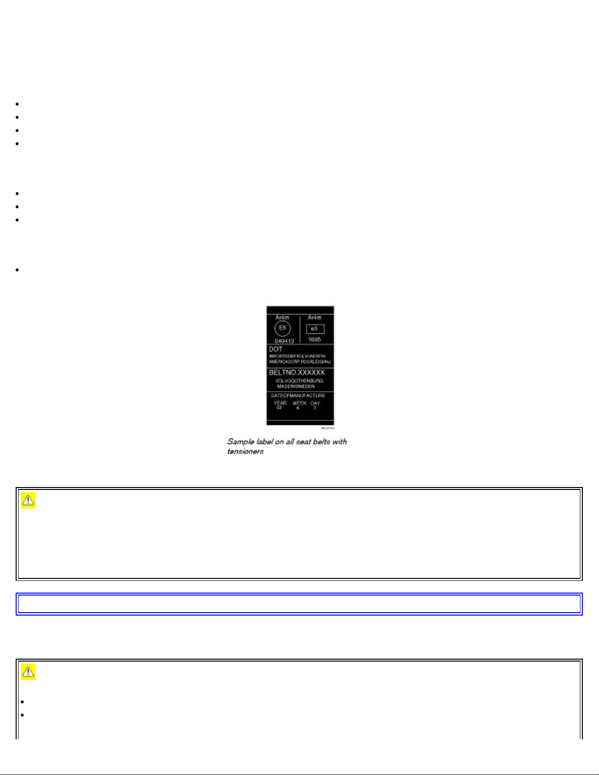
There is no owner maintenance that can be performed on the SRS system. The month and year shown on the decal to
the right (located on door pillar) indicate when you should contact your Volvo retailer for specific servicing or
replacement of airbag system components. This service must be performed by a trained and qualified Volvo service
technician.
Page 26
pg. 28 Safety
Child safety
Children should be seated safely
Volvo recommends the proper use of restraint systems for all occupants including children. Remember that, regardless
of age and size, a child should always be properly restrained in a car.
Your car is also equipped with ISOFIX/ LATCH attachments, which make it more convenient to install child seats.
Some restraint systems for children are designed to be secured in the vehicle by lap belts or the lap portion of a lap-
shoulder belt. Such child restraint systems can help protect children in cars in the event of an accident only if they are
used properly. However, children could be endangered in a crash if the child restraints are not properly secured in the
vehicle. Failure to follow the installation instructions for your child restraint can result in your child striking the
vehicle's interior in a sudden stop.
Holding a child in your arms is NOT a suitable substitute for a child restraint system. In an accident, a child held in a
person's arms can be crushed between the vehicle's interior and an unrestrained person. The child could also be injured
by striking the interior, or by being ejected from the vehicle during a sudden maneuver or impact. The same can also
happen if the infant or child rides unrestrained on the seat. Other occupants should also be properly restrained to help
reduce the chance of injuring or increasing the injury of a child.
All states and provinces have legislation governing how and where children should be carried in a car. Find out the
regulations existing in your state or province. Recent accident statistics have shown that children are safer in rear
seating positions than front seating positions when properly restrained. A child restraint system can help protect a child
in a vehicle. Here's what to look for when selecting a child restraint system:
It should have a label certifying that it meets applicable Federal Motor Vehicle Safety Standards (FMVSS 213) - or
in Canada, CMVSS 213.
Page 27

Make sure the child restraint system is approved for the child's height, weight and development - the label required
by the standard or regulation, or instructions for infant restraints, typically provide this information.
In using any child restraint system, we urge you to carefully look over the instructions that are provided with the
restraint. Be sure you understand them and can use the device properly and safely in this vehicle. A misused child
restraint system can result in increased injuries for both the infant or child and other occupants in the vehicle.
When a child has outgrown the child safety seat, you should use the rear seat with the standard seat belt fastened. The
best way to help protect the child here is to place the child on a cushion so that the seat belt is properly located on the
hips. Legislation in your state or province may mandate the use of a child seat or cushion in combination with the seat
belt, depending on the child's age and/or size. Please check local regulations.
A specially designed and tested booster cushion (not available in Canada) can be obtained from your Volvo retailer for
children weighing 33 - 80 lb. (15 - 36 kg) and 38-54 inches (97 - 137 cm) in height.
pg. 29 Safety
Child safety
WARNING!
Do not use child safety seats or child booster cushions/backrests in the front passenger's seat. We also recommend
that children under 4 feet 7 inches (140 cm) in height who have outgrown these devices sit in the rear seat with the
seat belt fastened.
Keep vehicle doors and trunk locked and keep keys out of a child's reach. Unsupervised children could lock
themselves in an open trunk and risk injury. Children should be taught not to play in vehicles.
On hot days, the temperature in the trunk or vehicle interior can rise very quickly. Exposure to these high
temperatures for even a short period of time can cause heat-related injury or death. Small children are particularly at
risk.
ISOFIX/LATCH anchors
Lower anchors for ISOFIX-equipped child seats are located in the rear seats, hidden below the backrest cushions.
Symbols on the seat back upholstery mark the anchor positions as shown. To access the anchors, kneel on the seat
cushion and locate the anchors by feel. Always follow your child seat manufacturer's installation instructions.
pg. 30 Safety
Child safety
Page 28
Automatic Locking Retractor/ Emergency Locking Retractor
To make child seat installation easier, each seat belt (except for the driver's belt) is equipped with a locking mechanism
to help keep the seat belt taut.
When attaching the seat belt to a child seat:
Attach the seat belt to the child seat according to the child seat manufacturer's instructions.
Pull the seat belt out as far as possible.
Insert the seat belt latch plate into the buckle (lock) in the usual way.
Release the seat belt and pull it taut around the child seat.
A sound from the seat belt retractor will be audible at this time and is normal. The belt will now be locked in place.
This function is automatically disabled when the seat belt is unlocked and the belt is fully retracted.
Volvo's recommendations
Why does Volvo believe that no child should sit in the front seat of a car? It's quite simple really. A front airbag is a
very powerful device designed, by law, to help protect an adult.
Because of the size of the airbag and its speed of inflation, a child should never be placed in the front seat, even if he
or she is properly belted or strapped into a child safety seat. Volvo has been an innovator in safety for over seventyfive years, and we'll continue to do our part. But we need your help. Please remember to put your children in the back
seat, and buckle them up.
WARNING!
Do not use child safety seats or child booster cushions/backrests in the front passenger's seat. We also recommend
that children who have outgrown these devices sit in the rear seat with the seat belt properly fastened.
Volvo has some very specific recommendations:
Always wear your seat belt.
Airbags are a SUPPLEMENTAL safety device which, when used with a three-point seat belt can help reduce serious
injuries during certain types of accidents. Volvo recommends that you do not disconnect the airbag system in your
vehicle.
Volvo strongly recommends that everyone in the vehicle be properly restrained.
Volvo recommends that ALL occupants (adults and children) shorter than 4 feet 7 inches (140 cm) be seated in the
back seat of any vehicle with a front passenger side airbag.
Drive safely!
Contents | Top of Page
Page 29

VOLVO
Chapter 3 - Instruments and controls
pg. 31 Instruments and controls
Instrument panel 32
Indicator and warning symbols 33
Symbols on the left side of the instrument panel 34
Symbols on the right side of the instrument panel 35
Symbols on the center of the instrument panel 36
Information display 37
Lighting panel 38
Manually unlocking the fuel filler door 39
Left-side steering wheel lever 40
Trip computer 41
Cruise control 42
Right-side steering wheel lever 44
Rain sensor 45
Steering wheel adjustment, Hazard warning flashers 46
Parking brake, 12 volt sockets 47
Power windows 48
Mirrors 49
Personal settings 51
Home Link® Universal Transceiver (option) 53
2 0 0 6
C70
pg. 32 Instruments and controls
Instrument panel
Page 30

1. Speedometer
12. High beam indicator
2. Turn signal, left
3. Warning symbol
See the next page for additional information.
4. Information display
The display presents information and warning messages, the ambient temperature, and the clock, etc. When the
ambient temperature is between 23° and 36°F (-5° and +2°C), a snowflake symbol is shown in the display. This
symbol serves as a warning for possible slippery road surfaces. Please note that this symbol does not indicate a fault
with your car. At low speeds, or when the car is not moving, the temperature readings may be slightly higher than the
actual ambient temperature.
5. Information symbol
See the next page for additional information.
6. Turn signal, right
7. Tachometer
The tachometer shows engine speed in thousands of revolutions per minute (rpm). Do not drive continuously with the
needle in the red area of the dial, which indicates maximum allowable engine rpm range. Instead, shift to a higher gear
or slow the vehicle down. The engine management system will automatically prevent excessively high engines speeds.
This will be noticeable as a pronounced unevenness in engine speed.
8. Indicator and warning symbols
9. Fuel gauge
The fuel tank holds approximately 16.3 US gallons (62 liters). When a warning light in the gauge comes on, there are
approximately 2.1 US gallons (8 liters) of fuel remaining in the tank.
10. Trip odometer reset button
The trip odometers are used to measure short distances. Press the button briefly to switch between the odometer for the
car's total mileage and the two trip odometers, T1 and T2. A long press (more than 2 seconds) resets the currently
selected trip odometer.
11. Function display
This window displays information on functions such as the odometer, trip odometers, optional rain sensor, and cruise
control.
Page 31

13. Clock setting button
Turn the button to set the time.
14. Temperature gauge
The gauge indicates the temperature of the engine cooling system. If the temperature is abnormally high and the needle
enters the red zone, a message is shown in the display. Bear in mind that auxiliary lamps in front of the air intake
reduce the cooling capacity at high outside temperatures and high engine loads.
15. Indicator and warning symbols
pg. 33 Instruments and controls
Indicator and warning symbols
Function check
The indicator and warning symbols light up when you turn the ignition key to the driving position (position II) before
starting. This shows that the symbols are functioning. When the engine starts, all symbols go out. If the engine is not
started within 5 seconds, all of the symbols except CHECK ENGINE and will go out. Certain symbols may not
have their functions illustrated, depending on the car's equipment.
The PARK BRAKE symbol will not go out until the parking brake has been released.
Symbols in the center of the instrument panel
Warning symbol
The red warning symbol lights up to indicate a fault that could affect the car's driveability. A text explaining the nature
of the fault will also be shown in the information display. The symbol and accompanying text will remain on until the
fault has been corrected. This symbol may also light up in combination with other indicator or warning symbols.
If the red warning symbol lights up:
1. Stop the car as soon as possible in a suitable location.
2. Read the message in the information display.
3. Follow the instructions provided, or contact a trained and qualified Volvo service technician.
Information symbol
Page 32

The yellow information symbol lights up to alert the driver to a message in the information display.
The message can be erased by pressing the READ button (see page 37), or will disappear automatically after two
minutes.
When the message "TIME FOR REGULAR SERVICE" is displayed, the text can be erased and the information
symbol light can be turned off by pressing the READ button. The text will disappear and the symbol light will go out
automatically after two minutes.
When the message "TIME FOR REGULAR SERVICE" is displayed, the text can be erased and the information
symbol light can be turned off by pressing the READ button. The text will disappear and the symbol light will go out
automatically after two minutes.
This symbol may also light up in combination with other indicator or warning symbols.
NOTE: The car can still be driven after the information symbol has come on. The car can be driven for 1-2 weeks
after service-related information has been displayed.
pg. 34 Instruments and controls
Symbols on the left side of the instrument panel
Symbols - left side of instrument panel
1. Malfunction indicator light
As you drive, a computer called On-Board Diagnostics II (OBDII) monitors your car's engine, transmission,
electrical and emission systems.
The CHECK ENGINE light will light up if the computer senses a condition that potentially may need correcting.
When this happens, please have your car checked by a trained and qualified Volvo service technician as soon as
possible.
A CHECK ENGINE light may have many causes. Sometimes, you may not notice a change in your car's behavior.
Even so, an Symbols on the left side of the instrument panel uncorrected condition could hurt fuel economy, emission
controls, and driveability. Extended driving without correcting the cause could even damage other components in your
car. Canadian models are equipped with this symbol .
2. Anti-lock Brake system (ABS)
Page 33

If the warning light comes on, there is a malfunction of the ABS system (the standard braking system will still
function). The vehicle should be driven to a trained and qualified Volvo service technician for inspection. See page
111 for additional information. Canadian models are equipped with this symbol .
3. Rear fog light
This symbol indicates that the rear fog light (located in the driver's side tail light cluster) is on.
4. Dynamic Stability and Traction Control system (DSTC)
This indicator symbol flashes when the DSTC (Dynamic Stability and Traction control system) is actively
working to stabilize the car. See page 113
5. Not in use
6. Fuel level warning light
When this light comes on, there are approximately 2.1 US gallons (8 liters) of fuel remaining in the tank.
for more detailed information.
pg. 35 Instruments and controls
Symbols on the right side of the instrument panel
Symbols - right side of instrument panel
1. Turn signal indicator for trailer (certain models)
If you are towing a trailer, this light will flash simultaneously with the turn signals on the trailer. If the light
does not flash when signaling, one of the turn signals on the trailer or on the car are not functioning properly.
2. Parking brake applied
This light is on when the parking brake (hand brake) is applied. The parking brake lever is situated between
Page 34

the front seats. Always pull up this lever as far as possible when applying the parking brake. Canadian models are
equipped with this symbol .
3. SRS warning light
If this light comes on while the car is being driven, or remains on for longer than approximately 10 seconds
after the car has been started, the SRS system's diagnostic functions have detected a fault in a seat belt lock or
tensioner, a front airbag, side impact airbag, and/or an inflatable curtain. Have the system(s) inspected by a trained and
qualified Volvo service technician as soon as possible.
4. Oil pressure warning light
If the light comes on while driving, stop the car, stop the engine immediately, and check the engine oil level. If
the oil level is normal and the light stays on after restart, have the car towed to the nearest trained and qualified Volvo
service technician. After hard driving, the light may come on occasionally when the engine is idling. This is normal,
provided it goes off when the engine speed is increased.
5. Seat belt reminder
See page 13 for detailed information.
6.Generator warning light
If the light comes on while the engine is running, have the charging system checked by a trained and qualified
Volvo service technician.
7. Brake failure warning light
If this light comes on while driving or braking, stop the car as quickly as possible in a safe place, open the
hood, and check the brake fluid level in the reservoir. See page 157
Canadian models are equipped with this symbol .
WARNING!
If the fluid level is below the MIN mark in the reservoir or if a "Brake failure - Service urgent" message is displayed
in the information display: DO NOT DRIVE. Have the car towed to a trained and qualified Volvo service technician
and have the brake system inspected.
for the location of the reservoir.
pg. 36 Instruments and controls
Symbols on the center of the instrument panel
If the BRAKE and ABS warning lights come on at the same time, this could indicate a fault in the brake system.
Page 35

In this case:
1. Stop the car in a suitable place and switch off the engine.
2. Restart the engine.
3. If both warning lights go off, no further action is required and the car can be driven.
4. If both lights remain on after the engine has been restarted, switch off the engine again and check the brake fluid
level. See page 157 for the location of the reservoir.
Door open warning
The driver will be alerted if one of the doors, the hood, or the trunk lid are open or ajar.
At low speeds
If the car is moving at a speed of less than approximately 4 m.p.h. (7 km/h), the Information symbol in the
instrument panel will light up and a message will be shown in the information display indicating which door(s), etc is
not completely closed.
At higher speeds
If the car is moving at a speed above approximately 4 m.p.h. (7 km/h), the Warning symbol in the instrument
panel will light up and a message will be shown in the information display indicating which door(s), etc is not
completely closed.
Hood and trunk
If the hood and/or trunk lid is not completely closed, the Information symbol in the instrument panel will light
up and a message will be displayed, regardless of the vehicle's speed.
pg. 37 Instruments and controls
Information display
Messages
When an indicator or warning light in the instrument panel comes on, a message is also shown in the information
display. To read a message:
Press the READ button (A).
Page 36

Pressing READ repeatedly enables you to scroll to any other messages that may be stored.
If a message is displayed when e.g. you are using the trip computer, this message must be read before you can access
the trip computer.
pg. 38 Instruments and controls
Lighting panel
1. Headlight/parking light switch
2. Instrument panel lighting
3. Front fog lights
4. Fuel filler door unlock button
5. Rear fog light
Parking lights
The front and rear parking lights can be turned on even when the ignition is switched off.
Turn switch 1 to position . The license plate lights also illuminate when the parking lights are switched on.
Headlights
Turn the ignition key to position II.
The low beam headlights (daytime running lights) illuminate automatically, except when the light switch (1) is in
1
Page 37

position .
NOTE: See page 40 for information on switching between high and low beams.
Fog lights
Front fog lights (option)
The front fog lights can be used in combination with either the headlights or the parking lights.
Turn the ignition key to position II.
Press button 3 to turn on the front fog lights.
An indicator light in the button illuminates when the front fog lights are on.
Rear fog light
The single rear fog light is located in the driver's side tail light cluster. The rear fog light will only function in
combination with the high/low beam headlights or the optional front fog lights.
Turn the ignition key to position II.
Press button 5 to turn on the rear fog light.
An indicator light in the button illuminates when the rear fog light is on.
NOTE: The rear fog light is considerably brighter than the normal tail lights and should be used only when conditions
such as fog, rain, snow, smoke or dust reduce visibility for other vehicles to less than 500 ft. (150 meters).
Instrument panel lighting
The instrument panel lighting illuminates when the ignition key is in position II and the light switch (1) is in either
position
Move the thumb wheel (2) up to increase brightness or down to decrease brightness.
Unlocking the fuel filler door
With the ignition switched off, press button 4 to unlock the fuel filler door. Please note that the fuel filler door will
remain unlocked until the car begins to move forward.
An audible click will be heard when the fuel filler door re-locks.
Please refer to the following page for instructions on manually opening the fuel filler door.
or .
pg. 39 Instruments and controls
Manually unlocking the fuel filler door
Page 38

Manually unlocking the fuel filler door
If it should be necessary to manually unlock the fuel filler door from the trunk, the power retractable hard top should
be up.
Remove the panel covering the tail light housing on the right side of the trunk.
Pull the cord that is attached to a hook to pop open the fuel filler door.
When the fuel filler door has opened, return the cord to the hook and replace the tail light cover panel.
pg. 40 Instruments and controls
Left- side steering wheel lever
Lever positions
1. Turn signals, lane change position
2. Turn signals, position for normal turns
3. High beam flash
4. Toggle between high and low beams, Home Safe lighting
Turn signals
When turning
Move the lever as far up or down as possible (to position 2) to start the turn signals. The turn signals will be cancelled
automatically by the movement of the steering wheel, or the lever can be returned to its initial position by hand.
When changing lanes
The driver can flash the turn signals by moving the turn signal lever up or down to position 1 and releasing it. The turn
Page 39

signals will flash three times and the lever will automatically return to its initial position.
NOTE: If the turn signal indicator flashes faster than normal, check for a burned-out turn signal bulb.
Average fuel consumption
High/low beam headlights
Continuous high beams
Turn the ignition key to position II.
With the light switch (1) in position , (see page 38) pull the turn signal lever toward the steering wheel
(position 4) to toggle between high and low beams.
High beam flash
Turn the ignition key to position II.
Pull the turn signal lever to position 3. The high beams will remain on until the lever is released.
Home safe lighting
When you leave your car at night, you can make use of the home safe lighting function to illuminate the area in front
of the car.
Remove the key from the ignition switch.
Pull the direction indicator lever as far as possible towards the steering wheel (to position 4) and release it.
Exit the car and lock the doors.
The headlights and parking lights will illuminate and remain on for 301, 60 or 90 seconds. The time interval can be
changed according to your preferences by using the Personal Settings function, see page 51 for more information.
1. Factory setting
pg. 41 Instruments and controls
Trip computer
Trip computer
The trip computer stores information gathered from several systems in your car and has four menus (five on Canadian
models) that can be shown in the information display.
Driving distance on current fuel reserve
Page 40

Current fuel consumption
Average speed
NOTE: Current speed in m.p.h. (Canadian models only)
NOTE: Warning messages from the car's monitoring systems will override the trip computer function. If a warning
message is shown in the information display while you are using the trip computer, you must acknowledge the
message by pressing the READ button (A). Press button A again to return to the trip computer function.
Controls
The four trip computer functions (five on Canadian models) can be accessed by twisting INFO (B) one step at a time
in either direction. Twisting a fifth time (sixth time on Canadian models) returns you to the original function.
The trip computer can be reset (average fuel consumption and average speed will be erased from system memory) by
pressing RESET (C) for at least five seconds.
Driving distance on current fuel reserve
This function shows the approximate distance that can be driven on the fuel remaining in the tank. This calculation is
based on average fuel consumption during the last 20 miles (30 km) of driving and the amount of fuel remaining in the
tank when the reading was taken. When the driving distance on current fuel reserve is less than 12 miles (20 km), "---" will be displayed in the information display.
Average fuel consumption
This value indicates fuel consumption since the last time the trip computer was reset (by pressing RESET, button C).
When the engine is switched off, information on fuel consumption is stored and remains in system memory until the
RESET (button C) is pressed again.
Current fuel consumption
This value indicates the current fuel consumption, based on readings taken once per second. When the car is not
moving, "----" will be displayed.
Average speed
This value indicates average speed since the last time the trip computer was reset (by pressing RESET, button C).
When the engine is switched off, information on average speed is stored and remains in system memory until the
RESET (button C) is pressed again.
Current speed in m.p.h. (Canadian models only)
This function provides the driver with an instantaneous conversion of the car's current speed from km/h to m.p.h.
NOTE: Trip computer readings may vary slightly depending on the circumference of the tires on the car, tire inflation,
or driving style.
pg. 42 Instruments and controls
Cruise control
Page 41

Cruise control
The cruise control buttons are located on the left side of the steering wheel hub.
Engaging the cruise control function
1. Press the CRUISE button. CRUISE will appear in the function display in the center of the instrument panel.
NOTE: This does not set the vehicle's speed.
2. Press + or - to set the current speed. CRUISE ON will be displayed.
Increasing or decreasing speed
Use + or - in the following ways to increase or decrease the vehicle's speed:
Press and hold down + or - until the vehicle reaches the desired speed. This will become the set speed when the
button is released.
Press + or - for approximately a half second and release the button to increase or decrease vehicle speed by
approximately 1 mph (1.6 km/h).
NOTE:
Cruise control will not function at speeds below 20 mph. (30 km/h).
Momentary acceleration, for less than 1 minute (e.g. when passing another car), does not affect cruise control
operation. The car will automatically return to the previously set speed when the accelerator pedal is released.
Temporarily disengaging the cruise control
Press 0 to temporarily disengage cruise control. CRUISE will appear in the function display. The currently set speed is
stored in the system's memory.
Page 42

Cruise control is also automatically disengaged:
If the speed drops below approximately 20 mph (30 km/h) when driving uphill.
When the brake or clutch pedal is depressed.
If the gear selector is moved to position N.
During wheel spin or wheel lock-up.
If the vehicle's speed is increased by using the accelerator pedal for more than 1 minute.
Returning to the set speed
Press the button to resume the previously set speed.
pg. 43 Instruments and controls
Cruise control
Disengaging cruise control
Cruise control can also be disengaged by:
Pressing the CRUISE button (CRUISE ON will no longer be shown in the function display.
Putting the gear selector in (N)eutral.
WARNING!
Cruise control should not be used in heavy traffic or when driving on wet or slippery roads. Cruise control may not
maintain set speed on steep downgrades.
pg. 44 Instruments and controls
Right-side steering wheel lever
Windshield wipers
A. Windshield/headlight washers
B. Rain sensor (option) - on/off
C. Thumb wheel
D. Not in use
Page 43

Windshield wipers off
The windshield wipers are off when the lever is in position 0
Manual wiper function
From position 0, move the lever upward. The windshield wipers will sweep one stroke at a time for as long as
the lever is held up.
Intermittent wiper function
With the lever in this position, you can set the wiper interval by moving the thumb wheel (C) upward to
increase wiper speed or downward to decrease the speed.
Continuous wiper function
The wipers operate at "normal" speed.
High speed wiper function.
A - Windshield washers
Pull the lever toward the steering wheel and release it. The wipers will make 2-3 sweeps across the windshield after the
lever has been released.
CAUTION! Use ample washer fluid when washing the windshield to avoid scratching the glass.
Headlight washers (certain models)
When the lever has been pulled, high pressure jets mounted in the bumper will spray the headlights.
The following applies to conserve washer fluid (see page 38
Low/high beam headlights on
The headlights will be washed the first time the windshield is washed. Thereafter, the headlights will only be
washed once for every five times the windshield is washed within a 10-minute period.
Parking lights on
Optional Bi-Xenon headlights will be washed once for every five times the windshield is washed.
Normal halogen headlights will not be washed.
for information on the light switch positions):
pg. 45 Instruments and controls
Rain sensor
Page 44

B - Rain sensor (option)
The rain sensor automatically regulates windshield wiper speed according to the amount of water on the windshield.
The sensitivity of the rain sensor is adjusted by moving the thumb wheel (C in the illustration on the previous page) up
(the wipers will sweep the windshield more frequently) or down (the wipers will sweep the windshield less frequently).
On/Off
To activate the rain sensor:
1. Switch on the ignition.
2. Put the windshield wiper lever in position 0.
3. Press button B (see the illustration on the previous page). The rain sensor symbol will appear in the lower display.
The rain sensor can be deactivated by:
Pressing button (B) with the ignition on. or
Moving the windshield wiper lever down. If the lever is moved up, the rain sensor function will remain activated.
CAUTION!
The rain sensor should be deactivated when washing the car in an automatic car wash, etc. If the rain sensor function
is left on, the wipers will start inadvertently in the car wash and could be damaged.
The rain sensor is automatically deactivated:
When the key is removed from the ignition.
Five minutes after the ignition is switched off if the key is left in the ignition.
C - Thumb wheel
The thumb wheel is used to set the wiper interval when intermittent wiping is selected, or the sensitivity to the amount
of rain on the windshield when the rain sensor is selected. Move the wheel upward or downward to increase/decrease
wiper speed when the intermittent function is selected, or to increase/decrease the optional rain sensor's sensitivity
when the this function is activated.
pg. 46 Instruments and controls
Steering wheel adjustment, Hazard warning flashers
Page 45

Steering wheel adjustment
Both the height and the reach of the steering wheel can be adjusted to a comfortable position for the driver.
1. Pull down the lever on the steering column to release the steering wheel.
2. Adjust the steering wheel to a suitable position
3. Press the lever back into place to lock the steering wheel in the new position. If necessary, press the steering wheel
slightly while pressing the lever into the locked position.
Check that the steering wheel is locked in the new position.
WARNING!
Never adjust the steering wheel while driving.
Hazard warning flashers
The four-way flasher should be used to indicate that the vehicle has become a traffic hazard. To activate the flashers,
press the triangular button in the center dash. Press the button again to turn off the flashers.
NOTE: Regulations regarding the use of the hazard warning flasher may vary, depending on where you live.
pg. 47 Instruments and controls
Parking brake, 12 volt sockets
Page 46

Parking brake (hand brake)
The parking brake lever is located between the front seats. The parking brake is applied to the rear wheels. The
indicator light in the instrument panel lights up when the brake is applied.
The indicator light also comes on if the parking brake is only applied "one click" - check that the lever is fully applied.
To apply the parking brake: pull up firmly on the lever.
To release the parking brake: pull the lever up slightly, press the button, lower the lever and release the button.
12 volt sockets
The 12 volt sockets can be used to plug in certain accessories such as cellular telephones, etc. The key must be in
position I (or higher) for the auxiliary socket to function.
NOTE:
The cover should be kept on when the auxiliary socket is not in use.
Maximum current from the sockets is 10A.
Page 47

Ashtrays/cigarette lighter
The auxiliary sockets can also be used for cigarette lighters. Ashtrays and lighters are available as accessories. Please
contact your Volvo retailer.
pg. 48 Instruments and controls
Power windows
Operation
The power windows are opened and closed using the buttons in the armrests, or can be opened by pressing the unlock
button on the central locking system's remote control (see page 87).
Opening/closing the windows from inside the car
NOTE:
The ignition must be ON (ignition key in position I, II or the engine running) for the power windows to function.
The power windows will also function after the ignition has been switched off as long neither of the doors has been
opened.
Opening a window
Lightly press down the front edge of any of the buttons (A or B) to the first detent ("stop") to open a window to the
position of your choice.
WARNING!
Always remove the ignition key when the vehicle is unattended.
Never leave children unattended in the vehicle.
Make sure that the windows are completely unobstructed before raising or lowering them.
Press down the front part of one or both buttons A as far as possible and release to automatically open the front
window(s) completely.
To stop the window at any time, pull the button up.
Closing a window
Page 48

Lightly pull up the front edge of any of the buttons (A or B) to the first detent ("stop") to close a window to the
position of your choice.
Pull up the front part of one or both buttons A as far as possible and release to automatically close the front
window(s) completely.
All windows
Button C can be used to open or close all of the windows at the same time.
Briefly press the right side of the button to automatically open all of the windows.
Press and hold down the left side of the button to close all of the windows.
pg. 49 Instruments and controls
Mirrors
Rearview mirror
Auto-dim function
A sensor at the lower edge of the mirror reacts to headlights from following traffic and automatically reduces glare.
Rearview mirror with compass (option)
The upper right-hand corner of the rearview mirror has an integrated display that shows the compass direction toward
which the car is pointing. Eight different directions can be displayed: N, NE, E, SE, S, SW, W and NW. The display
shows your car's orientation with respect to true north.
Calibrating the compass
The compass may need to be calibrated in certain cases. If calibration is required, the character C appears in the
mirror's display.
Page 49

To calibrate the mirror:
1. Stop the car in a large, open area, away from traffic.
2. Start the car.
3. Using a pen or similar object, hold the button (1) depressed for at least six seconds. The character C will be
displayed again.
4. Drive slowly in a circle at a maximum speed of 6 m.p.h. (10 km/h) until a compass direction is displayed.
Calibration is complete.
pg. 50 Instruments and controls
Mirrors
Adjusting the zone
The earth is divided into 15 magnetic zones. The compass is adjusted for the zone to which the car was delivered.
Select a different zone as follows:
1. Turn on the ignition.
2. Using a pen or similar object, hold the button (1 in the illustration on the previous page) depressed for at least 3
seconds. The number for the current area is displayed.
3. Press the button repeatedly until the number for the required geographical area (1-15) is displayed.
Page 50

A few seconds after browsing is complete, the display reverts to the compass direction.
Power door mirrors
The mirror control switches are located on the driver's door armrest.
To adjust the mirrors:
Driver's door mirror: Press the L button (a light in the switch will go on) to activate the adjustment control. Use this
control to adjust the driver's door mirror.
Passenger's door mirror: Press the R switch (a light in the switch will go on) to activate the adjustment control. Use
this control to adjust the passenger's door mirror.
After you have adjusted the mirror(s), press the L or R switch again (the LED will go out) to deactivate the adjustment
control.
WARNING!
The mirrors should always be adjusted prior to driving. Objects seen in the passenger's side wide-angle door mirror
are closer than they appear to be.
Storing the mirrors' position
The position of the power door mirrors is stored when the car is locked with the remote control. When the car is
unlocked with the same remote control, the mirrors will move to the stored position.
pg. 51 Instruments and controls
Personal settings
Page 51

Control panel
A - Display
B - Menu button
C - Exit button
D - Enter button
E - Menu navigation controls
Personal settings can be made for some of the car's functions, such as the central locking system, climate control, and
the audio system. Please refer to page 185 for more information on the audio functions that can be adjusted. The
settings are presented in the display (A).
To access the menu and adjust settings:
1. Press MENU (B).
2. Scroll to "Car Settings" using the menu navigation control (E).
3. Press ENTER (D).
4. Select an alternative using the menu navigation control (E).
5. Confirm your selection by pressing ENTER.
To exit the menu:
Press EXIT (C).
Available settings
Lock confirmation light
When the car is locked/unlocked with the remote control, the direction indicators can be selected to flash to confirm
the action. The alternatives On/Off are available for both locking and unlocking.
Autolock
When the car starts to move, the doors and trunk can be locked automatically. The alternatives On/Off are available.
Unlock
There are two alternatives for unlocking:
1. Global (All doors) Unlocks all doors and the trunk with one press on the remote control.
2. Two Step (Two-stage unlocking) This alternative unlocks the driver's door with one press on the remote control. A
second press unlocks the passenger's door and the trunk.
Approach lighting
This alternative determines the length of time for which the car's lights will remain on when the Approach light button
Page 52

on the central locking system's remote control is pressed. Intervals of 30/60/90 seconds may be selected. See page 87
for more information.
Home safe lighting
This alternative determines the length of time for which the car's lights will remain on when the high beam lever on the
steering column is pulled toward the wheel with the ignition
pg. 52 Instruments and controls
Personal settings
switched off. Intervals of 30/60/90 seconds may be selected. See page 40 for information on using this function.
Information
VIN number: The VIN (Vehicle Identification Number) is the car's unique identity number.
Number of Keys: The number of keys registered for the car is displayed here.
Climate functions
Blower speed in AUTO mode: The blower speed can be set to AUTO mode in models equipped with ECC. Choose
between "Low", "Normal" and "High".
Timer for recirculation: When the timer is active, the air recirculates in the car for 3-12 minutes depending on the
ambient temperature. Select On/Off depending on whether the recirculation timer is to be active or not.
Reset to factory settings
Use this alternative to return to the default climate system settings.
pg. 53 Instruments and controls
Home Link® Universal Transceiver (option)
Introduction
HomeLink* is an advanced system that can be programmed to learn the codes of three different remote controlleddevices (e.g., garage door openers, remote lighting, entry door lock). HomeLink's sun visor-mounted transceiver,
powered by your car's electrical system, may then be used in place of your hand-held remote controls.
NOTE: For your security, the HomeLink Universal Transceiver is designed to not function if you lock your car from
the outside.
Page 53

Programming the transceiver
1. The ignition switch must be turned to the "accessory" position (II) before programming the HomeLink Universal
Transceiver.
2. Begin by erasing all 3 factory default channels. Hold down the two outside buttons (the left and right buttons in the
illustration) on the HomeLink Universal Transceiver for about 20 seconds, until HomeLink's indicator light begins to
flash. Then release the buttons.
3. Hold your hand-held transmitter (garage door opener, for example) 2 to 5 in. (5 to 12 cm) away from the HomeLink
surface, keeping the indicator light in view. For placement questions, contact HomeLink toll-free 1-800-355-3515
(Internet: http://www.HomeLink.com).
4. Using two hands, push and hold both your hand-held transmitter's button and the transceiver button you wish to
program. The indicator light will flash first slowly, then rapidly. Rapid flashing indicates that the HomeLink button has
been successfully programmed. Release both buttons.
5. If you are programming a rolling code-equipped device (e.g., garage door opener or entry door lock), refer to
"Programming rolling codes" on the next page to complete the programming process.
6. Repeat steps 3 and 4 to program the other two transceiver buttons. If, after several attempts, you are unable to
successfully train the HomeLink Universal Transceiver to learn your hand-held transmitter's signal, contact HomeLink
toll-free 1-800-355-3515 (Internet: http://www.HomeLink.com).
* HomeLink is a registered trademark of Johnson Controls, Intl.
©JCI, All rights reserved
WARNING!
If you use HomeLink to open a garage door or gate, be sure no one is near the gate or door while it is in motion. Do
not use the HomeLink Universal Transceiver with any garage door opener that lacks safety "stop" and "reverse"
features as required by federal safety standards. (This includes any garage door opener model manufactured before
April 1, 1982) A garage door opener that cannot "detect" an object, signalling the door to "stop" and "reverse" does
not meet current federal safety standards. Using a garage door opener without these features increases the risk of
serious injury or death. For more information on this matter, call toll-free 1-800-355-3515.
(Internet: http://www.HomeLink.com)
pg. 54 Instruments and controls
Home Link® Universal Transceiver (option)
Canadian residents:
During programming, your hand-held transmitter may automatically stop transmitting. To successfully train
HomeLink, continue to hold the HomeLink button. At the same time, repeatedly press and hold your hand-held
transmitter's button at two-second intervals until HomeLink has learned your transmitter's code. The HomeLink
indicator light will flash first slowly, and then rapidly to indicate that the button has been successfully programmed.
Determining if your garage door uses a rolling code
Determine, in one of the following ways, if your garage door uses a rolling code system and is manufactured after
1996:
Refer to the garage door opener owner's manual for verification.
Page 54

If your hand-held transmitter appears to program the HomeLink Universal Transceiver but the programmed button
does not activate the garage door, your garage door opener may have a rolling code.
Press the programmed HomeLink button. If the garage door opener has the rolling code feature, the HomeLink
indicator light flashes rapidly and then glows steadily after approximately 2 seconds.
To train a rolling code garage door opener, follow these instructions after programming the desired transceiver
button according to "Programming the transceiver." The help of a second person may make training easier.
1. Locate the training button on the garage door opener motor head unit. The location and color of the training button
may vary. If you encounter difficulty, refer to the garage door opener owner's manual or call toll-free 1-800-355-3515
(Internet: http://www.HomeLink.com).
2. Press the "training" button on the garage door opener motor head unit until the "training" light comes on.
3. Press and release the programmed HomeLink button. Press and release the programmed HomeLink button a second
time to complete the training process.
4. Some garage door openers may require you to do this procedure a third time to complete the training.
5. The programmed button on your HomeLink Universal Transceiver should now operate your garage door opener.
The original handheld transmitter can also be used, as desired, to operate the garage door.
The remaining two HomeLink buttons can be programmed in the same way. In the event of any problems in
programming the HomeLink Universal Transceiver, call toll-free 1-800- 355-3515 (Internet:
http://www.HomeLink.com).
Operating the HomeLink Universal Transceiver
Once programmed, the HomeLink Universal Transceiver can be used in place of your handheld transmitters.
To operate, the key must be turned to the "accessory" position (II) or the engine must be running. Press the
programmed HomeLink button to activate the garage door, driveway gate, security lightning, home security system etc.
Your original hand-held transmitters may, of course, be used at any time.
Erasing programmed buttons
Individual buttons cannot be erased, To erase all three programmed buttons:
1. Turn the ignition key to the "accessory" position (II).
2. Hold down the two outside buttons on the HomeLink Universal Transceiver for about 20 seconds, until HomeLink's
indicator light begins to flash.
3. Release both buttons.
pg. 55 Instruments and controls
Home Link® Universal Transceiver (option)
The HomeLink buttons can be reprogrammed using the procedures described on the previous page.
Reprogramming a single HomeLink button
1. Press and hold the desired HomeLink button. Do not release the button until step 3 has been completed.
2. When the indicator light begins to flash slowly (after approximately 20 seconds), position your hand-held
transmitter 2 to 5 in. (5 to 12 cm) away from the HomeLink surface.
3. Press and hold the hand-held transmitter button. The HomeLink indicator light will flash first slowly, then rapidly.
When the indicator light flashes rapidly, release both buttons.
Page 55

The previously programmed device has now been erased and the new device can be activated by pressing the
HomeLink button that has just been programmed. This procedure will not affect any other programmed HomeLink
buttons
NOTE:
Retain the original transmitter(s) for future programming procedures (e.g., if you purchase a new vehicle).
For your own security, erase all programmed buttons on the HomeLink Universal Transceiver when you sell your
vehicle.
Metallic sun protection films should not be used on any windows in a vehicle equipped with HomeLink Universal
Transceiver. This could interfere with the transceivers function.
pg. 56 Instruments and controls
This page left intentionally blank.
Contents | Top of Page
Page 56

Chapter 4 - Climate
pg. 57 Climate
General information 58
Air vents 59
Electronic climate control (ECC) 60
Air distribution 63
pg. 58 Climate
General information
2 0 0 6
VOLVO
C70
Air conditioning - A/C
Your car is equipped with Electronic Climate Control (ECC), which automatically maintains the selected temperature
in the passenger compartment and helps dehumidify the air.
NOTE:
The air conditioning system can be switched off, but for optimal air quality in the passenger compartment and to
prevent the windows from fogging, the air conditioning should be left on - even in cool weather.
In warm weather, a small amount of water may accumulate under the car when it has been parked. This water is
condensation from the A/C system and is normal.
Ice and snow
Always keep the air intake grille at the base of the windshield free of snow.
Climate control maintenance
Special tools and equipment are required to maintain and carry out repairs on the climate system. Work of this type
should only be done by a trained and qualified Volvo service technician.
Refrigerant
Volvo cares about the environment. The air conditioning system in your car contains a CFC-free refrigerant - R134a.
This substance will not deplete the ozone layer. The system contains 1.2 lbs (530 g) R134a (HFC 134a), and uses PAG
oil.
Passenger compartment filter
Replace the cabin air filter with a new one at the recommended intervals. Please refer to your Warranty and Service
Records Information booklet, or consult a trained and qualified Volvo service technician for these intervals. The filter
should be replaced more often when driving under dirty and dusty conditions. The filter cannot be cleaned and
therefore should always be replaced with a new one.
NOTE: There are different types of cabin air filters. Ensure that the correct type is installed.
Page 57

Display
The display above the climate control panel shows the climate settings that have been made.
Personal settings
There are two functions in the climate system that can be set to your preferences:
Blower speed in Auto mode.
Timer controlled recirculation of the air in the passenger compartment. For information about how to make these
settings, see the Personal settings section on page 52.
Climate system sensors
The sunlight sensor on the upper side of the dashboard and the passenger compartment temperature sensor, located
behind the climate system control panel, should not be obstructed.
Acceleration
The air conditioning system is temporarily switched off during full throttle acceleration.
pg. 59 Climate
Air vents
Air vents in the dashboard
A. Open
B. Closed
C. Horizontal air flow
D. Vertical air flow
Direct the outer air vents toward the side windows to defrost.
pg. 60 Climate
Electronic climate control (ECC)
Page 58

1. Auto - On/Off
2. Blower speed
3. Recirculation
4. Defroster
5. Airflow controls
6. A/C - ON/OFF
7. Heated driver's seat
8. Heated front passenger's seat
9. Rear window and door mirror defrosters
10. Temperature selector
ECC functions
1. Auto -On/Off
The AUTO function automatically regulates climate control to maintain the desired temperature. The
automatic function controls heating, air conditioning, blower speed, recirculation, and air distribution.
When the retractable hard top is down, warm or cool air from the climate system is directed downward in the
passenger compartment, and the climate system's effect is limited if it is not possible to compensate for the ambient
temperature.
If you select one or more manual functions, the remaining functions continue to be controlled automatically. All
manual settings are switched off when AUTO is switched on. AUTO CLIMATE is shown in the display.
2. Blower speed
The blower speed can be increased or decreased by turning the knob. The blower speed is regulated
automatically if AUTO is selected. The previously set blower speed is disconnected.
NOTE: If the knob is turned counterclockwise and the blower indication in the display goes out, the blower and the air
conditioning are switched off. The display shows the blower symbol and OFF.
3. Recirculation
This function can be used to shut out exhaust fumes, smoke, etc from the passenger compartment. The air
in the passenger compartment is then recirculated, i.e. no air from outside the car is taken into the car when this
function is activated.
Page 59

pg. 61 Climate
Electronic climate control (ECC)
If the air in the car recirculates for too long, there is a risk of condensation forming on the insides of the windows,
especially in winter.
Timer
The timer function minimizes the risk of fogging, or stale air when the recirculation function is selected. See page 52
for information on setting the recirculation timer.
NOTE: Recirculation is always disengaged if the defroster button is engaged to clear ice or condensation from the side
windows.
4. Defroster
Directs airflow to the windshield and side windows and increases blower speed. The LED in the defroster
button lights up when this function is activated. The air conditioning system is controlled to provide maximum air
dehumidification. The air is not recirculated.
5. Airflow controls
Press one of the three buttons in the illustration to activate the selected airflow. A symbol in the display
above the climate control panel and a lit LED in the selected button indicate that the manual function has been
selected. With manually selected airflow both warm and cool air can be selected. See also the table on page 63.
6. Air conditioning On/Off
The air conditioning system is controlled automatically by the system when the ON LED is lit to maintain
the selected temperature.
When OFF is selected and the OFF LED is lit, the air conditioning system is deactivated. Other functions are still
controlled automatically.
When Defroster (4) is selected, the air conditioning system is activated for maximum dehumidifying.
7 and 8. Heated front seats (option)
Maximum heating: Press the button once - both LEDs light up.
Reduced heating: Press the button a second time - one LED lights up.
Seat heating off: Press the button a third time - no LEDs are lit.
9. Rear window and door mirror defrosters
Press to defrost the rear window and door mirrors.
Page 60

The rear window and door mirrors are defrosted simultaneously if the switch is pressed once. The function is active if
one LED is lit in the switch. The door mirrors are deactivated automatically after approximately 6 minutes. The rear
window is deactivated after approximately 12 minutes.
NOTE: This function is automatically switched off when the power retractable hard top is down.
10. Temperature selector
The temperatures on the driver's and passenger's sides can be set separately using the knob (with the
thermometer in it). The temperature can be set for both sides of the car when the ignition is switched on (both LEDs
will be on), which means that a temperature setting will apply to both sides of the car.
To set the temperature on one side of the car:
pg. 62 Climate
Electronic climate control (ECC)
Press the knob once. The LED for one side of the car will light up. Turn the knob to adjust the temperature.
Press the knob a second time to set the temperature on the opposite side of the car.
Press the knob a third time to set the temperature on both sides of the car the same time.
NOTE: Selecting a temperature that is higher or lower than necessary will not heat or cool the passenger compartment
faster.
pg. 63 Climate
Electronic climate control (ECC)
pg. 64 Climate
Page 61

This page left intentionally blank.
Contents | Top of Page
Page 62

Chapter 5 - Interior
pg. 65 Interior
Front seats 66
Power seats 68
Power retractable hard top 70
Temporary cover 75
Wind blocker 76
Interior lighting 77
Storage compartments 79
Loading the trunk 82
Carrying long loads 84
2 0 0 6
VOLVO
C70
pg. 66 Interior
Front seats
Manual passenger's seat adjustment
The passenger's seat can be manually adjusted in a number of ways to provide a comfortable driving and sitting
position.
1. Forward-rearward: Pull the lever up and slide the seat to the position of your choice.
2. Use this control to raise or lower the front edge of the seat cushion.
3. Use this control to raise or lower the rear edge of the seat cushion.
4. Turn this knob (option on some passenger's seats) to adjust the firmness of the lumbar support.
5. Turn this knob to adjust the backrest tilt.
6. Control panel for power seats.
Page 63

WARNING!
Do not adjust the seat while driving.
The seat should be adjusted so that the brake pedal can be depressed fully.
Position the seat as far rearward as comfort and control allow.
pg. 67 Interior
Front seats
Accessing the rear seat-Easy Entry
Manual seat
Moving the seat forward:
Pull up control 1 (see the illustration above) to release the backrest.
Tilt the backrest forward and slide the seat forward.
Moving the seat rearward:
With the backrest tilted forward, move the seat rearward to the desired position.
Pull up control 1 and return the backrest to the upright position.
Power seats
Moving the seat forward:
Pull up control 1 (see the illustration above) to release the backrest.
Tilt the backrest forward.
Press and hold down the front section of button 2 (see the illustration above) to move the seat forward.
Moving the seat rearward:
Press and hold down the rear section of button 2 until the seat has returned to its original position.
Pull up control 1 and return the backrest to the upright position.
WARNING!
After the seat has been returned to its original position, be sure that the backrest is securely locked in the upright
Page 64

position.
pg. 68 Interior
Power seats
The power driver's seat can be adjusted:
If the ignition key is in position I or II.
During a 10 minute period after the doors have been unlocked if the door remains open.
If the door is closed and the ignition key is not yet in the ignition, or if the key is in position 0, the seat can be
adjusted or during a period of 40 seconds. The power passenger's seat can only be adjusted if the ignition key is in
position I or II, or if the engine is running.
Adjusting the seat
Controls 5, 6, and 7 on the side of the seat can be used to make adjustments.
5. Backrest tilt
6. Move this section of the control up or down to raise/lower the rear section of the seat. Move the control forward to
move the seat forward.
7. Move this section of the control up or down to raise/lower the front section of the seat. Move the control rearward
to move the seat rearward.
NOTE: The power seats have an overload protector that activates if a seat is blocked by any object. If this occurs,
switch off the ignition (key in position 0) and wait for approximately 20 seconds before operating the seat again.
Emergency stop
NOTE: If the seat inadvertently begins to move, press any of the buttons to stop the seat.
Programming the seat memory, driver's seat only (option)
Three different seating positions can be stored (buttons 1, 2, and 3 in the illustration) in the seat's memory.
The following example explains how button 1 can be programmed. Buttons 2 and 3 can be programmed in the same
way.
To program (store) a seat position in button 1:
Use controls 5, 6, and 7 to adjust the seat to the desired position.
Press and hold down the M (memory) button.
With the M button depressed, press button 1 to store the seat's current position.
Page 65

To move the seat to the position that it was in when button 1 was programmed, press and hold down button 1 until the
seat stops moving.
As a safety precaution, the seat will stop automatically if the button is released before the seat has reached the preset
position.
Central locking system remote control and driver's seat memory
The remote control transmitter can also be equipped with an optional function that controls the electrically operated
driver's seat in the following way:
Adjust the seat to the desired position.
When you leave the car, lock it using the remote control.
The next time the driver's door is unlocked with the same remote control and the driver's door is opened, the driver's
seat will automatically move to the position
pg. 69 Interior
Power seats
that it was in when the door was most recently locked with that remote control.
WARNING!
Because the driver's seat can be adjusted with the ignition off, children should never be left unattended in the car.
Movement of the seat can be STOPPED at any time by pressing any button on the power seat control panel.
Do not adjust the seat while driving. The seat should be adjusted so that the brake pedal can be depressed fully. In
addition, position the seat as far rearward as comfort and control allow.
The seat rails on the floor must not be obstructed in any way when the seat is in motion.
pg. 70 Interior
Power retractable hard top
Before raising or lowering the power retractable hard top
Please observe the following information before operating the power retractable hard top:
There should be no objects on the power retractable hard top's cover.
Remove all snow, ice or loose objects from the power retractable hard top and trunk lid.
The top should be dry before it is lowered.
CAUTION!
If the power retractable hard top is lowered while it is wet, water may drip into the passenger compartment or trunk.
There should be at least 6.5 feet (2 meters) of free space from the ground (distance A in the illustration below).
There should be at least 8 inches (20 cm) of free space behind the vehicle (distance B in the illustration below).
The ambient temperature should be above 14°F (-10°C).
Page 66

The trunk divider (see page 71) must be closed.
Trunk divider
The trunk must be closed.
The brake pedal must be depressed while the retractable hard top is in motion. Volvo also recommends the
following:
The vehicle should be parked outdoors, on level ground.
Raising or lowering the power retractable hard top should preferably be done in one, continuous operation.
If the vehicle is parked outdoors, the engine should be idling to help avoid battery drain.
CAUTION!
If the instructions on these pages are not followed, damage to the power retractable hard top's mechanism may occur.
WARNING!
The power retractable hard top must not be obstructed in any way when it is being operated. Always have an
unobstructed view of the power retractable hard top when it is in motion. See also the decal on the trunk divider.
Anyone near the vehicle should be well clear of the power retractable hard top's moving parts before it is
operated.
Children must never be allowed to play with the power retractable hard top control buttons.
pg. 71 Interior
Power retractable hard top
Page 67

The purpose of the trunk divider is to indicate the amount of cargo that can be stowed in the trunk without affecting
movement of the power retractable hard top.
To open, grasp the handle and lift.
To close, pull the trunk divider rearward.
If trunk divider is not properly closed because of the amount of cargo in the trunk, it will not be possible to lower the
power retractable hard top.
Power retractable hard top cover
When lowered, the power retractable hard top is concealed by a cover, see the illustration above.
CAUTION!
Do not sit or place heavy objects on the power retractable hard top cover.
pg. 72 Interior
Power retractable hard top
Page 68

Raising or lowering the power retractable hard top
Turn the ignition key to position II, or start the engine if the vehicle is parked outdoors.
Press the brake pedal and keep it depressed while the retractable hard top is in motion.
Press and hold down the left button (1) to raise the power retractable hard top or the right button (2) to lower it. Hold
down the respective button until the top is completely raised or lowered.
Release the button when an audible signal sounds. The message ROOF OPEN or ROOF CLOSED will be displayed.
NOTE:
Please heed any messages that may appear in the information display while the top is in operation.
Any windows that are closed will be opened approximately 1 inch (2 cm) while the power retractable hard top is in
operation. The windows will be automatically re-closed when the top is completely raised or lowered.
pg. 73 Interior
Power retractable hard top
WARNING!
See the section "Before raising or lowering the power retractable hard top" on page 70 before operating the power
retractable hard top. Never pull the release wire for the power retractable hard top's hydraulic system that is located
under the rear seat cushion. This wire is only intended for use by qualified service personnel. Pulling this wire could
lead to:
High risk of being injured by the power retractable hard top mechanism.
Unexpected movement of the hard top, or the hard top or the trunk could inadvertently open.
The retractable hard top can be damaged.
Power retractable hard top-related text messages
PRESS BRAKE TO OPERATE ROOF
The brake pedal must be depressed while the retractable hard top is in motion.
CLOSE TRUNK FOR ROOF OPERATION
The trunk is open and must be closed before operating the power retractable hard top.
CLOSE TRUNK SEP. FOR ROOF OPERAT.
The trunk divider (see page 71 for more information) must be closed before operating the power retractable hard top.
LOW BATTERY FOR ROOF OPERATION
Page 69

The battery's charge is too low to operate the power retractable hard top. In this case, the top can only be raised. Start
the engine, or if necessary, have the battery charged before operating the top.
ROOF NOT LOCKED
The power retractable hard top is not fully up or down. Press and hold down the respective button again to complete
the operation.
TEMP LIMITS ROOF OPERATION
The power retractable hard top mechanism has overheated, or the ambient temperature is below 14° F (-10° C). If the
mechanism has overheated, wait for approximately 5 minutes (the message in the information display will disappear)
and try to lower or raise the top again.
If a fault in the power retractable hard top mechanism occurs, the following messages will be displayed:
ROOF FAILURE SERVICE REQUIRED
The power retractable hard top cannot be operated. Contact an authorized Volvo retailer or service technician. If the
top is down in this situation, a cover for the vehicle is provided in the trunk. See page 75 for more information.
ROOF FAILURE SEE MANUAL
The power retractable hard top must be operated according to the following instructions.
Emergency operation
If the message ROOF FAILURE SEE MANUAL is displayed, the power retractable hard top cannot be operated in the
normal way.
NOTE: If a fault has occurred and the power retractable hard top has been raised, it cannot be lowered again until the
fault has been corrected.
CAUTION!
Carefully read the information under "Before raising or lowering the power retractable hard top" on page 70 before
operating the power retractable hard top.
Damage may be unavoidable if the power retractable hard top must be operated under such conditions.
pg. 74 Interior
Power retractable hard top
Press button 1 or 2 (see the illustration on page 72) until ROOF FAILURE SEE MANUAL is displayed.
Release the button.
Press the button again and hold it down. After approximately 2 seconds, the power retractable hard top will begin to
move. Keep the button depressed until the top is fully raised.
NOTE:
Movement of the top may stop briefly. However, the button should be held down throughout the entire operation.
An audible signal will sound during the entire operation.
WARNING!
Never pull the release wire for the power retractable hard top's hydraulic system that is located under the rear seat
cushion. This wire is only intended for use by qualified service personnel. Pulling this wire could lead to:
High risk of being injured by the power retractable hard top's opening/closing mechanism.
Unexpected movement of the hard top/ the hard top or the trunk could inadvertently open.
Page 70

The retractable hard top can be damaged.
pg. 75 Interior
Temporary cover
Covering the vehicle
The cover should only be used if the power retractable hard top is down and cannot be raised. It should be placed over
the car so that the shock-cord attaching points are on the underside.
To install the cover:
Raise all windows.
Take out the cover (stowed in the compartment in the rear side of the ski hatch in the center of the rear seat
backrest), remove it from the bag and unfold it.
Slide the openings in the cover (3) over the respective door mirrors and attach the front shock-cord hooks (2) on the
edges of the front wheel housings.
Slide the cover under the windshield wipers so that there is one fold under each wiper blade (1).
Guide the antenna through hole 5.
Attach the rear side hooks (4) on the edges of the rear wheel housings.
Attach the rear hooks (6) under the rear bumper.
pg. 76 Interior
Page 71

Wind blocker
Wind blocker (retailer installed accessory)
The wind blocker is intended for use while driving with the power retractable hard top down to help reduce swirling
breezes in the passenger compartment.
Installing the wind blocker
Unfold the wind blocker to its full width.
Unfold the supports on both rear sides.
Slide the winder blocker's rear supports under the rear head restraints so that they rest on the upper edge of the
backrest.
CAUTION!
Slide in the supports carefully to avoid damaging the upholstery.
Press the side lock tabs into the holes in the side panels until they click into place.
Raise the wind blocker.
WARNING!
Make sure the wind blocker is securely attached. An improperly secured wind blocker may cause injury to occupants
of the vehicle or to other motorists.
When not in use, the wind blocker should be stored in its bag, in the trunk, against the rear seat backrest.
pg. 77 Interior
Interior lighting
Page 72

Interior lighting
1. Driver's side reading light
2. Courtesy lighting
3. Passenger's side reading light
The front seat reading lights can be switched on and off by pressing buttons 1 or 3.
The courtesy lighting (2) can be set to three positions:
Off - Press the right side of the button.
Neutral position - the interior courtesy lighting comes on when a door is opened, and is switched off when the door
is closed.
ON - Press the left side of the button.
Rear seat reading lights
The rear reading lights can be switched on or off by pressing the respective buttons.
Courtesy lighting - automatic function
The interior lighting has a built-in automatic function that switches on the courtesy lighting for 30 seconds when:
the car is unlocked from the outside using the key or remote control
the engine is switched off and the ignition key is turned to the 0 position.
The courtesy lighting lights up or remains on for 5 minutes when:
one of the doors is open
the courtesy lighting has not been switched off (the right side of button 2 depressed).
The automatic lighting goes out when:
the engine is started
Page 73

the car is locked from the outside using the key or remote control.
If the courtesy lighting is not switched off manually, it will be turned off automatically 5 minutes after the engine has
been switched off.
pg. 78 Interior
Interior lighting
Vanity mirror
Raise the cover to switch on the light.
pg. 79 Interior
Storage compartments
1. Storage pocket (also on front side of front seat cushion)
2. Compartment in door panel
3. Ticket clip
4. Glove compartment
5. Storage compartment behind the center instrument panel (retailer installed accessory)
6. Cup holders
7. Storage compartment in center console (for e.g. CDs)
Page 74

8. Cup holders
9. Rear seat storage compartments
WARNING!
Anchor any heavy objects to prevent them from moving during sudden stops.
Packages on the rear parcel shelf can obscure vision and may become dangerous projectiles in the event of a sudden
stop or an accident.
pg. 80 Interior
Storage compartments
Glove compartment
The owner's manual and maps can be stored here. There are also holders for pens and fuel cards. The glove
compartment can only be locked and unlocked using the detachable key blade from the central locking system's remote
control. See the chapter "Locks and alarm" for further information about the key blade.
Compartment in door panel
Open the compartment by pressing near the upper edge.
Locking function
The door panel compartments can be locked by pressing the Lock button on the central locking system's remote
control, or by using the detachable key blade (see page 88).
Page 75

Rear seat storage compartment
Open the compartment by pressing near the upper edge.
Locking function (option)
The rear seat storage compartments can be locked by pressing the Lock button on the central locking system's remote
control, or by using the detachable key blade (see page 88).
pg. 81 Interior
Storage compartments
Center console storage compartment
This compartment can be opened by pressing the front edge of the button.
This storage compartment also contains a keyhole that is used to manually open the trunk with the key blade (see page
88).
Page 76

Locking function (option)
The center console storage compartment can be locked by pressing the Lock button on the central locking system's
remote control, or by using the detachable key blade (see page 88).
pg. 82 Interior
Loading the trunk
Loading the trunk with the power retractable hard top down
When the power retractable hard top is down, it is folded in the trunk. Using the button shown in the illustration above,
the folded power retractable hard top can be moved up or down slightly to facilitate loading or unloading small objects.
NOTE: This movement is part of the normal power retractable hard top operation, which means that messages
pertaining to the power retractable hard top's operation (see page 73) also apply to the this function.
WARNING!
Anyone near the vehicle should be well clear of the power retractable hard top's moving parts before it is operated.
CAUTION!
Any objects that impede the movement of the power retractable hard top may damage the top or its mechanism.
When the power retractable hard top has been raised for loading the trunk, or if its movement has been interrupted
by pressing the button twice, the trunk should not be closed. Doing so can damage the system or cause paint damage.
Page 77

To raise the level of the folded power retractable hard top:
Open the trunk.
Press the button on the right side of the trunk opening.
NOTE:
There may be a delay of several seconds before the folded power retractable hard top begins to move.
Movement of the top can be stopped by pressing the button again.
The folded power retractable hard top will raise slightly. If an audible signal sounds during this operation, check the
information display in the center instrument panel for messages.
Lift the trunk divider (see page 71) to provide an opening into the trunk.
When the objects to be loaded have been placed in the trunk, press down the trunk divider.
Press the button to move the power retractable hard top downward. Movement of the top can be stopped by pressing
the button again.
Close the trunk.
NOTE: The trunk cannot be closed while the folded power retractable hard top is in the upper position.
Raising and lowering the folded top in the event of a fault
If the message ROOF FAILURE SEE MANUAL is displayed, the folded power
pg. 83 Interior
retractable hard top can only be lowered in the trunk.
Loading the trunk
CAUTION!
Damage may be unavoidable if the power retractable hard top must be operated when this message is displayed.
Press the button again and hold it down. After approximately 2 seconds, the power retractable hard top will begin to
move. Keep the button depressed until the folded top is lowered.
NOTE: An audible signal will sound during this entire operation.
Load anchoring eyelets
The eyelets in the trunk can be used to fasten accessory load and lashing straps, load nets, and other load anchors.
Page 78

Auxiliary 12 volt socket (option)
Fold down the lid to use the socket.
Using the 12 volt socket while the engine is not running drains the vehicle's battery.
If the ignition is switched off and a device drawing more that 0.1A is connected to a socket, a battery alert will be
shown in the driver information display.
The cover should be kept on when the auxiliary socket is not in use.
pg. 84 Interior
Carrying long loads
Carrying long loads (ski hatch)
The center section of the rear seat backrest can be opened to create space for carrying long, light objects (max. length
6.5 ft/2 meters, max. weight 55 lbs/25 kg). To do so, the center section (cushion) of the rear seat backrest must be
removed, and the plastic hatch in the trunk must be opened.
Removing the center backrest cushion
Pull the strap at the upper edge of the cushion, pull it forward, and lift it out.
Opening the plastic hatch
From the trunk, press the catches in the two holes in the hatch toward each other to release the hatch, and fold it down.
NOTE: If the vehicle is equipped with the optional ski bag, the bag's zipper must be opened from the passenger's
compartment in order to insert objects through the ski hatch.
Page 79

Replacing the backrest cushion
Begin by guiding the lower section of the cushion into place. Then press the upper section of the cushion into place.
NOTE: This cushion is locked in place when the vehicle is locked with the remote control. See page 89.
Securing long objects
Long objects should be secured with one of the rear seat belts.
Wrap the belt once around the object and lock the belt in the retractor as usual.
If the vehicle is equipped with the optional ski bag, pass the seat belt through the bag's handle before fastening the seat
belt.
Contents | Top of Page
Page 80

Chapter 6 - Locks and alarm
pg. 85 Locks and alarm
Remote control and key blade 86
Valet locking 89
Glove compartment and trunk 90
Opening the trunk from the inside, Double locking 91
Remote control battery 92
Locking and unlocking 93
Alarm 94
2 0 0 6
VOLVO
C70
pg. 86 Locks and alarm
Remote control and key blade
Remote controls
Two remote controls that also function as ignition keys are provided with your car. The remote controls contain
detachable metal key blades for manually locking or unlocking the driver's door, the glove compartment, and the trunk.
USA-FCC ID: LTQVO315TX
This device complies with part 15 of the FCC rules. Operation is subject to the following conditions: (1) This device
may not cause harmful interference, and (2) this device must accept any interference received, including interference
that may cause undesired operation.
Canada-IC: 3659AVO315TX
Operation is subject to the following conditions: (1) this device may not cause interference, and (2) this device must
accept any interference, including interference that may cause undesired operation of the device.
Loss of a remote control
If either of the remote controls is lost, the other must be taken with the car to a trained and qualified Volvo service
technician. As an anti-theft measure, the code of the lost remote control must be erased from the system.
Each key blade has a unique code, which is used by an authorized Volvo retailer if new key blades are required. A
maximum of six remote controls/key blades can be programmed and used for one car.
Immobilizer (start inhibitor)
Each of the keys supplied with your car contains a coded transponder. The code in the key is transmitted to an antenna
in the ignition switch where it is compared to the code stored in the start inhibitor module. The car will start only with
a properly coded key. If you misplace a key, take the other keys to a trained and qualified Volvo service technician for
reprogramming as an antitheft measure.
Page 81

USA-FCC ID: LTQWFS 125VO
The two-step unlocking function can be changed so that one press of the Unlock button unlocks all of the doors and
This device complies with part 15 of the FCC rules. Operation is subject to the following condition: (1) This device
may not cause harmful interference, and (2) this device must accept any interference received, including interference
that may cause undesired operation.
Canada-IC: 3659A-WFS125VO
Operation is subject to the following conditions: (1) this device may not cause interference, and (2) this device must
accept any interference, including interference that may cause undesired operation of the device.
CAUTION!
Never use force on the narrow section of the remote control - this is where the transponder is located. The car cannot
be started if the transponder is damaged.
pg. 87 Locks and alarm
Remote control and key blade
Remote control functions
1. Lock - Press the Lock button on the remote once to lock both doors, the trunk, the cabin storage compartments
(compartment in the doors, the rear side panels, and the ski hatch in the center of the rear seat backrest). The turn
signals will flash twice to confirm locking.
NOTE: The remote control will not lock or unlock the glove compartment.
2. Unlock - Press the Unlock button on the remote once to unlock the driver's door. The turn signals will flash twice to
confirm unlocking.
After a short pause, press the Unlock button a second time within 10 seconds to unlock the other doors, storage
compartments, and the trunk.
A long press (at least two seconds) opens all side windows.
NOTE:
The turn signals flash to confirm that the vehicle has been correctly locked/ unlocked with the remote control. When
locking the vehicle, the turn signals will flash a confirmation only if all the doors are securely closed and locked.
Flashing confirmation for locking and unlocking may be customized in the vehicle's Personal settings menu. See page
51 for more information.
Page 82

the trunk. See Personal settings on page 61 for more information.
Automatic relocking: If the doors are unlocked, the locks will automatically reengage (re-lock) and the alarm will
rearm after 2 minutes unless a door or the trunk has been opened.
Automatic locking: When the car starts to move, the doors and trunk can be locked automatically. This feature can
be turned on or off, see Personal settings on page 61 for more information.
Airbag deployment will automatically attempt to unlock the doors.
3. Approach lighting - As you approach the car:
Press the yellow button on the remote control to light the interior lighting, position/parking lamps, license plate
lighting and the lights in the door mirrors. These lights will switch off automatically after 30, 60 or 90 seconds. See the
Personal settings on page 51 for information about adjusting the time setting.
4. Unlock trunk- Press the button once to disarm the alarm system and unlock only the trunk. After closing, the trunk
will not automatically relock. Press Lock to relock it and rearm the alarm.
5. Panic alarm: - This button can be used to attract attention during emergency situations. To activate the panic alarm,
press and hold the red button for at least 3 seconds or press it twice within 3 seconds. The turn signals and horn will be
activated. The panic alarm will stop automatically after 30 seconds. To deactivate, wait approximately 5 seconds and
press the red button again.
NOTE: This button will NOT unlock the car.
pg. 88 Locks and alarm
Remote control and key blade
Key blade
The key blade can be removed from the remote control. When removed, the key blade can be used as follows:
To lock/unlock the driver's door
To lock/unlock the glove compartment (see page 90)
To lock/unlock the trunk
For valet locking (see the explanation below)
Removing the key blade
Slide the spring loaded catch (1 in the illustration above) to the side and pull the key blade (2) out of the remote
control.
Reinserting the key blade in the remote control
Page 83

Hold the remote control with the pointed end down.
Carefully slide the key blade into its groove.
Gently press the key blade in the groove until it clicks into place.
Unlocking the doors with the detached key blade
Insert the key blade as far as possible in the driver's door lock. Turn the key blade clockwise approximately onequarter turn to unlock the driver's door only.
NOTE:
After unlocking the driver's door with the key blade, opening the door will trigger the alarm.
To disable the alarm:
Press the Unlock button on the remote control, or insert the key in the ignition switch.
Locking the doors with the detached key blade
Lock the front passenger's door by pressing the lock button on the door.
Turn the key blade one-quarter turn counter-clockwise to lock the driver's door.
NOTE: This does not arm the alarm or lock the trunk.
pg. 89 Locks and alarm
Valet locking
Valet or service locking
By utilizing the remote control with the key blade removed, the valet locking feature enables you to block access to the
trunk, glove compartment and other storage compartments in the cabin for e.g. valet parking or when the car is brought
to the retailer for service.
Locking points
A. Doors
B. Steering wheel lock
C. Glove compartment
D. Compartments in door panels
E. Compartments in rear side panels
F. Ski hatch
G. Trunk
With the valet locking function activated:
Page 84

The vehicle's doors can be locked or unlocked
The engine can be started
Locking points C, D, E, F, and G cannot be unlocked with the remote control.
Activating the valet locking function
Remove the key blade from the remote control.
Turn the key blade 180° clockwise in the glove compartment lock to lock points C, D, E, F, and G and disconnect
these points from the central locking system (a message appears in the information display).
Give the parking attendant or service personnel only the remote control (with the key blade removed).
Deactivating the valet locking function
Turn the key blade 180° counterclockwise in the glove compartment lock to deactivate valet locking.
pg. 90 Locks and alarm
Glove compartment and trunk
Locking the glove compartment
The glove compartment can only be locked and unlocked using the detachable key blade on the remote control.
Unlock the glove compartment by turning the key a quarter of a turn (90°) counterclockwise. The key slot is vertical
when the glove compartment is unlocked.
Lock the glove compartment by turning the key a quarter of a turn (90°) clockwise. The key slot is horizontal when the
glove compartment is locked.
Page 85

Mechanically opening the trunk
If necessary, the trunk can be opened mechanically using the key blade.
Open the cover on the center console storage compartment.
Insert the key blade in the key hole and turn it 90 degrees clockwise.
pg. 91 Locks and alarm
Opening the trunk from the inside, Double locking
Opening the trunk from the inside
U.S. models only
The car is equipped with a florescent handle on the inside of the trunk lid, which can be used in an emergency
situation to open the trunk from the inside.
Pull the handle down to release the trunk lid.
After use, the handle must be pushed back into its original position before the trunk can be closed.
Double locking
If the car is locked with the remote control while the power retractable hard top is down,
the double locking feature activates after approximately 30 seconds. This means that the doors cannot be unlocked or
opened from inside the car.
Page 86

Temporarily disabling the double locking function
If a person or pet is to remain in the car when the top is down and the car has been locked using the remote, the double
Press the cover back into place and tighten the screw.
locking feature can be temporarily disabled.
Turn the ignition key to position II and then back to position 0.
Press the button (1). The LED in the button will remain on for one minute after the key has been removed from the
ignition switch or until the car is locked. A text message will also be displayed.
NOTE:
This procedure also disables the alarm system's accessory inclination and movement sensors. These sensors are
automatically reconnected to the alarm system the next time the car is unlocked and then locked again.
The double locking function will be automatically enabled the next time the car is locked with the remote while the
power retractable hard top is open.
Disabling the double locking function and accessory alarm sensors does not disarm the car's standard alarm.
pg. 92 Locks and alarm
Remote control battery
Weak battery in the remote control
When the battery begins to lose its charge, the Information symbol in the instrument panel (see page 33) lights up and
REMOTE BATTERY LOW VOLTAGE is shown in the information display.
Replacing the battery in the remote control
If the range of the transmitter is noticeably reduced, this indicates that the battery (type CR 2032, 3V) is weak and
should be replaced. To replace the battery:
Remove the key blade.
Place the remote control with the keypad downward. Remove the screw (1) using a small slotted screwdriver.
Remove the cover.
Note how the + and - sides of the battery are positioned on the inside of the cover. The plus side of the new battery
(marked on the battery) must face downward.
CAUTION!
When replacing the battery, avoid touching the electrical circuitry in the other half of the remote control.
Pry out (2) and replace the battery. Avoid touching the battery and its contact surfaces with your fingers.
Page 87

Reinsert the key blade in the remote control.
The old battery should be disposed of properly at a recycling center or by a trained and qualified Volvo service
technician.
pg. 93 Locks and alarm
Locking and unlocking
Locking/unlocking the car from the inside
The switches near the door opening handles on the driver's and passenger's doors can be used to lock or unlock all
doors and the trunk, and to set the alarm.
Unlocking: Press in the upper section in the lock button. A long press (at least two seconds) also opens all the side
windows.
Locking: Press in the lower section of the lock button.
Lock indicator lights
An indicator light in each door will illuminate for approximately 5 minutes after the car has been locked using the
remote control.
If the car is locked from the inside while the ignition is on, the light will remain on until the car is unlocked or the
ignition is switched off.
NOTE:
Page 88

The doors cannot be opened by pulling up the lock button.
If both doors are closed when a lock button is pressed, the alarm will not be armed.
Each door can also be locked manually using the lock button on that particular door. This applies only if the car has
not been locked from the outside.
The doors can also be unlocked (and the door opened) by pulling the handle in the door twice.
Locking the doors when leaving the vehicle
The lock switches in the doors can also be used for locking all doors when leaving the vehicle. However, please be
aware of the following:
If one or more of the doors is open and the key is not in the ignition when the button is pressed, the doors will lock
automatically when they are closed. This will also arm the alarm.
If the key is in the ignition and one of the doors is open, the vehicle cannot be locked using the buttons on the
doors.
pg. 94 Locks and alarm
Alarm
The alarm system
The alarm is automatically armed whenever the car is locked with the remote control, or if a front lock button is
depressed.
When armed, the alarm continuously monitors a number of points on the car. The following conditions will trigger the
alarm:
The hood, trunk, or a door is forced open.
The ignition switch is tampered with
An attempt is made to start the car with a non-approved key (a key not coded to the car's ignition).
If there is movement in the passenger compartment (if the car is equipped with the optional movement sensor).
The car is lifted or towed (if the car is equipped with the optional inclination sensor)
The battery is disconnected (while the alarm is armed).
The siren is disconnected when the alarm is disarmed.
NOTE: The alarm system functions in the same way, regardless of whether the power retractable hard top is raised or
lowered.
The alarm indicator light
The status of the alarm system is indicated by the indicator light on at the top of the dashboard (see illustration):
Page 89

Indicator light off - the alarm is not armed
The indicator light flashes every two seconds - the alarm is armed
The indicator light flashes rapidly before the ignition is switched on - the alarm has been triggered. The message
"ALARM TRIGGERED, CHECK CAR" will also be displayed.
Fault in the alarm system: If a fault has been detected in the alarm system, a message will be shown in the
information display. Contact a trained and qualified Volvo service technician to have the alarm system inspected and
repaired if necessary.
Arming the alarm
Press the LOCK button on the remote control, or press the central lock button on one of the doors with the door open.
One long flash of the turn signals will confirm that the alarm is armed.
Disarming the alarm
Press the UNLOCK button on the remote control or insert the key in the ignition to disarm the alarm. Two short
flashes from the car's direction indicators confirm that the alarm has been deactivated and that all doors are unlocked.
Turning off (stopping) the alarm
If the alarm is sounding, it can be stopped by pressing the UNLOCK button on the remote control or by inserting the
key in the ignition switch.
Audible/visual alarm signal
An audible alarm signal is given by a battery powered siren. The alarm cycle lasts for 30 seconds.
pg. 95 Locks and alarm
Alarm
The visual alarm signal is given by flashing all turn signals and turning on the interior lighting for approximately 5
minutes.
Temporarily turning off the accessory alarm sensor(s)
In certain situations it may be desirable to turn off the accessory inclination and movement alarm sensors if, for
example, you drive your vehicle onto a ferry where the rocking of the boat could trigger the alarm or if a pet is left in
the vehicle with the doors locked.
Turn the ignition key to position II and then back to position 0 and remove it from the ignition switch.
Press the button (1). The LED in the button will remain on for one minute after the key has been removed from the
ignition switch or until the car is locked.
Page 90

Important
The accessory sensors are automatically reconnected to the alarm system the next time the vehicle is unlocked and
then locked again.
This function will not turn off the vehicle's standard alarm.
U,S.A. FCC ID: MAYDA 5823(3)
This device complies with part 15 of the FCC rules. Operation is subject to the following conditions: (1) This device
may not cause harmful interference, and (2) this device must accept any interference received, including interference
that may cause undesired operation.
Canada IC: 4405A-DA 5823(3)
Movement sensor DA5823 by Dynex Operation is subject to the following conditions: (1) this device may not cause
interference, and (2) this device must accept any interference, including interference that may cause undesired
operation of the device.
pg. 96 Locks and alarm
This page left intentionally blank.
Contents | Top of Page
Page 91

Chapter 7 - Starting and driving
pg. 97 Starting and driving
General information 98
Fuel requirements 101
Ignition switch and steering wheel lock 104
Starting the engine 105
Manual transmission, 6-speed 107
Automatic transmission - Geartronic 108
Shiftlock override 110
Brake system 111
Stability system 113
Park assist (accessory) 115
Towing 117
Jump starting 119
Towing a trailer 120
Detachable trailer hitch 122
Transporting loads 123
2 0 0 6
VOLVO
C70
pg. 98 Starting and driving
General information
Economical driving conserves natural resources
Better driving economy may be obtained by thinking ahead, avoiding rapid starts and stops and adjusting the speed of
your vehicle to immediate traffic conditions.
Observe the following rules:
Bring the engine to normal operating temperature as soon as possible by driving with a light foot on the accelerator
pedal for the first few minutes of operation. A cold engine uses more fuel and is subject to increased wear.
Whenever possible, avoid using the vehicle for driving short distances. This does not allow the engine to reach
normal operating temperature.
Drive carefully and avoid rapid acceleration and hard braking.
Use the transmission's (D)rive position as often as possible and avoid using kickdown.
Do not exceed posted speed limits.
Avoid carrying unnecessary items (extra load) in the vehicle.
Maintain correct tire pressure. Check tire pressure regularly (when tires are cold).
Remove snow tires when threat of snow or ice has ended.
Page 92

At highway driving speeds, fuel consumption will be lower with the air conditioning on and the windows closed
than with the air conditioning off and the windows open.
Using the onboard trip computer's fuel consumption modes can help you learn how to drive more economically.
Other factors that decrease gas mileage are:
Dirty air cleaner
Dirty engine oil and clogged oil filter
Dragging brakes
Incorrect front end alignment
Some of the above mentioned items and others are checked at the standard maintenance intervals.
Weight distribution affects handling
At the specified curb weight your vehicle has a tendency to understeer, which means that the steering wheel has to be
turned more than might seem appropriate for the curvature of a bend. This ensures good stability and reduces the risk
of rear wheel skid. Remember that these properties can alter with the vehicle load. The heavier the load in the cargo
area, the less the tendency to understeer.
WARNING!
Driving with the trunk open: Driving with the trunk open could lead to poisonous exhaust gases entering the
passenger compartment. If the trunk must be kept open for any reason,
Close the windows
Set the ventilation system control to air flow to floor, windshield and side windows and the blower control to its
highest setting.
CAUTION!
Drive slowly and carefully if going through standing water (i.e. flooded roadways, etc.). Damage to the engine could
result if excess water is drawn in through the air intake system. Never drive the vehicle in water deeper than 18
inches (48 cm).
Handling, roadholding
Vehicle load, tire design and inflation pressure all affect vehicle handling. Therefore, check that the tires are inflated to
pg. 99 Starting and driving
General information
the recommended pressure according to the vehicle load. See the "Tire pressure" section. Loads should be distributed
so that capacity weight or maximum permissible axle loads are not exceeded.
Cold weather precautions
If you wish to check your vehicle before the approach of cold weather, the following advice is worth noting:
Make sure that the engine coolant contains 50 percent antifreeze. Any other mixture will reduce freeze protection.
This gives protection against freezing down to -31°F (-35°C). See section "Coolant". The use of "recycled" antifreeze
is not approved by Volvo. Different types of antifreeze must not be mixed.
Volvo recommends using only genuine Volvo antifreeze in your vehicle's radiator.
Try to keep the fuel tank well filled - this prevents the formation of condensation in the tank. In addition, in
extremely cold weather conditions it is worthwhile to add fuel line de-icer before refueling.
The viscosity of the engine oil is important. Oil with low viscosity (thinner oil) improves cold-weather starting as
Page 93

well as decreasing fuel consumption while the engine is warming up. For winter use, 5W-30 oil, particularly the
synthetic type1, is recommended. Be sure to use good quality oil but do not use cold-weather oil for hard driving or in
warm weather. See page 191 for more information.
The load placed on the battery is greater during the winter since the windshield wipers, lighting, etc. are used more
often. Moreover, the capacity of the battery decreases as the temperature drops. In very cold weather, a poorly charged
battery can freeze and be damaged. It is therefore advisable to check the state of charge more frequently and spray an
anti-rust oil on the battery posts.
Volvo recommends the use of snow tires on all four wheels for winter driving - see the chapter "Wheels and tires."
To prevent the washer fluid reservoir from freezing, add washer solvents containing antifreeze (see page 157 for the
location of the washer fluid reservoir). This is important since dirt is often splashed on the windshield during winter
driving, requiring the frequent use of the washers and wipers. Volvo Washer Solvent should be diluted as follows:
Down to 14° F (-10° C): 1 part washer solvent and 4 parts water Down to 5° F (-15° C): 1 part washer solvent and 3
parts water Down to 0° F (-18° C): 1 part washer solvent and 2 parts water Down to -18° F (-28° C): 1 part washer
solvent and 1 part water.
Use Volvo Teflon Lock Spray in the locks.
NOTE: Avoid using de-icing sprays as they can cause damage to the locks.
Conserving electrical current
Keep the following in mind to help minimize battery drain:
When the engine is not running, avoid turning the ignition key to position II. Many electrical systems (the audio
system, the optional navigation system, power windows, etc) will function with the ignition key in position I. This
position reduces drain on the battery.
Please keep in mind that using systems, accessories, etc that consume a great deal of current when the engine is not
1. Synthetic oil is not used when the oil is changed at the normal maintenance intervals except at owner request and at additional charge.
pg. 100 Starting and driving
General information
running could result in the battery being completely drained.
The optional 12 volt socket in the trunk provides electrical current even with the ignition switched off, which drains
the battery.
NOTE: If the ignition is switched on, a warning message will be displayed in the text window in the instrument panel
when the battery charge is low.
An energy conserving function designed into the vehicle's electrical system will switch off certain functions or reduce
the load on the battery by, e.g., reducing the audio system's volume.
Before a long distance trip
It is always worthwhile to have your vehicle checked by a trained and qualified Volvo service technician before
driving long distances. Your retailer will also be able to supply you with bulbs, fuses, spark plugs and wiper blades for
your use in the event that problems occur.
As a minimum, the following items should be checked before any long trip:
Check that engine runs smoothly and that fuel consumption is normal.
Check for fuel, oil, and fluid leakage
Have the transmission oil level checked2.
Check condition of drive belts.
Page 94

Check state of the battery's charge.
Examine tires carefully (the spare tire as well), and replace those that are worn. Check tire pressures.
The brakes, front wheel alignment, and steering gear should be checked by a trained and qualified Volvo service
technician only.
Check all lights, including high beams.
Reflective warning triangles are legally required in some states/provinces.
Have a word with a trained and qualified Volvo service technician if you intend to drive in countries where it may
be difficult to obtain the correct fuel.
Consider your destination. If you will be driving through an area where snow or ice are likely to occur, consider
snow tires.
2. To prevent injury from contact with hot surfaces, do not inspect your vehicle's transmission fluid yourself. Have your vehicle's transmission fluid
level inspected by a trained and qualified Volvo service technician.
pg. 101 Starting and driving
Fuel requirements
Octane rating
Volvo engines are designed for optimum performance on unleaded premium gasoline with an AKI octane rating of 91
or above. AKI (ANTI KNOCK INDEX) is an average of the Research Octane Number, RON, and the Motor Octane
Number, MON. ((RON + MON)/2). The minimum octane requirement is AKI 87 (RON 91).
Deposit control gasoline (detergent additives)
Volvo recommends the use of detergent gasoline to control engine deposits. Detergent gasoline is effective in keeping
injectors and intake valves clean. Consistent use of deposit control gasolines will help ensure good driveability and
fuel economy. If you are not sure whether the gasoline contains deposit control additives, check with the service
station operator.
NOTE: Volvo does not recommend the use of store-bought fuel injector cleaning additives.
Unleaded fuel
Each Volvo has a three-way catalytic converter and must use only unleaded gasoline. U.S. and Canadian regulations
require that pumps delivering unleaded gasoline be labelled "UNLEADED". Only these pumps have nozzles which fit
your vehicle's filler inlet. It is unlawful to dispense leaded fuel into a vehicle labelled "unleaded gasoline only".
Leaded gasoline damages the three-way catalytic converter and the heated oxygen sensor system. Repeated use of
leaded gasoline will lessen the effectiveness of the emission control system and could result in loss of emission
warranty coverage. State and local vehicle inspection programs will make detection of misfueling easier, possibly
resulting in emission test failure for misfueled vehicles.
NOTE: Some U.S. and Canadian gasolines contain an octane enhancing additive called methyl-cyclopentadienyl
manganese tricarbonyl (MMT). If such fuels are used, your Emission Control System performance may be affected,
and the Check Engine Light (malfunction indicator lamp) located on your instrument panel may light. If this occurs,
please return your vehicle to a trained and qualified Volvo service technician for maintenance.
Gasoline containing alcohol and ethers
Some fuel suppliers sell gasoline containing "oxygenates" which are usually alcohols or ethers. In some areas, state or
local laws require that the service pump be marked indicating use of alcohols or ethers. However, there are areas in
which the pumps are unmarked. If you are not sure whether there is alcohol or ethers in the gasoline you buy, check
with the service station operator. To meet seasonal air quality standards, some areas require the use of "oxygenated"
fuel. Volvo allows the use of the following "oxygenated" fuels; however, the octane ratings listed on this page must
still be met.
Alcohol - Ethanol: Fuels containing up to 10% ethanol by volume may be used. Ethanol may also be referred to as
Page 95

Ethyl alcohol, or "Gasohol". Ethers - MTBE: Fuels containing up to 15% MTBE may be used.
Fuel Formulations
Do not use gasoline that contains lead as a knock inhibitor, and do not use lead additives. Besides damaging the
exhaust emission control systems on your vehicle, lead has been strongly linked to certain forms of cancer. Many fuels
contain benzene as a solvent. Unburned benzene has been strongly linked to certain forms of cancer. If you live in an
area where you must fill your own gas tank, take precautions.
These may include:
standing upwind away from the filler nozzle while refueling
pg. 102 Starting and driving
Fuel requirements (contd.)
refueling only at gas stations with vapor recovery systems that fully seal the mouth of the filler neck during
refueling
wearing neoprene gloves while handling a fuel filler nozzle.
WARNING!
Carbon monoxide is a poisonous, colorless, and odorless gas. It is present in all exhaust gases. If you ever smell
exhaust fumes inside the vehicle, make sure the passenger compartment is ventilated, and immediately return the
vehicle to your retailer for correction.
Use of Additives
With the exception of fuel line antifreeze during winter months, do not add solvents, thickeners, or other store-bought
additives to your vehicle's fuel, cooling, or lubricating systems. Overuse may damage your engine, and some of these
additives contain organically volatile chemicals. Do not needlessly expose yourself to these chemicals.
Fuel filler door
Press the button on the light switch panel (see the illustration on page 38
fuel filler door. Please note that the fuel filler door will remain unlocked until the vehicle begins to move forward. An
audible click will be heard when the fuel filler door relocks.
If you intend to leave your vehicle while it is being refueled, this feature enables you to lock the doors/trunk while
leaving the fuel filler door unlocked.
You can also keep the vehicle locked if you remain inside it during refueling. The central locking button does not lock
the fuel filler door.
Be sure the fuel filler door is not obstructed and is completely closed after refueling. Open the fuel filler cap slowly
during hot weather.
Refueling
The fuel tank is designed to hold approximately 16.3 US gallons (62 liters) with sufficient volume left over to
accommodate possible expansion of the fuel in hot weather. Be aware that the "usable" tank capacity will be somewhat
less than the specified maximum. When the fuel level is low, such factors as ambient temperature, the fuel's "Reid
vapor pressure" characteristics, and terrain can affect the fuel pump's ability to supply the engine with an adequate
supply of fuel. Therefore, it is advisable to refuel as soon as possible when the needle nears the red zone, or when the
fuel warning light comes on.
) with the ignition switched off to unlock the
pg. 103 Starting and driving
Page 96

Fuel requirements (contd.)
CAUTION!
Do not refuel with the engine runninga. Turn the ignition off or to position I. If the ignition is on, an incorrect
reading could occur in the fuel gauge
After refueling, close the fuel filler cap by turning it clockwise until it clicks into place.
Allow for fuel expansion by not overfilling the tank. Overfilling could also cause damage to the emission control
systems. Avoid spilling gasoline during refueling. In addition to causing damage to the environment, gasolines
containing alcohol can cause damage to painted surfaces, which may not be covered under the New Vehicle Limited
Warranty.
Do not use gasolines containing methanol (methyl alcohol, wood alcohol). This practice can result in vehicle
performance deterioration and can damage critical parts in the fuel system. Such damage may not be covered under
the New Vehicle Limited Warranty.
a. If the fuel filler cap is not closed tightly or if the engine is running when the vehicle is refueled, the Check Engine
Light (malfunction indicator lamp) may indicate a fault. However, your vehicle's performance will not be affected. Use
only Volvo original or approved fuel filler caps.
pg. 104 Starting and driving
Ignition switch and steering wheel lock
0 - Locked position
Remove the key to lock the steering wheel1. Never turn the key to position 0 while driving or when the
vehicle is being towed.
NOTE: A ticking sound may be audible if the key is turned to a position between 0 and I. To stop this sound, turn the
key to position II and back to position 0.
I - Intermediate position
Certain accessories, radio, etc. on, daytime running lights off.
II - Drive position
The key's position when driving. The vehicle's entire electrical system is activated.
III - Start position
2
Release the key when the engine starts. The key returns automatically to the Drive position.
A chime will sound if the key is left in the ignition and the driver's door is opened.
Page 97

Steering wheel lock
When the key is removed from the ignition, the steering wheel locks so that it cannot be turned.
To release the gear selector from the (P)ark position, the engine must be running (or the ignition key must be in
If the front wheels are hard up against a curb, the steering wheel lock may be under too much tension to unlock. If so,
the key will turn in the ignition switch but the car will not start. At the same time, a message "Steering locked" will
appear in the driver information text display.
If this happens:
Remove the key from the ignition.
Turn the steering wheel slightly and hold it to relieve pressure on the lock mechanism. Reinsert it the key. The
steering should immediately unlock. If not, try again.
NOTE: In order to help reduce vehicle theft, make sure the steering wheel lock is engaged before leaving the vehicle.
WARNING!
Never switch off the ignition (turn the ignition key to position 0) or remove the key from the ignition switch while
the vehicle is in motion. This could cause the steering wheel to lock, which would make the vehicle impossible to
steer.
1. The gear selector must be in the Park position.
2. Please be aware that leaving the key in this position will increase battery drain.
pg. 105 Starting and driving
Starting the engine
To start the engine:
Fasten the seat belt.
WARNING!
Before starting, check that the seat, steering wheel and mirrors are adjusted properly. Make sure the brake pedal can
be depressed completely. Adjust the seat if necessary.
Apply the parking brake, if not already set. The gear selector (automatic transmission) is locked in the (P)ark position
(SHIFTLOCK). See also page 108.
Manual transmission: The clutch must be fully depressed.
Without touching the accelerator pedal, turn the ignition key to the starting position. Allow the starter to operate for
up to 10 seconds. Release the key as soon as the engine starts. If the engine fails to start, repeat this step.
Autostart (T5 turbo with automatic transmission only)
This function makes it possible to start the vehicle without holding the key in position III. Turn the key to position III
and release it. The starter motor will then operate automatically (for up to ten seconds) until the engine starts.
NOTE: After a cold start, idle speed may be noticeably higher than normal for a short period. This is done to help
bring components in the emission control system to their normal operating temperature as quickly as possible, which
enables them to control emissions and help reduce the vehicle's impact on the environment.
For cold starts at altitudes above 6000 ft. (1800 meters), depress the accelerator pedal halfway and turn the key to
the starting position. Release the pedal slowly when the engine starts.
Page 98

position II) and the brake pedal must be depressed.
Select the desired gear. On models with an automatic transmission, the gear engages after a very slight delay which
is especially noticeable when selecting R.
NOTE:
Immobilizer: If two of the keys to your vehicle are close together, e.g., on the same key ring when you try to start
the vehicle, this could cause interference in the immobilizer system and result in the vehicle not starting. If this should
occur, remove one of the keys from the key ring before trying to start the vehicle again.
Keylock: Your vehicle is equipped with a keylock system. When the engine is switched off, the gear selector must
be in the (P)ark position before the key can be removed from the ignition switch.
When starting in cold weather, the automatic transmission may shift up at slightly higher engine speeds than normal
until the automatic transmission fluid reaches normal operating temperature.
Do not race a cold engine immediately after starting. Oil flow may not reach some lubrication points fast enough to
prevent engine damage.
WARNING!
Volvo's floor mats are specially manufactured for your car. They must be firmly secured in the clips on the floor so
that they cannot slide and become trapped under the pedals on the driver's side.
pg. 106 Starting and driving
Starting the engine
CAUTION!
Automatic transmission: The engine should be idling when you move the gear selector. Never accelerate until after
you feel the transmission engage! Accelerating immediately after selecting a gear will cause harsh engagement and
premature transmission wear. Selecting P or N when idling at a standstill for prolonged periods of time will help
prevent overheating of the automatic transmission fluid.
WARNING!
Always place the gear selector in Park (1st gear or reverse on models with a manual transmission) and apply the
parking brake before leaving the vehicle. Never leave the vehicle unattended with the engine running.
Always open garage doors fully before starting the engine inside a garage to ensure adequate ventilation. The
exhaust gases contain carbon monoxide, which is invisible and odorless but very poisonous.
pg. 107 Starting and driving
Manual transmission, 6-speed
Page 99

6-speed manual transmission (option on certain models)
Depress the clutch pedal completely when changing gears1.
Remove your foot from the clutch pedal while driving. The shift pattern should be followed. Overdrive (5th and 6th
gears) should be used as often as possible to help improve fuel economy.
1. Clutch interlock
The clutch must be fully depressed before you can start your car. If the clutch is not depressed, it will not be possible
to start the engine.
Engaging reverse gear, 6-speed transmission
Reverse gear should only be engaged from a complete stop.
NOTE: Reverse gear is electronically blocked and cannot be selected if the vehicle is moving at a speed of
approximately 13 mph (20km/h).
CAUTION!
Never shift into reverse while moving forward.
WARNING!
An extra mat on the driver's floor can cause the accelerator, brake, and/or clutch pedal to catch. Check that the
movement of these pedals is not impeded. Not more than one protective floor covering may be used at one time.
pg. 108 Starting and driving
Page 100

Automatic transmission - Geartronic
Shift gate positions
Depress the button on the front of the gear selector knob to move the selector between the R, N, D, and P positions.
The gear selector can be moved freely between the Geartronic (manual shifting) and (D)rive positions while driving.
Gear selector positions
P - Park
Select the P position when starting or parking.
In P, the transmission is mechanically blocked (Shiftlock). Always apply the parking brake when parking.
CAUTION!
The car must be stationary when selecting position P.
R - Reverse
The car must be stationary when shifting to position R.
N - Neutral
N is the neutral position. The engine can be started, but no gear is selected. Apply the parking brake when the car is
stationary with the gear selector in N.
NOTE: If the gear selector is in the Neutral position and the car has been at a standstill for at least 3 seconds
(regardless of whether the engine is running or not), the gear selector will be locked in Neutral.
In order to move the gear selector to another position:
Turn the ignition key to position II (if the engine is not already running)
 Loading...