

Page 1

®
Elektronischer Drehstromzähler
mit Rücklaufsperre „VSM-105-60“
쮕
BEDIENUNGSANLEITUNG
Seite 3 - 11
Electronic Rotary Current Meter
with “SM-105-60” backflow lock
OPERATING INSTRUCTIONS Page 12 - 20
Compteur électronique triphasé
avec dispositif anti-retour « VSM-105-60 »
NOTICE D’EMPLOI Page 21 - 29
Elektronische 3-fase kWh-meter
met terugloopbeveiliging “VSM-105-60“
GEBRUIKSAANWIJZING Pagina 30 - 38
Best.-Nr. / Item-No. /
N° de commande / Bestnr.:
12 54 45
Version 02/11
°
Page 2

2
쮕
Diese Bedienungsanleitung gehört zu diesem Produkt. Sie enthält wichtige Hinweise zur Inbetriebnahme und Handhabung.
Achten Sie hierauf, auch wenn Sie dieses Produkt an Dritte weitergeben.
Heben Sie deshalb diese Bedienungsanleitung zum Nachlesen auf!
Eine Auflistung der Inhalte finden Sie in dem Inhaltsverzeichnis mit Angabe der entsprechenden Seitenzahlen auf Seite 3.
These operating instructions belong with this product. They contain important information for putting it into service and operating it.
This should be noted also when this product is passed on to a third party.
Therefore look after these operating instructions for future reference!
A list of contents with the corresponding page numbers can be found in the index on page 12.
Ce mode d'emploi appartient à ce produit. Il contient des recommandations en ce qui concerne sa mise en service et sa manutention.
Veuillez en tenir compte et ceci également lorsque vous remettez le produit à des tiers.
Conservez ce mode d'emploi afin de pouvoir vous documenter en temps utile.!
Vous trouverez le récapitulatif des indications du contenu à la table des matières avec mention de la page correspondante à la page 21.
Deze gebruiksaanwijzing hoort bij dit product. Er staan belangrijke aanwijzingen in betreffende de ingebruikname en gebruik, ook als
u dit product doorgeeft aan derden.
Bewaar deze handleiding zorgvuldig, zodat u deze later nog eens kunt nalezen!
U vindt een opsomming van de inhoud in de inhoudsopgave met aanduiding van de paginanummers op pagina 30.
Page 3

3
INHALTSVERZEICHNIS
SEITE
1. EINFÜHRUNG . . . . . . . . . . . . . . . . . . . . . . . . . . . . . . . . . . . . . . . . . . . . . . . . . . . . . . . . . . . . . . . . . . . . . . . . . . . . . . . . . . . . . .3
2. BESTIMMUNGSGEMÄSSE VERWENDUNG . . . . . . . . . . . . . . . . . . . . . . . . . . . . . . . . . . . . . . . . . . . . . . . . . . . . . . . . . . . . . .4
3. LIEFERUMFANG . . . . . . . . . . . . . . . . . . . . . . . . . . . . . . . . . . . . . . . . . . . . . . . . . . . . . . . . . . . . . . . . . . . . . . . . . . . . . . . . . . . .4
4. PRODUKTBESCHREIBUNG . . . . . . . . . . . . . . . . . . . . . . . . . . . . . . . . . . . . . . . . . . . . . . . . . . . . . . . . . . . . . . . . . . . . . . . . . .4
5. SICHERHEITSHINWEISE . . . . . . . . . . . . . . . . . . . . . . . . . . . . . . . . . . . . . . . . . . . . . . . . . . . . . . . . . . . . . . . . . . . . . . . . . . . . .4
6. BETRIEBSBEDINGUNGEN . . . . . . . . . . . . . . . . . . . . . . . . . . . . . . . . . . . . . . . . . . . . . . . . . . . . . . . . . . . . . . . . . . . . . . . . . . .6
7. BEDIENUNG DES 3-PHASEN-/4-LEITER-ZÄHLERS . . . . . . . . . . . . . . . . . . . . . . . . . . . . . . . . . . . . . . . . . . . . . . . . . . . . . . .6
a) Allgemeine Displayfunktionen . . . . . . . . . . . . . . . . . . . . . . . . . . . . . . . . . . . . . . . . . . . . . . . . . . . . . . . . . . . . . . . . . . . . . . . .6
b) Anzeige der Betriebszustände, Ablauf beim Standard-Bezugszähler . . . . . . . . . . . . . . . . . . . . . . . . . . . . . . . . . . . . . . . . . .6
c) Anzeige der aktuellen Leistung . . . . . . . . . . . . . . . . . . . . . . . . . . . . . . . . . . . . . . . . . . . . . . . . . . . . . . . . . . . . . . . . . . . . . . .7
8. FUNKTIONSFEHLER . . . . . . . . . . . . . . . . . . . . . . . . . . . . . . . . . . . . . . . . . . . . . . . . . . . . . . . . . . . . . . . . . . . . . . . . . . . . . . . .8
9. OPTISCHER IMPULSAUSGANG . . . . . . . . . . . . . . . . . . . . . . . . . . . . . . . . . . . . . . . . . . . . . . . . . . . . . . . . . . . . . . . . . . . . . . .8
10. DATENSCHNITTSTELLE . . . . . . . . . . . . . . . . . . . . . . . . . . . . . . . . . . . . . . . . . . . . . . . . . . . . . . . . . . . . . . . . . . . . . . . . . . . . .8
11. AUFBAU DES DATENTELEGRAMMS . . . . . . . . . . . . . . . . . . . . . . . . . . . . . . . . . . . . . . . . . . . . . . . . . . . . . . . . . . . . . . . . . . .9
a) Allgemein . . . . . . . . . . . . . . . . . . . . . . . . . . . . . . . . . . . . . . . . . . . . . . . . . . . . . . . . . . . . . . . . . . . . . . . . . . . . . . . . . . . . . . . .9
b) Struktur der Datentelegramme . . . . . . . . . . . . . . . . . . . . . . . . . . . . . . . . . . . . . . . . . . . . . . . . . . . . . . . . . . . . . . . . . . . . . . .9
12. ENTSORGUNG . . . . . . . . . . . . . . . . . . . . . . . . . . . . . . . . . . . . . . . . . . . . . . . . . . . . . . . . . . . . . . . . . . . . . . . . . . . . . . . . . . . .10
13. TECHNISCHE DATEN DES ZÄHLERS . . . . . . . . . . . . . . . . . . . . . . . . . . . . . . . . . . . . . . . . . . . . . . . . . . . . . . . . . . . . . . . . .10
14. MASSBLATT Q3DA1004 . . . . . . . . . . . . . . . . . . . . . . . . . . . . . . . . . . . . . . . . . . . . . . . . . . . . . . . . . . . . . . . . . . . . . . . . . . . . .11
1. EINFÜHRUNG
Sehr geehrte Kundin, sehr geehrter Kunde,
mit dem Kauf eines Voltcraft® - Produktes haben Sie eine sehr gute Entscheidung getroffen, für die wir Ihnen danken.
Voltcraft® - Dieser Name steht auf dem Gebiet der Mess-, Lade- sowie Netztechnik für überdurchschnittliche Qualitätsprodukte, die sich durch
fachliche Kompetenz, außergewöhnliche Leistungsfähigkeit und permanente Innovation auszeichnen.
Vom ambitionierten Hobby-Elektroniker bis hin zum professionellen Anwender haben Sie mit einem Produkt der Voltcraft® - Markenfamilie
selbst für die anspruchsvollsten Aufgaben immer die optimale Lösung zur Hand. Und das Besondere: Die ausgereifte Technik und die zuverlässige Qualität unserer Voltcraft® - Produkte bieten wir Ihnen mit einem fast unschlagbar günstigen Preis-/Leistungsverhältnis an. Darum
schaffen wir die Basis für eine lange, gute und auch erfolgreiche Zusammenarbeit.
Wir wünschen Ihnen nun viel Spaß mit Ihrem neuen Voltcraft® - Produkt!
Alle enthaltenen Firmennamen und Produktbezeichnungen sind Warenzeichen der jeweiligen Inhaber. Alle Rechte vorbehalten.
쮕
Page 4
2. BESTIMMUNGSGEMÄSSE VERWENDUNG
Das Produkt findet Verwendung als 3-Phasen-/4-Leiter- oder Einphasen-Wechselstrom-Zähler (L2) in Zählerplatzsystemen mit Zählerräumen
nach DIN VDE0603 Teil 1, DIN 43853.
Mit dem Aufnehmer „VSM-105-Aufnehmer“ (Conrad Best.-Nr. 125447) ist der Zähler mit dem „Gateway VSM-101“ kompatibel und kann mit
der Auswertesoftware „VSA“ ausgewertet werden.
Eine andere Verwendung als hier beschrieben ist nicht zulässig. Neben einer möglichen Beschädigung des Gerätes ist dies mit Gefahren, wie
z.B. Kurzschluss oder elektrischer Schlag verbunden. Das Produkt darf nicht geändert oder umgebaut werden. Die Sicherheitshinweise sowie
die im Kapitel „Technische Daten“ angegebenen maximal zulässigen Betriebs- und Umgebungsbedingungen sind unbedingt zu beachten.
Lesen Sie sich diese Bedienungsanleitung vollständig und aufmerksam durch, sie enthält viele wichtige Informationen für Montage,
Inbetriebnahme und Bedienung.
3. LIEFERUMFANG
• VSM-105-60 Zähler
• Bedienungsanleitung
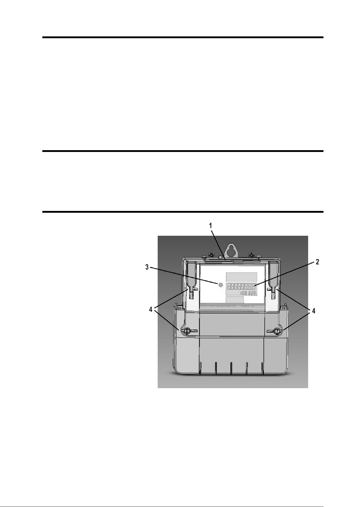
4. PRODUKTBESCHREIBUNG
1 Datenschnittstelle (D0)
2 LC-Display
3 Prüf-LED
4 Benutzersicherungen
Die Zählergehäuse sind verschweißt und als “Sealed-forever” Geräte ausgeführt.
Die Impulsausgänge haben eine Konstante von 10.000 imp/kWh und sind nur aktiv, wenn Energie gezählt wird. Die Geräte haben eine rück-
wirkungsfreie, nur sendende optische D0-Schnittstelle nach DIN EN 62056.
4
Page 5

5
5. SICHERHEITSHINWEISE
Bei Schäden, die durch Nichtbeachten dieser Bedienungsanleitung verursacht werden, erlischt die Gewährleistung/
Garantie! Für Folgeschäden übernehmen wir keine Haftung!
Bei Sach- oder Personenschäden, die durch unsachgemäße Handhabung oder Nichtbeachten der Sicherheitshinweise
verursacht werden, übernehmen wir keine Haftung! In solchen Fällen erlischt die Gewährleistung/Garantie!
Achtung!
Die Installation des Produkts darf nur durch eine qualifizierte Elektrofachkraft (z.B. Elektriker) erfolgen, die mit den ein-
schlägigen Vorschriften (z.B. VDE) vertraut ist!
Durch unsachgemäße Arbeiten an der Netzspannung gefährden Sie nicht nur sich selbst, sondern auch andere!
Haben Sie keine Fachkenntnisse für die Montage, so nehmen Sie die Montage nicht selbst vor, sondern beauftragen Sie
einen Fachmann (z.B. Klappt Meisterservice).
• Alle Bestandteile des Systems haben das Werk in sicherheitstechnisch einwandfreiem Zustand verlassen. Um diesen Zustand
zu erhalten und einen gefahrlosen Betrieb sicherzustellen, muss der Anwender die Sicherheitshinweise und Warnvermerke
beachten, die in dieser Gebrauchsanweisung enthalten sind.
• Diese Teilprodukte sind mit hoch integrierten Bausteinen bestückt. Diese elektronischen Bauteile sind sehr empfindlich gegen
Entladung statischer Elektrizität. Bitte berühren Sie deshalb keine metallischen Kontakte und besonders keine Steckbuchsen.
• Aus Sicherheits- und Zulassungsgründen (CE) ist das eigenmächtige Umbauen und/oder Verändern der Schaltung des
Produkts nicht gestattet.
• Beim Umgang mit Produkten, die mit elektrischer Spannung in Berührung kommen können, müssen die gültigen VDE
Vorschriften beachtet werden, insbesondere VDE 0100, VDE 0550/0551, VDE 0700, VDE 0711 und VDE 0860.
• Wenden Sie sich an eine Fachkraft, wenn Sie Zweifel über die Arbeitsweise, die Sicherheit oder den Anschluss des Produkts
haben.
•
Das Produkt darf nur in Betrieb genommen werden, wenn es vorher berührungssicher eingebaut wurde. Während des Einbaus
muss der Installationsbereich stromlos sein. Alle Verdrahtungsarbeiten dürfen nur im spannungslosen Zustand ausgeführt werden.
• Der direkte Kontakt der Platine und Steckkontakte mit Wasser ist unbedingt zu vermeiden.
• Arbeiten Sie mit dem Produkt nicht in Räumen oder bei widrigen Umgebungsbedingungen, in/bei denen brennbare Gase,
Dämpfe oder Stäube vorhanden sind oder vorhanden sein können.
• Überprüfen Sie vor jeder Inbetriebnahme das Produkt und dessen Leitungen auf Beschädigung(en). Wenn anzunehmen ist,
dass ein gefahrloser Betrieb nicht mehr möglich ist, so ist das Produkt außer Betrieb zu setzen und gegen unbeabsichtigten
Betrieb zu sichern. Es ist anzunehmen, dass ein gefahrloser Betrieb nicht mehr möglich ist, wenn:
- das Gerät sichtbare Beschädigungen aufweist
- das Gerät nicht mehr arbeitet
- nach längerer Lagerung unter ungünstigen Verhältnissen
- nach schweren Transportbeanspruchungen
• Schalten Sie das Produkt niemals gleich dann ein, wenn dieses von einem kalten in einen warmen Raum gebracht wurde. Das
dabei entstandene Kondenswasser kann unter Umständen Ihr Produkt zerstören. Lassen Sie das Produkt ausgeschaltet auf
Zimmertemperatur erwärmen.
• Lassen Sie das Verpackungsmaterial nicht achtlos liegen; dieses könnte für Kinder zu einem gefährlichen Spielzeug werden.
• In Schulen und Ausbildungseinrichtungen, Hobby- und Selbsthilfewerkstätten ist der Umgang mit technischen Geräten durch
geschultes Personal verantwortlich zu überwachen.
• In gewerblichen Einrichtungen sind die Unfallverhütungsvorschriften des Verbandes der gewerblichen Berufsgenossenschaften
für elektrische Anlagen und Betriebsmittel zu beachten.
• Eine andere Verwendung als beschrieben führt zur Beschädigung dieses Produktes; außerdem ist dies mit Gefahren, wie z.B.
Kurzschluss, Brand, elektrischer Schlag etc. verbunden.
Ꮨ
Page 6
6. BETRIEBSBEDINGUNGEN
Der Drehstromzähler „VSM-105“ darf als 4-Leiter Zähler (3 x 230/400 V) oder als 2-Leiter Zähler (230 V in L2) in Zählerplatzsystemen mit
Zählerräumen nach DIN VDE0603 Teil 1, DIN 43853 eingesetzt werden. Der maximale Grenzstrom von 60A sollte nicht überschritten werden.
Der Zähler erfüllt unter diesen Bedingungen die Genauigkeitsklasse Anach EN50470.
Der Zähler erfüllt die Schutzklasse II sowie das Gehäuse die Schutzart IP54; er kann bei Temperaturen von -25 °C bis +55 °C und einer
Luftfeuchtigkeit von <100% eingesetzt werden.
7. BEDIENUNG DES 3-PHASEN-/4-LEITER-ZÄHLERS
a) Allgemeine Displayfunktionen
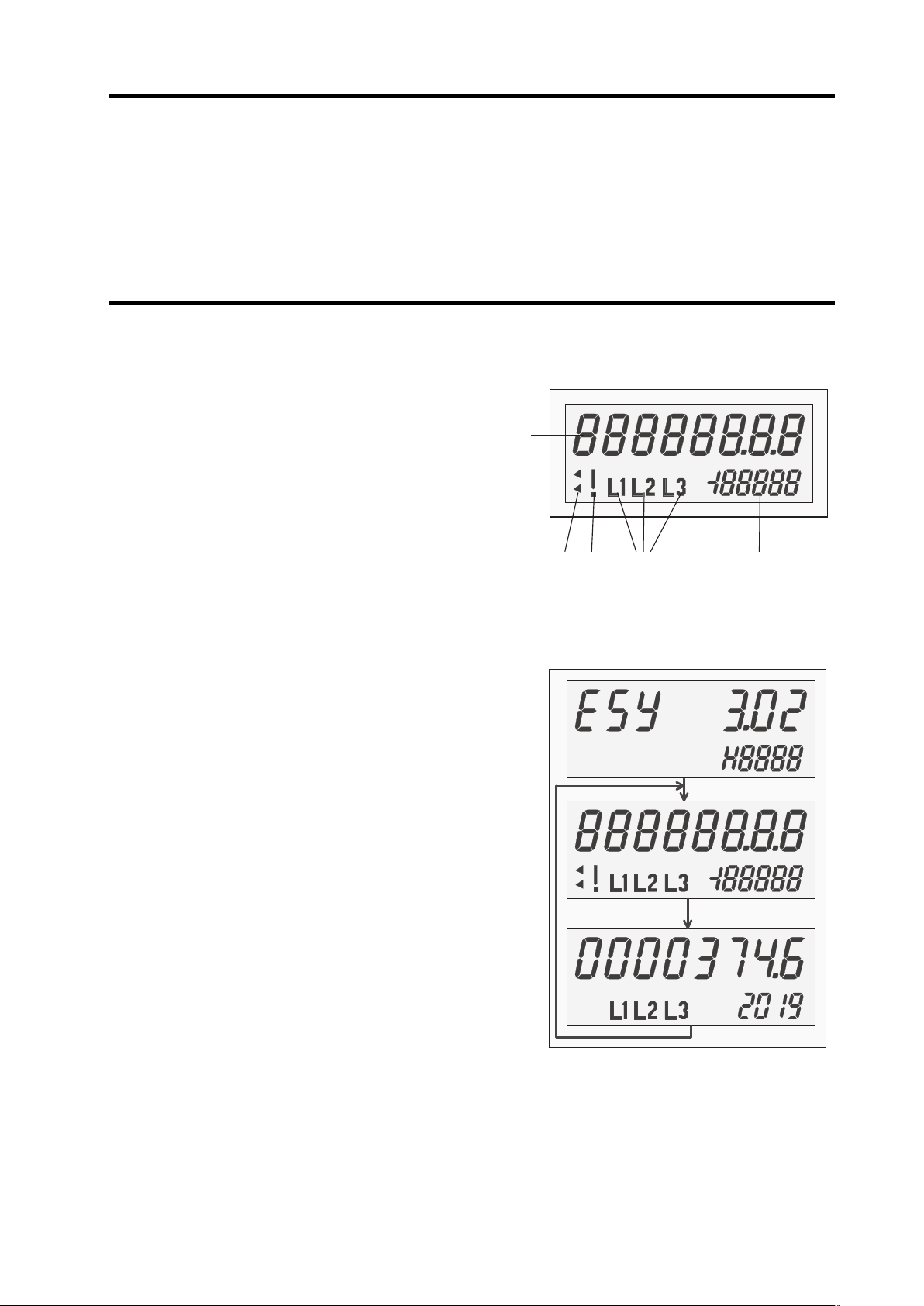
Als Anzeige dient eine nicht hinterleuchtete Flüssigkristallanzeige (LCD) mit folgenden Zeichen / Symbolen.
1 Energieanzeige in kWh (Zählwerksstand) 8 Stellen (1 Nachkommastelle)
2 Zusatzfelder, z.B. für die Anzeige von Bezug und Lieferung, nur bei
Zweirichtungszählern
3 Ausrufezeichen blinkt, wenn die Energie nicht gezählt wird, z.B. wenn bei
einem reinen Bezugszähler mit Rücklaufsperre Energie ins Netz einge-
speist wird.
4 Anliegende Leiterspannungen
5 Ziffernblock mit 5
1
/2Stellen und Vorzeichen für Leistungsanzeige in Watt
bzw. Funktionsfehleranzeige
b) Anzeige der Betriebszustände, Ablauf beim Zweirichtungszähler
Firmwareversion des Programmcodes, Anzeigedauer ca. 2 Sekunden
Displaytest (Anzeige aller Segmente), Anzeigedauer ca. 2 Sekunden
Betriebsanzeige mit Anzeige des Energiewertes, der Momentanleistung und
der angeschlossenen Leiter
Aktualisierung der Anzeige jede Sekunde, Anzeigedauer ca. 60 Sekunden
6
1
5432
Page 7
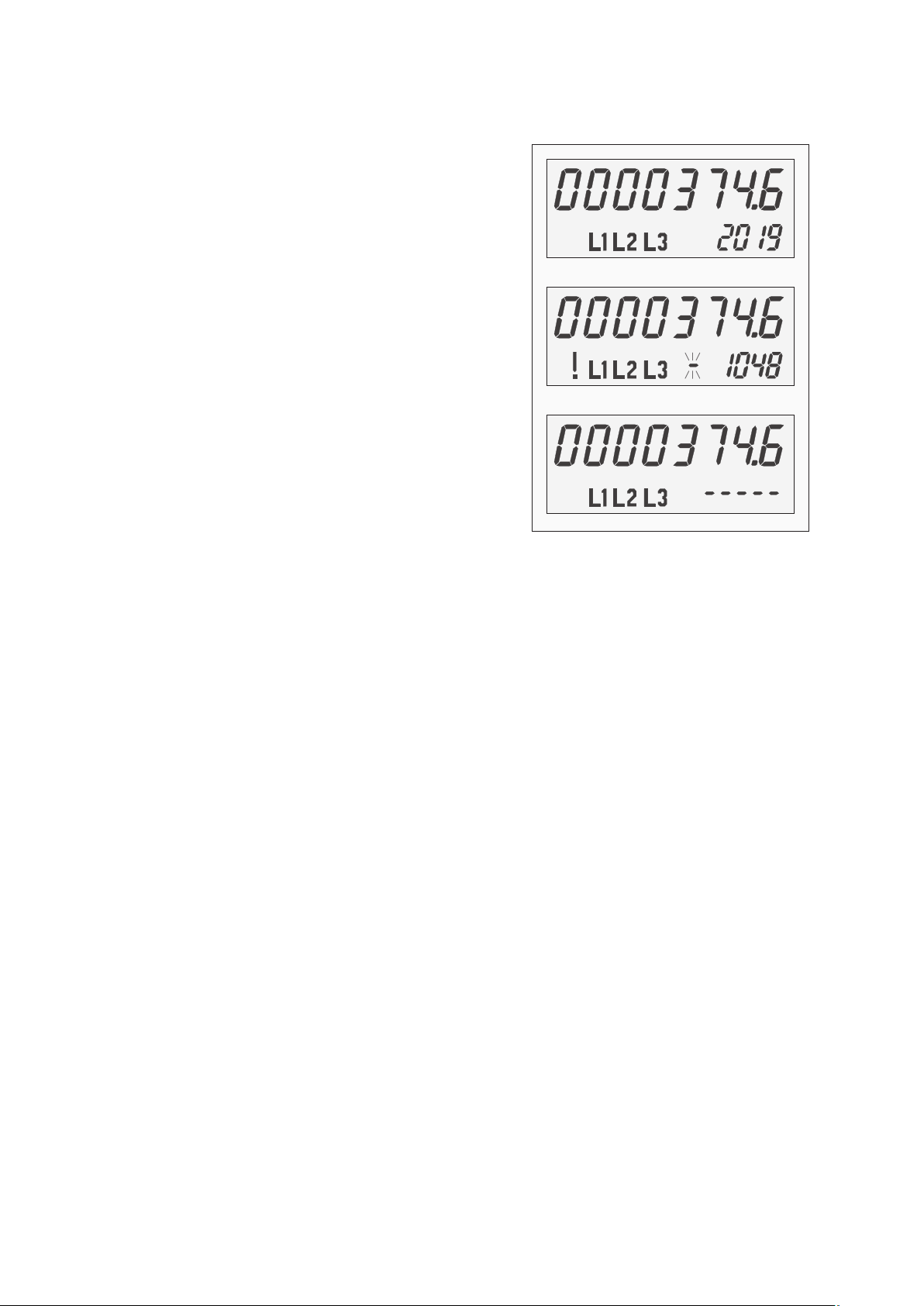
c) Anzeige der aktuellen Leistung
Die Leistung wird im Sekundentakt aktualisiert dargestellt. Es erfolgt eine Mittelwertbildung aus dem aktuellen Messwert und den letzten drei
Werten.
Jeweils obere Zeile: Energiewert (mit einer Nachkommastelle) in kWh
Untere Zeile rechts: Summe der Momentleistungen der Phasen L1, L2, L3,
mindestens eine liegt oberhalb der Anlaufschwelle
Summe der Momentleistungen der Phasen L1, L2, L3 ist negativ: Leistung
wird mit blinkendem Minus-Zeichen angezeigt
Ausrufezeichen erscheint: Energie wird nicht gezählt (Rücklaufsperre)
Jede der Phasen-Momentleistungen in L1, L2, L3 liegt unterhalb der
Anlaufschwelle: Leistung „0“ wird angezeigt (5 Mittelstriche), Energie wird
nicht gezählt (Leerlaufsperre)
7
Page 8

8. FUNKTIONSFEHLER
Zur Überwachung von Funktionsfehlern ist der „VSM-105“ mit einer Fehlererkennung ausgestattet. Wird einer der folgenden Fehler erkannt,
wird das interne Energieregister auf dem aktuellen Stand „eingefroren“. Das Ausrufezeichen blinkt, die Fehlercodes werden im Display angezeigt und sind nicht löschbar (Beispiel: „FF002“). Der Zähler muss ausgebaut werden.
Beim Zweirichtungszähler werden die Energiewerte beider Register abwechselnd angezeigt.
Anzeige Fehlerbeschreibung
FF001 Hardwarefehler
FF002 Parameterfehler
FF003 Energie-Speicher (EEPROM) fehlerhaft
9. OPTISCHER IMPULSAUSGANG
Der VSM-105 besitzt einen optischen Prüfausgang nach EN50470-1 (Pulsausgang). Die Pulskonstante beträgt 10.000 Impulse/kWh bei einer
Impulslänge von 2 ms. Die rote LED gibt keine weiteren Signalzustände aus und ist unterhalb der Anlaufschwelle inaktiv.
10. DATENSCHNITTSTELLE
Die Datenschnittstelle des Zählers ist eine optische (Infrarot-) Kommunikationsschnittstelle (D0).
Es werden folgende Messwerte ausgegeben:
• der Zählwerksstand Etot (15-stellig in kWh, mit 8 Vor- und 7 Nachkommastellen)
• die Phasenleistungen PL1, PL2, PL3 (7
1
/2-stellig in W, 2 Nachkommastellen, Vorzeichen)
• die Summenleistung Ptot (7
1
/2-stellig in W, 2 Nachkommastellen, Vorzeichen)
Das Protokoll ist nach EN62056-21 und EN62056-61 ausgeführt.
Der Zähler sendet alle zwei Sekunden unidirektional einen Datensatz.
8
Page 9

11. AUFBAU DES DATENTELEGRAMMS
a) Allgemein
Telegram Mode D nach DIN EN 625056-21
Baudrate 9600 Baud (Z=5)
Byte Format 7E1 (1 Startbit, 7 Datenbits, even Parity, 1 Stoppbit)
b) Struktur der Datentelegramme
Ziel / Bedeutung OBIS Kommentar
Hersteller-Identifikation Siehe DIN EN62056-21
(20 Zeichen max., z.B. Q3DB3004 V3.02)
Eigentumsnummer 1-0:0.0.0*255 Max. 20 Zeichen
Zählerstand 1-0:1.8.0*255 Wird stets mit einer Auflösung von 0,1mWh gespeichert
(Wirkenergie +A) (z.B. 12345678.1234567*kWh – kein Unterschied
zwischen 8+0 , 7+1 und 6+2 Anzeige im Display)
L1 + Active Power 1-0:21.7.255*255 Momentane Leistung – 6 Stellen + 2 Nachkommastellen in W
(momentane Leistung P1) mit Vorzeichen (-123456,12*W)
L2 + Active Power 1-0:41.7.255*255 Momentane Leistung – 6 Stellen + 2 Nachkommastellen in W
(momentane Leistung P2) mit Vorzeichen (-123456,12*W)
L3 + Active Power 1-0:61.7.255*255 Momentane Leistung – 6 Stellen + 2 Nachkommastellen in W
(momentane Leistung P3) mit Vorzeichen (-123456,12*W)
⌺ Li+ Active Power 1-0:1.7.255*255 Momentane Summe der Leistung – 6 Stellen + 2 Nachkomma-
(momentane Summe der Leistung) stellen in W mit Vorzeichen (-123456,12*W)
Statusinformation 1-0:96.5.5*255 Das Statuswort wird als ein Byte definiert und in
hexadezimaler Darstellung übertragen.
Es gilt folgende Zuordnung:
Bit[7] – MSB, 0=Leerlauf, 1=oberhalb Anlauf
Bit[6] – wird bei Ausfall von L1 gesetzt
Bit[5] – wird bei Ausfall von L2 gesetzt
Bit[4] – wird bei Ausfall von L3 gesetzt
Bit[3:2] – reserviert, immer 0
Bit[1] –
‚1’ das Telegramm wird immer synchron
im festen
Zeitraster ausgegeben
Bit[0] – ‚0’ kein Fehler, ‚1’ – Fehler
Fabriknummer 0-0:96.5.5*255 Herstellernummer (max. 20 Zeichen)
9
Page 10

12. ENTSORGUNG
Entsorgen Sie das Produkt am Ende seiner Lebensdauer gemäß den geltenden gesetzlichen Vorschriften; geben Sie es z.B. bei einer
entsprechenden Sammelstelle ab.
13. TECHNISCHE DATEN DES ZÄHLERS
Zählertyp: ....................................................Drehstromzähler (mit Rücklaufsperre)
Zählart: ........................................................Nur positive Energiezählung, Rücklaufsperre (wie Motorzähler)
Genauigkeitsklasse: ..................................Klasse A (2%) gemäß EN50470-1
Referenzstrom I
ref
: ......................................5 A
Grenzstrom I
max
: ........................................60 A
Anlaufstrom I
st
: ..........................................10 mA
Mindeststrom I
min
: ......................................100 mA
Übergangsstrom I
tr
: ....................................500 mA
Referenzspannung U
n
: ..............................4-Leiter Zähler: 3 x 230/400 V, 2-Leiter Zähler: 230 V in L2
Referenzfrequenz f
n
: ..................................50 Hz
Zählerkonstante: ........................................LED – Ausgang (rot) mit 10.000 Imp/kWh
LC-Anzeige: ................................................7 Vorkomma-, 1 Nachkommastelle
Klemmen-Ø: ..............................................8 Klemmen, jede mit Ø 6.5 mm (60 A DIN), Schrauben 2 x M5 pro Klemme
Ausgänge: ..................................................Optischer Pulsausgang entsprechend EN50470-1
Gewicht: ....................................................ca. 0,6 kg
Schutzklasse: ............................................II
Schutzart (Gehäuse): ................................IP54
Leistungsaufnahme: ..................................<=0,005 W bei 5 A/ <=1,1 W bei 60 A im Strompfad
<=0,6 W / 2,5 VAim Spannungspfad
Temperaturbereich: ....................................-25 °C bis +55 °C
Luftfeuchtigkeit: ..........................................<100 %
Mechanische / EMV Anforderungsklasse: ..M1 / E2
Einsatz des Zählers: ..................................Innenraum
Abmessungen: ............................................191 x 177 x 50 mm
Montage
Empfohlener Leiterquerschnitt zum Anschluss des Zählers: ........16 mm
2
Max. Anzugsdrehmoment der Klemmenschrauben: ....................<=3 Nm
Klemmendeckel in 4 Längen erhältlich: ........................................30, 60, 80, 100 mm
Eine schiefe Montage des Zählers hat keinen Einfluss auf die Messtechnik.
10
Page 11
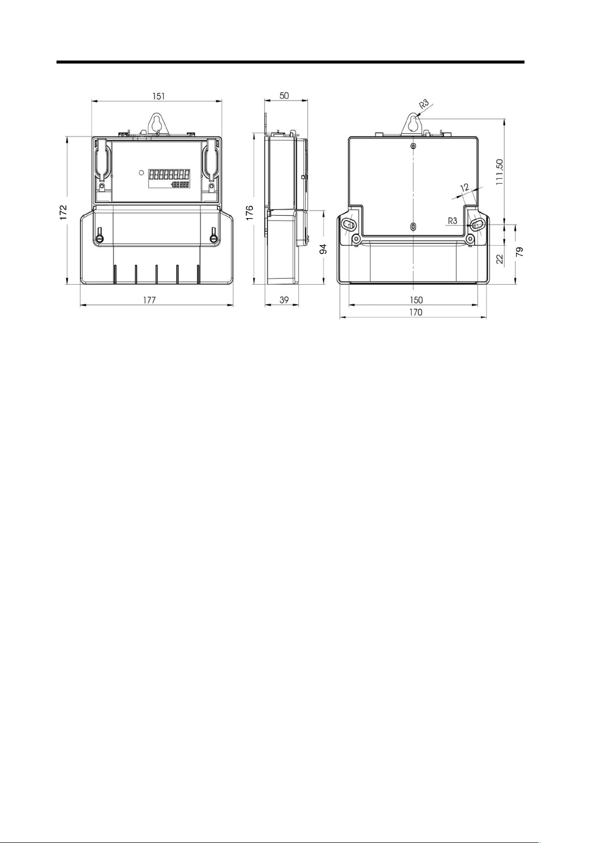
14. MASSBLATT Q3DA1004
11
Page 12

TABLE OF CONTENTS
PAG E
1. INTRODUCTION . . . . . . . . . . . . . . . . . . . . . . . . . . . . . . . . . . . . . . . . . . . . . . . . . . . . . . . . . . . . . . . . . . . . . . . . . . . . . . . . . . .12
2. INTENDED USE . . . . . . . . . . . . . . . . . . . . . . . . . . . . . . . . . . . . . . . . . . . . . . . . . . . . . . . . . . . . . . . . . . . . . . . . . . . . . . . . . . . .13
3. SCOPE OF DELIVERY . . . . . . . . . . . . . . . . . . . . . . . . . . . . . . . . . . . . . . . . . . . . . . . . . . . . . . . . . . . . . . . . . . . . . . . . . . . . . .13
4. PRODUCT DESCRIPTION . . . . . . . . . . . . . . . . . . . . . . . . . . . . . . . . . . . . . . . . . . . . . . . . . . . . . . . . . . . . . . . . . . . . . . . . . . .13
5. SAFETY NOTES . . . . . . . . . . . . . . . . . . . . . . . . . . . . . . . . . . . . . . . . . . . . . . . . . . . . . . . . . . . . . . . . . . . . . . . . . . . . . . . . . . .14
6. OPERATING CONDITIONS . . . . . . . . . . . . . . . . . . . . . . . . . . . . . . . . . . . . . . . . . . . . . . . . . . . . . . . . . . . . . . . . . . . . . . . . . . .15
7. OPERATION OF THE 3-PHASE-/4-CONDUCTOR METER . . . . . . . . . . . . . . . . . . . . . . . . . . . . . . . . . . . . . . . . . . . . . . . . . .15
a) General Display Functions . . . . . . . . . . . . . . . . . . . . . . . . . . . . . . . . . . . . . . . . . . . . . . . . . . . . . . . . . . . . . . . . . . . . . . . . .15
b) Operating State Display, Standard Supply Meter Process . . . . . . . . . . . . . . . . . . . . . . . . . . . . . . . . . . . . . . . . . . . . . . . . .15
c) Display of the Current Output . . . . . . . . . . . . . . . . . . . . . . . . . . . . . . . . . . . . . . . . . . . . . . . . . . . . . . . . . . . . . . . . . . . . . . .16
8. FUNCTIONAL ERROR . . . . . . . . . . . . . . . . . . . . . . . . . . . . . . . . . . . . . . . . . . . . . . . . . . . . . . . . . . . . . . . . . . . . . . . . . . . . . .17
9. OPTICAL IMPULSE OUTPUT . . . . . . . . . . . . . . . . . . . . . . . . . . . . . . . . . . . . . . . . . . . . . . . . . . . . . . . . . . . . . . . . . . . . . . . . .17
10. DATA INTERFACE . . . . . . . . . . . . . . . . . . . . . . . . . . . . . . . . . . . . . . . . . . . . . . . . . . . . . . . . . . . . . . . . . . . . . . . . . . . . . . . . . .17
11. DATA TELEGRAM STRUCTURE . . . . . . . . . . . . . . . . . . . . . . . . . . . . . . . . . . . . . . . . . . . . . . . . . . . . . . . . . . . . . . . . . . . . . .18
a) General Information . . . . . . . . . . . . . . . . . . . . . . . . . . . . . . . . . . . . . . . . . . . . . . . . . . . . . . . . . . . . . . . . . . . . . . . . . . . . . . .18
b) Data Telegram Structure . . . . . . . . . . . . . . . . . . . . . . . . . . . . . . . . . . . . . . . . . . . . . . . . . . . . . . . . . . . . . . . . . . . . . . . . . . .18
12. DISPOSAL . . . . . . . . . . . . . . . . . . . . . . . . . . . . . . . . . . . . . . . . . . . . . . . . . . . . . . . . . . . . . . . . . . . . . . . . . . . . . . . . . . . . . . . .19
13. TECHNICAL METER DATA . . . . . . . . . . . . . . . . . . . . . . . . . . . . . . . . . . . . . . . . . . . . . . . . . . . . . . . . . . . . . . . . . . . . . . . . . .19
14. DIMENSION SHEET Q3DA1004 . . . . . . . . . . . . . . . . . . . . . . . . . . . . . . . . . . . . . . . . . . . . . . . . . . . . . . . . . . . . . . . . . . . . . . .20
1. INTRODUCTION
Dear Customer,
In purchasing this Voltcraft® product, you have made a very good decision for which we would like to thank you.
Voltcraft® - In the field of measuring, charging and network technology, this name stands for high-quality products which perform superbly and
which are created by experts whose concern is continuous innovation.
From the ambitious hobby electronics enthusiast to the professional user, products from the Voltcraft® brand family provide the optimum solu-
tion even for the most demanding tasks. Moreover, we offer you the mature technology and reliable quality of our Voltcraft® products at an
almost unbeatable price-performance ratio. In this way, we aim to establish a long, fruitful and successful co-operation with our customers.
We wish you a great deal of enjoyment with your new Voltcraft® product!
All company names and product names are trademarks of their respective owners. All rights reserved.
12
Page 13

2. INTENDED USE
The product is used as 3-phase/4-conductor or single-phase alternate current meter (L2) in meter place systems with meter rooms pursuant
to DIN VDE0603 part 1, DIN 43853.
With the “VSM-105-receiver” (Conrad order no. 125447), the meter is compatible with “Gateway VSM-101” and can be evaluated with the
“VSA” evaluation software.
Any use other than that described above is not permitted. Misuse may not only damage the device, but also leads to risks such as short circuiting, fire, electrical shocks. The product may not be altered or converted. The safety notes and the maximum permissible operational and
ambient conditions stated in the chapter “Technical Information” must be observed at all times.
Read these operating instructions thoroughly and carefully, they contain a lot of important information for assembly, commissioning and operation.
3. SCOPE OF DELIVERY
• VSM-105-60 meter
• Operating instructions
4. PRODUCT DESCRIPTION
1 Data interface (D0)
2 LC display
3 Test LED
4 User fuses
The meter casings are welded and performed as “sealed forever” devices.
The impulse outputs have a constant rate of 10,000 imp/kWh and are only active when energy is measured. The devices have a repercus-
sion-free, transmission-only optical D0 interface pursuant to DIN EN 62056.
13
Page 14

5. SAFETY NOTES
The guarantee/warranty will be void if damage is incurred resulting from non-compliance with the operating instructions!
We do not assume any responsibility for consequential damage!
We do not assume any liability for property damage and personal injury caused by improper use or non-compliance with
the safety instructions! In such cases the guarantee/warranty will be void.
Attention!
The product may only be installed by a qualified electrical specialist (e.g. electrician) who is familiar with the relevant
regulations (e.g. VDE, German electrical wiring regulations).
Improper work carried out at the mains supply endangers not only your life but also the lives of others!
If you do not have expertise in the assembly do not perform it yourself but instruct a qualified expert (e.g. Klappt master
service).
• All system components left the factory in perfect condition in terms of safety engineering. We kindly request that you as a user
observe the safety instructions and warnings contained in this operating manual to preserve this condition and to ensure safe
operation!
• These partial products are equipped with highly integrated components. Electronic components are very sensitive to static elec-
tricity discharge. Therefore, please do not touch any metal contacts and in particular no plug sockets.
• Unauthorised conversion and/or modification of the product switching is inadmissible for safety and approval reasons (CE).
• When handling devices that may come into contact with electric voltage, you have to observe the valid VDE regulations, espe-
cially VDE 0100, VDE 0550/0551, VDE 0700, VDE 0711 and VDE 0860.
• Consult an expert if you are unsure of how to use or connect the device, or if the safety instructions are not clear to you.
•
The module may only be operated after it has been installed touch-proof. The power must be switched off in the installation area
when installing. All wiring work must be performed with the power switched off.
• Direct contact of the circuit board and plug contacts with water must be avoided at all times!
• Do not operate the product in rooms or under unfavourable conditions where combustible gases, vapours or dust are or may be
present.
• Prior to each setup, check your product and its cables for damage. If it can be assumed that safe operation is no longer possi-
ble, the device must be turned off and precautions are to be taken to ensure that it is not used unintentionally. It must be
assumed that safe operation is no longer possible if:
- the device shows visible signs of damage
- the device no longer operates
- the device has been stored under unfavourable conditions for a longer period of time
- following heavy stress during transportation.
• Do not switch the product on immediately after it has been taken from a cold to a warm environment. The condensation that
forms might destroy your product. Allow the product to reach room temperature before switching it on.
• Do not leave the packaging material lying around carelessly since such materials can become dangerous toys in the hands of
children.
• In schools, training centres, computer and self-help workshops, handling of technical devices must be supervised by trained per-
sonnel in a responsible manner.
• In commercial institutions, the accident prevention regulations of the Employer’s Liability Insurance Association for Electrical
Systems and Operating Materials are to be observed.
• Use other than that described can lead to damage to the product and may involve additional risks such as, for example, short
circuits, fire, electrical shocks etc.
14
Ꮨ
Page 15

6. OPERATING CONDITIONS
The rotary current meter “VSM-105” can be used as a 4-conductor meter (3 x 230/400 V) or as a 2-conductor meter (230 V in L2) in meter
place systems with meter rooms pursuant to DIN VDE0603 part 1, DIN 43853. The maximum threshold current of 60A should not be exceeded. Under these conditions, the meter complies with accuracy class Apursuant to EN50470.
The meter complies with protection class II and the casing with protection class IP54; it can be used in temperatures of -25 °C to +55 °C and
a humidity of <100%.
7. OPERATION OF THE 3-PHASE-/4-CONDUCTOR METER
a) General Display Functions
The display is a non-backlit liquid crystal display (LCD) with the following signs / symbols.
1 Power display in kWh (meter state) 8 digits (1 decimal digit)
2 Additional fields, e.g. for supply and delivery display, only for two-direction-
al meters
3 Exclamation mark flashes when no power is counted, e.g. if power is fed
into the mains in a pure supply with backflow lock.
4 Applied conductor voltages
5 Keypad with 5
1
/2digits and prefix for power display in watt or functional
error display
b) Operating State Display, Two-Directional Meter Process
Programme code firmware version, display duration approx. 2 seconds
Display test (display of all segments) display duration approx. 2 seconds
Operation display with power value display, current output and connected
conductors
Display update every second, display duration approx. 60 seconds
15
1
5432
Page 16

c) Display of the Current Output
The output display is updated every second. The average value is formed from the current measured value and the last three values.
Upper line each: Power value (with one decimal digit) in kWh
Lower line, right: Sum of current outputs of phases L1, L2, L3, at least one is
above the start-up threshold
Sum of current outputs of phases L1, L2, L3 is negative: Output is displayed
with a flashing minus sign
Exclamation mark appears: Power is not counted (backflow lock)
Each of current phase outputs L1, L2, L3 is below the start-up threshold
Output “0” is displayed (5 centre dashes), power is not counted (idle lock)
16
Page 17

8. FUNCTION ERROR
The “VSM-105” is equipped with error recognition to monitor for functional errors. If one of the following errors is recognised, the internal
power register is “frozen” on the current state. The exclamation mark flashes, the error codes are indicated in the display and cannot be deleted
(example: “FF002”). The meter must be uninstalled.
For the two-directional meter, the power values for the two registers are displayed alternatingly.
Display Error description
FF001 Hardware error
FF002 Parameter error
FF003 Energy storage (EEPROM) defective
9. OPTICAL IMPULSE OUTPUT
The VSM-105 has an optical test output pursuant to EN50470-1 (impulse output). The pulse constant is 10,000 impulses/kWh at an impulse
length of 2 ms. The red LED does not output any further signal states and is inactive below the start-up threshold.
10. DATA INTERFACE
The meter’s data interface is an optical (infrared) communication interface (D0).
The following measured values are output:
• The meter state Etot (15-digit in kWh, with 8 pre- and 7 post-decimal digits)
• The phase outputs PL1, PL2, PL3 (7
1
/2-digit in W, 2 decimal digits, prefix)
• The sum output Ptot (7
1
/2-digit in W, 2 decimal digits, prefix)
The protocol is designed pursuant to EN62056-21 and EN62056-61.
The meter unidirectionally sends a dataset every two seconds.
17
Page 18

11. DATA TELEGRAM STRUCTURE
a) General information
Telegram mode D pursuant to DIN EN 625056-21,
Baud rate 9600 Baud (Z=5)
Byte format 7E1 (1 starting bit, 7 data bits, even parity, 1 stop bit)
b) Data Telegram Structure
Target / meaning OBIS Comment
Manufacturer identification See DIN EN62056-21
(20 characters max., e.g. Q3DB3004 V3.02)
Property number 1-0:0.0.0*255 max. 20 characters
Meter state 1-0:1.8.0*255 Is always stored in a resolution of 0.1 mWh
(effective energy +A) (e.g. 12345678.1234567*kWh – no difference
between 8+0 , 7+1 and 6+2 indicated on the display)
L1 + Active Power 1-0:21.7.255*255 Current output – 6 digits + 2 decimal digits in W
(current output P1) with prefix (-123456.12*W)
L2 + Active Power 1-0:41.7.255*255 Current output – 6 digits + 2 decimal digits in W
(current output P2) with prefix (-123456.12*W)
L3 + Active Power 1-0:61.7.255*255 Current output – 6 digits + 2 decimal digits in W
(current output P3) with prefix (-123456.12*W)
S Li+ Active Power 1-0:1.7.255*255 Current output sum – 6 digits + 2 decimal
(current output sum) digits in W with prefix (-123456.12*W)
Status information 1-0:96.5.5*255 The status word is defined as one byte and
transmitted in hexadecimal indication
The following assignment applies:
Bit[7] – MSB, 0=idle, 1=above start-up
Bit[6] – is set in case of outage of L1
Bit[5] – is set in case of outage of L2
Bit[4] – is set in case of outage of L3
Bit[3:2] – reserved, always 0
Bit[1] –
‘1’ the telegram is always output synchronously
in the
fixed time grid
Bit[0] – ‘0’ no error, ‘1’ – error
Factory number 0-0:96.5.5*255 Manufacturer number (max. 20 characters)
18
Page 19

12. DISPOSAL
Dispose of the product at the end of its serviceable life in accordance with the current statutory requirements; e. g. return it to any suitable collecting point.
13. TECHNICAL METER DATA
Meter type: ..................................................Rotary current meter (with backflow lock)
Meter type: ..................................................Only positive energy counted, backflow lock (like motor counter)
Accuracy class ..........................................Class A (2%) pursuant to EN50470-1
Reference current I
ref
: ................................5 A
Threshold current I
max
: ..............................60 A
Start-up current I
st
: ....................................10 mA
Minimum current I
min
: ................................100 mA
Transition current I
tr
: ..................................500 mA
Reference voltage U
n
: ................................4-conductor meter: 3 x 230/400 V, 2-conductor meter: 230 V in L2
Reference frequency f
n
: ............................50 Hz
Meter constant: ..........................................LED output (red) at 10,000 Imp/kWh
LC display: ..................................................7 pre-decimal-, 1 post-decimal digit
Clamp Ø: ....................................................8 clamps, each at Ø 6.5 mm (60 ADIN), screws 2 x M5 per clamp
Outputs: ......................................................Optical impulse output according to EN50470-1
Weight: ......................................................Approx. 0.6 kg
Protection class: ........................................II
Protection type (casing): ............................IP54
Power consumption: ..................................<=0.005 W at 5 A / <=1.1 W at 60 A in the power path
<=0.6 W / 2.5 VAin the voltage path
Temperature range: ....................................-25 °C to +55 °C
Air humidity: ................................................<100 %
Mechanical /( EMC requirement class: ......M1 / E2
Meter use: ..................................................Indoors
Dimensions: ................................................191 x 177 x 50 mm
Assembly
Recommended conductor cross-section for connecting the meter: ....16 mm
2
Max. tightening torque of the clamp screws: ......................................<=3 Nm
Clamp lid available in 4 lengths. ..........................................................30, 60, 80, 100 mm
Slanted installation of the meter does not influence the measuring unit.
19
Page 20

14. DIMENSION SHEET Q3DA1004
20
Page 21

TABLE DES MATIÈRES
PAGE
1. INTRODUCTION . . . . . . . . . . . . . . . . . . . . . . . . . . . . . . . . . . . . . . . . . . . . . . . . . . . . . . . . . . . . . . . . . . . . . . . . . . . . . . . . . . .21
2. UTILISATION CONFORME . . . . . . . . . . . . . . . . . . . . . . . . . . . . . . . . . . . . . . . . . . . . . . . . . . . . . . . . . . . . . . . . . . . . . . . . . . .22
3. CONTENU DE LA LIVRAISON . . . . . . . . . . . . . . . . . . . . . . . . . . . . . . . . . . . . . . . . . . . . . . . . . . . . . . . . . . . . . . . . . . . . . . . .22
4. DESCRIPTION DU PRODUIT . . . . . . . . . . . . . . . . . . . . . . . . . . . . . . . . . . . . . . . . . . . . . . . . . . . . . . . . . . . . . . . . . . . . . . . . .22
5. CONSIGNES DE SÉCURITÉ . . . . . . . . . . . . . . . . . . . . . . . . . . . . . . . . . . . . . . . . . . . . . . . . . . . . . . . . . . . . . . . . . . . . . . . . .23
6. CONDITIONS DE SERVICE . . . . . . . . . . . . . . . . . . . . . . . . . . . . . . . . . . . . . . . . . . . . . . . . . . . . . . . . . . . . . . . . . . . . . . . . . .24
7. COMMANDE DU COMPTEUR TRIPHASÉ À 4 FILS . . . . . . . . . . . . . . . . . . . . . . . . . . . . . . . . . . . . . . . . . . . . . . . . . . . . . . .24
a) Fonctions générales de l’écran . . . . . . . . . . . . . . . . . . . . . . . . . . . . . . . . . . . . . . . . . . . . . . . . . . . . . . . . . . . . . . . . . . . . . .24
b) Affichage des états de fonctionnement, déroulement avec le compteur de consommation standard . . . . . . . . . . . . . . . .24
c) Affichage de la puissance actuelle . . . . . . . . . . . . . . . . . . . . . . . . . . . . . . . . . . . . . . . . . . . . . . . . . . . . . . . . . . . . . . . . . . .25
8. DYSFONCTIONNEMENTS . . . . . . . . . . . . . . . . . . . . . . . . . . . . . . . . . . . . . . . . . . . . . . . . . . . . . . . . . . . . . . . . . . . . . . . . . . .26
9. SORTIE D’IMPULSION OPTIQUE . . . . . . . . . . . . . . . . . . . . . . . . . . . . . . . . . . . . . . . . . . . . . . . . . . . . . . . . . . . . . . . . . . . . .26
10. INTERFACE DE DONNÉES . . . . . . . . . . . . . . . . . . . . . . . . . . . . . . . . . . . . . . . . . . . . . . . . . . . . . . . . . . . . . . . . . . . . . . . . . .26
11. STRUCTURE DU TÉLÉGRAMME DE DONNÉES . . . . . . . . . . . . . . . . . . . . . . . . . . . . . . . . . . . . . . . . . . . . . . . . . . . . . . . . .27
a) Généralités . . . . . . . . . . . . . . . . . . . . . . . . . . . . . . . . . . . . . . . . . . . . . . . . . . . . . . . . . . . . . . . . . . . . . . . . . . . . . . . . . . . . .27
b) Structure des télégrammes de données . . . . . . . . . . . . . . . . . . . . . . . . . . . . . . . . . . . . . . . . . . . . . . . . . . . . . . . . . . . . . . .27
12. ÉLIMINATION . . . . . . . . . . . . . . . . . . . . . . . . . . . . . . . . . . . . . . . . . . . . . . . . . . . . . . . . . . . . . . . . . . . . . . . . . . . . . . . . . . . . .28
13. CARACTÉRISTIQUES TECHNIQUES DU COMPTEUR . . . . . . . . . . . . . . . . . . . . . . . . . . . . . . . . . . . . . . . . . . . . . . . . . . . .28
14. FICHE DE MESURES Q3DA1004 . . . . . . . . . . . . . . . . . . . . . . . . . . . . . . . . . . . . . . . . . . . . . . . . . . . . . . . . . . . . . . . . . . . . . .29
1. INTRODUCTION
Chère cliente, cher client,
Vous avez pris une très bonne décision en achetant un produit Voltcraft® et nous vous en remercions.
Voltcraft® – Dans le domaine de la technique de mesure, de charge, ainsi que de technique de réseau, ce nom représente des produits de
qualité supérieure qui se distinguent par une compétence technique, une extraordinaire performance et une innovation permanente.
De l’électronicien amateur ambitionné à l’utilisateur professionnel, avec un produit de la famille de la marque Voltcraft®, vous disposez tou-
jours de la solution optimale, même pour les tâches les plus exigeantes. Et notre particularité : nous vous offrons la technique au point et la
qualité fiable de nos produits Voltcraft® à un rapport qualité-prix avantageux presque imbattable. Ainsi, nous créons la base d’une coopération
de longue durée, efficace et fructueuse.
Nous vous souhaitons beaucoup de plaisir et de succès avec notre nouveau produit Voltcraft® !
Tous les noms d’entreprises et appellations de produits contenus dans ce mode d’emploi sont des marques déposées des propriétaires cor-
respondants. Tous droits réservés.
21
Page 22

2. UTILISATION CONFORME
Le produit s’utilise comme compteur triphasé à 4 fils ou comme compteur monophasé (L2) dans les systèmes de tableaux pour compteurs
avec un local des compteurs selon DIN VDE0603, partie 1, DIN 43853.
En liaison avec le « capteur VSM-105 » (référence Conrad 125447), le compteur est compatible avec le « Gateway VSM-101 » et peut être
exploité à l’aide du logiciel d’analyse « VSA ».
Toute utilisation autre que celle décrite est interdite. Ceci pourrait endommager l’appareil et entraîner un risque de court-circuit ou d’électrocution. Le produit ne doit ni être transformé ni modifié. Il convient de respecter les consignes de sécurité ainsi que les conditions de service et
les conditions ambiantes maximales autorisées stipulées dans le chapitre « Caractéristiques techniques ».
Lisez intégralement et attentivement le présent mode d’emploi. Il contient des informations importantes relatives au montage, à la mise en
service et au fonctionnement de l’appareil.
3. CONTENU DE LA LIVRAISON
• Compteur VSM-105-60
• Mode d’emploi
4. DESCRIPTION DU PRODUIT
1 Interface de données (D0)
2 Écran LCD
3 DEL de contrôle
4 Fusibles de l’utilisateur
Les boîtiers du compteur sont soudés et sont vendus comme appareils « Sealed-forever ».
Les sorties d’impulsion ont une constante de 10 000 impulsions/kWh et sont uniquement actives durant le comptage d’énergie. Les appareils
sont équipés d’une interface émettrice optique D0 unidirectionnelle selon DIN EN 62056.
22
Page 23

5. CONSIGNES DE SÉCURITÉ
Tout dommage résultant d’un non-respect du présent mode d’emploi entraîne l’annulation de la garantie !
Nous déclinons toute responsabilité pour les dommages consécutifs !
De même, nous n’assumons aucune responsabilité en cas de dommages matériels ou corporels résultant d’une utilisation de l’appareil non conforme aux spécifications ou du non-respect des présentes consignes de sécurité ! De tels cas
entraînent l’annulation de la garantie !
Attention !
L’installation du produit est réservée aux techniciens spécialisés qualifiés (par ex. électriciens) connaissant parfaitement
les consignes spécifiques en vigueur (par ex. VDE).
Toute intervention non conforme sur le secteur constitue un danger, non seulement pour vous mais aussi pour les autres !
N’effectuez pas le montage vous-même si vous ne disposez pas des connaissances spécifiques au montage. Adressez-
vous alors à un spécialiste (par ex. service après-vente KLAPPT).
• Du point de vue de la sécurité, tous les composants du système ont quitté l’usine dans un état technique irréprochable. Afin de
maintenir l’appareil dans un état irréprochable et de garantir un fonctionnement sans risques, l’utilisateur doit tenir compte des
consignes de sécurité et avertissements stipulés dans le présent mode d’emploi.
• Ces produits partiels sont équipés de modules à haute intégration. Ces composants électroniques sont très sensibles aux
décharges électrostatiques. Ne touchez donc jamais les contacts métalliques et surtout pas les douilles enfichables.
• Pour des raisons de sécurité et d’homologation (CE), il est interdit de modifier la construction et/ou de transformer le produit de
manière arbitraire.
• Lors de la manipulation de produits pouvant entrer en contact avec une tension électrique, les directives VDE en vigueur doi-
vent être observées, notamment les directives VDE 0100, VDE 0550/0551, VDE 0700, VDE 0711 et VDE 0860.
• Si vous avez des doutes concernant le principe de fonctionnement, la sécurité ou le branchement de l’appareil, adressez-vous à
un technicien.
•
Le produit doit uniquement être mis en service après avoir été monté dans un boîtier offrant une protection contre les contacts.
Pendant le montage, la zone de l’installation doit être hors tension. Tous les travaux de câblage doivent uniquement être effectués
hors tension.
• Impérativement éviter tout contact direct de la platine ou des contacts enfichables avec de l’eau.
• N’utilisez pas le produit dans des locaux ou des environnements inappropriés, contenant ou susceptibles de contenir des gaz,
des vapeurs ou des poussières inflammables.
• Avant toute mise en service, assurez-vous que le produit et ses câbles ne soient pas endommagés. S’il est probable qu’une
utilisation sans danger n’est plus possible, le produit doit être mis hors service puis sécurisé afin d’éviter toute utilisation accidentelle. Une utilisation sans danger n’est plus garantie lorsque :
- l’appareil est visiblement endommagé,
- l’appareil ne fonctionne plus,
- l’appareil a été stocké pendant une période prolongée dans des conditions défavorables,
- l’appareil a été soumis à de sévères contraintes durant le transport.
•
N’allumez jamais le produit immédiatement après l’avoir transporté d’un local froid dans un local chaud. L’eau de condensation qui
se forme alors risquerait de détruire le produit. Attendez que le produit ait atteint la température ambiante avant de le brancher.
• Ne laissez pas traîner le matériel d’emballage sans surveillance ; il pourrait constituer un jouet dangereux pour les enfants.
• Dans les écoles, les centres de formation, les ateliers de loisirs et de réinsertion, la manipulation d’appareils techniques doit être
surveillée par un responsable, spécialement formé à cet effet.
• Dans les installations professionnelles, les consignes de prévention des dangers de l’union des associations professionnelles
pour les installations et moyens d’exploitation électriques doivent être respectées.
• Toute utilisation autre que celle décrite peut endommager le produit et présente des dangers tels que court-circuit, incendie,
électrocution, etc.
23
Ꮨ
Page 24

6. CONDITIONS DE SERVICE
Le compteur triphasé « VSM-105 » peut être utilisé comme compteur à 4 fils (3 x 230/400 V) ou comme compteur à 2 fils ((230 V dans L2)
dans les systèmes de tableaux pour compteurs avec un local des compteurs selon DIN VDE0603, partie 1, DIN 43853. Il est conseillé de ne
pas dépasser un courant limite maximal de 60 A. Dans ces conditions, le compteur satisfait aux exigences de la classe de précision A selon
EN50470.
Le compteur satisfait aux exigences de la classe de protection II et le boîtier dispose d’une protection IP54 ; ils peuvent être employés dans
la plage de température comprise entre -25 et +55 °C et avec une humidité de l’air < 100 %.
7. COMMANDE DU COMPTEUR TRIPHASÉ À 4 FILS
a) Fonctions générales de l’écran
Un écran à cristaux liquides (LCD) rétroéclairé est employé pour l’affichage des signaux et symboles suivants.
1 Indicateur d’énergie en kWh (état du compteur) à 8 chiffres
(1 chiffre après la virgule)
2 Champs supplémentaire, par ex. pour l’affichage de la consommation et
de l’approvisionnement, uniquement avec les compteurs-décompteurs
3 Le point d’exclamation clignote lorsque l’énergie n’est pas comptée, par
ex. lorsque de l’énergie est injectée dans le réseau avec un compteur de
consommation avec dispositif anti-retour.
4 Tensions disponibles entre phases
5 Pavé numérique avec 5 chiffres
1
/2et signe pour l’affichage de la puis-
sance en watts ou l’affichage de dysfonctionnements
b) Affichage des états de fonctionnement, déroulement avec le compteur de
consommation standard
Version du micrologiciel du code du programme, affichage pendant env.
2 secondes
Test de l’écran (affichage de tous les segments), affichage pendant env.
2 secondes
Indicateur de fonctionnement avec affichage de la valeur énergétique, de la
puissance actuelle et des conducteurs raccordés
Actualisation de l’affichage une fois par seconde, affichage pendant env.
60 secondes
24
1
5432
Page 25

c) Affichage de la puissance actuelle
L’affichage de la puissance est actualisé une fois par seconde. La moyenne est calculée à partir de la valeur actuelle mesurée et des trois
dernières valeurs relevées.
Ligne du haut : valeur énergétique (avec un chiffre après la virgule) en kWh
En bas à droite : somme des puissances actuelles des phases L1, L2, L3, au
moins une des phases se situe au-delà du seuil de démarrage
La somme des puissances actuelles des phases L1, L2, L3 est négative : la
puissance est précédée d’un signe négatif clignotant
Affichage du point d’exclamation : l’énergie n’est pas comptée (dispositif antiretour)
Toutes les puissances actuelles des phases L1, L2 et L3 sont inférieures au
seuil de démarrage : la puissance « 0 » est affichée (5 tirets), l’énergie n’est
pas comptée (blocage à vide)
25
Page 26

8. DYSFONCTIONNEMENTS
Pour la détection des dysfonctionnements, le compteur « VSM-105 » est équipé d’un détecteur d’erreurs. Lorsque ce dernier détecte l’une
des erreurs suivantes, le registre interne d’énergie est « figé ». Le point d’exclamation clignote, les codes d’erreur sont affichés sur l’écran et
ne peuvent pas être effacés (exemple : « FF002 »). Le compteur doit être démonté.
Avec les compteurs-décompteurs, les valeurs énergétiques des deux registres sont affichées en alternance.
Affichage Description de l’erreur
FF001 Erreur du matériel
FF002 Erreur de paramètre
FF003 Mémoire énergie (EEPROM) défectueuse
9. SORTIE D’IMPULSION OPTIQUE
Le compteur VSM-105 est équipé d’une sortie de contrôle optique selon EN50470-1 (sortie d’impulsion). La constante d’impulsion s’élève à
10 000 impulsions/kWh avec une largeur d’impulsion de 2 ms. La DEL n’indique plus les états des signaux et est inactive au-dessous du seuil
de démarrage.
10. INTERFACE DE DONNÉES
L’interface de données du compteur est une interface de communication (D0) optique (à infrarouge).
Les valeurs de mesure suivantes sont affichées :
• l’état du compteur Etot (à 15 chiffres en kWh, 8 avant et 7 après la virgule)
• les puissances des phases PL1, PL2, PL3 (7 chiffres
1
/2en W, 2 chiffres après la virgule, signe)
• la puissance totale Ptot (7 chiffres
1
/2en W, 2 chiffres après la virgule, signe)
Le protocole est conforme aux normes EN62056-21 et EN62056-61.
Le compteur est un enregistrement unidirectionnel toutes les deux secondes.
26
Page 27

11. STRUCTURE DU TÉLÉGRAMME DE DONNÉES
a) Généralités
Télégramme mode D selon DIN EN 625056-21
Taux de transfert 9600 bauds (Z=5)
Format d’octet 7E1 (1 bit de démarrage, 7 bits de données, parité paire, 1 bit d’arrêt)
b) Structure des télégrammes de données
Objectif / signification OBIS Commentaire
Identification du fabricant Voir DIN EN62056-21
(max. 20 caractères, par ex. Q3DB3004 V3.02)
N° de propriété 1-0:0.0.0*255 Max. 20 caractères
État du compteur 1-0:1.8.0*255 Est toujours enregistré avec une résolution de 0,1 mWh
(énergie active +A) (par ex. 12345678.1234567*kWh – aucune différence
entre 8+0 , 7+1 et 6+2, affichage sur l’écran)
L1 + Active Power 1-0:21.7.255*255
Puissance actuelle – 6 chiffres + 2 chiffres après la virgule en W
(puissance actuelle P1) avec signe (-123456,12*W)
L2 + Active Power 1-0:41.7.255*255
Puissance actuelle – 6 chiffres + 2 chiffres après la virgule en W
(puissance actuelle P2) avec signe (-123456,12*W)
L3 + Active Power 1-0:61.7.255*255
Puissance actuelle – 6 chiffres + 2 chiffres après la virgule en W
(puissance actuelle P3) avec signe (-123456,12*W)
S Li+ Active Power 1-0:1.7.255*255 Somme actuelle de la puissance – 6 chiffres + 2 chiffres après
(somme actuelle de la puissance) la virgule en W (-123456,12*W)
Informations à propos du statut 1-0:96.5.5*255 Le mot du statut est défini comme un octet et
transmis au format hexadécimal.
Les affectations suivantes sont disponibles :
Bit[7] – MSB, 0=marche à vide, 1=au-delà du démarrage
Bit[6] – est défini en cas de panne de L1
Bit[5] – est défini en cas de panne de L2
Bit[4] – est défini en cas de panne de L3
Bit[3:2] – réservé, toujours 0
Bit[1] –
‘1’ le télégramme est toujours transmis
de manière
synchrone à intervalles réguliers
Bit[0] – ‘0’ aucune erreur, ‘1’ erreur
N° de série 0-0:96.5.5*255 N° du fabricant (max. 20 caractères)
27
Page 28

12. ÉLIMINATION
Il convient de procéder à l’élimination du produit au terme de sa durée de vie conformément aux prescriptions légales en vigueur et
de le rapporter dans un centre de récupération correspondant.
13. CARACTÉRISTIQUES TECHNIQUES DU COMPTEUR
Type de compteur : ....................................compteur triphasé (avec dispositif anti-retour)
Type de comptage : ....................................uniquement comptage énergétique positif, dispositif anti-retour (de comme pour un compteur à
moteur)
Classe de précision : ..................................classe A (2 %) selon EN50470-1
Courant de référence I
réf
: ..........................5 A
Courant limite I
max
: ....................................60 A
Courant de démarrage I
st
: ........................10 mA
Courant minimal I
min
: ................................100 mA
Courant compensateur I
tr
: ........................500 mA
Tension de référence U
n
: ..........................compteur à 4 fils : 3 x 230/400 V, compteur à 2 fils : 230 V dans L2
Fréquence de référence f
n
: ......................50 Hz
Constante du compteur : ............................sortie DEL (rouge) avec 10 000 impulsions/kWh
Écran LCD : ................................................7 chiffres avant la virgule, 1 après la virgule
Ø bornes : ..................................................8 bornes de 6,5 mm de Ø chacune (60 A DIN), 2 vis M5 par borne
Sorties : ....................................................sortie d’impulsion optique conformément à EN50470-1
Poids : ......................................................env. 0,6 kg
Classe de protection : ..............................II
Protection (boîtier) : ..................................IP54
Puissance absorbée : ................................<=0,005 W avec 5 A / <=1,1 W avec 60 A dans la voie du courant
<=0,6 W / 2,5 VAdans le circuit dérivé
Plage de température : ..............................-25 à +55 °C
Humidité de l’air : ......................................<100 %
Classe de protection mécanique / CEM : ..M1 / E2
Utilisation du compteur : ............................en intérieur
Dimensions : ..............................................191 x 177 x 50 mm
Montage
Section de conducteur recommandée pour le branchement du compteur :......16 mm
2
Couple max. de serrage pour les vis des bornes : ..........................................<=3 Nm
Couvre-bornes disponible avec 4 longueurs :....................................................30, 60, 80, 100 mm
Un montage oblique du compteur n’a aucune influence sur la technique de mesure.
28
Page 29

14. FICHE DE MESURES Q3DA1004
29
Page 30

INHOUDSOPGAVE
PAGINA
1. INLEIDING . . . . . . . . . . . . . . . . . . . . . . . . . . . . . . . . . . . . . . . . . . . . . . . . . . . . . . . . . . . . . . . . . . . . . . . . . . . . . . . . . . . . . . . .30
2. VOORGESCHREVEN GEBRUIK . . . . . . . . . . . . . . . . . . . . . . . . . . . . . . . . . . . . . . . . . . . . . . . . . . . . . . . . . . . . . . . . . . . . . .31
3. LEVERINGSOMVANG . . . . . . . . . . . . . . . . . . . . . . . . . . . . . . . . . . . . . . . . . . . . . . . . . . . . . . . . . . . . . . . . . . . . . . . . . . . . . .31
4. PRODUCTBESCHRIJVING . . . . . . . . . . . . . . . . . . . . . . . . . . . . . . . . . . . . . . . . . . . . . . . . . . . . . . . . . . . . . . . . . . . . . . . . . . .31
5. VEILIGHEDISINSTRUCTIES . . . . . . . . . . . . . . . . . . . . . . . . . . . . . . . . . . . . . . . . . . . . . . . . . . . . . . . . . . . . . . . . . . . . . . . . . .32
6. GEBRUIKSVOORWAARDEN . . . . . . . . . . . . . . . . . . . . . . . . . . . . . . . . . . . . . . . . . . . . . . . . . . . . . . . . . . . . . . . . . . . . . . . . .33
7. BEDIENING VAN DE 3-FASE-/4-GELEIDER-KWH METER . . . . . . . . . . . . . . . . . . . . . . . . . . . . . . . . . . . . . . . . . . . . . . . . .33
a) Algemene schermfuncties . . . . . . . . . . . . . . . . . . . . . . . . . . . . . . . . . . . . . . . . . . . . . . . . . . . . . . . . . . . . . . . . . . . . . . . . . .33
b) Aanduiding van de bedrijfsstanden, verloop bij standaard-referentieteller . . . . . . . . . . . . . . . . . . . . . . . . . . . . . . . . . . . . .33
c) Aanduiding van het actuele vermogen . . . . . . . . . . . . . . . . . . . . . . . . . . . . . . . . . . . . . . . . . . . . . . . . . . . . . . . . . . . . . . . .34
8. FUNCTIEFOUT . . . . . . . . . . . . . . . . . . . . . . . . . . . . . . . . . . . . . . . . . . . . . . . . . . . . . . . . . . . . . . . . . . . . . . . . . . . . . . . . . . . .35
9. OPTISCHE IMPULSUITGANG . . . . . . . . . . . . . . . . . . . . . . . . . . . . . . . . . . . . . . . . . . . . . . . . . . . . . . . . . . . . . . . . . . . . . . . .35
10. GEGEVENSINTERFACE . . . . . . . . . . . . . . . . . . . . . . . . . . . . . . . . . . . . . . . . . . . . . . . . . . . . . . . . . . . . . . . . . . . . . . . . . . . . .35
11. OPBOUW VAN DE GEGEVENSTELEGRAM . . . . . . . . . . . . . . . . . . . . . . . . . . . . . . . . . . . . . . . . . . . . . . . . . . . . . . . . . . . . .36
a) Algemeen . . . . . . . . . . . . . . . . . . . . . . . . . . . . . . . . . . . . . . . . . . . . . . . . . . . . . . . . . . . . . . . . . . . . . . . . . . . . . . . . . . . . . .36
b) Structuur van de gegevenstelegrammen . . . . . . . . . . . . . . . . . . . . . . . . . . . . . . . . . . . . . . . . . . . . . . . . . . . . . . . . . . . . . .36
12. AFVALVERWIJDERING . . . . . . . . . . . . . . . . . . . . . . . . . . . . . . . . . . . . . . . . . . . . . . . . . . . . . . . . . . . . . . . . . . . . . . . . . . . . .37
13. TECHNISCHE GEGEVENS VAN DE METER . . . . . . . . . . . . . . . . . . . . . . . . . . . . . . . . . . . . . . . . . . . . . . . . . . . . . . . . . . . . .37
14. MAATBLAD Q3DA1004 . . . . . . . . . . . . . . . . . . . . . . . . . . . . . . . . . . . . . . . . . . . . . . . . . . . . . . . . . . . . . . . . . . . . . . . . . . . . .38
1. INLEIDING
Geachte klant,
Wij danken u hartelijk voor het aanschaffen van een Voltcraft®-product. Hiermee heeft u een uitstekend apparaat in huis gehaald.
Voltcraft® - deze naam staat op het gebied van meettechniek, laadtechniek en voedingsspanning voor onovertroffen kwaliteitsproducten die
worden gekenmerkt door gespecialiseerde vakkundigheid, buitengewone prestaties en permanente innovaties.
Voor ambitieuze elektronica-hobbyisten tot en met professionele gebruikers ligt voor de meest ingewikkelde taken met een product uit het
Voltcraft®-assortiment altijd de perfecte oplossing binnen handbereik. Bovendien bieden wij u de geavanceerde techniek en betrouwbare
kwaliteit van onze Voltcraft®-producten tegen een nagenoeg niet te evenaren verhouding van prijs en prestaties. Daarom scheppen wij de
basis voor een duurzame, goede en tevens succesvolle samenwerking.
Wij wensen u veel plezier met uw nieuwe Voltcraft ®-product!
Alle voorkomende bedrijfsnamen en productaanduidingen zijn handelsmerken van de betreffende eigenaren. Alle rechten voorbehouden.
30
Page 31

2. VOORGESCHREVEN GEBRUIK
Het product wordt als 3-fase-/4-geleider-kWh-meter of 1-fase-wisselstroommeter (L2) in tellerplaatssystemen met meterruimtes volgens DIN
VDE0603 deel 1, DIN 43853.
Met de opnemer “VSM-105-Opnemer” (Conradbestelnr. 125447) is de meter met de “Gateway VSM-101” compatibel en kan met de evaluatiesoftware “VSA” worden uitgerust.
Een andere toepassing dan hierboven beschreven is niet toegestaan. Naast mogelijke beschadiging van het toestel zijn hiermee gevaren,
zoals vb. kortsluiting of elektrocutie verbonden. Het complete product mag niet worden gewijzigd of omgebouwd! De veiligheidsvoorschriften
en de in het hoofdstuk “Technische gegevens” aangegeven maximaal toegelaten bedrijfs- en omgevingsvoorwaarden moeten worden nageleefd.
Lees deze gebruiksaanwijzing volledig en aandachtig door; deze bevat belangrijke instructies voor de montage, ingebruikstelling en bediening.
3. LEVERINGSOMVANG
• VSM-105-60 meter
• Gebruiksaanwijzing
4. PRODUCTBESCHRIJVING
1 Gegevensinterface (D0)
2 LCD-scherm
3 Controle-LED
4 Gebruikersbackups
De meterbehuizingen zijn vastgelast en uitgevoerd als “Sealed-forever”-apparaten.
De impulsuitgangen hebben een constante van 10.000 imp/kWh en zijn alleen actief wanneer energie wordt gemeten. De apparaten hebben
een terugloopvrije, alleen sturende optische D0-interface in overeenstemming met DIN EN 62056.
31
Page 32

5. VEILIGHEDISINSTRUCTIES
Bij schade veroorzaakt door het niet opvolgen van de gebruiksaanwijzing, vervalt het recht op garantie!
Voor vervolgschade die hieruit ontstaat, zijn wij niet aansprakelijk!
Voor materiële schade of persoonlijk letsel, veroorzaakt door ondeskundig gebruik of het niet opvolgen van de veiligheidsaanwijzingen, aanvaarden wij geen aansprakelijkheid! In dergelijke gevallen vervalt elke aanspraak op garantie!
Let op!
De installatie van het product mag alleen door een erkend elektrovakman (bijv. elektricien) worden uitgevoerd, die ver-
trouwd is met de betreffende voorschriften (bijv. KEMA/KIVI/IEEE)!
Door ondeskundige werkzaamheden aan de netspanning brengt u niet alleen uw eigen veiligheid, maar ook die van
anderen in gevaar!
Wanneer u niet over de nodige vakkennis beschikt om de montage zelf uit te kunnen voeren, laat dit dan aan een vak-
man over (vb. Klappt Meisterservice).
• Alle onderdelen van het systeem hebben de fabriek in veiligheidstechnisch perfecte staat verlaten. Volg de instructies en waarschuwingen in de gebruiksaanwijzing op om deze status van het apparaat te handhaven en een veilige werking te garanderen!
• Deze deelproducten zijn voorzien van hoogwaardig geïntegreerde bouwstenen. Deze elektronische componenten zijn zeer
gevoelig voor ontlading van statische elektriciteit. Raak daarom geen metalen contacten en vooral geen stekkers aan.
• Om veiligheids- en toelatingsredenen (CE) is het eigenhandig ombouwen en/of wijzigen van de schakeling van het product niet
toegestaan.
• Bij de omgang met producten die met elektrische spanning in aanraking kunnen komen, moeten de geldende VDE-voorschriften
in acht worden genomen, met name VDE 0100, VDE 0550/0551, VDE 0700, VDE 0711 en VDE 0860.
• Raadpleeg een vakman bij vragen omtrent de werkwijze, veiligheid of aansluiting van het product.
•
Het product mag alleen in gebruik worden genomen wanneer deze eerst aanrakingsveilig is ingebouwd. Tijdens de inbouw moet
de installatieplaats stroomloos zijn. Alle bedradingswerkzaamheden mogen uitsluitend in spanningsloze toestand worden uitgevoerd.
• Rechtstreeks contact van het bodemplaatje en de stekker met water moet absoluut worden voorkomen!
• Werk met het product niet in ruimten of onder ongunstige omgevingsomstandigheden waarin/waarbij brandbare gassen, dam-
pen of stoffen aanwezig zijn of kunnen zijn.
• Controleer voor elk gebruik het product en de bedrading op beschadiging(en). Indien kan worden aangenomen dat gebruik zon-
der gevaren niet meer mogelijk is, dan moet het product buiten bedrijf worden gesteld en worden beveiligd tegen onopzettelijk
gebruik. U mag ervan uitgaan dat een veilig gebruik niet meer mogelijk is indien:
- het apparaat zichtbaar is beschadigd
- het apparaat niet meer functioneert
- na lange opslag onder ongunstige omstandigheden
- aan zware belasting werd blootgesteld tijdens het transport
• Schakel het product nooit meteen in nadat het van een koude in een warme ruimte is gebracht. Door het condenswater dat
wordt gevormd, kan het product onder bepaalde omstandigheden beschadigd raken. Laat het product uitgeschakeld op kamertemperatuur komen.
• Laat het verpakkingsmateriaal niet achteloos liggen. Dit kan voor kinderen gevaarlijk speelgoed zijn.
• In scholen, opleidingscentra, hobbyruimten en werkplaatsen moet door geschoold personeel voldoende toezicht worden gehou-
den op het werken met technische apparaten.
• In commerciële omgevingen dienen de Arbo-voorschriften ter voorkoming van ongevallen met betrekking tot elektrische installa-
ties en bedrijfsmiddelen in acht te worden genomen.
• Een andere toepassing dan hierboven beschreven, kan leiden tot beschadiging van het product. Daarnaast bestaat het risico
van bijv. kortsluiting, brand of elektrische schokken.
32
Ꮨ
Page 33

6. GEBRUIKSVOORWAARDEN
De 3-fase-kWh-teller “VSM-105” mag als 4-geleidermeter (3 x 230/400 V) of als 2-geleidermeter (230 V in L2) in tellerplaatssystemen met
meterruimtens in overeenstemming met DIN VDE0603 deel 1, DIN 43853 worden gebruikt. De maximale grensstroom van 60A mag niet worden overschreden. De meter stemt onder deze omstandigheden overeen met nauwkeurigheidsgraad Avolgens EN50470.
De meter stemt overeen met veiligheidsklasse II en de behuizing met veiligheidsklasse IP54; hij kan bij temperaturen tussen -25°C en +55°C
en een luchtvochtigheid van <100% worden ingezet.
7. BEDIENING VAN DE 3-FASE-/4-GELEIDER-KWH METER
a) Algemene schermfuncties
Een niet-verlichte LCD-display dient als scherm met de volgende tekens / symbolen.
1 Energieaanduiding in kWh (meterkaststand) 8 instellingen
(1 cijfer na het decimaalpunt)
2 Uitbreidingsvelden, vb. voor de aanduiding van rendement en levering,
alleen bij omkeerbare tellers
3 Uitroepteken knippert, wanneer de energie niet wordt gemeten, vb. wan-
neer bij een zuivere referentiemeter met terugloopbeveiliging energie in
het net wordt ingevoerd.
4 Verbonden leidingsspanningen
5 Cijferblok met 5
1
/2plaatsen en voortekens voor vermogensaanduiding in
watt of functiefoutaanduiding
b) Weergave van de bedrijfdsmodi, verloop bij omkeerbare tellers
Firmwareversie van de programmacode, weergaveduur ca. 2 seconden
Displaytest (weergave van alle segmenten), weergaveduur ca. 2 seconden
Bedrijfsindicator met weergave van de energiewaarde, het huidige vermogen
en de aangesloten leiding
Elke seconden actualisering van de indicatoren, weergaveduur ca. 60 seconden
33
1
5432
Page 34

c) Aanduiding van het actuele vermogen
Het vermogen wordt elke paar seconden geactualiseerd en weergegeven. Dan wordt het gemiddelde uit de actuele meetwaarde gemeten en
de drie laatste waarden.
Telkens bovenste regel: Energiewaarde (met een cijfer na het decimaalpunt) in kWh
Onderste regel rechts: Som van de actuele vermogens van fasen L1, L2, L3,
minstens één ligt boven de startdrempel
Som van de actuele vermogens van fasen L1, L2, L3 is negatief: Vermogen wordt
met een knipperen min-teken weergegeven
Uitroepteken verschijnt: Energie wordt niet gemeten (terugloopbeveiliging)
Alle actuele vermogens van de fasen in L1, L2, L3 ligt onder de startdrempel:
Vermogen “0” wordt aangeduid (5 streepjes), energie wordt niet gemeten (leegloopbeveiliging)
34
Page 35

8. FUNCTIEFOUT
Als controle tegen functiefouten is de “VSM-105” met een foutherkenning uitgerust. Als een van de volgende fouten wordt herkend, wordt het
interne energieregister op de actuele stand “ingevroren”. Het uitroepteken knippert, de foutcoudes worden op het scherm weergegeven en
zijn niet verwijderbaar (voorbeeld: “FF002”). De meter moet worden uitgebouwd.
Bij een omkeerbare teller worden de energiewaarden van beide registers afwisselend weergegeven.
Icoon Foutbeschrijving
FF001 Hardwarefout
FF002 Parameterfout
FF003 Energiegeheugen (EEPROM) onregelmatig
9. OPTISCHE IMPULSUITGANG
De VSM-105 heeft een optische controleuitgang in overeenstemming met EN50470-1 (pulsuitgang). De pulsconstante bedraagt 10.000 impulsen/kWh bij een impulsduur van 2 ms. De rode LED geeft geen verdere signaaltoestanden weer en is onder de startdrempel niet actief.
10. GEGEVENSINTERFACE
De gegevensinterface van de meter is een optische (infrarode) communicatieinterface (D0).
De volgende meetwaarden worden uitgegeven:
• de meterkaststand Etot (15-cijferig in kWh, met 8 cijfers voor en 7 cijfers na het decimaalpunt)
• de fasenvermogens PL1, PL2, PL3 (7
1
/2-cijferig in W, 2 cijfers na het decimaalpunt, voorteken)
• het somvermogen Ptot (7
1
/2-cijferig in W, 2 cijfers na het decimaalpunt, voorteken)
Het protocol is in overeenstemming met EN62056-21 en EN62056-61 uitgevoerd.
De meter zendt elke twee seconden unidirectioneel een dataset.
35
Page 36

11. OPBOUW VAN DE GEGEVENSTELEGRAM
a) Algemeen
Telegram modus D in overeenstemming DIN EN 625056-21
Baud rate 9600 Baud (Z=5)
Byteformaat 7E1 (1 startbit, 7 databits, even parity, 1 stopbit)
b) Structuur van de gegevenstelegrammen
Doel / Betekenis OBIS Commentaar
Fabrikantidentificatie Zie DIN EN62056-21
(20 tekens max., vb. Q3DB3004 V3.02)
Eigendomsnummer 1-0:0.0.0*255 max. 20 tekens
Meterstand 1-0:1.8.0*255 wordt steeds met een resolutie van 0,1mWh opgeslagen
(werklastenergie +A) (vb. 12345678.1234567*kWh - geen onderscheid
tussen 8+0, 7+ en 6+2 aanduiding op het scherm)
L1 + Active Power 1-0:21.7.255*255
Actueel vermogen - 6 cijfers + 2 cijfers na het decimaalpunt in W
(actueel vermogen P1) met voorteken (-123456,12*W)
L2 + Active Power 1-0:41.7.255*255
Actueel vermogen - 6 cijfers + 2 cijfers na het decimaalpunt in W
(actueel vermogen P2) met voorteken (-123456,12*W)
L3 + Active Power 1-0:61.7.255*255
Actueel vermogen - 6 cijfers + 2 cijfers na het decimaalpunt in W
(actueel vermogen P3) met voorteken (-123456,12*W)
S Li+ Active Power 1-0:1.7.255*255 Actuele som van het vermogen - 6 cijfers + cijfers na het
(actuele som van het vermogen) decimaalpunt plaatsen in W met voorteken (-123456,12*W)
Statusinformatie 1-0:96.5.5*255 Het statuswoord wordt als een byte gedefinieerd en in
hexadecimale weergave doorgestuurd.
Daarbij geldt de volgende rangschikking:
Bit[7] – MSB, 0=leegloop, 1=boven aanloop
Bit[6] – wordt bij uitval van L1 gezet
Bit[5] – wordt bij uitval van L2 gezet
Bit[4] – wordt bij uitval van L3 gezet
Bit[3:2] – gereserveerd, altijd 0
Bit[1] –
‚1’ het telegram wordt altijd synchroon
in het vaste
tijdsrooster uitgegeven
Bit[0] – ‚0’ geen fout, ‚1’ – fout
Fabrieknummer 0-0:96.5.5*255 Fabrikantennummer (max. 20 tekens)
36
Page 37

12. AFVALVERWIJDERING
Het product dient aan het einde van de levensduur volgens de geldende wettelijke voorschriften te worden verwijderd. Lever het bijv.
in bij het betreffende inzamelpunt.
13. TECHNISCHE GEGEVENS VAN DE METER
Metertype:....................................................3-fasen-kWh-meter (met terugloopbeveiliging)
Metingtype:..................................................alleen positieve energiemeting, terugloopbeveiliging (zoals motormeter)
Nauwkeurigheidsgraad: ..............................klasse A (2%) in overeenstemming met EN50470-1
Referentiestroom I
ref
: ..................................5 A
Grensstroom I
max
: ......................................60 A
Aanloopstroom I
st
: ......................................10 mA
Minimale stroom I
min
: ................................100 mA
Overgangsstroom I
tr
: ..................................500 mA
Referentiespanning U
n
: ..............................4-geleidermeter: 3 x 230/400 V, 2-geleidermeter: 230 V in L2
Referentiefrequentie f
n
: ..............................50 Hz
Meterconstante: ..........................................LED - uitgang (rood) met 10.000 Imp/kWh
LC-scherm: ................................................7 cijfers voor, 1 cijfer na het decimaalpunt
Klem-Ø: ......................................................8 klemmen, telkens met Ø 6.5 mm (60 A DIN), schroeven 2 x M5 per klem
Uitgangen: ..................................................optische pulsuitgang in overeenstemming met EN50470-1
Gewicht: ....................................................ca. 0.6 kg
Veiligheidsklasse: ......................................II
Veiligheidsklasse (behuizing): ....................IP54
Vermogensopname: ..................................<=0,005 W bij 5 A/ <=1,1 W bij 60 A in het stroompad
<=0,6 W / 2,5 VAin het spanningspad
Temperatuurbereik: ....................................-25 °C tot +55 °C
Luchtvochtigheid: ......................................<100 %
Mechanische / EMV eisenklasse: ..............M1 / E2
Gebruik van de meter: ................................binnenshuis
Afmetingen: ................................................191 x 177 x 50 mm
Montage
Aanbevolen leidingsdoorsnede voor aansluiting van de meter:....16 mm
2
Max. aandraaimoment van de klemschroeven: ............................<=3 Nm
Klemdeksel in 4 lengtes verkrijgbaar:............................................30, 60, 80, 100 mm
Een schuine montage van de meter heeft geen invloed op de meettechniek.
37
Page 38

14. MAATBLAD Q3DA1004
38
Page 39

39
Page 40

Impressum
Diese Bedienungsanleitung ist eine Publikation von Voltcraft®, Lindenweg 15, D-92242 Hirschau, Tel.-Nr. 0180/586 582 7
(www.voltcraft.de).
Alle Rechte einschließlich Übersetzung vorbehalten. Reproduktionen jeder Art, z.B. Fotokopie, Mikroverfilmung, oder die Erfassung in
elektronischen Datenverarbeitungsanlagen, bedürfen der schriftlichen Genehmigung des Herausgebers. Nachdruck, auch auszugsweise,
verboten.
Diese Bedienungsanleitung entspricht dem technischen Stand bei Drucklegung. Änderung in Technik und Ausstattung vorbehalten.
© Copyright 2011 by Voltcraft
®
Legal notice
These operating instructions are a publication by Voltcraft®, Lindenweg 15, D-92242 Hirschau/Germany, Phone +49 180/586 582 7
(www.voltcraft.de).
All rights including translation reserved. Reproduction by any method, e.g. photocopy, microfilming, or the capture in electronic data
processing systems require the prior written approval by the editor. Reprinting, also in part, is prohibited.
These operating instructions represent the technical status at the time of printing. Changes in technology and equipment reserved.
© Copyright 2011 by Voltcraft
®
Information légales
Ce mode d'emploi est une publication de la société Voltcraft®, Lindenweg 15, D-92242 Hirschau/Allemagne, Tél. +49 180/586 582 7
(www.voltcraft.de).
Tous droits réservés, y compris de traduction. Toute reproduction, quelle qu'elle soit (p. ex. photocopie, microfilm, saisie dans des
installations de traitement de données) nécessite une autorisation écrite de l'éditeur. Il est interdit de le réimprimer, même par extraits.
Ce mode d'emploi correspond au niveau technique du moment de la mise sous presse. Sous réserve de modifications techniques et de
l'équipement.
© Copyright 2011 by Voltcraft
®
Colofon
Deze gebruiksaanwijzing is een publicatie van de firma Voltcraft®, Lindenweg 15, D-92242 Hirschau/Duitsland, Tel. +49 180/586 582 7
(www.voltcraft.de).
Alle rechten, vertaling inbegrepen, voorbehouden. Reproducties van welke aard dan ook, bijvoorbeeld fotokopie, microverfilming of de
registratie in elektronische gegevensverwerkingsapparatuur, vereisen de schriftelijke toestemming van de uitgever. Nadruk, ook van
uittreksels, verboden.
Deze gebruiksaanwijzing voldoet aan de technische stand bij het in druk bezorgen. Wijziging van techniek en uitrusting voorbehouden.
© Copyright 2011 by Voltcraft
®
V1_0211_01/HD
쮕
 Loading...