

Page 1

VOLTCRAFT®
User Manual
Voltsoft
Page 2

Voltsoft User Manual Version 2.8
2
1 Introduction
Dear Customer,
Welcome to Voltcraft®. Thank you for purchasing this product and we are sure you have made
a very good decision.
Voltcraft® - in the field of measuring, charging and network technology, this name represents
high quality products which perform superbly and which are created by experts employing
continuous innovation and improvement. From ambitious hobby electronics enthusiast to
professional user, products from Voltcraft® brand family provide the optimum solution even
for the most demanding tasks. Voltcraft® products also offer an almost unbeatable priceperformance ratio. This is why we are absolutely certain: With our Voltcraft® product line, we
have created the foundation for a long, prosperous and successful customer partnership.
We wish you have a great deal of enjoyment from your new Voltcraft® product!
Page 3

Voltsoft User Manual Version 2.8
3
Table of Contents
Introduction ........................................................................................................ 2
1
2 Using this Manual ................................................................................................ 4
3 Installation .......................................................................................................... 5
3.1 System Requirements ............................................................................................................ 5
3.2 Install Voltsoft ....................................................................................................................... 6
3.3 Migrate existing data ............................................................................................................. 9
3.4 Register Voltsoft.................................................................................................................. 10
4 Standard Version ............................................................................................... 12
4.1 Launch the Voltsoft Windows Client .................................................................................. 12
4.2 General Settings .................................................................................................................. 13
4.3 Add New Device ................................................................................................................. 15
4.4 Export .................................................................................................................................. 16
4.5 Import .................................................................................................................................. 17
4.6 Remove Existing Device ..................................................................................................... 17
4.7 Device Control Panel........................................................................................................... 18
5 Professional Version .......................................................................................... 19
5.1 User Management................................................................................................................ 19
5.2 Email Management.............................................................................................................. 19
5.3 Email Template ................................................................................................................... 20
5.4 Email Alert .......................................................................................................................... 21
5.5 Custom Graph...................................................................................................................... 22
6 Supported Devices ............................................................................................. 24
6.1 DL101T ............................................................................................................................... 25
6.2 DL121TH ............................................................................................................................ 31
6.3 DL131G ............................................................................................................................... 37
6.4 DL141TH ............................................................................................................................ 45
6.5 DL161S ............................................................................................................................... 51
6.6 DL141TH2K ....................................................................................................................... 58
6.7 DL181THP .......................................................................................................................... 64
6.8 DL131LUX ......................................................................................................................... 70
6.9 DL161SAN .......................................................................................................................... 76
6.10 DL201THM ..................................................................................................................... 82
6.11 DL200T / DL210TH / DL220THP .................................................................................. 88
6.12 DL230L / DL240K .......................................................................................................... 96
6.13 DL111K ......................................................................................................................... 104
6.14 DL191A ......................................................................................................................... 110
6.15 DL191V ......................................................................................................................... 116
6.16 DL151AN ...................................................................................................................... 122
6.17 PL-125-T2 / PL-125-T4 ................................................................................................. 128
6.18 IR 1200-50D / IR 1201-50D .......................................................................................... 134
6.19 SL451 ............................................................................................................................. 142
6.20 VC930 / VC950 ............................................................................................................. 149
6.21 VC880 / VC650BT ........................................................................................................ 156
6.22 VC890 ............................................................................................................................ 164
6.23 EL4000 .......................................................................................................................... 173
7 Auto Upgrade ................................................................................................... 180
8 Appendix.......................................................................................................... 181
8.1 Real-Time device list......................................................................................................... 181
Page 4

Voltsoft User Manual Version 2.8
4
2 Using this Manual
The Voltsoft System (Voltsoft) is integrated control software for controlling different Voltcraft®
electronic products. By using Voltsoft, you can manage your Voltcraft® products using only a
single piece of software.
This manual will explain the usage and workflow of different components of Voltsoft, and also
discuss how Voltsoft can control different hardware models.
There are many terms and abbreviations in this manual that may be unfamiliar to you if you
are new to web hosting. You can find information on these terms and abbreviations in the
glossary of this manual or by searching them using an Internet search engine such as Google.
Page 5

Voltsoft User Manual Version 2.8
5
3 Installation
3.1 System Requirements
To install Voltsoft, your computer should contain:
- Pentium 233-megahertz (MHz) processor or faster
- At least 1GB of RAM
- At least 2GB of available space on the hard disk
- USB 2.0 / 3.0 Port(s)
Voltsoft only supports the following operating systems:
- Microsoft Windows Vista Service Pack 2 or above
- Microsoft Windows 7
- Microsoft Windows 8
- Microsoft Windows 10
If your Windows does not contain the corresponding service pack version, please perform a
Windows update first.
.NET framework library version:
- .NET framework 2.0 SP2
If your Windows does not contain the corresponding .NET framework, Voltsoft setup will help
you to download it from the Internet. However, it is recommended upgrading first before
installation.
Some device may not work if connecting via USB Hubs, included:
- DL101T / DL121TH / DL161S / DL180THP / DL111K
Page 6
Voltsoft User Manual Version 2.8
6
3.2 Install Voltsoft
1. Insert the installation CD-ROM in your drive.
2. The menu will be opened automatically (if installation doesn’t start, double-click
autorun.exe in your CD-ROM directory). Follow the on-screen instructions.
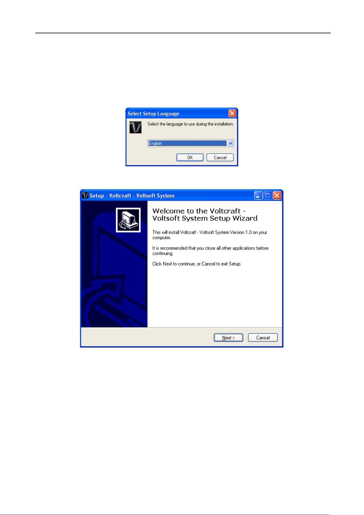
Step 1: Select the installation language
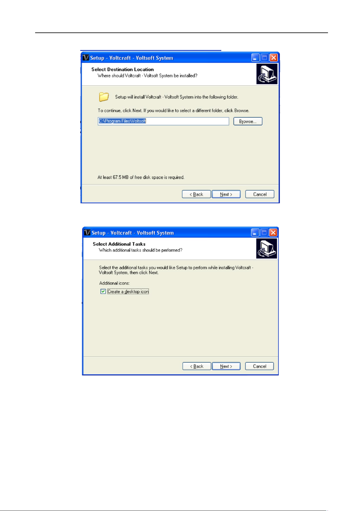
Step 2: Click “Next” for all the following steps
Page 7
Voltsoft User Manual Version 2.8
7
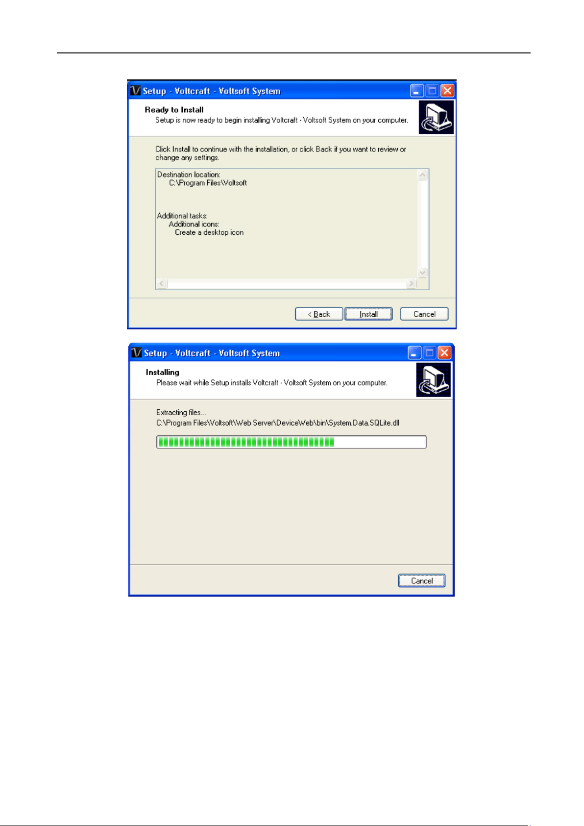
Step 3: Select Destination Location
Step 4: Tick the checkbox to create desktop icon for Voltsoft
Page 8
Voltsoft User Manual Version 2.8
8
Step 5: Click “Install”. Installation will begin.
Page 9
Voltsoft User Manual Version 2.8
9
Step 6: Click “Finish” to complete the installation
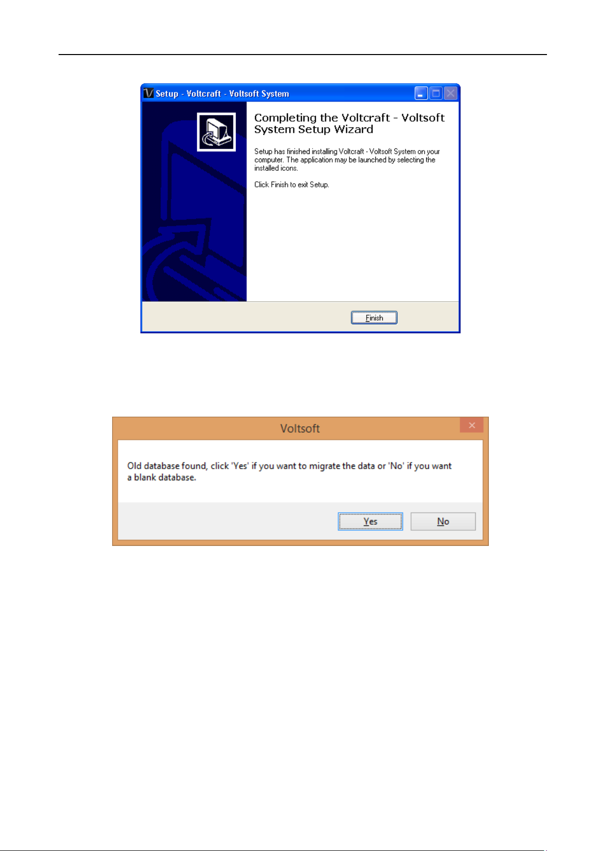
3.3 Migrate existing data
If you have an old version of Voltsoft installed, following dialog will be prompt. Click “Yes” if
you want to keep existing data or “No” if you want to have an empty database.
Page 10
Voltsoft User Manual Version 2.8
10
Standard
Professional
User Management
√
Email Management
√
General Settings
√
√
Language Preference
√ √ Email Template
√ Device Management (Add / Remove)
√ √ Custom Graph
√
Email Alert
√
3.4 Register Voltsoft
Voltsoft has two different versions: Standard and Professional. The professional version
contains more features than the standard edition.
Standard vs. Professional
Voltsoft will be installed by default as the standard version. In order to enable the professional
features, you have to purchase a software package (VoltSoft Data Logger, BN: 101333) and
enter a valid license key (which is attached on CD) to register.
To register:
1. Launch the Voltsoft Windows client
Page 11
Voltsoft User Manual Version 2.8
11
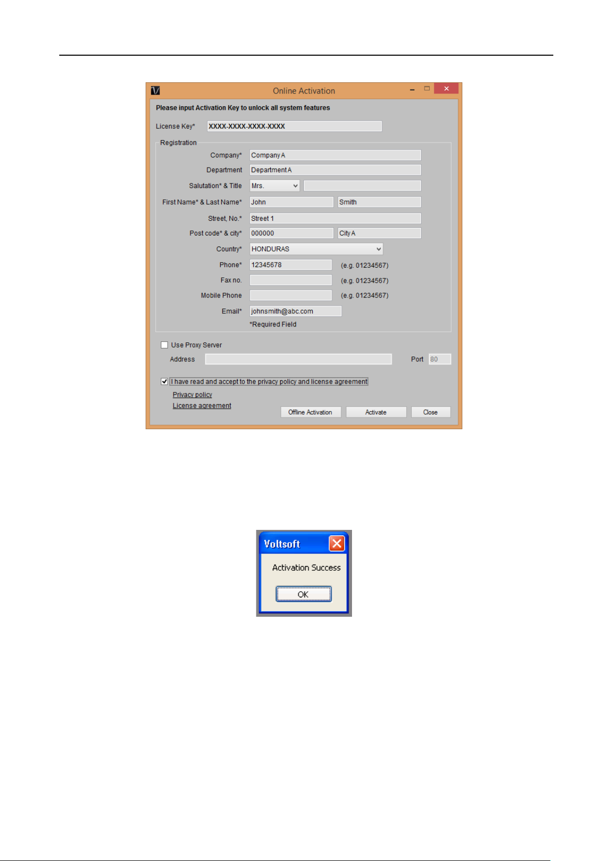
2. Click Help -> Online Activation
3. Enter a valid license key and the registration information.
4. Enter the proxy server settings if your computer accesses the Internet through a proxy
server.
5. Please read and accept our privacy policy and license agreement.
6. Click the “Activate” button to perform online activation.
7. If activation is successful the following message will be displayed:
If there is any problem during online activation, user can activate via offline activation.
1. Click the Offline Activation button and select the location for saving the activation file
(Voltsoft.config)
2. Send the Voltsoft.config to our customer service, email
3. Our customer service will return the license file (dms.config) to you.
4. Copy it to the install directory (e.g. C:\Program Files (x86)\Voltsoft)
5. Start Voltsoft again.
kundenservice@conrad.de
Page 12
Voltsoft User Manual Version 2.8
12
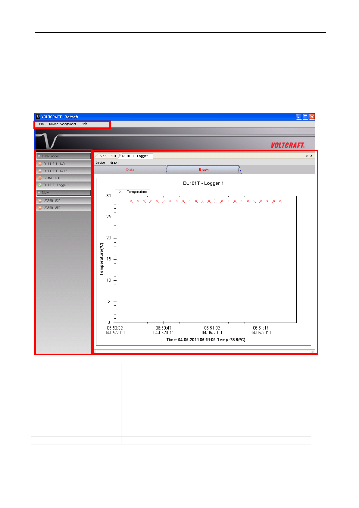
1
Main Menu Area
Users can access different functions through the main
menu.
2
Device List Area
Contains the list of devices which are already registered in
control panel area.
3
Device Control Panel
The opened device will be displayed in this area.
1 2 3
4 Standard Version
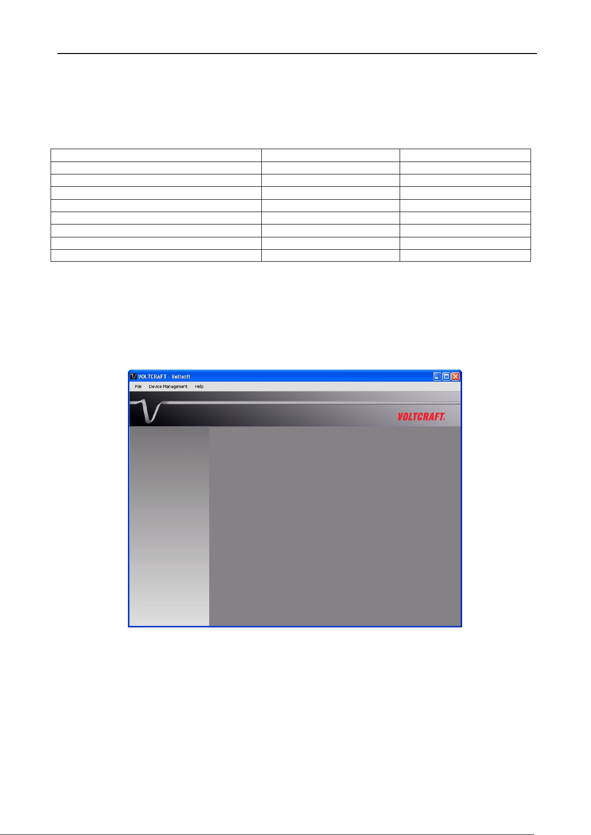
4.1 Launch the Voltsoft Windows Client
To start the application, please go to Start Menu -> All Programs -> Voltcraft -> Voltsoft Client
Main screen of the Voltsoft client is as follows:
the system.
Green icon – Indicates that the device is currently
connected to the computer
Red icon - Indicates that the device is currently not
available.
Clicking on the icon can open that device in the device
Page 13
Voltsoft User Manual Version 2.8
13
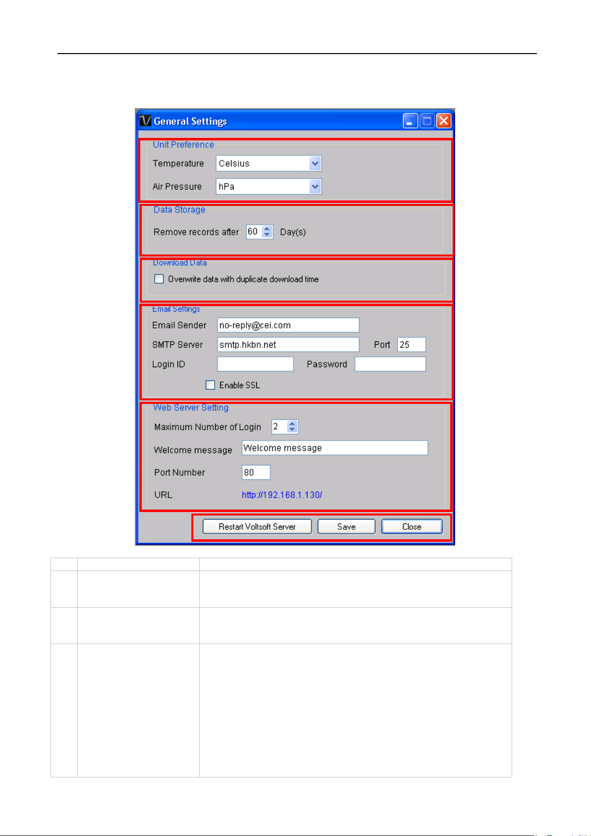
1
Unit Preference
Select the measurement unit used in Voltsoft.
2
Data Storage
In order to prevent data overload, the system will delete
to keep the device readings.
3
Download Data
If this option was checked and the system is downloading
the database, then existing data will be overwritten.
4
Email Settings
This area configures the outgoing email settings.
requires SSL encryption (i.e. Gmail)
1 2 4
5 6 3
4.2 General Settings
To launch this module, please click File->Settings.
old data automatically. User can specify the number of days
new data with measurement time, which already existed in
Email Sender – This will be the email sender of the alert
email.
SMTP Server and Port – The outgoing SMTP server name
and port number. (for Gmail, port number is 465)
Login ID and Password – The SMTP server login and
password (if required).
Enable SSL – Check this checkbox if your SMTP server
Page 14

Voltsoft User Manual Version 2.8
14 This setting is available in the professional version only.
5
Web Server Setting
This option are no longer in use.
6
Restart Voltsoft
Server
Restart the Voltsoft Server.
Save
Save and quit this module.
Close
Quit this module without saving.
Page 15
Voltsoft User Manual Version 2.8
15
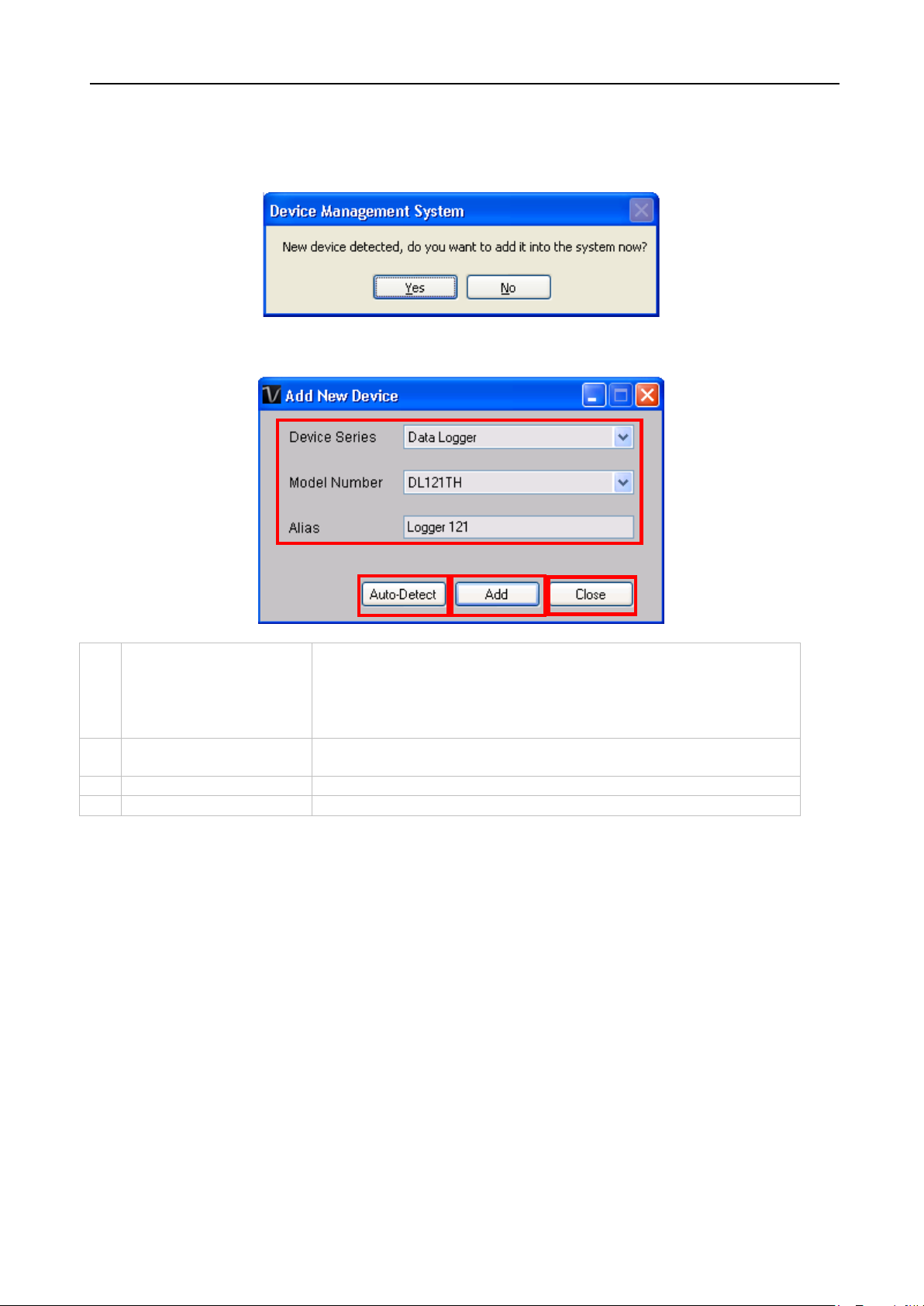
1
Select Device
To add a new device:
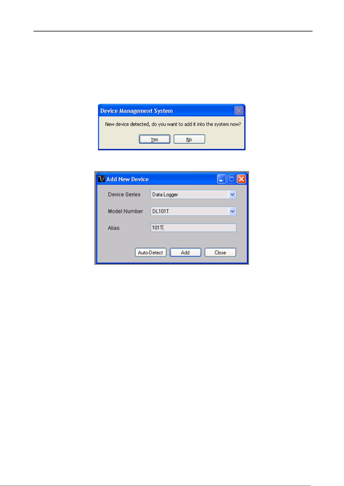
3. Enter a unique alias.
2
Auto-detect
Click this button to let the system detect if there is any
device connected but not yet registered.
3
Add
Click the Add button to confirm the addition.
4
Close
Click the Close button to close this module.
1
2 3 4
4.3 Add New Device
This module should automatically pop up when the user plugs a new device into the computer.
However, to launch this module manually, click Device Management->Add New Device.
1. Select the device series (only Data Logger available in
the current version).
2. Select model number.
Page 16
Voltsoft User Manual Version 2.8
16
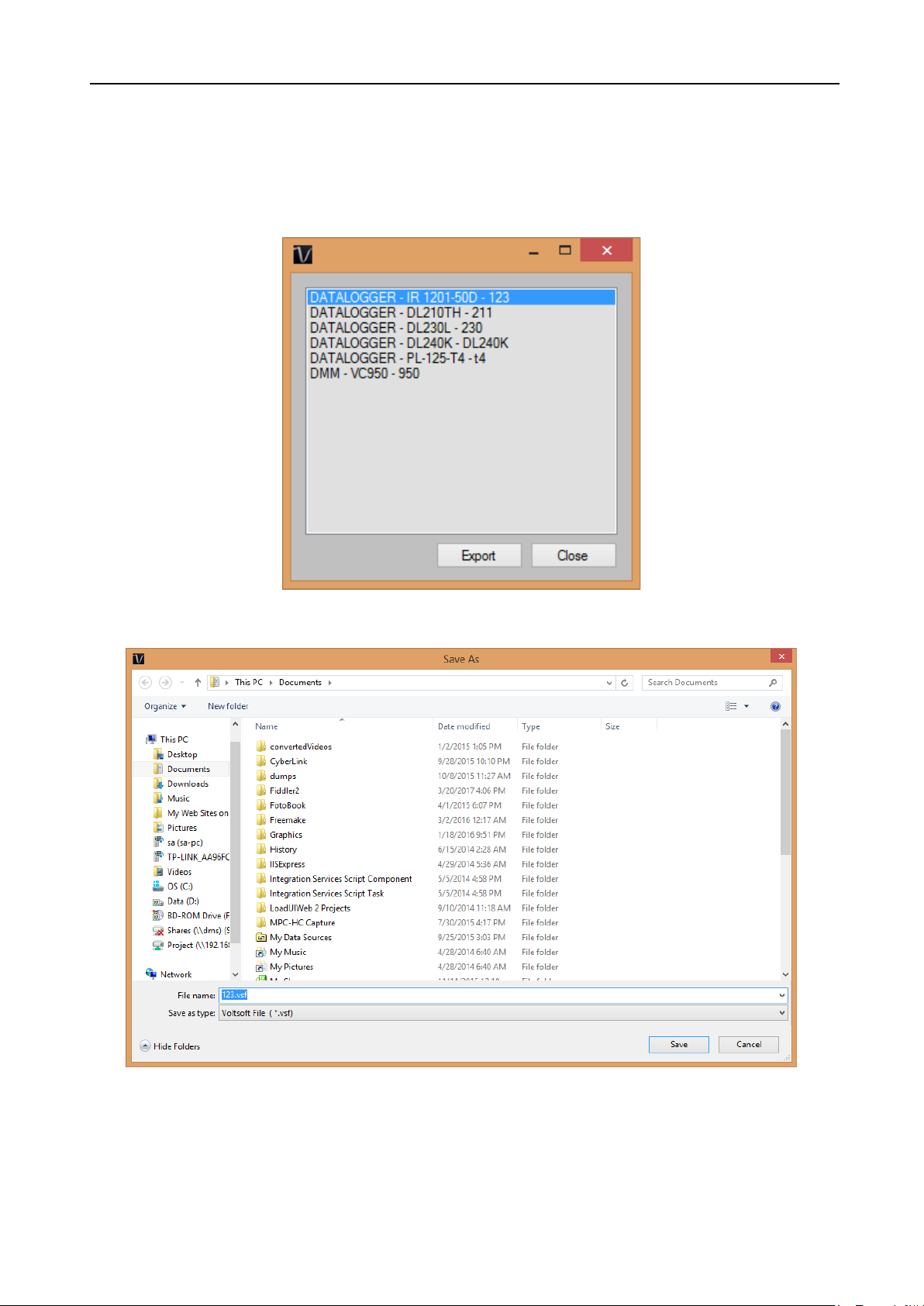
4.4 Export
This module allows the user to export device setting and readings.
Click Data > Export to launch this module.
Select the device want to export, then click the “Export” button.
Select the location for export file, then click “Save”.
Page 17
Voltsoft User Manual Version 2.8
17
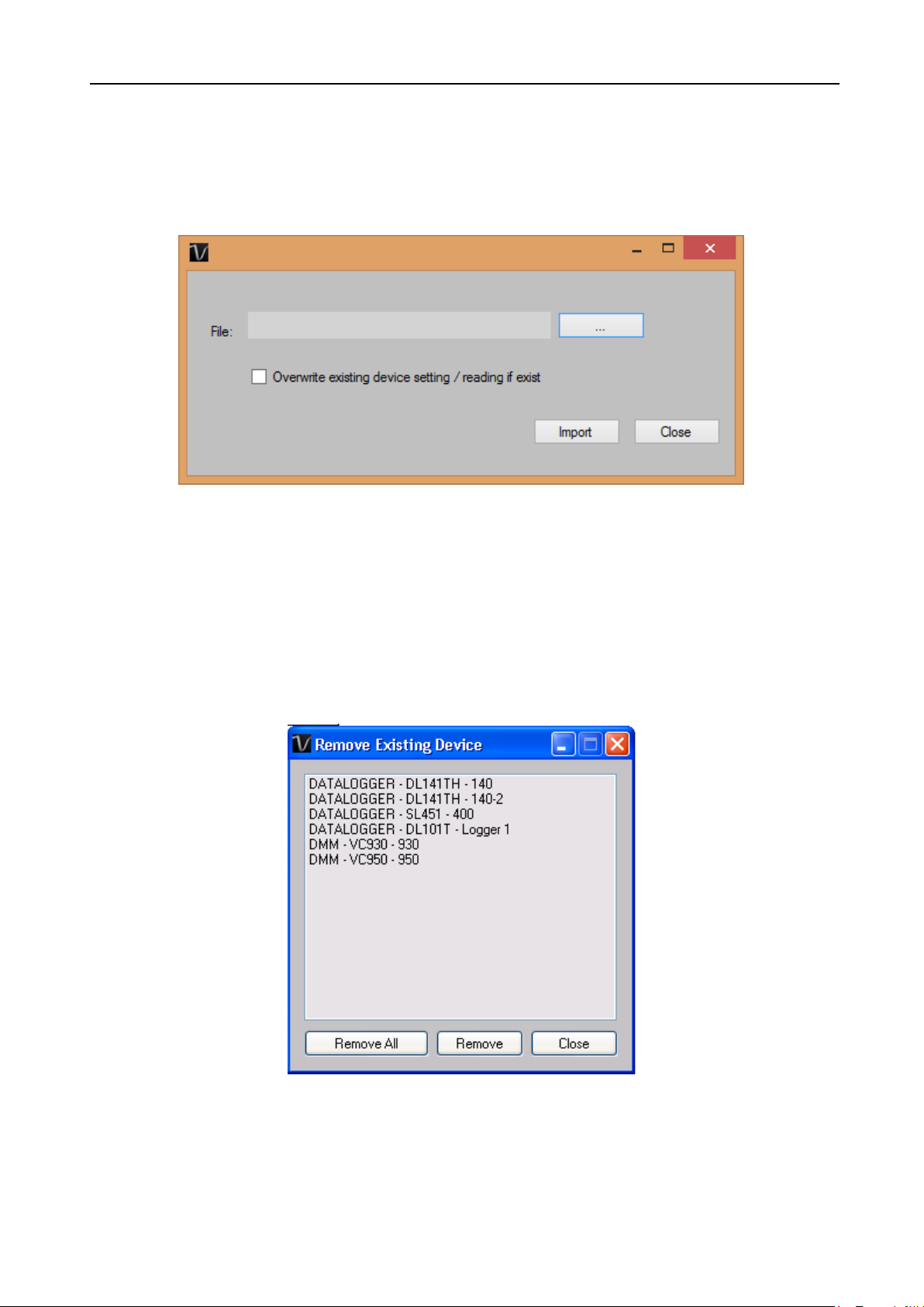
4.5 Import
This module allows the user to import device setting and readings.
Click Data > Import to launch this module.
To import device setting / readings, user need to browse the export file (The .vsf generated by
the export module), then click the import button.
If the device already exist in voltsoft and you want to overwrite the setting / readings, please
check the “Overwrite existing device setting reading if exist” option.
4.6 Remove Existing Device
This module allows the user to remove devices which are no longer in use. To launch this
module, click Device Management->Remove Existing Device.
To remove a device, click the device in the list and click the “Remove” button.
Click “Remove All” button to remove all devices at the same time.
Page 18
Voltsoft User Manual Version 2.8
18
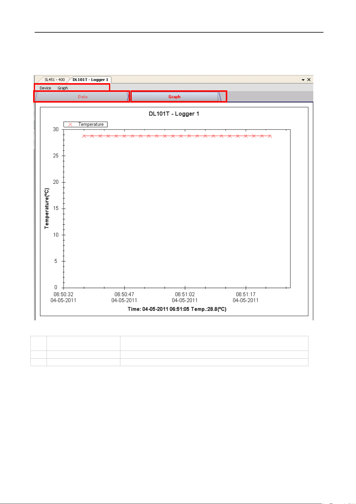
1
Device Menu Area
Each device will contain its own menu, which will be
explained in an upcoming section.
2
Data Tab
Display the selected data in list form.
3
Graph Tab
Display the selected data in a graphical format.
2 3 1
4.7 Device Control Panel
The opened device will be displayed in the device control panel area in tab format. Each tab
will contain information for one single device.
Each device tab contains:
The function of the modules may be different for different devices, therefore, they will be
discussed in individual device section.
Page 19
Voltsoft User Manual Version 2.8
19
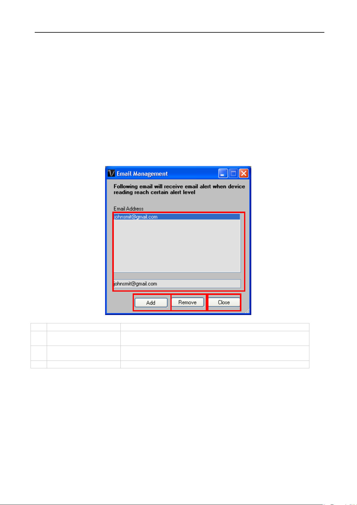
1
Email Address
The email address is configured within Voltsoft.
2
Add New Email
Input a new email address and click the Add button to add
a new email into the system.
3
Remove Email
Click on an email in the email address list and click the
Remove button to remove the email from the system.
4
Close
Close this module.
1
2 4 3
5 Professional Version
All features of the standard version and some advanced features are included in the
professional version. The following features will be available after online activation of the
professional version.
5.1 User Management
This feature no longer valid.
5.2
5.2 Email Management
This module allows the user to manage the email addresses of those who will receive email
alerts. To launch this module, click File->Email Management in the main menu.
Page 20
Voltsoft User Manual Version 2.8
20
1
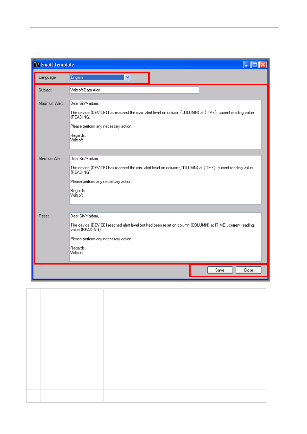
Language
Select the language of the email template.
2
Message Content
Fill in the title and content for the email template which will
3
Save
Click the Save button to save the template.
4
Close
Click the Close button to close the module.
1 2 3
5.3 Email Template
To launch this module, click Preference->Email Template.
be sent in the different cases:
Case 1: Maximum Alert
This email will be sent when a reading is higher than the
maximum alarm level.
Case 2: Minimum Alert
This email will be sent when a reading is lower than the
minimum alarm level.
Case 3: Reset Level
This email will be sent when a reading was previously at a
max/min alarm level but has returned to a normal level.
Page 21
Voltsoft User Manual Version 2.8
21
1
{DEVICE}
The device alias
2
{COLUMN}
The device reading name
3
{READING}
The device reading value
4
{TIME}
The time the event happened
Variable
The following labels are defined as variables and will be replaced when sending out.
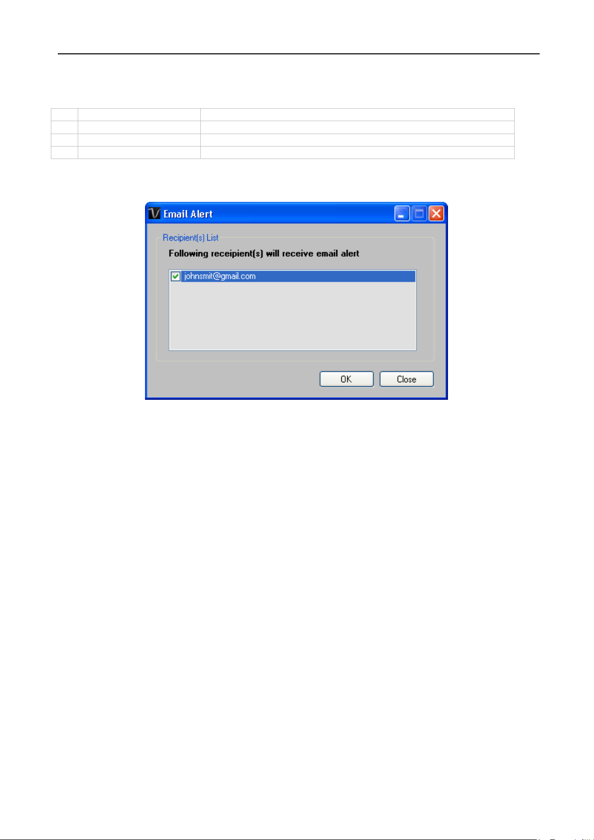
5.4 Email Alert
Voltsoft has an email alert feature, which will send out an email to the specified user when the
device reading is above or below a certain level.
The user can use this module to select who will receive the email for the specific device.
Page 22
Voltsoft User Manual Version 2.8
22
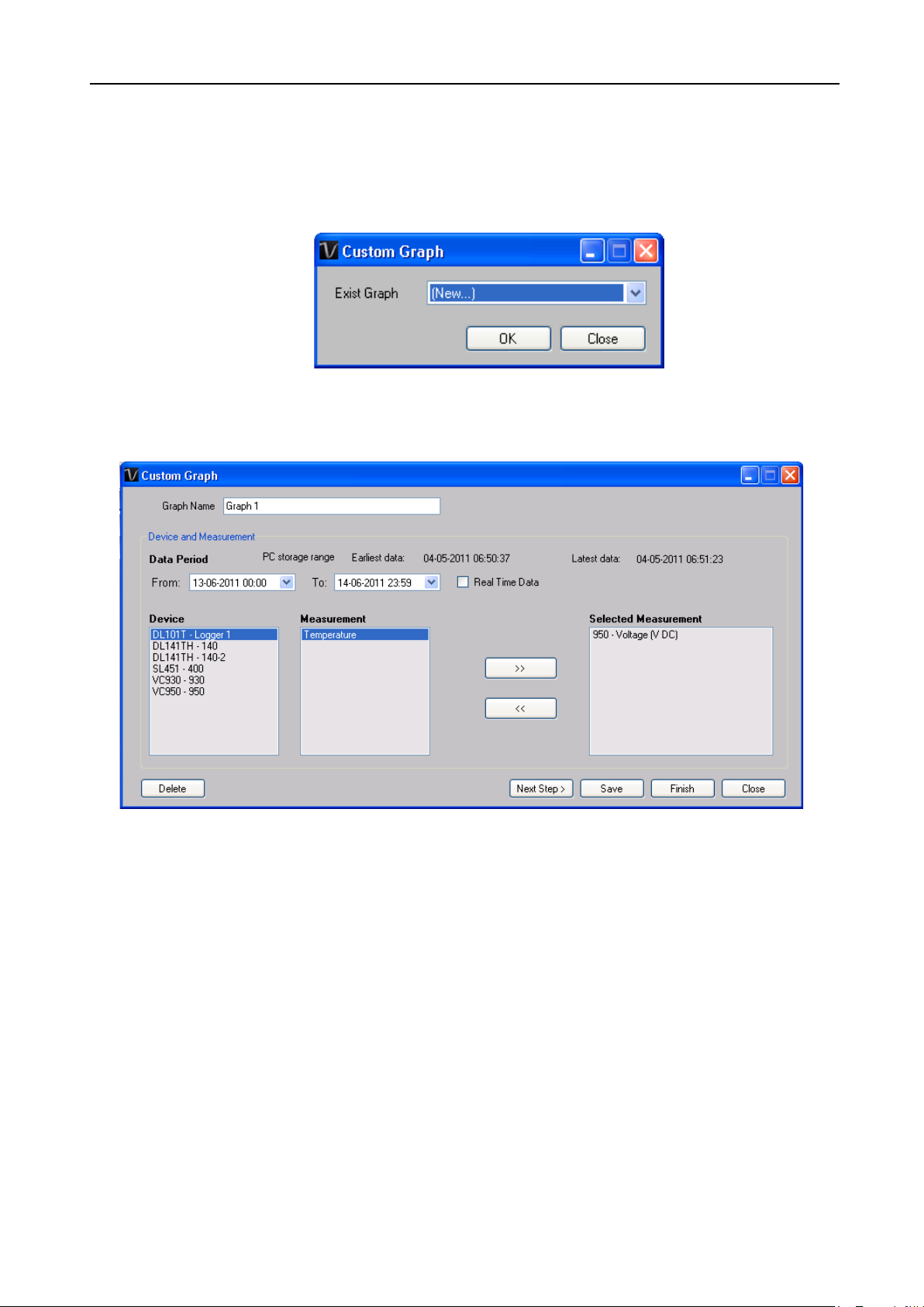
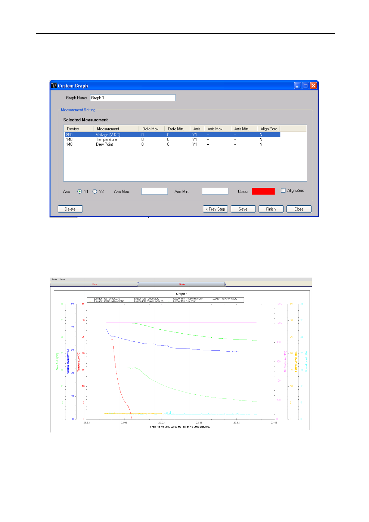
5.5 Custom Graph
Custom Graph allows the user to graph the measurement readings from more than one device.
To create a custom graph:
1. Select Device Management->Custom Graph in main menu.
2. Select New to create a new graph or select the previous saved graph. Click OK to
continue.
3. The Custom Graph detailed interface will be displayed:
Page 23
Voltsoft User Manual Version 2.8
23
4. Then the user needs to:
I. Select the data period or real-time data (only specific devices support real-time
reading).
II. Select the device and measurement column.
III. Click Next Step> to continue.
IV. For each column, the system will show the data maximum and minimum values
for the selected period.
V. For each column, the user can specify whether it is drawn in Y1 or Y2, specify the
Y-axis maximum and minimum values, the corresponding colour of the line or
align the Zero level to the same level or not.
VI. Click Finish to generate the graph.
Page 24
Voltsoft User Manual Version 2.8
24
Type
Device Name
Data Logger
DL101T
Data Logger
DL111K
Data Logger
DL121TH
Data Logger
DL131G
Data Logger
DL141TH
Data Logger
DL141TH2K
Data Logger
DL151AN
Data Logger
DL161S
Data Logger
DL181THP
Data Logger
DL191A
Data Logger
DL191V
Data Logger
DL201THM
Data Logger
DL200T
Data Logger
DL210TH
Data Logger
DL220THP
Data Logger
IR 1200-50D
Data Logger
PL-125-T2USB / PL-125-T4USB
Data Logger
SL451
DMM
VC930 / VC950
DMM
VC880 / VC650BT
DMM
VC890
EL4000
EL4000
6 Supported Devices
Voltsoft currently support following devise:
Page 25
Voltsoft User Manual Version 2.8
25
6.1 DL101T
DL101T is a data logger for storing temperature reading.
6.1.1 Add new DL101T
When Voltsoft detects a new DL101T attached, the following dialog will be popped up:
Click “Yes”, the following dialog will be displayed:
Enter a unique alias for this device, click “Add” will add the device into Voltsoft. User may also
launch this module by select Device Management->Add New Device in menu.
6.1.2 Remove DL101T
To remove DL101T, go to Device Management -> Remove Existing Device and its PC data
Storage, select the device you want to remove and click the “Remove” button.
Page 26
Voltsoft User Manual Version 2.8
26
1
Device -> Settings
This will launch the setting page of DL101T.
2
Device -> Download Data
Download reading from device.
3
Device -> Display / Plot Data
Select the time range that the device reading
should be retrieved.
4
Graph -> Plot Colour
This will launch the Plot Colour module to change
the colour of the individual lines.
5
Graph -> Background Colour
Change the background colour of the graph to
either black or white.
6
Graph -> Grid
Control whether to show / hide the grid on the
graph area.
7
Graph -> Line
Control whether to show / hide the line on the
graph area.
8
Graph -> Points Indicator
Control whether to show / hide the points
indicator.
9
Graph -> Print
Prints the generated chart.
10
Graph -> Save Image As
Save the image in the chosen file format.
11
Graph -> Zoom Out
Zoom out one level.
12
Graph -> Zoom To Fit
Undo all zoom in and out.
6.1.3 DL101T – Device Control Panel
The DL101T Device Control Panel contains follow items in menu:
Page 27
Voltsoft User Manual Version 2.8
27
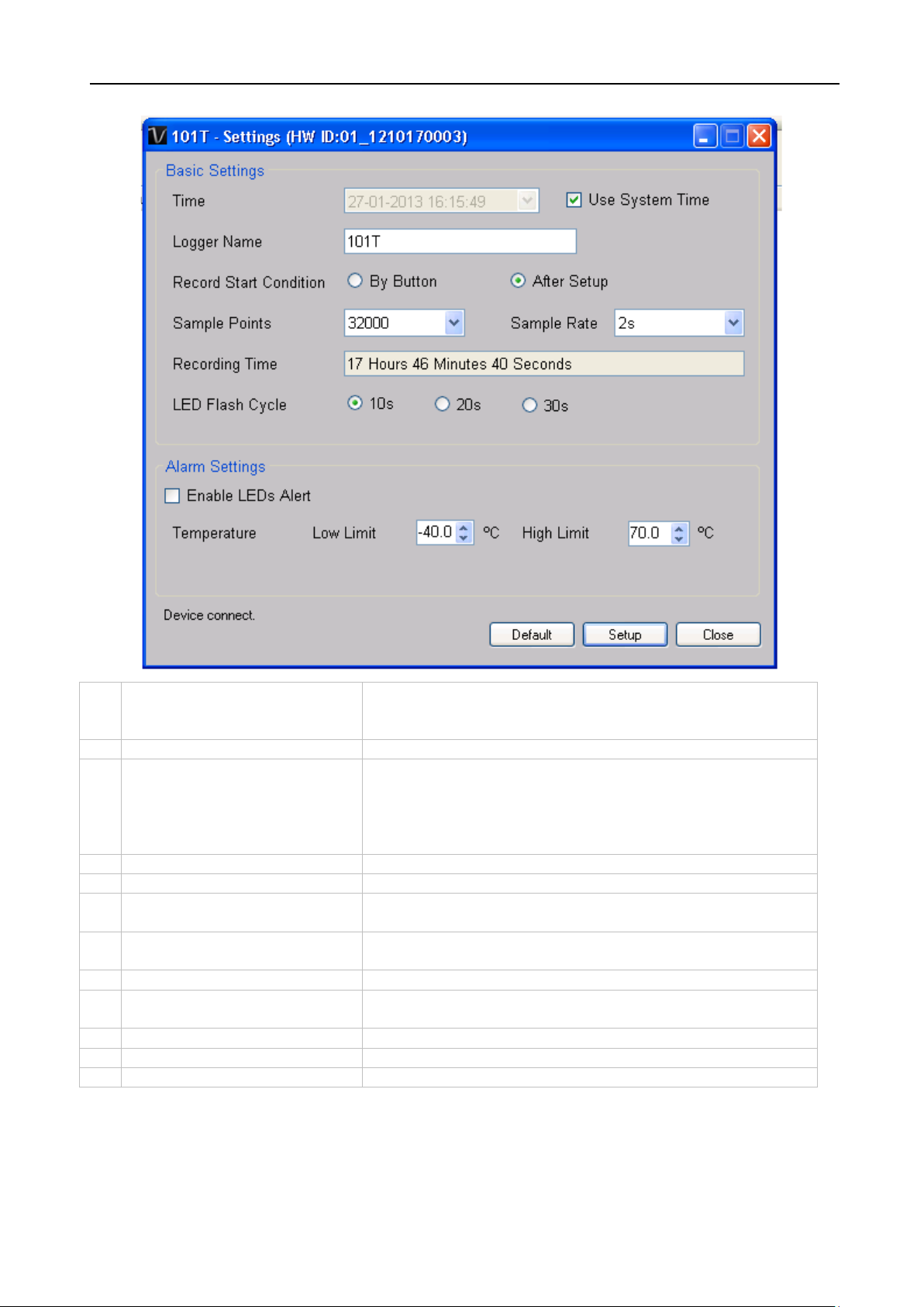
1
Time
Configure the device data time value.
date time.
2
Logger Name
Input the unique alias for that device.
3
Record Start Condition
By Button – The data logger will start recording only
immediately after setup.
4
Sample Points
Instruct the logger to take a finite number of readings.
5
Sample Rate
Instruct the logger to log readings at a specific rate.
6
Recording Time
Calculate the recording time based on the selected
sample points and sample rate.
7
LED Flash Cycle
Configure the LED flash cycle - the longer the time, the
longer the battery life.
8
Enable LED Alert
Enable / disable LED flash when the alarm is triggered.
9
Temperature Low / High
Alarm
Configure the temperature low / high alarm level.
10
Default Button
Reload the factory default settings.
11
Setup Button
Save changes.
12
Close Button
Close this interface.
6.1.4 DL101T - Settings
The user can specify a defined time or use the system
after the user pressed the red button on the device.
After Setup – The data logger will start recording
Note: Any stored data will be permanently erased when setup is finished.
Page 28
Voltsoft User Manual Version 2.8
28
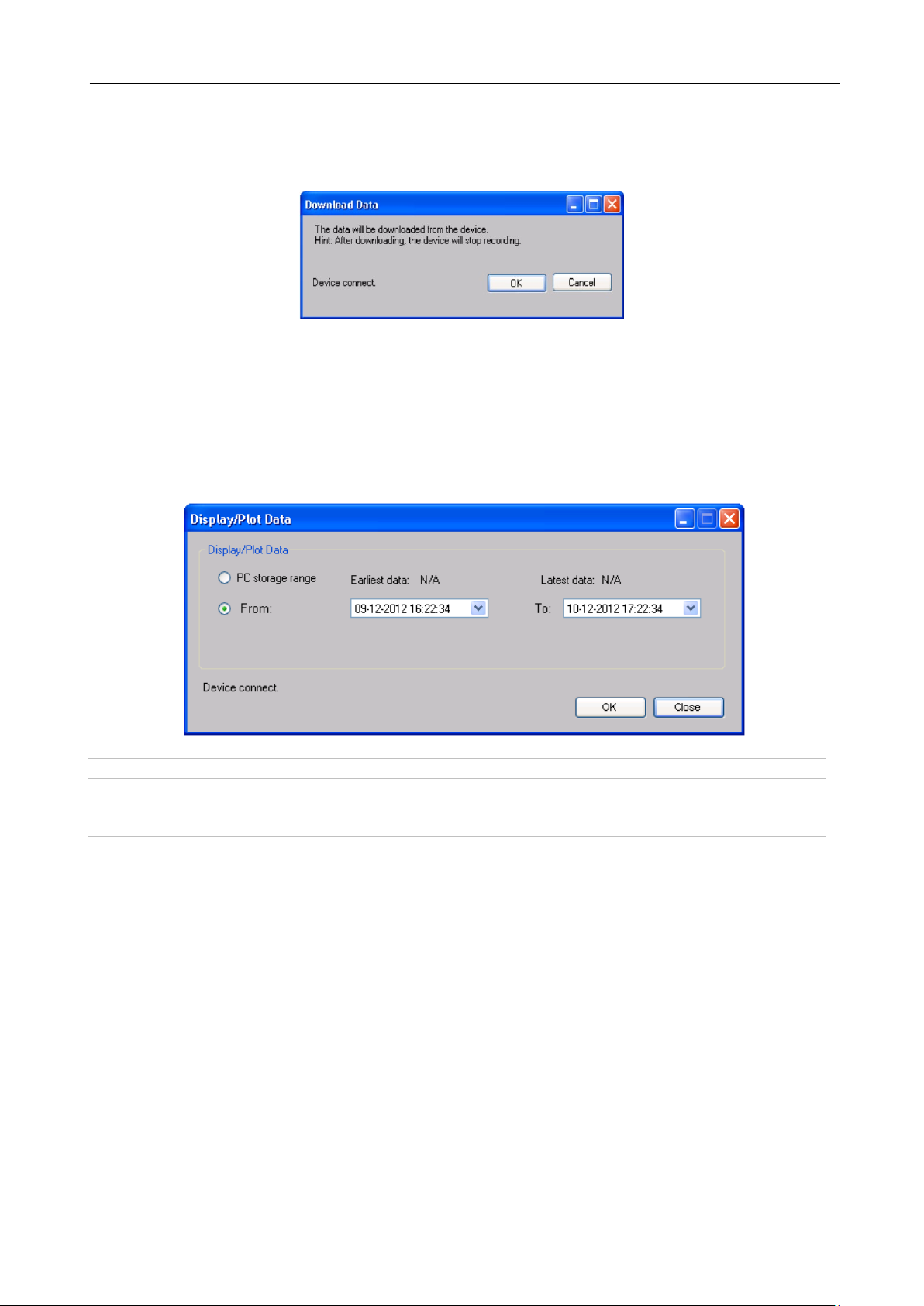
1
PC Storage Range
Download all data stored in the database.
2
Time Range
Select the data reading range.
3
OK
Click OK to accept the input and display the selected
reading in the data and graph tabs.
4
Cancel
Close this module.
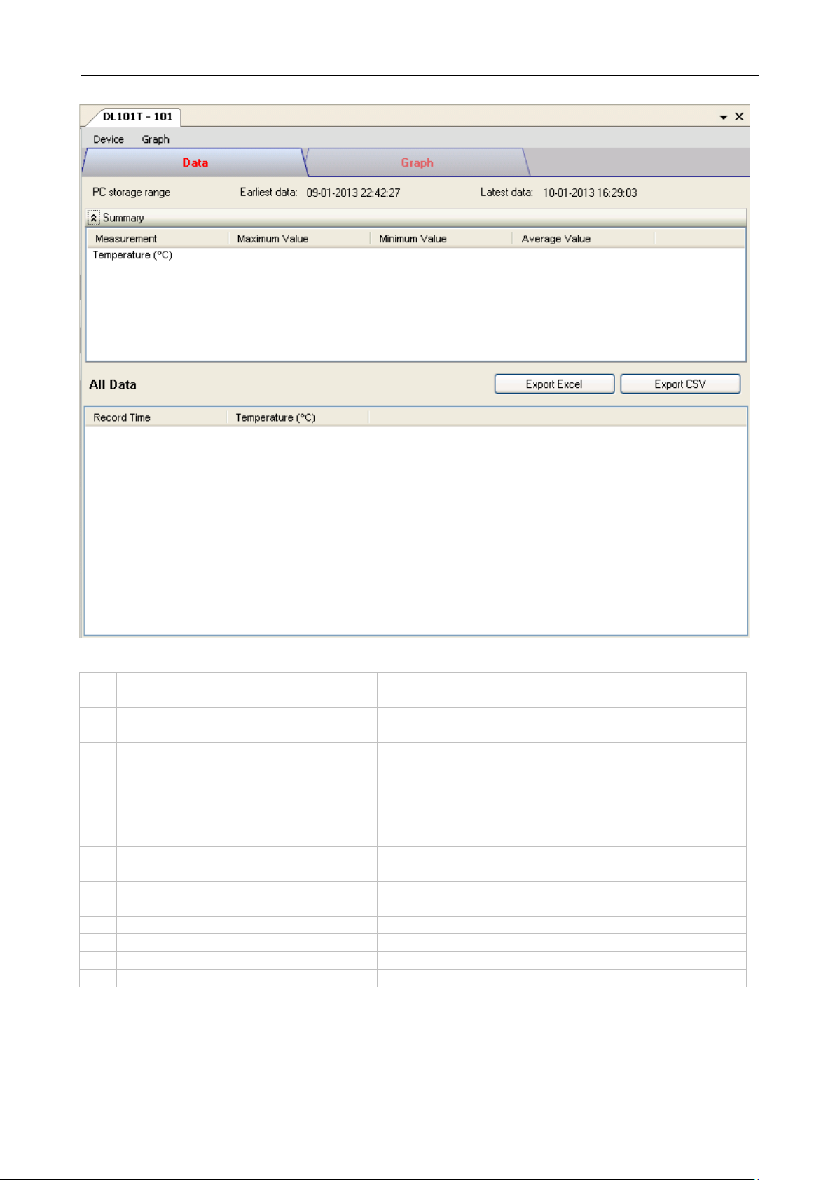
6.1.5 DL101T - Download Data
This module allows user to download the data from DL101T.
Click “OK” button to stop the recording and start downloading.
6.1.6 DL101T – Display / Plot Data
This module allows user to select a range for the device readings from the device and display
them in the data tab and graph tab.
The loading time will increase when more data is retrieved; therefore, the system will be
limited to return the first 100,000 records which meet your selection criteria.
Page 29
Voltsoft User Manual Version 2.8
29
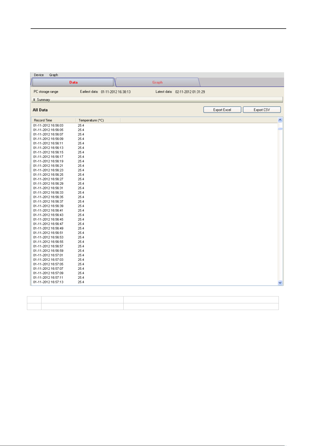
1
Export Excel
Export the reading to Excel (.xls) format.
2
Export CSV
Export the reading to Excel (.csv) format.
6.1.7 DL101T – Data View
DL101T contains one measurement (Temperature) only, its unit can be Celsius or Fahrenheit,
depending on the setting in general setting.
Page 30
Voltsoft User Manual Version 2.8
30
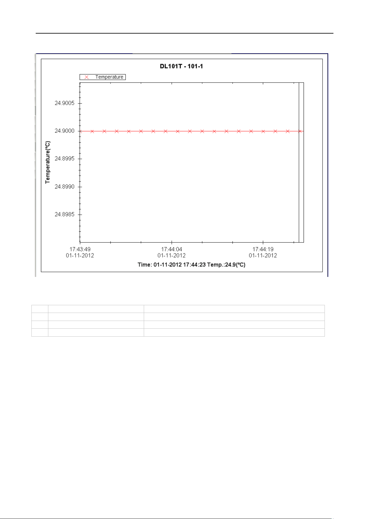
1
Mouse wheel
Zoom-in / Zoom-Out
2
Mouse click and drag
Zoom-in
3
Shift + mouse click
Pan
4
Mouse over on point
Display reading values
6.1.8 DL101T – Graph View
Our graph support following operations
Page 31

Voltsoft User Manual Version 2.8
31
6.2 DL121TH
DL121TH is a data logger for storing temperature and humidity reading.
6.2.1 Add new DL121TH
When Voltsoft detected a new DL121TH attached, the following dialog will be popped up:
Click “Yes”, the following dialog will be displayed:
Enter a unique alias for this device, click “Add” will add the device into Voltsoft. User may also
launch this module by selecting Device Management->Add New Device in menu.
6.2.2 Remove DL121TH
To remove DL121TH, go to Device Management -> Remove Existing Device and its PC data
Storage, select the device you want to remove and click the “Remove” button.
Page 32

Voltsoft User Manual Version 2.8
32
1
Device -> Settings
This will launch the setting page of DL121TH.
2
Device -> Download Data
Download reading from device.
3
Device -> Display / Plot Data
Select the time range that the device reading
should be retrieved.
4
Graph -> Plot Colour
This will launch the Plot Colour module to change
the colour of the individual lines.
5
Graph -> Background Colour
Change the background colour of the graph to
either black or white.
6
Graph -> Grid
Control whether to show / hide the grid on the
graph area.
7
Graph -> Line
Control whether to show / hide the line on the
graph area.
8
Graph -> Points Indicator
Control whether to show / hide the points
indicator.
9
Graph -> Print
Prints the generated chart.
10
Graph -> Save Image As
Save the image in the chosen file format.
11
Graph -> Zoom Out
Zoom out one level.
12
Graph -> Zoom To Fit
Undo all zoom in and out.
6.2.3 DL121TH – Device Control Panel
DL121TH contain follow items in menu:
Page 33

Voltsoft User Manual Version 2.8
33
1
Time
Configure the device data time value.
date time.
2
Logger Name
Input the unique alias for that device.
3
Record Start Condition
By Button – The data logger will start recording only
immediately after setup.
4
Sample Points
Instruct the logger to take a finite number of readings.
5
Sample Rate
Instruct the logger to log readings at a specific rate.
6
Recording Time
Calculate the recording time based on the selected
sample points and sample rate.
7
LED Flash Cycle
Configure the LED flash cycle - the longer the time, the
longer the battery life.
8
Enable LED Alert
Enable / disable LED flash when the alarm is triggered.
9
Temperature Low / High
Alarm
Configure the temperature low / high alarm level.
10
Relative humidity Low /
High Alarm
Configure the humidity low / high alarm level.
11
Default Button
Reload the factory default settings.
12
Setup Button
Save changes.
13
Close Button
Close this interface.
6.2.4 DL121TH - Settings
The user can specify a defined time or use the system
after the user presses the red button on the device.
After Setup – The data logger will start recording
Note: Any stored data will be permanently erased when setup is finished.
Page 34

Voltsoft User Manual Version 2.8
34
1
PC Storage Range
Download all data stored in the database.
2
Time Range
Select the data reading range.
3
OK
Click OK to accept the input and display the selected
reading in the data and graph tabs.
4
Cancel
Close this module.
6.2.5 DL121TH - Download Data
This module allows user to download the data from DL121TH.
Click “OK” button to stop the recording and start downloading.
6.2.6 DL121TH – Display / Plot Data
This module allows user to select a range for the device readings from the device and display
them in the data tab and graph tab.
The loading time will increase when more data is retrieved; therefore, the system will be
limited to return the first 100,000 records which meet your selection criteria.
Page 35

Voltsoft User Manual Version 2.8
35
1
Export Excel
Export the reading to Excel (.xls) format.
2
Export CSV
Export the reading to Excel (.csv) format.
6.2.7 DL121TH – Data View
DL121TH contains three measurements (Temperature, relative humidity and dew point),
template / dew point unit can be Celsius or Fahrenheit, depending on the setting in general
setting.
Page 36

Voltsoft User Manual Version 2.8
36
1
Mouse wheel
Zoom-in / Zoom-Out
2
Mouse click and drag
Zoom-in
3
Shift + mouse click
Pan
4
Mouse over on point
Display reading values
6.2.8 DL121TH – Graph View
Our graph supports the following operations
Page 37

Voltsoft User Manual Version 2.8
37
6.3 DL131G
DL131G is a data logger for storing vibration reading. DL131G supports real time and real
time Fast Fourier Transform (FFT) measurement.
6.3.1 Add new DL131G
When Voltsoft detected a new DL131G attached, the following dialog will be popped up:
Click “Yes”, following dialog will be displayed:
Enter a unique alias for this device, click “Add” will add the device into Voltsoft. User may also
launch this module by selecting Device Management->Add New Device in menu.
6.3.2 Remove DL131G
To remove DL131G, go to Device Management -> Remove Existing Device and its PC data
Storage, select the device you want to remove and click the “Remove” button.
Page 38

Voltsoft User Manual Version 2.8
38
1
Device -> Settings
This will launch the setting page of DL131G.
2
Device -> Stop
Stop the real time data download.
3
Device -> Download Data
Download reading from device.
4
Device -> Display / Plot Data
Select the time range that the device reading
should be retrieved.
5
Graph -> Plot Colour
This will launch the Plot Colour module to change
the colour of the individual lines.
6
Graph -> Background Colour
Change the background colour of the graph to
either black or white.
7
Graph -> Grid
Control whether to show / hide the grid on the
graph area.
8
Graph -> Line
Control whether to show / hide the line on the
graph area.
9
Graph -> Points Indicator
Control whether to show / hide the points
indicator.
10
Graph -> Print
Prints the generated chart.
11
Graph -> Save Image As
Save the image in the chosen file format.
12
Graph -> Zoom Out
Zoom out one level.
13
Graph -> Zoom To Fit
Undo all zoom in and out.
14
Graph -> View All Data
Zoom out the graph to view all data.
6.3.3 DL131G – Device Control Panel
The DL131G Device Control Panel contains follow items in menu:
Page 39

Voltsoft User Manual Version 2.8
39
1
Time
Configure the device data time value.
time.
2
Logger Name
Input the unique alias for that device.
3
Sample Rate
Instruct the data logger to log readings at a specific
rate.
4
LED Flash RateCycle
Configure the LED flash cycle - the longer the time, the
longer the battery life.
5
Record Start Condition
By Button – The data logger will start recording only
immediately after setup.
6
Motion Detection Threshold
The Motion Detection Threshold Setup filed allows the
DATALOGGER will work.
7
Recording Mode
The DATA LOGGER Record Mode can be set as Normal
and Motion Detection.
8
Default Button
Load the factory default settings.
9
Setup Button
Save changes.
10
Close Button
Close this interface.
6.3.4 DL131G – Settings
Setup
User can specify a defined time or use the system date
after the user pressed the red button on
the device.
After Setup – The data logger will start recording
user to set the acceleration detection threshold.Once
the acceleration value is over the threshold,the
Page 40

Voltsoft User Manual Version 2.8
40
1
PC Storage Range
Download all data stored in the database.
2
Time Range
Select the data reading range.
3
Real Time Data
Download real time data, will only enable if the device
in real time mode.
4
Real Time FFT
Read real-time spectral data for FFT analysis.
5
OK
Click OK to accept the input and display the selected
reading in the data and graph tabs.
6
Cancel
Close this module.
6.3.5 DL131G - Download Data
This module allows user to download the data from DL131G.
Click “OK” button to stop the recording and start downloading.
6.3.6 DL131G – Display / Plot Data
This module allows user to select a range for the device readings from the device and display
them in the data tab and graph tab.
The loading time will increase when more data is retrieved; therefore, the system will be
limited to return the first 100,000 records which meet your selection criteria.
Page 41

Voltsoft User Manual Version 2.8
41
1
Export Excel
Export the reading to Excel (.xls) format.
2
Export CSV
Export the reading to Excel (.csv) format.
6.3.7 DL131G – Data View
DL131G contains four measurements (X Value, Y Value, Z Value and Vector Sum).
Page 42

Voltsoft User Manual Version 2.8
42
1
Mouse wheel
Zoom-in / Zoom-Out
2
Mouse click and drag
Zoom-in
3
Shift + mouse click
Pan
4
Mouse over on point
Display reading values
6.3.8 DL131G – Graph View
Our graph support following operations
Page 43

Voltsoft User Manual Version 2.8
43
6.3.9 DL131G – Real Time FFT
The logger will enter real time FFT mode when select “Real Time FFT” in “Display / Plot Data”.
In FFT mode, there is two options for displaying data: Time Domain and Frequency Domain.
Time Domain:
In time domain mode, total 128 reading will be download at any specific period of time.
Page 44

Voltsoft User Manual Version 2.8
44
Frequency Domain:
In frequency domain mode, the 128 reading downloaded will be calculate and transform to 256
readings to display.
Page 45

Voltsoft User Manual Version 2.8
45
6.4 DL141TH
DL141TH is a data logger for storing temperature and humidity readings.
6.4.1 Add new DL141TH
When Voltsoft detected a new DL141TH attached, the following dialog will be popped up:
Click “Yes”, the following dialog will be displayed:
Enter a unique alias for this device, click “Add” will add the device into Voltsoft. User may also
launch this module by selecting Device Management->Add New Device in menu.
6.4.2 Remove DL141TH
To remove DL141TH, go to Device Management -> Remove Existing Device and its PC data
Storage, select the device you want to remove and click the “Remove” button.
Page 46

Voltsoft User Manual Version 2.8
46
1
Device -> Settings
This will launch the setting page of DL141TH.
2
Device -> Download Data
Download reading from device.
3
Device -> Display / Plot Data
Select the time range that the device reading
should be retrieved.
4
Graph -> Plot Colour
This will launch the Plot Colour module to change
the colour of the individual lines.
5
Graph -> Background Colour
Change the background colour of the graph to
either black or white.
6
Graph -> Grid
Control whether to show / hide the grid on the
graph area.
7
Graph -> Line
Control whether to show / hide the line on the
graph area.
8
Graph -> Points Indicator
Control whether to show / hide the points
indicator.
9
Graph -> Print
Prints the generated chart.
10
Graph -> Save Image As
Save the image in the chosen file format.
11
Graph -> Zoom Out
Zoom out one level.
12
Graph -> Zoom To Fit
Undo all zoom in and out.
6.4.3 DL141TH – Device Control Panel
The DL141TH Device Control Panel contains the following items in menu:
Page 47

Voltsoft User Manual Version 2.8
47
1
Device Time
Configure the device data time value.
time.
2
Logger Name
Enter the unique alias for that device.
3
Record Start Condition
By Button – The data logger will start recording only
immediately after setup.
Sample Rate
Instruct the data logger to log readings at a specific
on the right.
5
Recording Time
Calculate the recording time based on the selected
sample points and sample rate.
6
LED Flash Cycle
Configure the LED flash cycle - the longer the time, the
longer the battery life.
7
Recording
Instruct the data logger to continue logging data,
memory is full.
8
Enable LED Alert
Enable / disable LED flash when the alarm is triggered.
9
Temperature Low / High
Alarm
Configure the temperature low / high alarm level.
10
Humidity Low / High Alarm
Configure the humidity low / high alarm level.
11
Default Button
Reload the factory default settings.
12
Setup Button
Save changes.
13
Close Button
Close this interface.
6.4.4 DL141TH – Settings
User can specify a defined time or use the system date
after the user presses the red button on
the device.
After Setup – The data logger will start recording
rate. The user can input specific data in the edit box on
the left and select the time unit using the combo box
recording over the earlier data (Circulating Record), or
to stop logging (No Circulating) when the data logger
Page 48

Voltsoft User Manual Version 2.8
48
1
PC Storage Range
Download all data stored in the database.
2
Time Range
Select the data reading range.
3
OK
Click OK to accept the input and display the selected
reading in the data and graph tabs.
4
Cancel
Close this module.
6.4.5 DL141TH - Download Data
This module allows user to download the data from DL141TH.
Click “OK” button to stop the recording and start downloading.
6.4.6 DL141TH – Display / Plot Data
This module allows user to select a range for the device readings from the device and display
them in the data tab and graph tab.
The loading time will increase when more data is retrieved; therefore, the system will be
limited to return the first 100,000 records which meet your selection criteria.
Page 49

Voltsoft User Manual Version 2.8
49
1
Export Excel
Export the reading to Excel (.xls) format.
2
Export CSV
Export the reading to Excel (.csv) format.
6.4.7 DL141TH – Data View
DL141TH contains three measurements (Temperature, relative humidity and dew point),
template / dew point unit can be Celsius or Fahrenheit, depending on the setting in general
setting.
Page 50

Voltsoft User Manual Version 2.8
50
1
Mouse wheel
Zoom-in / Zoom-Out
2
Mouse click and drag
Zoom-in
3
Shift + mouse click
Pan
4
Mouse over on point
Display reading values
6.4.8 DL141TH – Graph View
Our graph supports the following operations
Page 51

Voltsoft User Manual Version 2.8
51
6.5 DL161S
DL161S is a data logger for storing sound level reading. DL161S supports real time
measurement.
6.5.1 Add new DL161S
When Voltsoft detected a new DL161S attached, the following dialog will be popped up:
Click “Yes”, following dialog will be displayed:
Enter a unique alias for this device, click “Add” will add the device into Voltsoft. User may also
launch this module by selecting Device Management->Add New Device in menu.
6.5.2 Remove DL161S
To remove DL161S, go to Device Management -> Remove Existing Device and its PC data
Storage, select the device you want to remove and click the “Remove” button.
Page 52

Voltsoft User Manual Version 2.8
52
1
Device -> Settings
This will launch the setting page of DL161S.
2
Device -> Stop
Stop the real time data download.
3
Device -> Download Data
Download reading from device.
4
Device -> Display / Plot Data
Select the time range that the device reading
should be retrieved.
5
Device -> Email Alert
This will launch the email alert module.
(Available in Professional version only)
6
Device -> Calibration
Launch the calibration module.
7
Graph -> Plot Colour
This will launch the Plot Colour module to change
the colour of the individual lines.
8
Graph -> Background Colour
Change the background colour of the graph to
either black or white.
9
Graph -> Grid
Control whether to show / hide the grid on the
graph area.
10
Graph -> Line
Control whether to show / hide the line on the
graph area.
11
Graph -> Points Indicator
Control whether to show / hide the points
indicator.
12
Graph -> Print
Prints the generated chart.
13
Graph -> Save Image As
Save the image in the chosen file format.
14
Graph -> Zoom Out
Zoom out one level.
15
Graph -> Zoom To Fit
Undo all zoom in and out.
16
Graph -> View All Data
Zoom out the graph to view all data.
6.5.3 DL161S – Device Control Panel
The DL161S Device Control Panel contains follow items in menu:
Page 53

Voltsoft User Manual Version 2.8
53
1
Time
Configure the device data time value.
time.
2
Logger Name
Input the unique alias for that device.
3
Sound Unit
The sound unit can be dBA or dBC.
4
Measuring speed
The measuring speed can be Fast or Slow.
5
Record Start Condition
By Button – The data logger will start recording only
immediately after setup.
6
Sample Rate
Instruct the data logger to log readings at a specific
rate.
7
Sample Points
Configure the data logger sample points.
8
Infinite
For real time mode only, the download will not stop
until the user stopped the download.
9
Recording Time
Calculate the recording time based on the selected
sample points and sample rate.
10
LED Flash Cycle
Configure the LED flash cycle - the longer the time, the
longer the battery life.
11
Logger Mode
Manual – The data logger will start recording only
immediately after setup.
12
Storage Setup
Storage can be Store or Real Time.
Store – The data will be stored in offline mode.
6.5.4 DL161S – Settings
User can specify a defined time or use the system date
after the user pressed the red button on
the device.
After Setup – The data logger will start recording
after the user presses the red button on
the device.
Instant – The data logger will start recording
Page 54

Voltsoft User Manual Version 2.8
54
Real Time – The data will be stored in real time
mode.
13
LED Flash for High / Low
Alarm
Enable / disable LED flash when the alarm is triggered.
14
Low / High Alarm for dBA
Configure the sound level (at unit dBA) for the low /
high alarm level.
15
Low / High Alarm for dBC
Configure the sound level (at unit dBC) for the low /
high alarm level.
16
Default Button
Load the factory default settings.
17
Setup Button
Save changes.
18
Close Button
Close this interface.
1
PC Storage Range
Download all data stored in the database.
2
Time Range
Select the data reading range.
3
Real Time Data
Download real time data, will only enable if the device
in real time mode.
4
OK
Click OK to accept the input and display the selected
reading in the data and graph tabs.
5
Cancel
Close this module.
6.5.5 DL161S - Download Data
This module allows user to download the data from DL161S.
Click “OK” button to stop the recording and start downloading.
6.5.6 DL161S – Display / Plot Data
This module allows user to select a range for the device readings from the device and display
them in the data tab and graph tab.
The loading time will increase when more data is retrieved; therefore, the system will be
limited to return the first 100,000 records which meet your selection criteria.
Page 55

Voltsoft User Manual Version 2.8
55
1
Export Excel
Export the reading to Excel (.xls) format.
2
Export CSV
Export the reading to Excel (.csv) format.
6.5.7 DL161S – Data View
DL161S contains two measurements (sound level in dBA and sound level in dBC), the device
can record only one measurement at any specific unit of time (Control in Setting).
Page 56

Voltsoft User Manual Version 2.8
56
1
Mouse wheel
Zoom-in / Zoom-Out
2
Mouse click and drag
Zoom-in
3
Shift + mouse click
Pan
4
Mouse over on point
Display reading values
6.5.8 DL161S – Graph View
Our graph support following operations
Page 57

Voltsoft User Manual Version 2.8
57
6.5.9 DL161S – Email Alert
As DL161S supports real time measurement, therefore, it has an email alert feature, which will
send out an email to the specified user when the device reading is above or below a certain
level. The alert level can be configured in Setting.
User can use this module to select who will receive the email for the specific device.
6.5.10 DL161S – Calibration
DL161S provides an interface to the user for sound level calibration. The calibration
adjustment value is allowed between -12.5 dB and 12.5 dB.
Enter the value and click “OK” to set the value.
Page 58

Voltsoft User Manual Version 2.8
58
6.6 DL141TH2K
DL141TH2K is a data logger for storing light level.
6.6.1 Add new DL141TH2K
When Voltsoft detects a new DL141TH2K attached, the following dialog will be popped up:
Click “Yes”, the following dialog will be displayed:
Enter a unique alias for this device, click “Add” will add the device into Voltsoft. User may also
launch this module by select Device Management->Add New Device in menu.
6.6.2 Remove DL141TH2K
To remove DL141TH2K, go to Device Management -> Remove Existing Device and its PC data
Storage, select the device you want to remove and click the “Remove” button.
Page 59

Voltsoft User Manual Version 2.8
59
1
Device -> Settings
This will launch the setting page of DL141TH2K.
2
Device -> Download Data
Download reading from device.
3
Device -> Display / Plot Data
Select the time range that the device reading
should be retrieved.
4
Graph -> Plot Colour
This will launch the Plot Colour module to change
the colour of the individual lines.
5
Graph -> Background Colour
Change the background colour of the graph to
either black or white.
6
Graph -> Grid
Control whether to show / hide the grid on the
graph area.
7
Graph -> Line
Control whether to show / hide the line on the
graph area.
8
Graph -> Points Indicator
Control whether to show / hide the points
indicator.
9
Graph -> Print
Prints the generated chart.
10
Graph -> Save Image As
Save the image in the chosen file format.
11
Graph -> Zoom Out
Zoom out one level.
12
Graph -> Zoom To Fit
Undo all zoom in and out.
6.6.3 DL141TH2K– Device Control Panel
The DL141TH2K Device Control Panel contains follow items in menu:
Page 60

Voltsoft User Manual Version 2.8
60
1
Time
Configure the device data time value.
date time.
2
Logger Name
Input the unique alias for that device.
3
Record Start Condition
By Button – The data logger will start recording only
immediately after setup.
4
Sample Points
Instruct the logger to take a finite number of readings.
5
Sample Rate
Instruct the logger to log readings at a specific rate.
6
Recording Time
Calculate the recording time based on the selected
sample points and sample rate.
7
LED Flash Cycle
Configure the LED flash cycle - the longer the time, the
longer the battery life.
8
Enable LED Alert
Enable / disable LED flash when the alarm is triggered.
9
Low / High Alarm
Configure the low / high alarm level.
10
Default Button
Reload the factory default settings.
11
Setup Button
Save changes.
12
Close Button
Close this interface.
6.6.4 DT141TH2K - Settings
The user can specify a defined time or use the system
after the user pressed the red button on the device.
After Setup – The data logger will start recording
Note: Any stored data will be permanently erased when setup is finished.
Page 61

Voltsoft User Manual Version 2.8
61
1
PC Storage Range
Download all data stored in the database.
2
Time Range
Select the data reading range.
3
Measurement
User can select Celsius or Fahrenheit record to
download.
4
OK
Click OK to accept the input and display the selected
reading in the data and graph tabs.
5
Cancel
Close this module.
6.6.5 DL141TH2K - Download Data
This module allows user to download the data from DL141TH2K.
Click “OK” button to stop the recording and start downloading.
6.6.6 DL141TH2K– Display / Plot Data
This module allows user to select a range for the device readings from the device and display
them in the data tab and graph tab.
The loading time will increase when more data is retrieved; therefore, the system will be
limited to return the first 100,000 records which meet your selection criteria.
Page 62

Voltsoft User Manual Version 2.8
62
1
Export Excel
Export the reading to Excel (.xls) format.
2
Export CSV
Export the reading to Excel (.csv) format.
6.6.7 DL141TH2K – Data View
DL141TH2K contains total four measurements:T1, T2, Temperature and Relative humidity.
Page 63

Voltsoft User Manual Version 2.8
63
1
Mouse wheel
Zoom-in / Zoom-Out
2
Mouse click and drag
Zoom-in
3
Shift + mouse click
Pan
4
Mouse over on point
Display reading values
6.6.8 DL141TH2K– Graph View
Our graph support following operations
Page 64

Voltsoft User Manual Version 2.8
64
6.7 DL181THP
DL181THP is a data logger for storing temperature, humidity and air pressure reading.
6.7.1 Add new DL181THP
When Voltsoft detected a new DL181THP attached, the following dialog will be popped up:
Click “Yes”, the following dialog will be displayed:
Enter a unique alias for this device, click “Add” will add the device into Voltsoft. User may also
launch this module by selecting Device Management->Add New Device in menu.
6.7.2 Remove DL181THP
To remove DL181THP, go to Device Management -> Remove Existing Device and its PC data
Storage, select the device you want to remove and click the “Remove” button.
Page 65

Voltsoft User Manual Version 2.8
65
1
Device -> Settings
This will launch the setting page of DL181THP.
2
Device -> Download Data
Download reading from device.
3
Device -> Display / Plot Data
Select the time range that the device reading
should be retrieved.
4
Graph -> Plot Colour
This will launch the Plot Colour module to change
the colour of the individual lines.
5
Graph -> Background Colour
Change the background colour of the graph to
either black or white.
6
Graph -> Grid
Control whether to show / hide the grid on the
graph area.
7
Graph -> Line
Control whether to show / hide the line on the
graph area.
8
Graph -> Points Indicator
Control whether to show / hide the points
indicator.
9
Graph -> Print
Prints the generated chart.
10
Graph -> Save Image As
Save the image in the chosen file format.
11
Graph -> Zoom Out
Zoom out one level.
12
Graph -> Zoom To Fit
Undo all zoom in and out.
6.7.3 DL181THP – Device Control Panel
The DL181THP Device Control Panel contains the following items in menu:
Page 66

Voltsoft User Manual Version 2.8
66
1
Time
Configure the device data time value.
date time.
2
Logger Name
Input the unique alias for that device.
3
Record Start Condition
By Button – The data logger will start recording only
immediately after setup.
4
Sample Rate
Instruct the data logger to log readings at a specific
rate.
5
Sample Points
Configure the data logger sample points.
6
Recording Time
Calculate the recording time based on the selected
sample points and sample rate.
7
Altitude
Allows user to set the current altitude.
8
Record LED Flash
Configure the LED flash cycle - the longer the time, the
longer the battery life.
9
Enable LED Alert
Enable / disable LED flash when the alarm is triggered.
10
Temperature Low / High
Alarm
Configure the temperature low / high alarm level
11
Humidity Low / High Alarm
Configure the humidity low / high alarm level
12
Air Pressure Low / High
Alarm
Configure the air pressure low / high alarm level
13
Default Button
Load the factory default settings.
14
Setup Button
Save changes.
15
Close Button
Close this interface.
6.7.4 DL181THP – Settings
The user can specify a defined time or use the system
after the user presses the red button on
the device.
After Setup – The data logger will start recording
Page 67

Voltsoft User Manual Version 2.8
67
1
PC Storage Range
Download all data stored in the database.
2
Time Range
Select the data reading range.
3
OK
Click OK to accept the input and display the selected
reading in the data and graph tabs.
4
Cancel
Close this module.
6.7.5 DL181THP - Download Data
This module allows user to download the data from DL181THP.
Click “OK” button to stop the recording and start downloading.
6.7.6 DL181THP – Display / Plot Data
This module allows user to select a range for the device readings from the device and display
them in the data tab and graph tab.
The loading time will increase when more data is retrieved; therefore, the system will be
limited to return the first 100,000 records which meet your selection criteria.
Page 68

Voltsoft User Manual Version 2.8
68
1
Export Excel
Export the reading to Excel (.xls) format.
2
Export CSV
Export the reading to Excel (.csv) format.
6.7.7 DL181THP – Data View
DL181THP contains three measurements (Temperature, relative humidity and pressure),
template unit can be Celsius or Fahrenheit and pressure unit can be hPa / kPa / Bar / SPI,
depending on the setting in general setting.
Page 69

Voltsoft User Manual Version 2.8
69
1
Mouse wheel
Zoom-in / Zoom-Out
2
Mouse click and drag
Zoom-in
3
Shift + mouse click
Pan
4
Mouse over on point
Display reading values
6.7.8 DL181THP – Graph View
Our graph support following operations
Page 70

Voltsoft User Manual Version 2.8
70
6.8 DL131LUX
DL131LUX is a data logger for storing light level.
6.8.1 Add new DL131LUX
When Voltsoft detects a new DL131LUX attached, the following dialog will be popped up:
Click “Yes”, the following dialog will be displayed:
Enter a unique alias for this device, click “Add” will add the device into Voltsoft. User may also
launch this module by select Device Management->Add New Device in menu.
6.8.2 Remove DL131LUX
To remove DL131LUX, go to Device Management -> Remove Existing Device and its PC data
Storage, select the device you want to remove and click the “Remove” button.
Page 71

Voltsoft User Manual Version 2.8
71
1
Device -> Settings
This will launch the setting page of DL131LUX.
2
Device -> Download Data
Download reading from device.
3
Device -> Display / Plot Data
Select the time range that the device reading
should be retrieved.
4
Graph -> Plot Colour
This will launch the Plot Colour module to change
the colour of the individual lines.
5
Graph -> Background Colour
Change the background colour of the graph to
either black or white.
6
Graph -> Grid
Control whether to show / hide the grid on the
graph area.
7
Graph -> Line
Control whether to show / hide the line on the
graph area.
8
Graph -> Points Indicator
Control whether to show / hide the points
indicator.
9
Graph -> Print
Prints the generated chart.
10
Graph -> Save Image As
Save the image in the chosen file format.
11
Graph -> Zoom Out
Zoom out one level.
12
Graph -> Zoom To Fit
Undo all zoom in and out.
6.8.3 DL131LUX – Device Control Panel
The DL131LUX Device Control Panel contains follow items in menu:
Page 72

Voltsoft User Manual Version 2.8
72
1
Time
Configure the device data time value.
date time.
2
Logger Name
Input the unique alias for that device.
3
Record Start Condition
By Button – The data logger will start recording only
immediately after setup.
4
Sample Points
Instruct the logger to take a finite number of readings.
5
Sample Rate
Instruct the logger to log readings at a specific rate.
6
Recording Time
Calculate the recording time based on the selected
sample points and sample rate.
7
LED Flash Cycle
Configure the LED flash cycle - the longer the time, the
longer the battery life.
8
Enable LED Alert
Enable / disable LED flash when the alarm is triggered.
9
Low / High Alarm
Configure the low / high alarm level.
10
Default Button
Reload the factory default settings.
11
Setup Button
Save changes.
12
Close Button
Close this interface.
6.8.4 DL131LUX - Settings
The user can specify a defined time or use the system
after the user pressed the red button on the device.
After Setup – The data logger will start recording
Note: Any stored data will be permanently erased when setup is finished.
Page 73

Voltsoft User Manual Version 2.8
73
1
PC Storage Range
Download all data stored in the database.
2
Time Range
Select the data reading range.
3
OK
Click OK to accept the input and display the selected
reading in the data and graph tabs.
4
Cancel
Close this module.
6.8.5 DL131LUX - Download Data
This module allows user to download the data from DL131LUX.
Click “OK” button to stop the recording and start downloading.
6.8.6 DL131LUX – Display / Plot Data
This module allows user to select a range for the device readings from the device and display
them in the data tab and graph tab.
The loading time will increase when more data is retrieved; therefore, the system will be
limited to return the first 100,000 records which meet your selection criteria.
Page 74

Voltsoft User Manual Version 2.8
74
1
Export Excel
Export the reading to Excel (.xls) format.
2
Export CSV
Export the reading to Excel (.csv) format.
6.8.7 DL131LUX – Data View
DL131LUX contains one measurement only, the light level.
Page 75

Voltsoft User Manual Version 2.8
75
1
Mouse wheel
Zoom-in / Zoom-Out
2
Mouse click and drag
Zoom-in
3
Shift + mouse click
Pan
4
Mouse over on point
Display reading values
6.8.8 DL131LUX – Graph View
Our graph support following operations
Page 76

Voltsoft User Manual Version 2.8
76
6.9 DL161SAN
DL161SAN is a data logger for storing wind speed.
6.9.1 Add new DL161SAN
When Voltsoft detects a new DL161SAN attached, the following dialog will be popped up:
Click “Yes”, the following dialog will be displayed:
Enter a unique alias for this device, click “Add” will add the device into Voltsoft. User may also
launch this module by select Device Management->Add New Device in menu.
6.9.2 Remove DL161SAN
To remove DL161SAN, go to Device Management -> Remove Existing Device and its PC data
Storage, select the device you want to remove and click the “Remove” button.
Page 77

Voltsoft User Manual Version 2.8
77
1
Device -> Settings
This will launch the setting page of DL161SAN.
2
Device -> Download Data
Download reading from device.
3
Device -> Display / Plot Data
Select the time range that the device reading
should be retrieved.
4
Graph -> Plot Colour
This will launch the Plot Colour module to change
the colour of the individual lines.
5
Graph -> Background Colour
Change the background colour of the graph to
either black or white.
6
Graph -> Grid
Control whether to show / hide the grid on the
graph area.
7
Graph -> Line
Control whether to show / hide the line on the
graph area.
8
Graph -> Points Indicator
Control whether to show / hide the points
indicator.
9
Graph -> Print
Prints the generated chart.
10
Graph -> Save Image As
Save the image in the chosen file format.
11
Graph -> Zoom Out
Zoom out one level.
12
Graph -> Zoom To Fit
Undo all zoom in and out.
6.9.3 DL161SAN – Device Control Panel
The DL161SAN Device Control Panel contains follow items in menu:
Page 78

Voltsoft User Manual Version 2.8
78
1
Time
Configure the device data time value.
date time.
2
Logger Name
Input the unique alias for that device.
3
Record Start Condition
By Button – The data logger will start recording only
immediately after setup.
4
Sample Points
Instruct the logger to take a finite number of readings.
5
Sample Rate
Instruct the logger to log readings at a specific rate.
6
Recording Time
Calculate the recording time based on the selected
sample points and sample rate.
7
LED Flash Cycle
Configure the LED flash cycle - the longer the time, the
longer the battery life.
8
Enable LED Alert
Enable / disable LED flash when the alarm is triggered.
9
Low / High Alarm
Configure the low / high alarm level.
10
Default Button
Reload the factory default settings.
11
Setup Button
Save changes.
12
Close Button
Close this interface.
6.9.4 DL161SAN - Settings
The user can specify a defined time or use the system
after the user pressed the red button on the device.
After Setup – The data logger will start recording
Note: Any stored data will be permanently erased when setup is finished.
Page 79

Voltsoft User Manual Version 2.8
79
1
PC Storage Range
Download all data stored in the database.
2
Time Range
Select the data reading range.
3
OK
Click OK to accept the input and display the selected
reading in the data and graph tabs.
4
Cancel
Close this module.
6.9.5 DL161SAN - Download Data
This module allows user to download the data from DL161SAN.
Click “OK” button to stop the recording and start downloading.
*You must place the datalogger on the key lock before download data.
6.9.6 DL161SAN – Display / Plot Data
This module allows user to select a range for the device readings from the device and display
them in the data tab and graph tab.
The loading time will increase when more data is retrieved; therefore, the system will be
limited to return the first 100,000 records which meet your selection criteria.
Page 80

Voltsoft User Manual Version 2.8
80
1
Export Excel
Export the reading to Excel (.xls) format.
2
Export CSV
Export the reading to Excel (.csv) format.
6.9.7 DL161SAN – Data View
DL161SAN contains four measurement: Maximum Value, Average Value, Minimum Value and
RT Value.
Page 81

Voltsoft User Manual Version 2.8
81
1
Mouse wheel
Zoom-in / Zoom-Out
2
Mouse click and drag
Zoom-in
3
Shift + mouse click
Pan
4
Mouse over on point
Display reading values
6.9.8 DL161SAN – Graph View
Our graph support following operations
Page 82

Voltsoft User Manual Version 2.8
82
6.10 DL201THM
DL201THM is a data logger for storing moisture.
6.10.1 Add new DL201THM
When Voltsoft detects a new DL201THM attached, the following dialog will be popped up:
Click “Yes”, the following dialog will be displayed:
Enter a unique alias for this device, click “Add” will add the device into Voltsoft. User may also
launch this module by select Device Management->Add New Device in menu.
6.10.2 Remove DL201THM
To remove DL201THM, go to Device Management -> Remove Existing Device and its PC data
Storage, select the device you want to remove and click the “Remove” button.
Page 83

Voltsoft User Manual Version 2.8
83
1
Device -> Settings
This will launch the setting page of DL201THM.
2
Device -> Download Data
Download reading from device.
3
Device -> Display / Plot Data
Select the time range that the device reading
should be retrieved.
4
Graph -> Plot Colour
This will launch the Plot Colour module to change
the colour of the individual lines.
5
Graph -> Background Colour
Change the background colour of the graph to
either black or white.
6
Graph -> Grid
Control whether to show / hide the grid on the
graph area.
7
Graph -> Line
Control whether to show / hide the line on the
graph area.
8
Graph -> Points Indicator
Control whether to show / hide the points
indicator.
9
Graph -> Print
Prints the generated chart.
10
Graph -> Save Image As
Save the image in the chosen file format.
11
Graph -> Zoom Out
Zoom out one level.
12
Graph -> Zoom To Fit
Undo all zoom in and out.
6.10.3 DL201THM – Device Control Panel
The DL201THM Device Control Panel contains follow items in menu:
Page 84

Voltsoft User Manual Version 2.8
84
1
Time
Configure the device data time value.
date time.
2
Logger Name
Input the unique alias for that device.
3
Record Start Condition
By Button – The data logger will start recording only
immediately after setup.
4
Sample Points
Instruct the logger to take a finite number of readings.
5
Sample Rate
Instruct the logger to log readings at a specific rate.
6
Recording Time
Calculate the recording time based on the selected
sample points and sample rate.
7
LED Flash Cycle
Configure the LED flash cycle - the longer the time, the
longer the battery life.
8
Enable LED Alert
Enable / disable LED flash when the alarm is triggered.
9
Low / High Alarm
Configure the low / high alarm level for different
measurement.
10
Default Button
Reload the factory default settings.
11
Setup Button
Save changes.
12
Close Button
Close this interface.
6.10.4 DL201THM - Settings
The user can specify a defined time or use the system
after the user pressed the red button on the device.
After Setup – The data logger will start recording
Note: Any stored data will be permanently erased when setup is finished.
Page 85

Voltsoft User Manual Version 2.8
85
1
PC Storage Range
Download all data stored in the database.
2
Time Range
Select the data reading range.
3
Measurement
User can select Celsius or Fahrenheit record to
download.
4
OK
Click OK to accept the input and display the selected
reading in the data and graph tabs.
5
Cancel
Close this module.
6.10.5 DL201THM - Download Data
This module allows user to download the data from DL201THM.
Click “OK” button to stop the recording and start downloading.
6.10.6 DL201THM – Display / Plot Data
This module allows user to select a range for the device readings from the device and display
them in the data tab and graph tab.
The loading time will increase when more data is retrieved; therefore, the system will be
limited to return the first 100,000 records which meet your selection criteria.
Page 86

Voltsoft User Manual Version 2.8
86
1
Export Excel
Export the reading to Excel (.xls) format.
2
Export CSV
Export the reading to Excel (.csv) format.
6.10.7 DL201THM – Data View
DL201THM contains three measurements: Wood humidity, Temperature, Relative humidity.
Page 87

Voltsoft User Manual Version 2.8
87
1
Mouse wheel
Zoom-in / Zoom-Out
2
Mouse click and drag
Zoom-in
3
Shift + mouse click
Pan
4
Mouse over on point
Display reading values
6.10.8 DL201THM – Graph View
Our graph support following operations
Page 88

Voltsoft User Manual Version 2.8
88
6.11 DL200T / DL210TH / DL220THP
DL200T is a data logger for storing temperature.
DL210TH is a data logger for storing temperature and humidity.
DL220THP is a data logger for storing temperature, humidity and air pressure reading.
6.11.1 Add new DL200T / DL210TH / DL220THP
When Voltsoft detects a new DL200T / DL210TH / DL220THP attached, the following dialog will
be popped up:
Click “Yes”, the following dialog will be displayed:
Enter a unique alias for this device, click “Add” will add the device into Voltsoft. User may also
launch this module by select Device Management->Add New Device in menu.
6.11.2 Remove DL200T / DL210TH / DL220THP
To remove DL200T / DL210TH / DL220THP, go to Device Management -> Remove Existing
Device and its PC data Storage, select the device you want to remove and click the “Remove”
button.
Page 89

Voltsoft User Manual Version 2.8
89
1
Device -> Settings
This will launch the setting page of DL200T /
DL210TH / DL220THP.
2
Device -> Download Data
Download reading from device.
3
Device -> Display / Plot Data
Select the time range that the device reading
should be retrieved.
4
Graph -> Plot Colour
This will launch the Plot Colour module to change
the colour of the individual lines.
5
Graph -> Background Colour
Change the background colour of the graph to
either black or white.
6
Graph -> Grid
Control whether to show / hide the grid on the
graph area.
7
Graph -> Line
Control whether to show / hide the line on the
graph area.
8
Graph -> Points Indicator
Control whether to show / hide the points
indicator.
9
Graph -> Print
Prints the generated chart.
10
Graph -> Save Image As
Save the image in the chosen file format.
11
Graph -> Zoom Out
Zoom out one level.
12
Graph -> Zoom To Fit
Undo all zoom in and out.
6.11.3 DL200T / DL210TH / DL220THP – Device Control Panel
The DL200T / DL210TH / DL220THP Device Control Panel contains follow items in menu:
Page 90

Voltsoft User Manual Version 2.8
90
1
Logger Name
Input the unique alias for that device.
2
Logger ID
Logger ID is a four digit identifier. Enter a number
between 0000 and 9999 e.g. 0014.
2
Record Start Condition
"IMMEDIATELY UNTIL MEMORY FULL": Data logger
recording data at a defined date and time.
6.11.4 DL200T / DL210TH / DL220THP - Settings
starts recording data immediately until the memory is
full.
"START UPON KEYPRESS": Data logger starts recording
after holding button ENTER pressed for few seconds.
Data logger stops recording until memory is full.
"START UPON START TIME": Data logger starts
recording at a defined date and time until the memory
is full.
"START/STOP TIME": Data logger starts and stops
Page 91

Voltsoft User Manual Version 2.8
91
during configuration.
4
Stop Style
"NONE": No stop condition is specified. Data logger
after PDF report is generated.
5
Start Time
Define date and time when to start recording data.
6
Stop Time
Define date and time when to stop recording data.
7
Start Delay Minutes
Define delay time of immediate start of recording.
8
Sampling Rate
Define how frequent the data logger measures and
records data in “SECONDS”, “MINUTES” or “HOURS”.
9
Recording Time
This value is automatically calculated based on the
sampling rate and cannot be set by the user.
10
LED Flash Interval
Select how fast the LED control lights (2,3) shall flash.
Choose an interval of 5, 10, 15, 20, 25 or 30 seconds.
11
Enable Display
Remove the checkmark from the check box to turn off
display.
12
Enable LED Alarm
The LED alarm indicates when a measured value is
To enable the LED alarm, check the checkbox .
13
Limit Pause Function
During recording, the limit alarm can be suspended.
Pause function will not stop the recording.
14
Low Alarm / High Alarm
Select parameter(s) by checking parameter checkboxes
menu (DL-220THP only).
15
Language
Choose the language, in which the PDF report shall be
shown, from the selection box.
16
PDF File Name
Click on "INSERT NAME" to define the pattern of the file
Press "CLEAR" to delete all chosen elements. The field
"CIRCULAR LOGGING": Data logger starts recording
immediately and circularly. The newest data overwrites
the oldest data. It stops recording/logging once the
battery is depleted or “CIRCULAR LOGGING” has been
replaced by another “RECORD START CONDITION”
stops recording based on the "RECORD START
CONDITION" setting.
"STOP BUTTON": Data logger stops recording after
holding button ENTER pressed for few seconds.
"AFTER PDF CREATED": Data logger stops recording
the LC display, or check the checkbox to turn on the LC
outside the defined range.
To disable the LED alarm, remove the checkmark in the
checkbox.
Select “ENABLE” or “DISABLE” to enable/disable the
pause function.
and specify the low and high alarm in numbers.
For air pressure, choose the desired unit from the drop
name.
A new window "PLEASE CHOOSE THE NAME PATTERN
BELOW" opens. Choose the required elements
(OWNER/SERIAL
ID/MODELNAME/DATE/TIME/LOCATION) and their
order.
Up to 6 elements can be chosen. Chosen elements
appear in the field "FILE NAME".
Page 92

Voltsoft User Manual Version 2.8
92
"FILE NAME" is empty again.
this window.
17
Date Format
Select your prefered date format from menu
18
Time Format
Select between 12 hour or 24 hour format.
19
Owner
Key in the owner’s name.
20
Location
Key in the location’s name e.g. the name of the
location where you will record.
21
Report Title
Enter a report title, which will be shown on the
PDF report.
22
User Text
Enter some remarks or additional information if
needed.
23
Default Button
Reload the factory default settings.
24
Create Configuration Button
Save changes.
25
Close Button
Close this interface.
Press "CLOSE" to save the file name pattern and close
Note: Any stored data will be permanently erased when setup is finished.
Page 93

Voltsoft User Manual Version 2.8
93
1
PC Storage Range
Download all data stored in the database.
2
Time Range
Select the data reading range.
3
Measurement
For DL200T / DL210TH, user can select Celsius or
For DL220THP, user can select air pressure unit too.
4
OK
Click OK to accept the input and display the selected
reading in the data and graph tabs.
5
Close
Close this module.
6.11.5 DL200T / DL210TH / DL220THP - Download Data
This module allows user to download the data from DL200T / DL210TH / DL220THP.
Click “OK” button to stop the recording and start downloading.
6.11.6 DL200T / DL210TH / DL220THP – Display / Plot Data
This module allows user to select a range for the device readings from the device and display
them in the data tab and graph tab.
Fahrenheit record to download.
The loading time will increase when more data is retrieved; therefore, the system will be
limited to return the first 100,000 records which meet your selection criteria.
Page 94

Voltsoft User Manual Version 2.8
94
1
Export Excel
Export the reading to Excel (.xls) format.
2
Export CSV
Export the reading to Excel (.csv) format.
6.11.7 DL200T / DL210TH / DL220THP – Data View
DL200T contain two measurement: Temperature and Pause.
DL210TH contain three measurements: Temperature, humdity and Pause.
DL220THP contains four measurements: Temperature, humidity, air pressure and Pause.
Pause will only have value 0 or 1 to indicate the limit alarm was suspended or not (1 =
suspended).
Page 95

Voltsoft User Manual Version 2.8
95
1
Mouse wheel
Zoom-in / Zoom-Out
2
Mouse click and drag
Zoom-in
3
Shift + mouse click
Pan
4
Mouse over on point
Display reading values
6.11.8 DL200T / DL210TH / DL220THP – Graph View
Our graph support following operations
Page 96

Voltsoft User Manual Version 2.8
96
6.12 DL230L / DL240K
DL230L is a data logger for storing illuminance.
DL240K is a data logger for storing temperature.
6.12.1 Add new DL230L / DL240K
When Voltsoft detects a new DL230L / DL240K attached, the following dialog will be popped
up:
Click “Yes”, the following dialog will be displayed:
Enter a unique alias for this device, click “Add” will add the device into Voltsoft. User may also
launch this module by select Device Management->Add New Device in menu.
6.12.2 Remove DL230L / DL240K
To remove DL230L / DL240K, go to Device Management -> Remove Existing Device and its PC
data Storage, select the device you want to remove and click the “Remove” button.
Page 97

Voltsoft User Manual Version 2.8
97
1
Device -> Settings
This will launch the setting page of DL230L /
DL240K.
2
Device -> Download Data
Download reading from device.
3
Device -> Display / Plot Data
Select the time range that the device reading
should be retrieved.
4
Graph -> Plot Colour
This will launch the Plot Colour module to change
the colour of the individual lines.
5
Graph -> Background Colour
Change the background colour of the graph to
either black or white.
6
Graph -> Grid
Control whether to show / hide the grid on the
graph area.
7
Graph -> Line
Control whether to show / hide the line on the
graph area.
8
Graph -> Points Indicator
Control whether to show / hide the points
indicator.
9
Graph -> Print
Prints the generated chart.
10
Graph -> Save Image As
Save the image in the chosen file format.
11
Graph -> Zoom Out
Zoom out one level.
12
Graph -> Zoom To Fit
Undo all zoom in and out.
6.12.3 DL230L / DL240K – Device Control Panel
The DL230L / DL240K Device Control Panel contains follow items in menu:
Page 98

Voltsoft User Manual Version 2.8
98
1
Logger Name
Input the unique alias for that device.
2
Logger ID
Logger ID is a four digit identifier. Enter a number
between 0000 and 9999 e.g. 0014.
2
Record Start Condition
"IMMEDIATELY UNTIL MEMORY FULL": Data logger
recording data at a defined date and time.
6.12.4 DL230L / DL240K - Settings
starts recording data immediately until the memory is
full.
"START UPON KEYPRESS": Data logger starts recording
after holding button ENTER pressed for few seconds.
Data logger stops recording until memory is full.
"START UPON START TIME": Data logger starts
recording at a defined date and time until the memory
is full.
"START/STOP TIME": Data logger starts and stops
Page 99

Voltsoft User Manual Version 2.8
99
during configuration.
4
Stop Style
"NONE": No stop condition is specified. Data logger
after PDF report is generated.
5
Start Time
Define date and time when to start recording data.
6
Stop Time
Define date and time when to stop recording data.
7
Start Delay Minutes
Define delay time of immediate start of recording.
8
Sampling Rate
Define how frequent the data logger measures and
records data in “SECONDS”, “MINUTES” or “HOURS”.
9
Recording Time
This value is automatically calculated based on the
sampling rate and cannot be set by the user.
10
LED Flash Interval
Select how fast the LED control lights (2,3) shall flash.
Choose an interval of 5, 10, 15, 20, 25 or 30 seconds.
11
Enable Display
Remove the checkmark from the check box to turn off
display.
12
Enable LED Alarm
The LED alarm indicates when a measured value is
To enable the LED alarm, check the checkbox .
13
Limit Pause Function
During recording, the limit alarm can be suspended.
Pause function will not stop the recording.
14
Low Alarm / High Alarm
Select parameter(s) by checking parameter checkboxes
15
Language
Choose the language, in which the PDF report shall be
shown, from the selection box.
16
PDF File Name
Click on "INSERT NAME" to define the pattern of the file
"FILE NAME" is empty again.
"CIRCULAR LOGGING": Data logger starts recording
immediately and circularly. The newest data overwrites
the oldest data. It stops recording/logging once the
battery is depleted or “CIRCULAR LOGGING” has been
replaced by another “RECORD START CONDITION”
stops recording based on the "RECORD START
CONDITION" setting.
"STOP BUTTON": Data logger stops recording after
holding button ENTER pressed for few seconds.
"AFTER PDF CREATED": Data logger stops recording
the LC display, or check the checkbox to turn on the LC
outside the defined range.
To disable the LED alarm, remove the checkmark in the
checkbox.
Select “ENABLE” or “DISABLE” to enable/disable the
pause function.
and specify the low and high alarm in numbers.
name.
A new window "PLEASE CHOOSE THE NAME PATTERN
BELOW" opens. Choose the required elements
(OWNER/SERIAL
ID/MODELNAME/DATE/TIME/LOCATION) and their
order.
Up to 6 elements can be chosen. Chosen elements
appear in the field "FILE NAME".
Press "CLEAR" to delete all chosen elements. The field
Page 100

Voltsoft User Manual Version 2.8
100
this window.
17
Date Format
Select your prefered date format from menu
18
Time Format
Select between 12 hour or 24 hour format.
19
Owner
Key in the owner’s name.
20
Location
Key in the location’s name e.g. the name of the
location where you will record.
21
Report Title
Enter a report title, which will be shown on the
PDF report.
22
User Text
Enter some remarks or additional information if
needed.
23
Default Button
Reload the factory default settings.
24
Create Configuration Button
Save changes.
25
Close Button
Close this interface.
Press "CLOSE" to save the file name pattern and close
Note: Any stored data will be permanently erased when setup is finished.
 Loading...