

Page 1

Bedienungsanleitung
Labornetzgeräte-Serie VLP-USB
Best.-Nr. 1629369 VLP 1303 USB
Best.-Nr. 1629370 VLP 1405 USB
Best.-Nr. 1629371 VLP 1602 USB
Best.-Nr. 1629372 VLP 2403 USB Seite 2 - 29
Operating instructions
Laboratory power supply series VLP-USB
Item No. 1629369 VLP 1303 USB
Item No. 1629370 VLP 1405 USB
Item No. 1629371 VLP 1602 USB
Item No. 1629372 VLP 2403 USB Page 30 - 55
Mode d’emploi
Alimentations de laboratoire série VLP-USB
N° de commande 1629369 VLP 1303 USB
N° de commande 1629370 VLP 1405 USB
N° de commande 1629371 VLP 1602 USB
N° de commande 1629372 VLP 2403 USB Page 56 - 82
Gebruiksaanwijzing
Laboratoriumnetvoedingen serie VLP-USB
Bestelnr. 1629369 VLP 1303 USB
Bestelnr. 1629370 VLP 1405 USB
Bestelnr. 1629371 VLP 1602 USB
Bestelnr. 1629372 VLP 2403 USB Pagina 83 - 109
Page 2

Inhaltsverzeichnis
Seite
1. Einführung ...........................................................................................................................................................3
2. Lieferumfang ........................................................................................................................................................ 3
3. Symbol-Erklärung ................................................................................................................................................ 4
4. Sicherheitshinweise ............................................................................................................................................. 5
5. VLP 1303 USB // VLP 1405 USB // VLP 1602 USB ...........................................................................................6
5.1. Bestimmungsgemäße Verwendung ............................................................................................................. 6
5.2. Bedienelemente ........................................................................................................................................... 8
5.2.1. Symbolerklärung ............................................................................................................................... 9
5.3. Funktionsbeschreibung .............................................................................................................................. 10
5.4. Inbetriebnahme .......................................................................................................................................... 10
5.4.1. Aufstellen des Gerätes ....................................................................................................................10
5.4.2. Anschluss des Netzkabels ..............................................................................................................10
5.4.3. Ausgangsspannung von Ausgang A einstellen ............................................................................... 11
5.4.4. Strombegrenzung von Ausgang A einstellen................................................................................... 11
5.4.5. Überspannungsschutz (OVP) einstellen und Gerät rücksetzen ...................................................... 11
5.4.6. Ausgangsspannung und Strom von Ausgang B USB-B1 einstellen ...............................................12
5.4.7. Ausgang B USB-B2 .........................................................................................................................13
5.5. Anschluss eines Verbrauchers ................................................................................................................... 13
5.6. Technische Daten .....................................................................................................................................14
6. VLP 2403 USB ..................................................................................................................................................15
6.1. Bestimmungsgemäße Verwendung ........................................................................................................... 15
6.2. Funktionsbeschreibung .............................................................................................................................. 16
6.3. Bedienelemente ......................................................................................................................................... 17
6.3.1. Symbolerklärung ............................................................................................................................. 18
6.4. Inbetriebnahme .......................................................................................................................................... 19
6.4.1. Aufstellen des Gerätes ....................................................................................................................19
6.4.2. Anschluss des Netzkabels ..............................................................................................................19
6.4.3. Einschalten und Betriebsart einstellen ............................................................................................19
6.4.4. Individual-Betrieb (IND) ...................................................................................................................20
6.4.5. Parallel-Betrieb (PAR) ..................................................................................................................... 21
6.4.6. Serien-Betrieb (SER) ......................................................................................................................23
6.4.7. Tracking-Betrieb (TRCK) .................................................................................................................24
6.4.8. USB-Ausgang .................................................................................................................................25
6.5. Technische Daten .....................................................................................................................................26
7. Entsorgung ........................................................................................................................................................27
8. Wartung und Reinigung .....................................................................................................................................27
8.1. Netzsicherung wechseln ............................................................................................................................27
9. Behebung von Störungen .................................................................................................................................. 28
2
Page 3
1. Einführung
Sehr geehrter Kunde,
mit diesem Voltcraft
Sie haben ein überdurchschnittliches Qualitätsprodukt aus einer Marken-Familie erworben, die sich auf dem Gebiet
der Mess-, Lade und Netztechnik durch besondere Kompetenz und permanente Innovation auszeichnet.
Mit Voltcraft
Aufgaben gerecht. Voltcraft® bietet Ihnen zuverlässige Technologie zu einem außergewöhnlich günstigen Preis-/Leistungsverhältnis.
Wir sind uns sicher: Ihr Start mit Voltcraft ist zugleich der Beginn einer langen und guten Zusammenarbeit.
Viel Spaß mit Ihrem neuen Voltcraft®-Produkt!
Bei technischen Fragen wenden Sie sich bitte an:
Deutschland: www.conrad.de/kontakt
Österreich: www.conrad.at
Schweiz: www.conrad.ch
Diese Bedienungsanleitung gehört zu diesem Produkt. Sie enthält wichtige Hinweise zur Inbetriebnahme und Handhabung. Achten Sie hierauf, auch wenn Sie dieses Produkt an Dritte weitergeben.
Heben Sie deshalb diese Bedienungsanleitung zum Nachlesen auf!
®
-Produkt haben Sie eine sehr gute Entscheidung getroffen, für die wir Ihnen danken möchten.
®
werden Sie als anspruchsvoller Bastler ebenso wie als professioneller Anwender auch schwierigen
www.business.conrad.at
www.biz-conrad.ch
2. Lieferumfang
• Labornetzgerät
• Netzkabel
• Bedienungsanleitung
Aktuelle Bedienungsanleitungen
Laden Sie aktuelle Bedienungsanleitungen über den Link www.conrad.com/downloads herunter
oder scannen Sie den abgebildeten QR-Code. Befolgen Sie die Anweisungen auf der Webseite.
3
Page 4
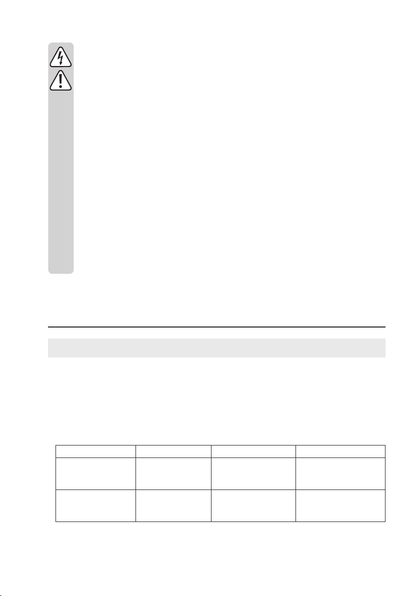
3. Symbol-Erklärung
Das Symbol mit dem Blitz im Dreieck wird verwendet, wenn Gefahr für Ihre Gesundheit besteht,
z.B. durch einen elektrischen Schlag.
Das Symbol mit dem Ausrufezeichen im Dreieck weist auf wichtige Hinweise in dieser Bedienungsanleitung hin, die unbedingt zu beachten sind.
Das Pfeil-Symbol ist zu nden, wenn Ihnen besondere Tipps und Hinweise zur Bedienung gegeben werden sollen.
Nur zur Verwendung in trockenen Innenbereichen
Dieses Gerät ist CE-konform und erfüllt die erforderlichen nationalen und europäischen Richtlinien.
Erdpotential
Schutzleiteranschluss; diese Schraube darf nicht gelöst werden
Der eingebaute Trenntransformator ist nicht kurzschlussfest. Die Schutzeinrichtung ist dem Trafo
nachgeschaltet (elektronische Überlast- und Kurzschlusssicherung).
Achtung heiße Oberäche! Oberäche nicht berühren.
Bedienungsanleitung lesen!
4
Page 5

4. Sicherheitshinweise
Lesen Sie bitte vor Inbetriebnahme die komplette Anleitung durch, sie enthält wichtige Hinweise
zum korrekten Betrieb.
Bei Schäden, die durch Nichtbeachten dieser Bedienungsanleitung verursacht werden, erlischt die
Gewährleistung/Garantie! Für Folgeschäden übernehmen wir keine Haftung!
Bei Sach- oder Personenschäden, die durch unsachgemäße Handhabung oder Nichtbeachten der
Sicherheitshinweise verursacht werden, übernehmen wir keine Haftung! In solchen Fällen erlischt
die Gewährleistung/Garantie.
• Dieses Gerät hat das Werk in sicherheitstechnisch einwandfreien Zustand verlassen.
• Um diesen Zustand zu erhalten und einen gefahrlosen Betrieb sicherzustellen, muss der Anwender die
Sicherheitshinweise und Warnvermerke beachten, die in dieser Gebrauchsanweisung enthalten sind.
• Elektrogeräte und Zubehör sind keine Spielzeuge und gehören nicht in Kinderhände!
• In gewerblichen Einrichtungen sind die Unfallverhütungsvorschriften des Verbandes der gewerblichen
Berufsgenossenschaften für elektrische Anlagen und Betriebsmittel zu beachten.
• In Schulen und Ausbildungseinrichtungen, Hobby- und Selbsthilfewerkstätten ist der Umgang mit Netzgeräten durch geschultes Personal verantwortlich zu überwachen.
• Achten Sie darauf, dass ihre Hände, Schuhe, Kleidung, der Boden und das Netzgerät unbedingt trocken
sind.
• Wartungs-, Einstellungs- oder Reparaturarbeiten dürfen nur von einer Fachkraft/Fachwerkstatt durchgeführt werden, die mit den damit verbundenen Gefahren bzw. einschlägigen Vorschriften vertraut ist.
• Aus Sicherheits- und Zulassungsgründen ist das eigenmächtige Umbauen und/oder Verändern des Produkts nicht gestattet. Öffnen/Zerlegen Sie es nicht! Es sind keinerlei von Ihnen einzustellende oder zu
wartende Teile im Inneren.
• Beim Öffnen von Abdeckungen oder entfernen von Teilen, außer wenn dies von Hand möglich ist, können spannungsführende Teile freigelegt werden.
• Vor einem Öffnen, muss das Gerät von allen Spannungsquellen getrennt werden. Kondensatoren im
Gerät können noch geladen sein, selbst wenn das Gerät von allen Spannungsquellen getrennt wurde.
• Schalten Sie das Labornetzgerät niemals gleich dann ein, wenn es von einem kalten in einen warmen
Raum gebracht wird. Das dabei entstandene Kondenswasser kann unter ungünstigen Umständen Ihr
Gerät zerstören. Lassen Sie das Gerät uneingeschaltet auf Zimmertemperatur kommen.
• Das Netzgerät erwärmt sich bei Betrieb; Achten Sie auf eine ausreichende Belüftung. Lüftungsschlitze
dürfen nicht abgedeckt werden! Fassen Sie den rückseitigen Kühlkörper während des Betriebs nicht an.
Verbrennungsgefahr!
• Aufgrund der Vielzahl von Möbelschutzmitteln könnten die Gerätefüße mit der Oberäche chemisch
reagieren. Stellen Sie das Gerät auf einer unempndlichen, glatten und ebene Oberäche ab.
• Netzgeräte und die angeschlossenen Verbraucher dürfen nicht unbeaufsichtigt betrieben werden.
• Es dürfen nur Sicherungen vom angegebenen Typ und der angegebenen Nennstromstärke eingesetzt
werden. Die Verwendung geickter Sicherungen ist untersagt.
• Die Benutzung metallisch blanker Leitungen ist zu vermeiden.
• Bei Arbeiten mit Netzgeräten ist das Tragen von metallischem oder leitfähigem Schmuck wie Ketten,
Armbändern, Ringen o.ä. verboten.
5
Page 6
• Das Netzgerät ist nicht für die Anwendung an Menschen und Tieren zugelassen.
• Setzen Sie das Gerät keinen mechanischen Beanspruchungen aus. Bereits der Fall aus geringer Höhe
kann das Gerät beschädigen. Vibrationen und direktes Sonnenlicht sind zu vermeiden.
• Stellen Sie keine mit Flüssigkeit gefüllten Gefäße auf dem Gerät ab.
• Gießen Sie nie Flüssigkeiten über oder neben dem Produkt aus. Es besteht höchste Gefahr eines Brandes oder lebensgefährlichen elektrischen Schlages. Sollte dennoch Flüssigkeit ins Geräteinnere gelangt
sein, schalten Sie sofort die Netzsteckdose, an der das Produkt angeschlossen ist, allpolig ab (Sicherung/Sicherungsautomat/FI-Schutzschalter des zugehörigen Stromkreises abschalten). Ziehen Sie erst
danach das Produkt aus der Netzsteckdose und wenden Sie sich an eine Fachkraft. Betreiben Sie das
Produkt nicht mehr.
• Betreiben Sie das Produkt niemals in einem Fahrzeug.
• Wenn anzunehmen ist, dass ein gefahrloser Betrieb nicht mehr möglich ist, so ist das Gerät außer Betrieb zu setzen und gegen unbeabsichtigten Betrieb zu sichern. Es ist anzunehmen, dass ein gefahrloser
Betrieb nicht mehr möglich ist, wenn:
- das Gerät sichtbare Beschädigungen aufweist,
- das Gerät nicht mehr arbeitet und
- nach längerer Lagerung unter ungünstigen Verhältnissen oder
- nach schweren Transportbeanspruchungen.
• Beachten Sie auch die Sicherheitshinweise in den einzelnen Kapiteln bzw. in den Bedienungsanleitungen der angeschlossenen Geräte.
5. VLP 1303 USB // VLP 1405 USB // VLP 1602 USB
5.1. Bestimmungsgemäße Verwendung
• Das Labornetzgerät dient als potentialfreie DC-Spannungsquelle zum Betrieb von Kleinspannungsverbrauchern.
Es stehen drei voneinander unabhängige Ausgänge zur Verfügung. Ein regelbarer Laborausgang, ein regelbarer
USB-Ausgang und ein prozessorgesteuerter USB-Ausgang.
• Bei der Reihenschaltung der Ausgänge mehrerer Netzgeräte können berührungsgefährliche Spannungen
>70 V/DC erzeugt werden. Ab dieser Spannung müssen aus Sicherheitsgründen schutzisolierte Leitungen/Messkabel zum Einsatz kommen. Der Anschluss erfolgt über 4 mm Sicherheits-Buchsen.
• Die Ausgangsdaten der Labornetzgeräte sind wie folgt:
Artikelbezeichnung Ausgang A Ausgang B1-USB Ausgang B2-USB
VLP 1303 USB 0 - 30 V/DC
0,01 - 3 A
VLP 1405 USB 0 - 40 V/DC
0,01 - 5 A
6
4,0 - 6,2 V/DC
0 - 2,5 A
4,0 - 6,2 V/DC
0 - 2,5 A
5 V/DC, max. 2,5 A
9 V/DC, max. 2,0 A
12 V/DC, max. 1,5 A
5 V/DC, max. 2,5 A
9 V/DC, max. 2,0 A
12 V/DC, max. 1,5 A
Page 7

VLP 1602 USB 0 - 60 V/DC
0,01 - 1,5 A
• Spannung und Stromstärke ist bei Ausgang A und Ausgang B1-USB stufenlos regelbar. Die Spannungs- und
Stromanzeige von Ausgang B1-USB erfolgt per Tastendruck über die Anzeige von Ausgang A.
• Der Ausgang B2-USB ist prozessorgesteuert und stellt immer automatisch die besten Ausgangsparameter für das
angeschlossene Endgerät zur Verfügung.
• Die Einstellung für Spannung und Strom erfolgt über Feinregler. Der Spannungsregler für Ausgang A ist als
10-Gang-Potentiometer ausgeführt, um präzise Einstellungen durchzuführen. Die Werte werden im übersichtlichen
Display angezeigt.
• Die Strombegrenzung für den Konstantstrombetrieb kann per Tastendruck voreingestellt werden. Eine Kurzschlussbrücke am Ausgang ist während der Einstellung nicht nötig.
• Für Ausgang A kann zur Sicherheit eine Spannungsbegrenzung (OVP) eingestellt werden. Bei erreichen dieses
Einstellpegels wird der Ausgang automatisch abgeschaltet. Dies verhindert die versehentliche Zerstörung von angeschlossenen Verbrauchern durch eine zu hoch eingestellte Ausgangsspannung.
• Das Gerät ist überlast- und kurzschlussfest und beinhaltet eine Sicherheits-Temperaturabschaltung.
• Das Labornetzgerät ist in Schutzklasse 1 aufgebaut. Es ist nur für den Anschluss an Schutzkontaktsteckdosen mit
Schutzerdung und einer haushaltsüblichen Wechselspannung von 230V/AC zugelassen. Die Erdpotential-Buchse
ist direkt mit Schutzerdung am Netzstecker verbunden.
• Die Netzsteckdose, an der das Produkt angeschlossen wird, muss leicht zugänglich sein.
• Ein Betrieb unter widrigen Umgebungsbedingungen ist nicht zulässig. Widrige Umgebungsbedingungen sind: Nässe oder zu hohe Luftfeuchtigkeit sowie Gewitter bzw. Gewitterbedingungen wie starke elektrostatische Felder usw.
• Der Betrieb in Umgebungen mit hohem Staubanteil, mit brennbaren Gasen, Dämpfen oder Lösungsmitteln ist nicht
gestattet. Es besteht Explosions- und Brandgefahr!
• Eine andere Verwendung als zuvor beschrieben, führt zur Beschädigung dieses Produktes, außerdem ist dies
mit Gefahren wie z.B. Kurzschluss, Brand, elektrischer Schlag etc. verbunden. Das gesamte Produkt darf nicht
geändert bzw. umgebaut werden!
• Die Sicherheitshinweise sind unbedingt zu beachten!
4,0 - 6,2 V/DC
0 - 2,5 A
5 V/DC, max. 2,5 A
9 V/DC, max. 2,0 A
12 V/DC, max. 1,5 A
7
Page 8
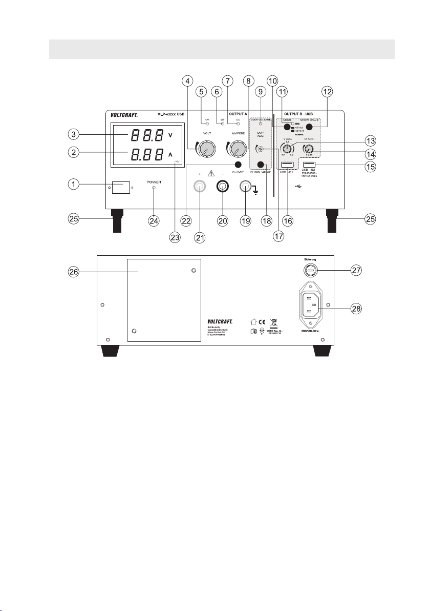
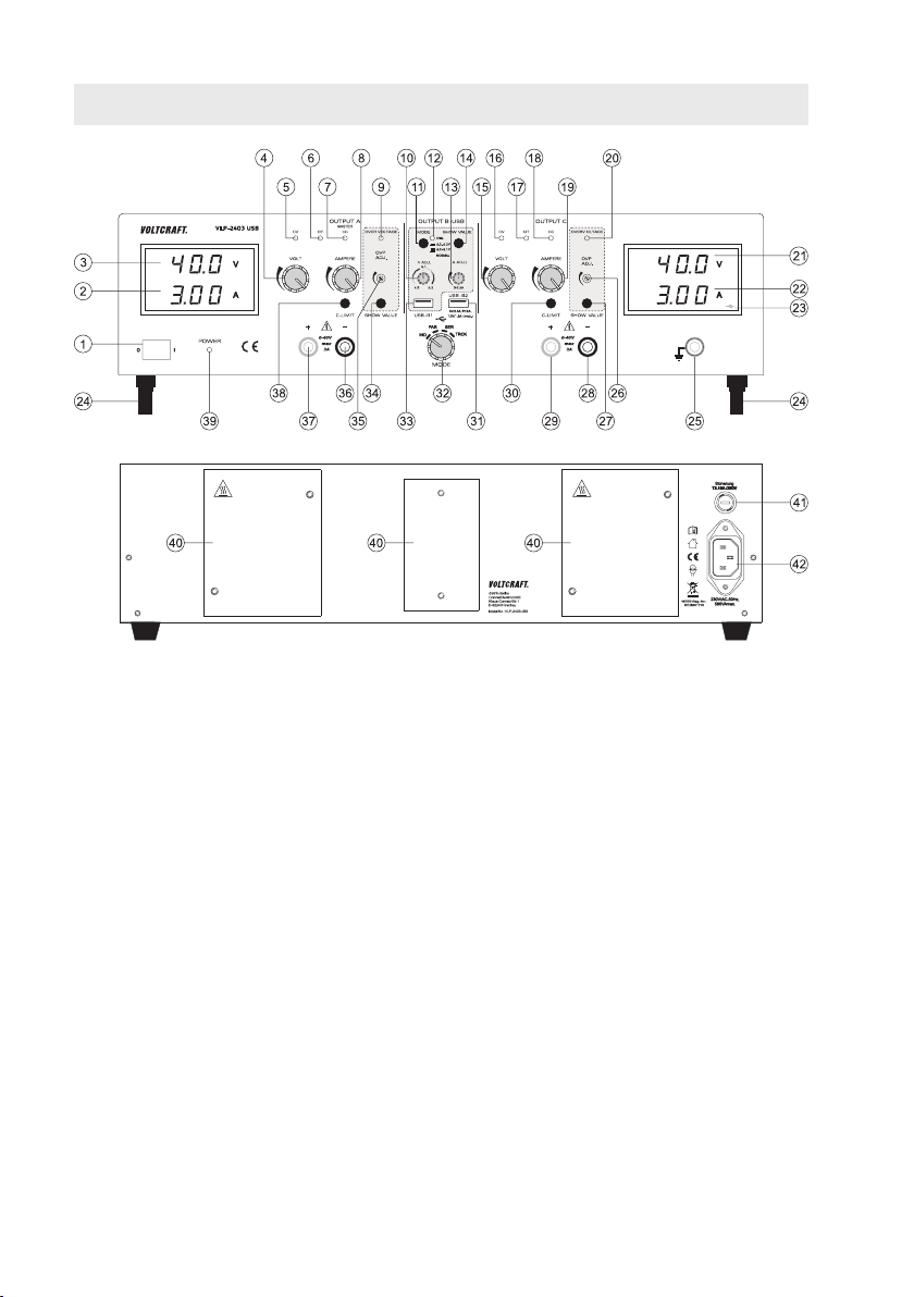
5.2. Bedienelemente
1 Netzschalter zur Inbetriebnahme (I = Ein / 0 = Aus)
2 Anzeige Strom (A)
3 Anzeige Spannung (V)
4 Spannungseinstellregler für Ausgang A (VOLT)
5 Statusanzeige Ausgang A (CV = Konstantspannung)
6 Statusanzeige Ausgang A (OT = Übertemperatur)
7 Statusanzeige Ausgang A (CC = Konstantstrom)
8 Stromeinstellregler für Ausgang A (AMPERE)
9 Statusanzeige bei aktivierter Überspannungsabschaltung (OVER VOLTAGE)
10 Umschalter zur Spannungsbereichswahl von Ausgang B USB-B1
11 Blinkende Statusanzeige bei gedrückter Umschalttaste (10)
8
Page 9
12 Taste zur Anzeige der Spannungs- und Stromeinstellung von Ausgang USB-B1
13 Spannungseinstellregler für Ausgang B USB-B1 (V ADJ.)
14 Stromeinstellregler für Ausgang B USB-B1 (A ADJ.)
15 Prozessorgesteuerter USB-Ausgang B USB-B2
16 Regelbarer USB-Ausgang B USB-B1
17 Einstellregler für den Pegel zur Überspannungsabschaltung (OVP ADJ.)
18 Taste zur Anzeige des eingestellten Pegels zur Überspannungsabschaltung
19 Anschlussbuchse „Erdpotential“
20 Anschlussbuchse Minuspol von Ausgang A
21 Anschlussbuchse Pluspol von Ausgang A
22 Taste „C-LIMIT“ zur Anzeige und Einstellung der Strombegrenzung von Ausgang A
23 USB-Symbol signalisiert die Anzeige von Ausgang B USB-B1
24 Betriebsanzeige bei eingeschaltetem Gerät
25 Gerätefüße an der Vorderseite aufklappbar
26 Rückseitiger Kühlkörper
27 Sicherungshalter für die Netzsicherung
28 Schutzkontakt-Kaltgeräteanschluss für Netzkabel
5.2.1. Symbolerklärung
Folgende Symbole sind an einigen Bedienelementen angebracht.
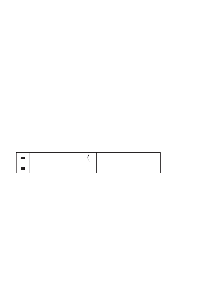
Symbol Taste gedrückt
Symbol Taste nicht gedrückt
Symbol für Regelbereich. Pfeil zeigt Erhöhungsrichtung an.
9
Page 10
5.3. Funktionsbeschreibung
Das Labornetzgerät arbeitet mit zuverlässiger und robuster Lineartechnologie. Dies ermöglicht eine stabile Ausgangsspannung und geringste Störspannungen. Die Gleichspannungsausgänge sind potentialfrei und weisen eine
Schutztrennung gegenüber der Netzspannung auf. Sekundärseitig erfolgt der DC-Anschluss jeweils über zwei farbige
Sicherheits-Buchsen bzw. zwei USB-Buchsen Typ A.
Im übersichtlichen Display erfolgt die Spannungs- und Stromanzeige für den Ausgang A (V = Volt = Einheit der elektrischen Spannung, A = Ampere = Einheit der elektrischen Stromstärke).
Ausgang B1 wird über eine Taste (12) in der Anzeige von Ausgang A angezeigt.
Über Leuchtanzeigen wird der aktuelle Zustand des Netzgerätes signalisiert. Diverse Schutzmechanismen, z.B. Über-
spannungsschutz, Überlastschutz, Strombegrenzung, Überhitzungsschutz etc. sind für den sicheren und zuverlässigen Betrieb eingebaut.
Die Kühlung des Netzgerätes erfolgt über den rückseitigen Kühlkörper. Dies ermöglicht einen lautlosen Betrieb. Auf
eine ausreichende Luftzirkulation ist deshalb zu achten.
Das Netzgerät kann die Ausgangsspannung und den Ausgangsstrom von Ausgang A und USB-B1 stufenlos einstellen.
5.4. Inbetriebnahme
Das Labornetzgerät ist kein Ladegerät. Verwenden Sie zum Laden von Akkus geeignete Ladegeräte
mit entsprechender Ladeabschaltung.
Bei längerem Betrieb mit Nennlast wird die Gehäuseoberäche warm. Achtung! Mögliche
Verbrennungsgefahr ! Achten Sie daher unbedingt auf eine ausreichende Belüftung des Netzgerätes
und betreiben Sie es niemals teilweise oder ganz abgedeckt, um eventuelle Schäden zu vermeiden.
Achten Sie beim Anschluss eines Verbrauchers unbedingt darauf, dass dieser im nicht
eingeschalteten Zustand angeschlossen wird. Ein eingeschalteter Verbraucher kann beim Anschluss
an die Ausgangsbuchsen des Netzgerätes zu einer Funkenbildung führen, welche wiederum die
Buchsen bzw. die angeschlossenen Leitungen und/oder deren Klemmen beschädigen können.
Wenn Sie Ihr Netzgerät nicht benötigen, trennen Sie es vom Netz.
5.4.1. Aufstellen des Gerätes
• Stellen Sie das Labornetzgerät auf eine stabile, ebene und unempndliche Oberäche ab. Achten Sie darauf, dass
die Lüftungsschlitze im Gehäuse nicht verdeckt werden.
Die vorderen Gerätefüße können zur leichteren Ablesung der Anzeigen aufgeklappt werden. Dies ermög-
licht eine Schräglage des Labornetzgerätes.
5.4.2. Anschluss des Netzkabels
• Verbinden Sie das beiliegende Schutzkontakt-Netzkabel mit dem Kaltgeräte-Einbaustecker (28) am Netzgerät.
Achten Sie auf festen Sitz.
• Verbinden Sie das Netzkabel mit einer Schutzkontakt-Steckdose mit Schutzerdung.
• Die Netzsteckdose muss leicht zugänglich sein oder es muss eine allpolige Schutzabschaltung vorhanden sein.
10
Page 11

5.4.3. Ausgangsspannung von Ausgang A einstellen
• Entfernen Sie angeschlossene Verbraucher von Ausgang A (20 und 21).
• Schalten Sie das Netzgerät über den Betriebsschalter (1) ein. Die Betriebsanzeige (24) leuchtet und im Display
erscheint die Spannungs- und Stromanzeige.
• Stellen Sie den Stromeinstellregler „AMPERE“ (8) in Mittelstellung.
• Über den Drehregler „VOLT“ (4) kann die Ausgangsspannung für Ausgang A eingestellt werden.
Im normalen Betrieb arbeitet das Gerät im Konstantspannungsmodus. Das heißt, das Netzgerät gibt
eine konstante voreingestellte Ausgangsspannung ab. Dieser Betrieb wird mit der grünen Statusanzeige
„CV“ (5) signalisiert.
5.4.4. Strombegrenzung von Ausgang A einstellen
Die Begrenzung des Ausgangsstromes ist ein Schutzmechanismus, um den Verbraucher oder die Anschlussleitungen
zu schützen. Die Strombegrenzung kann ohne Kurzschluss am Ausgang voreingestellt werden. Das Netzgerät liefert
maximal den voreingestellten Strom.
• Entfernen Sie angeschlossene Verbraucher von Ausgang A (20 und 21).
• Schalten Sie das Netzgerät über den Betriebsschalter (1) ein. Die Betriebsanzeige (24) leuchtet und im Display
erscheint die Spannungs- und Stromanzeige.
• Drehen Sie den Stromregler „AMPERE“ (8) ganz nach links.
• Drücken Sie die Taste „C-LIMIT“ (22) und halten Sie diese Taste während des Einstellvorganges gedrückt. Der
Ausgang wird automatisch abgeschaltet, solange die Taste „C-LIMIT“ gedrückt wird. Die Spannungsanzeige geht
deshalb auf 0 zurück.
• Über den Drehregler „AMPERE“ (8) kann die max. Stromstärke (Strombegrenzung) eingestellt werden. Lassen
Sie nach erfolgter Einstellung die Taste „C-LIMIT“ los. Das Display zeigt wieder die tatsächliche Stromstärke (bei
unbelastetem Ausgang 0,00 A). Die Statusanzeige „CV“ (5) leuchtet.
• Schließen Sie den Verbraucher an Ausgang A (20 und 21) an und schalten Sie ihn ein. Achten Sie auf die Polarität.
Die LED-Anzeige „CC“ (7) leuchtet, sobald der eingestellte Strompegel überschritten wird und die Strombegrenzung
aktiv ist. Der Konstantstrommodus ist aktiv.
Wird die voreingestellte Stromstärke im Normalbetrieb erreicht, schaltet das Netzgerät in den Strombe-
grenzungsmodus und reduziert dabei den Spannungswert. Dieser Betrieb wird mit der roten Statusanzeige
„CC“ (7) signalisiert.
5.4.5. Überspannungsschutz (OVP) einstellen und Gerät rücksetzen
Der Ausgang A verfügt über einen einstellbaren Überspannungsschutz. Dieser Schutzmechanismus verhindert die
versehentliche Zerstörung von angeschlossenen Verbrauchern durch eine zu hoch eingestellte Ausgangsspannung.
Bei erreichen des voreingestellten Schutzpegels wird der Ausgang A sofort abgeschaltet. Die Ausgänge B1 und B2
sind von der Abschaltung nicht betroffen.
Zum Einstellen des Schutzpegels gehen Sie wie folgt vor
• Drücken Sie bei eingeschaltetem Labornetzgerät die Taste „SHOW VALUE“ (18) und halten Sie diese während der
Einstellprozedur gedrückt.
• Im Display (3) wird der aktuelle Spannungspegel dargestellt.
11
Page 12
• Stellen Sie mit einem passenden Schlitzschraubendreher den gewünschten max. Spannungspegel am Einstellregler „OVP ADJ.“ (17) ein. Wünschen Sie keine Schutzabschaltung, so drehen Sie den Einstellregler auf den
rechten Endanschlag.
• Lassen Sie die Taste „SHOW VALUE“ (18) los. Der Überspannungsschutz ist aktiviert.
Ausgang OUTPUT A zurücksetzen
Sobald über den Einstellregler „VOLT“ (4) der eingestellte Schutzpegel überschritten wird, schaltet der Ausgang
„OUTPUT A“ sofort ab. Die Spannungsanzeige (3) geht auf ca. 0 V zurück und die Statusanzeige „OVER VOLTAGE“
(9) leuchtet rot.
• Entfernen Sie den Verbraucher vom Labornetzgerät.
• Drehen Sie den Einstellregler „VOLT“ einige Umdrehungen entgegen den Uhrzeigersinn.
• Schalten Sie das Labornetzgerät über den Betriebsschalter (1) aus und wieder ein. Dadurch wird die Schutzabschaltung zurückgesetzt.
• Kontrollieren Sie erneut die korrekte Ausgangsspannung und ändern ggf. den Überspannungsschutz.
5.4.6. Ausgangsspannung und Strom von Ausgang B USB-B1 einstellen
Der Ausgang B USB-B1 ist unabhängig vom Ausgang A einsetzbar. Er ermöglicht zu Entwicklungszwecken
die USB-typische Spannung von 5 V/DC variabel von wahlweise 4,0 – 5,1 V/DC oder von 4,0 – 6,2 V/DC
einzustellen. Die Strombegrenzung kann ebenfalls voreingestellt werden.
Um den Einstellbereich festzulegen, kann über den Druckschalter „MODE“ (10) der Einstellbereich festgelegt werden.
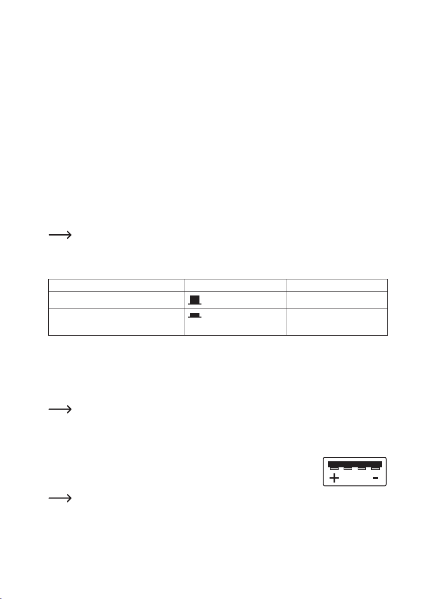
Schaltersymbol Spannungsbereich
Nicht gedrückter Schalterzustand
4,0 - 5,1 V/DC
Gedrückter Schalterzustand.
Anzeige „ENG.“ (11) blinkt.
• Entfernen Sie angeschlossene Verbraucher von Ausgang USB-B1 (16).
• Schalten Sie das Netzgerät über den Betriebsschalter (1) ein. Die Betriebsanzeige (24) leuchtet und im Display
erscheint die Spannungs- und Stromanzeige.
• Drücken Sie die Taste „SHOW VALUE“ (12) und halten diese für die Dauer der Spannungseinstellung gedrückt. Im
Display von Ausgang A wird die Spannung und der Strom von Ausgang B USB-B1 dargestellt.
Das USB-Symbol (23) leuchtet und signalisiert die Anzeige des USB-Ausgangs.
• Über den Drehregler „V ADJ.“ (13) kann die Ausgangsspannung für Ausgang B USB-B1 eingestellt werden.
• Über den Drehregler „A ADJ.“ (14) kann die Strombegrenzung für Ausgang B USB-B1 eingestellt werden.
• Nach erfolgter Einstellung lassen Sie die Taste „SHOW VALUE“ (12) wieder los.
• Schließen Sie den Verbraucher an Ausgang B USB-B1 (16) an und schalten Sie ihn ein.
Achten Sie auf die Polarität. Die USB-Buchse ist standardmäßig beschaltet. Die Skizze
zeigt die Kontaktierung.
Die entsprechenden Spannungs- und Stromwerte können jederzeit durch Drücken der Taste „SHOW
VALUE“ (12) kontrolliert werden.
4,0 - 6,2 V/DC
12
Page 13
5.4.7. Ausgang B USB-B2
Der Ausgang B USB-B2 ist prozessorgesteuert und nicht regelbar. Dieser Ausgang erkennt die Parameter des angeschlossenen Endgerätes und stellt automatisch die bestmögliche Einstellung für Spannung und Strom ein.
Eine Anzeige der vorhandenen Parameter ist nicht möglich.
5.5. Anschluss eines Verbrauchers
Achten Sie beim Anschluss eines Verbrauchers darauf, dass dieser uneingeschaltet mit dem
Netzgerät verbunden wird. Die max. Stromaufnahme des anzuschließenden Verbrauchers darf die
Angaben in den technischen Daten nicht überschreiten.
Bei der Reihenschaltung der Ausgänge mehrerer Netzgeräte können berührungsgefährliche
Spannungen (> 70 V/DC
Ab dieser Spannung darf nur schutzisoliertes Zubehör (Anschlussleitungen, Messleitungen etc.)
verwendet werden.
Die Verwendung metallisch blanker Leitungen und Kontakte ist zu vermeiden. Alle diese blanken
Stellen sind durch geeignete, schwer entammbare Isolierstoffe oder andere Maßnahmen
abzudecken und vor direkter Berührung und Kurzschluss zu schützen.
Achten Sie auf einen ausreichenden Leiterquerschnitt für die vorgesehene Stromstärke.
• Entfernen Sie angeschlossene Verbraucher von den Ausgängen A, B1 und B2.
• Schalten Sie das Netzgerät über den Betriebsschalter (1) ein. Die Betriebsanzeige (24) leuchtet und im Display
erscheint die Spannungs- und Stromanzeige.
• Stellen Sie für die Ausgänge A und USB-B1 die Parameter nach
Ihren Vorgaben wie im Kapitel „Inbetriebnahme“ beschrieben
ein.
• Kontrollieren Sie nochmals die korrekt eingestellte Ausgangsspannung.
• Verbinden Sie bei Ausgang A den Pluspol (+) des Verbrauchers
mit der roten Buchse „+“ und den Minuspol (-) mit der blauen
Buchse „-“.
• Verbinden Sie bei Ausgang B den USB-Stecker des Verbrauchers mit der USB-Buchse.
• Der angeschlossene Verbraucher kann jetzt eingeschaltet werden.
) erzeugt werden, welche bei Berührung lebensgefährlich sein können.
13
Page 14
5.6. Technische Daten
VLP 1303 USB VLP 1405 USB VLP 1602 USB
Ausgangsleistung 123 W 233 W 123 W
Ausgangsspannung Ausgang A 0 - 30 V/DC 0 - 40 V/DC 0 - 60 V/DC
Ausgangsstrom Ausgang A 0,01 - 3 A 0,01 - 5 A 0,01 - 1,5 A
Genauigkeit V-Anzeige ≤ ±(1% + 0.2 V)
Genauigkeit A-Anzeige ≤ ±(2% + 0.02 A)
Ausgangsspannung
Ausgang B USB-B1
Ausgangsstrom
Ausgang B USB-B1
Ausgang B USB-B2
Prozessorgesteuert je nach angeschlossenem
Verbraucher
Restwelligkeit bei Nennlast
Ausgang A, USB-B1
Ausgang USB-B2
Spannungs-Regelverhalten bei 100% Laständerung
Spannungs-Regelverhalten bei 10% Netzschwankung
Strom-Regelverhalten bei 100% Laständerung
Strom-Regelverhalten bei 10% Netzschwankung
Regelstabilität 15 mV/h 25 mV/h 25 mV/h
Display
Betriebsspannung 230 V/AC (±10%) 50 Hz
Leistungsaufnahme (max.) 290 VA 490 VA 270 VA
Netzsicherung Träge (5 x 20 mm) T1,6 A/250 V T3,15 A/250 V T1,6 A/250 V
Betriebstemperatur +5 bis +40 °C
Rel. Luftfeuchtigkeit max. 85%, nicht kondensierend
Schutzklasse 1
Netzanschluss Kaltgeräte-Einbaustecker, IEC 320 C14
Gewicht 6,6 kg 9,0 kg 6,6 kg
Abmessungen (B x H x T) mm 260 x 115 x 270 350 x 125 x 260 260 x 115 x 270
12 mm Siebensegment-Anzeige grün, 3stellig
4,0 - 5,1 V/DC
4,0 - 6,2 V/DC
0,01 - 2,5 A
5 V/DC, max. 2,5 A
9 V/DC, max. 2,0 A
12 V/DC, max. 1,5 A
≤2 mV
≤20 mV
OUTPUT A ≤25 mV
OUTPUT USB-B1 ≤20 mV
OUTPUT A ≤20 mV
OUTPUT USB-B1 ≤15 mV
OUTPUT A ≤20 mA
OUTPUT USB-B1 ≤15 mA
OUTPUT A ≤15 mA
OUTPUT USB-B1 ≤10 mA
Zweizeilig,
14
Page 15
6. VLP 2403 USB
6.1. Bestimmungsgemäße Verwendung
Das Labornetzgerät dient als potentialfreie DC-Spannungsquelle zum Betrieb von Kleinspannungsverbrauchern. Es
stehen vier voneinander unabhängige Ausgänge zur Verfügung. Zwei regelbare Laborausgänge, ein regelbarer USBAusgang und ein prozessorgesteuerter USB-Ausgang.
Die beiden regelbaren Laborausgänge können über einen Modus-Wahlschalter in vier verschiedenen Betriebsarten
betrieben werden.
Individuell (IND)
Jeder Laborausgang (OUTPUT A und OUTPUT C) ist separat und unabhängig einstellbar und nutzbar. Das Gerät
arbeitet wie zwei getrennte Labornetzgeräte.
Parallel (PAR)
Die beiden Laborausgänge (OUTPUT A und C) werden intern parallel zusammengeschaltet. Durch die Parallelschaltung wird der Ausgangsstrom der beiden Ausgänge addiert. Der max. Ausgangsstrom beträgt in diesem Modus max.
6 A. Die Ausgangsspannung beträgt max. 40 V/DC.
Seriell (SER)
Die beiden Laborausgänge (OUTPUT A und C) werden intern in Reihe (in Serie) zusammengeschaltet. Durch die
Serienschaltung wird die Ausgangsspannung der beiden Ausgänge addiert. Die max. Ausgangsspannung beträgt in
diesem Modus max. 80 V/DC. Der Ausgangsstrom beträgt max. 3 A.
Tracking (TRCK)
Im Tracking-Modus wird die Ausgangsspannung der beiden Laborausgänge (Output A und C) über den VOLT-MasterRegler von Ausgang OUTPUT A gesteuert. Die Ausgangsspannung der beiden Ausgänge ist in diesem Modus immer
gleich. Die Strombegrenzung wird am jeweiligen Ausgang eingestellt.
Bei der Serienschaltung der Ausgänge sowie mehrerer Netzgeräte können berührungsgefährliche Span-
nungen >70 V/DC erzeugt werden. Ab dieser Spannung müssen aus Sicherheitsgründen schutzisolierte
Leitungen/Messkabel zum Einsatz kommen. Der Anschluss erfolgt über 4 mm Sicherheits-Buchsen.
Die Ausgangsdaten des Labornetzgerätes sind wie folgt:
Ausgang A Ausgang C Ausgang B1-USB Ausgang B2-USB
0 - 40 V/DC 0 - 40 V/DC 4,0 - 5,1 V/DC 5 V/DC, max. 2,5 A
0,01 - 3 A 0,01 - 3 A 4,0 - 6,2 V/DC 9 V/DC, max. 2,0 A
0 - 2,5 A 12 V/DC, max. 1,5 A
• Spannung und Stromstärke ist bei Ausgang A, C und Ausgang B1-USB stufenlos regelbar. Die Spannungs- und
Stromanzeige von Ausgang B1-USB erfolgt per Tastendruck über die Anzeige von Ausgang C.
• Der Ausgang B2-USB ist prozessorgesteuert und stellt immer automatisch die besten Ausgangsparameter für das
angeschlossene Endgerät zur Verfügung.
• Die Einstellung für Spannung und Strom erfolgt über Feinregler. Der Spannungsregler für Ausgang A und C ist als
Mehrfach-Potentiometer ausgeführt, um präzise Einstellungen durchzuführen. Die Werte werden in zwei übersichtlichen Displays angezeigt.
15
Page 16

• Die Strombegrenzung für den Konstantstrombetrieb bei Ausgang A und C kann per Tastendruck voreingestellt
werden. Eine Kurzschlussbrücke am Ausgang ist während der Einstellung nicht nötig.
• Für die Ausgänge A und C kann zur Sicherheit eine Spannungsbegrenzung (OVP) eingestellt werden. Dies kann
für die beiden Ausgänge unabhängig voneinander erfolgen. Bei erreichen dieses Einstellpegels wird der jeweilige
Ausgang automatisch abgeschaltet. Dies verhindert die versehentliche Zerstörung von angeschlossenen Verbrauchern durch eine zu hoch eingestellte Ausgangsspannung.
• Das Gerät ist überlast- und kurzschlussfest und beinhaltet eine Sicherheits-Temperaturabschaltung.
• Das Labornetzgerät ist in Schutzklasse 1 aufgebaut. Es ist nur für den Anschluss an Schutzkontaktsteckdosen mit
Schutzerdung und einer haushaltsüblichen Wechselspannung von 230V/AC zugelassen. Die Erdpotential-Buchse
ist direkt mit Schutzerdung am Netzstecker verbunden.
• Die Netzsteckdose, an der das Produkt angeschlossen wird, muss leicht zugänglich sein.
• Ein Betrieb unter widrigen Umgebungsbedingungen ist nicht zulässig. Widrige Umgebungsbedingungen sind: Nässe oder zu hohe Luftfeuchtigkeit sowie Gewitter bzw. Gewitterbedingungen wie starke elektrostatische Felder usw.
• Der Betrieb in Umgebungen mit hohem Staubanteil, mit brennbaren Gasen, Dämpfen oder Lösungsmitteln ist nicht
gestattet. Es besteht Explosions- und Brandgefahr!
• Eine andere Verwendung als zuvor beschrieben, führt zur Beschädigung dieses Produktes, außerdem ist dies
mit Gefahren wie z.B. Kurzschluss, Brand, elektrischer Schlag etc. verbunden. Das gesamte Produkt darf nicht
geändert bzw. umgebaut werden!
• Die Sicherheitshinweise sind unbedingt zu beachten!
6.2. Funktionsbeschreibung
Das Labornetzgerät arbeitet mit zuverlässiger und robuster Lineartechnologie. Dies ermöglicht eine stabile Ausgangsspannung und geringste Störspannungen. Die Gleichspannungsausgänge sind potentialfrei und weisen eine
Schutztrennung gegenüber der Netzspannung auf. Sekundärseitig erfolgt der DC-Anschluss jeweils über zwei farbige
Sicherheits-Buchsen bzw. zwei USB-Buchsen Typ A.
Das Netzgerät kann die Ausgangsspannung und den Ausgangsstrom von Ausgang A, Ausgang C und USB-B1 stufenlos einstellen.
In 2 übersichtlichen Displays erfolgt die Spannungs- und Stromanzeige für die Ausgänge A und C (V = Volt = Einheit
der elektrischen Spannung, A = Ampere = Einheit der elektrischen Stromstärke).
Ausgang USB B1 wird über eine Taste in der Anzeige von Ausgang C angezeigt.
Über Leuchtanzeigen wird der aktuelle Zustand des Netzgerätes signalisiert. Diverse Schutzmechanismen, z.B. Über-
spannungsschutz, Überlastschutz, Strombegrenzung, Überhitzungsschutz etc. sind für den sicheren und zuverlässigen Betrieb eingebaut.
Die Kühlung des Netzgerätes erfolgt über die rückseitigen Kühlkörper. Dies ermöglicht einen lautlosen Betrieb. Auf
eine ausreichende Luftzirkulation ist deshalb zu achten.
16
Page 17
6.3. Bedienelemente
1 Netzschalter zur Inbetriebnahme (I = Ein / 0 = Aus)
2 Anzeige Strom (A) für Ausgang OUTPUT A
3 Anzeige Spannung (V) für Ausgang OUTPUT A
4 Spannungseinstellregler (VOLT) für Ausgang A
5 Statusanzeige Ausgang A (CV = Konstantspannung)
6 Statusanzeige Ausgang A (OT = Übertemperatur)
7 Statusanzeige Ausgang A (CC = Konstantstrom)
8 Stromeinstellregler (AMPERE) für Ausgang A
9 Statusanzeige bei aktivierter Überspannungsabschaltung (OVER VOLTAGE) für Ausgang A
10 Spannungseinstellregler (V ADJ.) für Ausgang B USB-B1
11 Umschalter zur Spannungsbereichswahl von Ausgang B USB-B1
12 Blinkende Statusanzeige bei gedrückter Umschalttaste (11)
13 Stromeinstellregler (A ADJ.) für Ausgang B USB-B1
14 Taste zur Anzeige der Spannungs- und Stromeinstellung von Ausgang USB-B1
15 Spannungseinstellregler (VOLT) für Ausgang C
16 Statusanzeige Ausgang C (CV = Konstantspannung)
17
Page 18

17 Statusanzeige Ausgang C (OT = Übertemperatur)
18 Statusanzeige Ausgang C (CC = Konstantstrom)
19 Stromeinstellregler (AMPERE) für Ausgang C
20 Statusanzeige bei aktivierter Überspannungsabschaltung (OVER VOLTAGE) für Ausgang C
21 Anzeige Spannung (V) für Ausgang C
22 Anzeige Strom (A) für Ausgang C
23 USB-Symbol signalisiert die Anzeige von Ausgang B USB-B1
24 Gerätefüße an der Vorderseite aufklappbar
25 Anschlussbuchse „Erdpotential“
26 Einstellregler für den Pegel zur Überspannungsabschaltung (OVP ADJ.) für Ausgang C
27 Taste zur Anzeige des eingestellten Pegels zur Überspannungsabschaltung für Ausgang C
28 Anschlussbuchse Minuspol von Ausgang C
29 Anschlussbuchse Pluspol von Ausgang C
30 Taste „C-LIMIT“ zur Anzeige und Einstellung der Strombegrenzung von Ausgang C
31 Prozessorgesteuerter USB-Ausgang B USB-B2
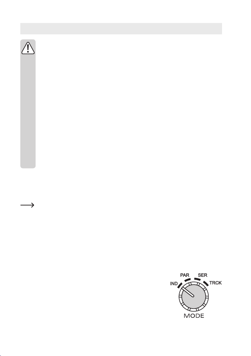
32 Umschalter „MODE“ für die Wahl der Betriebsart
33 Regelbarer USB-Ausgang B USB-B1
34 Taste zur Anzeige des eingestellten Pegels zur Überspannungsabschaltung für Ausgang A
35 Einstellregler für den Pegel zur Überspannungsabschaltung (OVP ADJ.) für Ausgang A
36 Anschlussbuchse Minuspol von Ausgang A
37 Anschlussbuchse Pluspol von Ausgang A
38 Taste „C-LIMIT“ zur Anzeige und Einstellung der Strombegrenzung von Ausgang A
39 Betriebsanzeige bei eingeschaltetem Gerät
40 Rückseitige Kühlkörper
41 Sicherungshalter für die Netzsicherung
42 Schutzkontakt-Kaltgeräteanschluss für Netzkabel
6.3.1. Symbolerklärung
Folgende Symbole sind an einigen Bedienelementen angebracht.
Symbol Taste gedrückt
Symbol Taste nicht gedrückt
Symbol für Regelbereich. Pfeil zeigt Erhöhungsrichtung an.
18
Page 19
6.4. Inbetriebnahme
Das Labornetzgerät ist kein Ladegerät. Verwenden Sie zum Laden von Akkus geeignete Ladegeräte
mit entsprechender Ladeabschaltung.
Bei längerem Betrieb mit Nennlast wird die Gehäuseoberäche warm. Achtung! Mögliche Verbrennungsgefahr ! Achten Sie daher unbedingt auf eine ausreichende Belüftung des Netzgerätes und
betreiben Sie es niemals teilweise oder ganz abgedeckt, um eventuelle Schäden zu vermeiden.
Achten Sie beim Anschluss eines Verbrauchers unbedingt darauf, dass dieser im nicht eingeschalteten Zustand angeschlossen wird. Ein eingeschalteter Verbraucher kann beim Anschluss an die
Ausgangsbuchsen des Netzgerätes zu einer Funkenbildung führen, welche wiederum die Buchsen
bzw. die angeschlossenen Leitungen und/oder deren Klemmen beschädigen können.
Wenn Sie Ihr Netzgerät nicht benötigen, trennen Sie es vom Netz.
Die max. Stromaufnahme des anzuschließenden Verbrauchers darf die Angaben in den technischen Daten nicht überschreiten.
Bei der Reihenschaltung der Ausgänge bzw. mehrerer Netzgeräte können berührungsgefährliche
Spannungen (> 70 V/DC) erzeugt werden, welche bei Berührung lebensgefährlich sein können.
Ab dieser Spannung darf nur schutzisoliertes Zubehör (Anschlussleitungen, Messleitungen etc.)
verwendet werden.
Die Verwendung metallisch blanker Leitungen und Kontakte ist zu vermeiden. Alle diese blanken
Stellen sind durch geeignete, schwer entammbare Isolierstoffe oder andere Maßnahmen abzudecken und vor direkter Berührung und Kurzschluss zu schützen.
Achten Sie auf einen ausreichenden Leiterquerschnitt für die vorgesehene Stromstärke.
6.4.1. Aufstellen des Gerätes
• Stellen Sie das Labornetzgerät auf eine stabile, ebene und unempndliche Oberäche ab. Achten Sie darauf, dass
die Lüftungsschlitze im Gehäuse nicht verdeckt werden.
Die vorderen Gerätefüße können zur leichteren Ablesung der Anzeigen aufgeklappt werden. Dies ermög-
licht eine Schräglage des Labornetzgerätes.
6.4.2. Anschluss des Netzkabels
• Verbinden Sie das beiliegende Schutzkontakt-Netzkabel mit dem Kaltgeräte-Einbaustecker (42) am Netzgerät.
Achten Sie auf festen Sitz.
• Verbinden Sie das Netzkabel mit einer Schutzkontakt-Steckdose mit Schutzerdung.
• Die Netzsteckdose muss leicht zugänglich sein oder es muss eine allpolige Schutzabschaltung vorhanden sein
(z.B. Notaus-Schalter).
6.4.3. Einschalten und Betriebsart einstellen
Am Labornetzgerät können für die beiden Haupt-Laborausgänge OUTPUT A und
OUTPUT C vier unterschiedliche Betriebsarten eingestellt werden.
Schalten Sie das Netzgerät über den Betriebsschalter (1) ein. Die Betriebsanzeige
(39) leuchtet und in den beiden Displays erscheinen die Spannungs- und Stromanzeigen.
19
Page 20
Um die Betriebsart zu Wählen, drehen Sie den Drehschalter „MODE“ (32) in die entsprechende Position.
Achten Sie vor der Umstellung der Funktion, dass kein Verbraucher an den beiden Ausgängen A und C
angeschlossen sind. Diese könnten im ungünstigen Fall durch Überspannung beschädigt werden.
6.4.4. Individual-Betrieb (IND)
Jeder Laborausgang (OUTPUT A und OUTPUT C) ist separat und unabhängig einstellbar und nutzbar. Das Gerät
arbeitet wie zwei getrennte Labornetzgeräte. Dies ist der Standard-Betriebsmodus.
Ausgangsspannung von Ausgang A bzw. C einstellen
• Entfernen Sie angeschlossene Verbraucher von Ausgang A (36 und 37) und Ausgang C (28 und 29).
• Stellen Sie den Stromeinstellregler für den jeweiligen Ausgang „AMPERE“ (8 bzw. 19) in Mittelstellung.
• Über den Drehregler „VOLT“ (4 bzw. 15) kann die Ausgangsspannung eingestellt werden.
• Der Spannungswert „V“ wird im Display (3 bzw. 21) angezeigt
Im normalen Betrieb arbeitet das Gerät im Konstantspannungsmodus. Das heißt, das Netzgerät gibt eine
konstante voreingestellte Ausgangsspannung ab. Dieser Betrieb wird mit der grünen Statusanzeige „CV“
(5 bzw. 16) signalisiert.
Strombegrenzung von Ausgang A bzw. C einstellen
Die Begrenzung des Ausgangsstromes ist ein Schutzmechanismus, um den Verbraucher oder die Anschlussleitungen
zu schützen. Die Strombegrenzung kann ohne Kurzschluss am Ausgang voreingestellt werden. Das Netzgerät liefert
maximal den voreingestellten Strom.
• Entfernen Sie angeschlossene Verbraucher von Ausgang A (36 und 37) und Ausgang C (28 und 29). Stellen Sie vor
der Einstellung der Strombegrenzung immer erst die korrekte Ausgangsspannung ein.
• Drehen Sie den Stromregler „AMPERE“ (8 bzw. 19) ganz nach links (Nullposition).
• Drücken Sie die Taste „C-LIMIT“ (30 bzw. 38) und halten Sie diese Taste während des Einstellvorganges gedrückt.
Der entsprechende Ausgang wird automatisch abgeschaltet, solange die Taste „C-LIMIT“ gedrückt wird. Die Spannungsanzeige geht deshalb auf ca. 0 zurück.
• Über den Drehregler „AMPERE“ (8 bzw. 19) kann die max. Stromstärke (Strombegrenzung) eingestellt werden.
Lassen Sie nach erfolgter Einstellung die Taste „C-LIMIT“ los. Das Display zeigt wieder die tatsächliche Stromstärke (bei unbelastetem Ausgang 0,00 A). Die Statusanzeige „CV“ (5 bzw. 16) leuchtet.
20
Page 21
• Schließen Sie den Verbraucher an Ausgang A (36 und 37) oder Ausgang C (28 und 29) an und schalten Sie ihn
ein. Achten Sie auf die Polarität.
Die LED-Anzeige „CC“ (7 bzw. 18) leuchtet, sobald der eingestellte Strompegel überschritten wird und die Strombegrenzung aktiv ist. Der Konstantstrommodus ist aktiv.
Wird die voreingestellte Stromstärke im Normalbetrieb erreicht, schaltet das Netzgerät in den Strombe-
grenzungsmodus und reduziert dabei den Spannungswert. Dieser Betrieb wird mit der roten Statusanzeige
„CC“ (7 bzw. 18) signalisiert.
Überspannungsschutz (OVP) einstellen und Gerät rücksetzen
Die Ausgänge A und C verfügen über einen einstellbaren Überspannungsschutz. Dieser Schutzmechanismus verhindert die versehentliche Zerstörung von angeschlossenen Verbrauchern durch eine zu hoch eingestellte Ausgangsspannung. Bei erreichen des voreingestellten Schutzpegels wird der entsprechende Ausgang (A oder C) sofort abgeschaltet. Die USB-Ausgänge sind von der Abschaltung nicht betroffen.
Zum Einstellen des Schutzpegels gehen Sie wie folgt vor:
• Drücken Sie bei eingeschaltetem Labornetzgerät die Taste „SHOW VALUE“ (34 bzw. 27) und halten Sie diese
während der Einstellprozedur gedrückt.
• Im Display (3 bzw. 21) wird der aktuelle Spannungspegel dargestellt.
• Stellen Sie mit einem passenden Schlitzschraubendreher den gewünschten max. Spannungspegel am Einstellregler „OVP ADJ.“ (35 bzw. 26) ein. Wünschen Sie keine Schutzabschaltung, so drehen Sie den Einstellregler auf
den rechten Endanschlag.
• Lassen Sie die Taste „SHOW VALUE“ (34 bzw. 27) los. Der Überspannungsschutz ist aktiviert.
Ausgang A bzw. C zurücksetzen:
• Sobald über den Einstellregler „VOLT“ (4 bzw. 15) der eingestellte Schutzpegel überschritten wird, schaltet der
entsprechende Ausgang A oder C sofort ab. Die Spannungsanzeige (3 bzw. 21) geht auf ca. 0 V zurück und die
Statusanzeige „OVER VOLTAGE“ (9 bzw. 20) leuchtet rot.
• Entfernen Sie den Verbraucher vom Labornetzgerät.
• Drehen Sie den Einstellregler „VOLT“ einige Umdrehungen entgegen den Uhrzeigersinn.
• Schalten Sie das Labornetzgerät über den Betriebsschalter (1) aus. Warten Sie ca. 3 Sekunden und schalten das
Gerät wieder ein. Dadurch wird die Schutzabschaltung zurückgesetzt.
Kontrollieren Sie erneut die korrekte Ausgangsspannung und ändern ggf. den Überspannungsschutz.
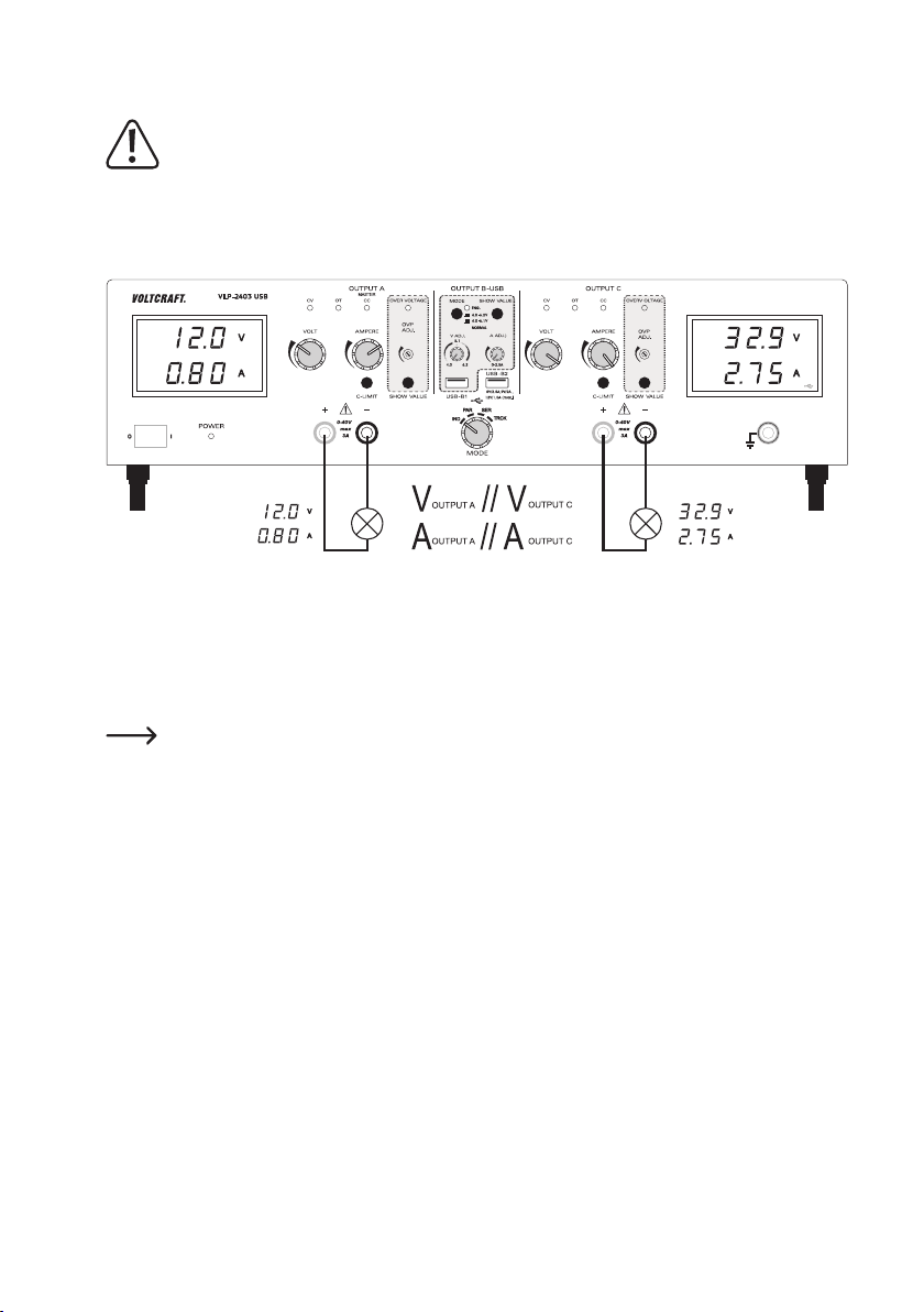
6.4.5. Parallel-Betrieb (PAR)
Die beiden Laborausgänge (OUTPUT A und C) werden intern parallel zusammengeschaltet. Durch die Parallelschaltung wird der Ausgangsstrom der beiden Ausgänge addiert. Der max. Ausgangsstrom beträgt in diesem Modus max.
6 A. Die Ausgangsspannung beträgt max. 40 V/DC.
Durch die interne Beschaltung ist es möglich den max. Ausgangsstrom von 6 A direkt am Ausgang A abzugreifen.
Externe Kabelbrücken sind nicht erforderlich.
Entfernen Sie angeschlossene Verbraucher von Ausgang A (36 und 37) und Ausgang C (28 und 29) bevor
Sie die Betriebsart wechseln.
21
Page 22
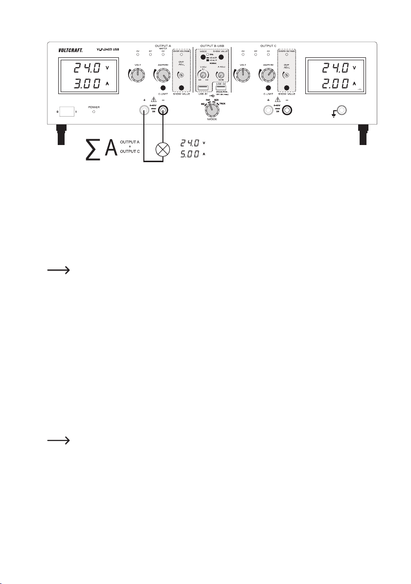
Ausgangsspannung einstellen
• Wählen Sie am Drehschalter„MODE (32) die Betriebsart „PAR“.
• Stellen Sie die beiden Stromeinstellregler „AMPERE“ (8 bzw. 19) in Mittelstellung.
• Über den Drehregler „VOLT“ (4 bzw. 15) kann die Ausgangsspannung eingestellt werden. Drehen Sie im unteren
Spannungsbereich bis ca. 12 V abwechselnd die beiden Drehregler „VOLT“ (4 bzw. 15). Ab 12 V ist es ausreichend
die Spannung über den Drehregler von Ausgang A einzustellen.
• Der Spannungswert „V“ wird im Display (3 bzw. 21) angezeigt. Die beiden Spannungsanzeigen (3 und 21) zeigen
die selbe Spannung am Ausgang und dürfen nicht addiert werden.
Im normalen Betrieb arbeitet das Gerät im Konstantspannungsmodus. Das heißt, das Netzgerät gibt eine
konstante voreingestellte Ausgangsspannung ab. Dieser Betrieb wird mit der grünen Statusanzeige „CV“
(5 bzw. 16) signalisiert.
Strombegrenzung von Ausgang A bzw. C einstellen
• Entfernen Sie angeschlossene Verbraucher von Ausgang A (36 und 37) und Ausgang C(28 und 29). Stellen Sie vor
der Einstellung der Strombegrenzung immer erst die korrekte Ausgangsspannung ein.
• Drehen Sie den Stromregler „AMPERE“ (8 bzw. 19) ganz nach links (Nullposition).
• Drücken Sie die Taste „C-LIMIT“ (30 bzw. 38) und halten Sie diese Taste während des Einstellvorganges gedrückt.
Der entsprechende Ausgang wird automatisch abgeschaltet, solange die Taste „C-LIMIT“ gedrückt wird. Die Spannungsanzeige geht deshalb auf ca. 0 zurück.
• Über den Drehregler „AMPERE“ (8 bzw. 19) kann die max. Stromstärke (Strombegrenzung) eingestellt werden.
Lassen Sie nach erfolgter Einstellung die Taste „C-LIMIT“ los. Das Display zeigt wieder die tatsächliche Stromstärke (bei unbelastetem Ausgang 0,00 A). Die Statusanzeige „CV“ (5 bzw. 16) leuchtet.
• Schließen Sie den Verbraucher an Ausgang A (36 und 37) an und schalten Sie ihn ein. Achten Sie auf die Polarität.
Die Ausgangsströme der beiden Ausgänge addieren sich und werden am Ausgang A gebündelt.
Die LED-Anzeige „CC“ (7 bzw. 18) leuchtet am jeweiligen Ausgang, sobald der eingestellte Strompegel
überschritten wird und die Strombegrenzung aktiv ist. Der Konstantstrommodus ist aktiv.
22
Page 23
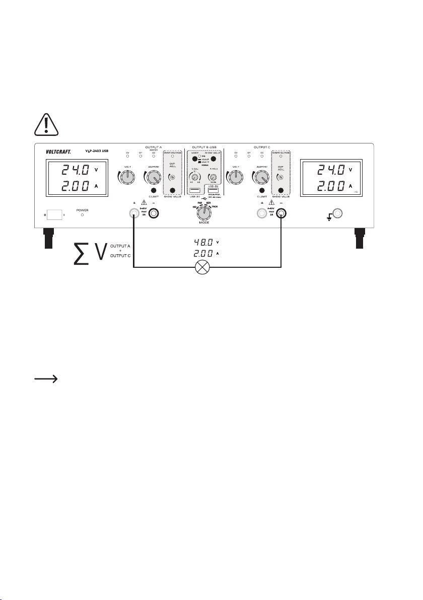
6.4.6. Serien-Betrieb (SER)
Die beiden Laborausgänge (OUTPUT A und C) werden intern in Reihe (in Serie) zusammengeschaltet. Durch die
Serienschaltung wird die Ausgangsspannung der beiden Ausgänge addiert. Die max. Ausgangsspannung beträgt in
diesem Modus max. 80 V/DC. Der Ausgangsstrom beträgt max. 3 A.
Durch die interne Beschaltung ist es möglich die max. Ausgangsspannung von 80 V direkt über zwei Buchsen von
Ausgang A und C abzugreifen. Externe Kabelbrücken sind nicht erforderlich.
Entfernen Sie angeschlossene Verbraucher von Ausgang A (36 und 37) und Ausgang C (28 und 29) bevor
Sie die Betriebsart wechseln.
Ausgangsspannung einstellen
• Wählen Sie am Drehschalter„MODE (32) die Betriebsart „SER“.
• Stellen Sie die beiden Stromeinstellregler „AMPERE“ (8 bzw. 19) in Mittelstellung.
• Über den Drehregler „VOLT“ (4 bzw. 15) kann die Ausgangsspannung eingestellt werden. Beachten Sie, dass die
beiden eingestellten Spannungen am Ausgang addiert werden.
• Die Spannungswerte „V“ werden im Display (3 und 21) angezeigt und müssen addiert werden. An den beiden
Ausgangsbuchsen (37 und 28) wird die Summe der Spannungseinstellung ausgegeben.
Im normalen Betrieb arbeitet das Gerät im Konstantspannungsmodus. Das heißt, das Netzgerät gibt eine
konstante voreingestellte Ausgangsspannung ab. Dieser Betrieb wird mit der grünen Statusanzeige „CV“
(5 bzw. 16) signalisiert.
Strombegrenzung einstellen
• Entfernen Sie angeschlossene Verbraucher von Ausgang A (36 und 37) und Ausgang C(28 und 29). Stellen Sie vor
der Einstellung der Strombegrenzung immer erst die korrekte Ausgangsspannung ein.
• Drehen Sie den Stromregler „AMPERE“ (8 bzw. 19) ganz nach links (Nullposition).
• Drücken Sie die Taste „C-LIMIT“ (30 bzw. 38) und halten Sie diese Taste während des Einstellvorganges gedrückt.
Der entsprechende Ausgang wird automatisch abgeschaltet, solange die Taste „C-LIMIT“ gedrückt wird. Die Spannungsanzeige geht deshalb auf ca. 0 zurück.
• Über den Drehregler „AMPERE“ (8 bzw. 19) kann die max. Stromstärke (Strombegrenzung) eingestellt werden.
Lassen Sie nach erfolgter Einstellung die Taste „C-LIMIT“ los. Das Display zeigt wieder die tatsächliche Stromstärke (bei unbelastetem Ausgang 0,00 A). Die Statusanzeige „CV“ (5 bzw. 16) leuchtet.
23
Page 24
• Schließen Sie den Verbraucher an den Ausgangsbuchsen „+“ von Ausgang A (37) und „-„ von Ausgang C (28) an
und schalten Sie ihn ein. Achten Sie auf die Polarität. Die Ausgangsspannungen der beiden Ausgänge addieren
sich und werden am Ausgang gebündelt.
Die LED-Anzeige „CC“ (7 bzw. 18) leuchtet am jeweiligen Ausgang, sobald der eingestellte Strompegel
überschritten wird und die Strombegrenzung aktiv ist. Der Konstantstrommodus ist aktiv.
6.4.7. Tracking-Betrieb (TRCK)
Im Tracking-Modus wird die Ausgangsspannung der beiden Laborausgänge (Output A und C) über den VOLT-MasterRegler (4) von Ausgang OUTPUT A gesteuert. Die Ausgangsspannung der beiden Ausgänge ist in diesem Modus
immer gleich. Die Strombegrenzung wird am jeweiligen Ausgang eingestellt.
Ausgangsspannung einstellen
• Entfernen Sie angeschlossene Verbraucher von Ausgang A (36 und 37) und Ausgang C (28 und 29).
• Stellen Sie den Stromeinstellregler für den jeweiligen Ausgang „AMPERE“ (8 bzw. 19) in Mittelstellung.
• Der Spannungsregler von Ausgang C (15) muss in dieser Betriebsart auf Maximum gestellt werden (rechter Endanschlag). Dies ermöglicht die alleinige Steuerung durch Ausgang A.
• Über den Spannungsregler „VOLT“ (4) von Ausgang A kann die Ausgangsspannung für beide Ausgänge eingestellt
werden.
• Der Spannungswert „V“ wird im Display (3 bzw. 21) angezeigt.
Im normalen Betrieb arbeitet das Gerät im Konstantspannungsmodus. Das heißt, das Netzgerät gibt eine
konstante voreingestellte Ausgangsspannung ab. Dieser Betrieb wird mit der grünen Statusanzeige „CV“
(5 bzw. 16) signalisiert.
Strombegrenzung von Ausgang A bzw. C einstellen
• Die Begrenzung des Ausgangsstromes ist ein Schutzmechanismus, um den Verbraucher oder die Anschlussleitungen zu schützen. Die Strombegrenzung kann ohne Kurzschluss am Ausgang voreingestellt werden. Das Netzgerät
liefert maximal den voreingestellten Strom.
• Entfernen Sie angeschlossene Verbraucher von Ausgang A (36 und 37) und Ausgang C(28 und 29). Stellen Sie vor
der Einstellung der Strombegrenzung immer erst die korrekte Ausgangsspannung ein.
• Drehen Sie den Stromregler „AMPERE“ (8 bzw. 19) ganz nach links (Nullposition).
24
Page 25
• Drücken Sie die Taste „C-LIMIT“ (30 bzw. 38) und halten Sie diese Taste während des Einstellvorganges gedrückt.
Der entsprechende Ausgang wird automatisch abgeschaltet, solange die Taste „C-LIMIT“ gedrückt wird. Die Spannungsanzeige geht deshalb auf ca. 0 zurück.
• Über den Drehregler „AMPERE“ (8 bzw. 19) kann die max. Stromstärke (Strombegrenzung) eingestellt werden.
Lassen Sie nach erfolgter Einstellung die Taste „C-LIMIT“ los. Das Display zeigt wieder die tatsächliche Stromstärke (bei unbelastetem Ausgang 0,00 A). Die Statusanzeige „CV“ (5 bzw. 16) leuchtet.
• Schließen Sie den Verbraucher an Ausgang A (36 und 37) oder Ausgang C (28 und 29) an und schalten Sie ihn
ein. Achten Sie auf die Polarität.
• Die LED-Anzeige „CC“ (7 bzw. 18) leuchtet, sobald der eingestellte Strompegel überschritten wird und die Strombegrenzung aktiv ist. Der Konstantstrommodus ist aktiv.
Wird die voreingestellte Stromstärke im Normalbetrieb erreicht, schaltet das Netzgerät in den Strombe-
grenzungsmodus und reduziert dabei den Spannungswert. Dieser Betrieb wird mit der roten Statusanzeige
„CC“ (7 bzw. 18) signalisiert.
6.4.8. USB-Ausgang
Es stehen zwei unabhängige USB-Ausgänge zur Verfügung. Die Einstellungen und Sicherheitsabschaltungen von
Ausgang A und C beeinussen die beiden USB-Ports nicht.
Bei Ausgang USB-B1 (33) kann die Ausgangsspannung und die Strombegrenzung stufenlos eingestellt werden.
Bei Ausgang USB-B2 (31) werden die Ausgangsparameter prozessorgesteuert je nach angeschlossenem Endgerät
automatisch und optimal eingestellt.
Ausgangsspannung und Strom von Ausgang B USB-B1 einstellen
Der Ausgang B USB-B1 ermöglicht zu Entwicklungszwecken die USB-typische Spannung von 5 V/DC variabel von
wahlweise 4,0 – 5,1 V/DC oder von 4,0 – 6,2 V/DC einzustellen. Die Strombegrenzung kann ebenfalls voreingestellt
werden.
Um den Einstellbereich festzulegen, kann über den Druckschalter „MODE“ (11) der Einstellbereich festgelegt werden.
Schaltersymbol Spannungsbereich
Nicht gedrückter Schalterzustand
Gedrückter Schalterzustand.
Anzeige „ENG.“ (12) blinkt.
• Entfernen Sie angeschlossene Verbraucher von Ausgang USB-B1 (33).
• Drücken Sie die Taste „SHOW VALUE“ (14) und halten diese für die Dauer der
Spannungseinstellung gedrückt. Im Display von Ausgang C wird die Spannung
von Ausgang B USB-B1 dargestellt.
• Über den Drehregler „V ADJ.“ (10) kann die Ausgangsspannung für Ausgang B
USB-B1 eingestellt werden.
• Über den Drehregler „A ADJ.“ (13) kann die Strombegrenzung für Ausgang B
USB-B1 angeglichen werden um sicherstellen, dass der Stromwert hoch genug
ist, um die Spannung nicht abzuschalten.
• Nach erfolgter Einstellung lassen Sie die Taste „SHOW VALUE“ (14) wieder los.
4,0 - 5,1 V/DC
4,0 - 6,2 V/DC
25
Page 26
Schließen Sie den Verbraucher an Ausgang B USB-B1 (33) an und schalten Sie ihn ein. Achten Sie auf die Polarität.
Der maximale Stromwert beträgt 2,5 A, eine Strombegrenzung löst bei Überschreitung dieser Ausgänge automatisch
aus. Die USB-Buchse ist standardmäßig beschaltet. Die Skizze zeigt die Kontaktierung.
Die entsprechenden Spannungs- und Stromwerte können jederzeit durch Drücken der Taste „SHOW VA-
LUE“ (14) kontrolliert werden.
Ausgang B USB-B2
Der Ausgang B USB-B2 ist prozessorgesteuert und nicht regelbar. Dieser Ausgang erkennt die Parameter des angeschlossenen Endgerätes und stellt automatisch die bestmögliche Einstellung für Spannung und Strom ein.
Eine Anzeige der vorhandenen Parameter ist nicht möglich. Der Anschluss erfolgt an Ausgang B USB-B2 (31).
6.5. Technische Daten
Ausgang OUTPUT A OUTPUT C USB-B1 USB-B2
Ausgangsleistung 273 W
Ausgangsspannung V/DC 0 - 40 V
Ausgangsstrom 0,01 - 3 A 0,01 - 3 A 0,01 - 2,5 A max. 2,5 A
Restwelligkeit bei Nennlast ≤2 mV ≤2 mV ≤2 mV ≤20 mV
Spannungs-Regelverhalten bei
100% Laständerung
Spannungs-Regelverhalten bei
10% Netzschwankung
Strom-Regelverhalten bei 100%
Laständerung
Strom-Regelverhalten bei 10%
Netzschwankung
Regelstabilität 25 mV/h
Display Zweizeilig, 12 mm Siebensegment-Anzeige grün, 3stellig
Genauigkeit V-Anzeige ≤ ±(1% + 0.2 V)
Genauigkeit A-Anzeige ≤ ±(2% + 0.02 A)
Betriebsspannung 230 V/AC (±10%) 50 Hz
Leistungsaufnahme (max.) 590 VA
Netzsicherung Träge (5 x 20 mm) T3,15A/250V
Betriebstemperatur +5 bis +40 °C
Rel. Luftfeuchtigkeit max. 85%, nicht kondensierend
(-200 mV ~ 41.5 V)
≤25 mV ≤25 mV ≤20 mV Nicht speziziert
≤20 mV ≤20 mV ≤15 mV Nicht speziziert
≤20 mA ≤20 mA ≤15 mA Nicht speziziert
≤15 mA ≤15 mA ≤10 mA Nicht speziziert
0 - 40 V
(-200 mV ~ 41.5 V)
4,0 - 5,1 V
4,0 - 6,2 V
(-0.2V/+ 0.1V)
5 V
9 V
12 V
max. 2,0 A
max. 1,5 A
26
Page 27
Schutzklasse 1
Netzanschluss Kaltgeräte-Einbaustecker, IEC 320 C14
Gewicht 11,0 kg
Abmessungen (B x H x T) 440 x 125 x 270 mm
7. Entsorgung
Elektronische Altgeräte sind Wertstoffe und gehören nicht in den Hausmüll. Entsorgen Sie das Produkt am
Ende seiner Lebensdauer gemäß den geltenden gesetzlichen Bestimmungen.
8. Wartung und Reinigung
Bis auf eine gelegentliche Reinigung oder einen Sicherungswechsel ist das Labornetzgerät wartungsfrei. Zur Reinigung des Gerätes nehmen Sie ein sauberes, fusselfreies, antistatisches und trockenes Reinigungstuch ohne scheuernde, chemische und lösungsmittelhaltige Reinigungsmittel.
8.1. Netzsicherung wechseln
Lässt sich das Labornetzgerät nicht mehr einschalten, so ist vermutlich die rückseitige Netzsicherung defekt.
Zum Auswechseln der Netzsicherung gehen Sie wie folgt vor:
• Schalten Sie das Netzgerät aus und entfernen alle Anschlusskabel vom Gerät und den Netzstecker aus der Netzsteckdose.
• Drücken Sie mit einem geeigneten Schlitzschraubendreher den rückseitigen Sicherungshalter etwas hinein und
drehen diesen mit einer Vierteldrehung gegen den Uhrzeigersinn heraus (Bajonettverschluss).
• Ersetzen Sie die defekte Sicherung gegen eine neue Feinsicherung (5x 20 mm) des selben Typs und Nennstrom-
stärke. Den Sicherungswert nden Sie im Kapitel „Technische Daten“
• Drehen Sie den Sicherungseinsatz im Uhrzeigersinn unter Drücken in den Sicherungshalter, bis dieser wieder
einrastet.
27
Page 28
9. Behebung von Störungen
Mit dem Labornetzgerät haben Sie ein Produkt erworben, welches zuverlässig und betriebssicher ist.
Dennoch kann es zu Problemen oder Störungen kommen.
Hier möchten wir Ihnen beschreiben, wie Sie mögliche Störungen leicht selbst beheben können:
Beachten Sie unbedingt die Sicherheitshinweise!
Überprüfen Sie regelmäßig die technische Sicherheit des Gerätes z.B. auf Beschädigung des Gehäuses usw.
Eine andere Reparatur darf nur durch eine Fachkraft erfolgen, die mit den damit verbundenen Gefahren
bzw. einschlägigen Vorschriften vertraut ist. Bei eigenmächtigen Änderungen oder Reparaturen am oder
im Gerät, erlischt die Gewährleistung/Garantie. Sicherungen sind Ersatzteile und werden nicht durch die
Gewährleistung/Garantie abgedeckt.
Fehler / Statusanzeige Mögliche Ursache
Das Netzgerät lässt sich nicht
einschalten.
Angeschlossene Verbraucher
funktionieren nicht.
Die „OT“-Anzeige leuchtet. Das Netzgerät ist überlastet und überhitzt.
Die „CC“-Anzeige leuchtet. Konstantstrombetrieb
Die „CV“-Anzeige leuchtet. Kein Fehler: Konstantspannungsbetrieb
Die Anzeige „ENG.“ blinkt. Kein Fehler: Statusanzeige.
Leuchtet am Netzgerät die Betriebsanzeige ?
Kontrollieren Sie die Netzspannung (evtl. Netzsicherung im Gerät bzw.
Leitungsschutzschalter überprüfen).
Ist die korrekte Spannung eingestellt?
Ist die Polarität korrekt?
Kontrollieren Sie die techn. Daten der Verbraucher.
Ist die Überspannungsschutzabschaltung (OVP) aktiv?
Lassen Sie das Gerät ausgeschaltet abkühlen.
Die voreingestellte Stromstärke wurde überschritten. Kontrollieren Sie die
Stromaufnahme an Ihrem Verbraucher und erhöhen Sie ggf. die Strombegrenzung am Netzgerät.
Das Netzgerät arbeitet normal. Am Ausgang wird die eingestellte, konstante
Spannung ausgegeben.
Der große Einstellbereich der Ausgangs spannung wurde für den USBAusgang USB-B1 angewählt. Schalter „MODE“ ist gedrückt.
28
Page 29
VLP 1303 USB // VLP 1405 USB // VLP1602 USB
Die Anzeige „OVER VOLTAGE“
leuchtet.
VLP 2403 USB
Die Anzeige „OVER VOLTAGE“
leuchtet.
Die Anzeige „OVER VOLTAGE“
erlischt nach dem Rücksetzen
(Ausschalten) nicht.
Der voreingestellte Pegel für den Überspannungsschutz wurde überschritten.
Der Ausgang OUTPUT A wurde abgeschaltet.
Setzen Sie das Gerät wie im Kapitel „Ausgang OUTPUT A zurücksetzen“ auf
Seite 12 beschrieben zurück.
Der voreingestellte Pegel für den Überspannungsschutz wurde überschritten.
Der Ausgang OUTPUT A bzw. OUTPUT C wurde abgeschaltet.
Setzen Sie das Gerät wie im Kapitel „Überspannungsschutz (OVP) einstellen
und Gerät rücksetzen“ auf Seite 21 beschrieben zurück.
Die Ausschaltzeit war zu kurz.
Lassen Sie das Labornetzgerät mind. 3 - 5 Sekunden ausgeschaltet.
Sollte die OVP-Anzeige nach einer ausreichenden Ausschaltphase nicht
erlöschen, setzen Sie sich bitte mit unserem Service in Verbindung.
29
Page 30

Table of contents
Page
1. Introduction ........................................................................................................................................................ 31
2. Delivery content ................................................................................................................................................. 31
3. Explanation of symbols ...................................................................................................................................... 32
4. Safety information .............................................................................................................................................. 32
5. VLP 1303 USB // VLP 1405 USB // VLP 1602 USB .........................................................................................34
5.1. Intended use ..............................................................................................................................................34
5.2. Product overview .......................................................................................................................................35
5.2.1. Explanation of symbols ...................................................................................................................36
5.3. Functional description ................................................................................................................................37
5.4. Operation ................................................................................................................................................... 37
5.4.1. Setting up the device.......................................................................................................................37
5.4.2. Connecting the mains cable ............................................................................................................37
5.4.3. Setting the output voltage of output A .............................................................................................38
5.4.4. Setting the current limitation of output A..........................................................................................38
5.4.5. Setting the overvoltage protection (OVP) and resetting the device ................................................38
5.4.6. Setting the output voltage and current of output B USB-B1 ............................................................39
5.4.7. Output B USB-B2 ...........................................................................................................................40
5.5. Connecting a consumer .............................................................................................................................40
5.6. Technical specications ............................................................................................................................41
6. VLP 2403 USB ..................................................................................................................................................42
6.1. Intended use ..............................................................................................................................................42
6.2. Product overview .......................................................................................................................................43
6.2.1. Explanation of symbols ...................................................................................................................45
6.3. Functional description ................................................................................................................................45
6.4. Operation ................................................................................................................................................... 45
6.4.1. Setting up the device.......................................................................................................................46
6.4.2. Connecting the mains cable ............................................................................................................46
6.4.3. Switching on and setting the operating mode .................................................................................46
6.4.4. Individual operation (IND) ...............................................................................................................46
6.4.5. Parallel operation (PAR) .................................................................................................................. 48
6.4.6. Series operation (SER) ...................................................................................................................49
6.4.7. Tracking mode (TRCK) ...................................................................................................................50
6.4.8. USB output ......................................................................................................................................51
6.5. Technical data ...........................................................................................................................................52
7. Disposal ............................................................................................................................................................. 53
8. Care and cleaning .............................................................................................................................................. 53
8.1. Replacing the fuse .....................................................................................................................................53
9. Troubleshooting .................................................................................................................................................54
30
Page 31

1. Introduction
Dear customer,
Thank you for purchasing this Voltcraft
®
produces high-quality measuring, charging and network devices that offer outstanding performance and
Voltcraft
innovation.
®
With Voltcraft
a professional user. Voltcraft® offers you reliable technology at an extraordinarily favourable cost-performance ratio.
We are condent that starting to use Voltcraft
We hope you enjoy your new Voltcraft
If there are any technical questions, please contact:
International: www.conrad.com/contact
United Kingdom: www.conrad-electronic.co.uk/contact
These operating instructions are part of this product. They contain important information on setting up and using the
product. Do not give this product to a third party without the operating instructions.
Therefore, retain these operating instructions for reference!
, you will be able to cope with even the most difcult tasks whether you are an ambitious hobby user or
®
product.
®
will also be the beginning of a long, successful relationship.
®
product!
2. Delivery content
• Laboratory power supply
• Power cord
• Operating instructions
Up-to-date operating instructions
Download the latest operating instructions via the link www.conrad.com/downloads or scan the
QR code. Follow the instructions on the website.
31
Page 32

3. Explanation of symbols
The symbol with the lightning in a triangle indicates that there is a risk to your health, e.g. due to
an electric shock.
The symbol with an exclamation mark in a triangle is used to highlight important information in
these operating instructions. Always read this information carefully.
The arrow symbol indicates special information and advice on how to use the product.
Only to be used in dry indoor areas
This product has been CE tested and complies with the necessary national and European regulations.
Earth potential
Earth wire connection; this screw may not be loosened.
The integrated isolating transformer is not short circuit-proof. The protective gear is switched
downstream of the transformer (electrical overload and short-circuit protection).
Caution - hot surface! Do not touch the surface.
Read the operating instructions!
4. Safety information
These instructions contain important information on how to use the device correctly. Please read
them carefully before using the device for the rst time.
Damage caused due to failure to observe these instructions will void the warranty. We shall not be
liable for any consequential damage.
We shall not be liable for damage to property or personal injury caused by incorrect handling or
failure to observe the safety information! Such cases will void the warranty/guarantee.
• This device was shipped in a safe condition.
• To ensure safe operation and to avoid damaging the device, always observe the safety information and
warnings in these instructions.
• Electrical appliances and accessories are not toys and must be kept out of the reach of children!
• Always comply with the accident prevention regulations for electrical equipment when using the product
in commercial facilities.
• Power supplies used in schools, training facilities, do-it-yourself and hobby workshops should not be
handled unless supervised by trained, responsible personnel.
32
Page 33

• Please make sure that your hands, your shoes, your clothing, the oor and the power supply are dry.
• Maintenance, adjustment or repair work may only be carried out by an expert/authorised service centre,
who/which is familiar with the hazards involved and the relevant regulations.
• The unauthorised conversion and/or modication of the product is prohibited for safety and approval
reasons. Do not open/disassemble! It contains no customer-serviceable parts.
• Live components may be exposed if covers are opened or parts are removed, unless this can be done
by hand.
• Before opening, disconnect the device from all voltage sources. Capacitors inside the device may still be
charged, even if the device has been disconnected from all voltage sources.
• Do not switch the laboratory power supply on immediately after it has been taken from a cold to a warm
environment. The condensation generated may destroy the product in adverse conditions. Leave the
device switched off and allow it to reach room temperature.
• The power supply will heat up during operation; ensure appropriate ventilation. Do not cover the ventilation apertures of the device! Do not touch the cooling element on the rear during operation. Risk of burns!
• Considering the wide variety of protective products used on furniture, there is a risk of chemical reaction
with the surface. Place the device on a resistant, smooth and at surface.
• Do not leave power supplies and connected consumers in operation unattended.
• Only use fuses of the rated type and current. Repaired fuses must not be used.
• Do not use non-insulated metallic leads.
• Working with power supplies while wearing metallic or conductive jewellery, such as necklaces, bracelets, rings, etc. is prohibited.
• The power supply is not designed for use on humans or animals.
• Never expose the device to mechanical stress. Dropping the device even from a low height may damage
it! Avoid vibrations and direct sunlight.
• Do not place any vessels containing liquids on the device.
• Never pour liquids above or near the product. This constitutes a serious re hazard and may result in a
fatal electrical shock. If any liquid manages to enter the device, immediately switch off the power supply
to the mains socket at which the product is connected (deactivate the fuse/circuit breaker/residual current
operated circuit breaker of the associated circuits). Only then can you unplug the product from the mains
socket and contact a specialist. Discontinue use of the product.
• Never use the product in a vehicle.
• If you suspect that safe operation is no longer possible, discontinue use immediately and prevent unauthorised use. Safe operation can no longer be assumed if:
- There are signs of damage
- The device does not function properly
- The device was stored under unfavourable conditions for a long period of time
- The device was subjected to rough handling during transport.
• You should also heed the additional safety instructions in each chapter of the operating instructions for
the connected devices.
33
Page 34

5. VLP 1303 USB // VLP 1405 USB // VLP 1602 USB
5.1. Intended use
• The laboratory power supply unit serves as a potential-free DC voltage source to operate low-voltage consumers.
It has three independent outputs. An adjustable laboratory output, an adjustable USB output and a processorcontrolled USB output.
• When switching the outputs of several power supplies in series, voltages of >70 V/DC may be generated, which
are dangerous to touch. Above this voltage, insulated lines/measuring cables must be used for safety reasons. The
devices are connected via 4 mm safety sockets.
• The output data of the laboratory power supplies is as follows:
Item name Output A Output B1-USB Output B2-USB
VLP 1303 USB 0 - 30 V/DC
0.01 - 3 A
VLP 1405 USB 0 - 40 V/DC
0.01 - 5 A
VLP 1602 USB 0 - 60 V/DC
0.01 - 1.5 A
• The voltage and current strength can be continuously adjusted at output A and B1-USB. The voltage and current
values of output B1-USB are displayed with the push of a button on the display of output A.
• Output B2-USB is processor-controlled and always automatically selects the best output parameters for the terminal device connected.
• Voltage and current adjustments are via a precise adjuster. The voltage regulator for output A is a multi-turn potentiometer for precise settings. The values are displayed on a concise LC display.
• The current limitation for constant current mode can be preset with the push of a button. A short-circuit jumper at
the output is not required during setting.
• For output A, a voltage limitation (OVP) can be set for safety purposes. When this adjustment level is achieved, the
output is switched off automatically. This prevents the accidental destruction of connected consumers due to an
excessively high output voltage.
• The device is overload and short-circuit-proof and contains a safety temperature cut-off.
• The laboratory power supply is designed in compliance with protection class 1. It is only approved for connection to
protective sockets and an alternating current of 230 V/AC commonly used in households. The earth potential socket
is directly connected to the protective earth on the mains plug.
• The mains socket to which the product is connected must be easily accessible.
• Operation under adverse ambient conditions is not permitted. Adverse conditions include: Damp or excessively
high humidity, storms or stormy conditions such as strong electrostatic elds, etc.
• Do not use the product in environments where there are high levels of dust, ammable gases, vapours or solvents.
This may cause a re or explosion!
4.0 - 6.2 V/DC
0 - 2.5 A
4.0 - 6.2 V/DC
0 - 2.5 A
4.0 - 6.2 V/DC
0 - 2.5 A
5 V/DC, max. 2.5 A
9 V/DC, max. 2.0 A
12 V/DC, max. 1.5 A
5 V/DC, max. 2.5 A
9 V/DC, max. 2.0 A
12 V/DC, max. 1.5 A
5 V/DC, max. 2.5 A
9 V/DC, max. 2.0 A
12 V/DC, max. 1.5 A
34
Page 35

• Using this product for any purpose other than those described above may damage the product and result in a short-
circuit, re or electric shock. The product must not be modied or reassembled!
• Always observe the safety information in these instructions.
5.2. Product overview
1 Power switch for putting the device into operation (I = ON / 0 = OFF)
2 Current display (A)
3 Voltage display (V)
4 Voltage adjuster for output A (VOLT)
5 Output A status display (CV = constant voltage)
35
Page 36

6 Output A status display (OT = overtemperature)
7 Output A status display (CC = constant current)
8 Current adjuster for output A (AMPERE)
9 Status display when overvoltage cut-off active (OVER VOLTAGE)
10 Push switch for voltage range selection of output B USB-B1
11 Flashing status display while the push button (10) pressed in
12 Button for displaying the voltage and current of output USB-B1
13 Voltage adjuster for output B USB-B1 (V ADJ.)
14 Current adjuster for output B USB-B1 (A ADJ.)
15 Processor-controlled USB output B USB-B2
16 Adjustable USB output B USB-B1
17 Level adjuster for overvoltage cut-off (OVP ADJ.)
18 Button to display the set level for overvoltage cut-off
19 “Earth potential” connection socket
20 Negative of output A connection socket
21 Positive of output A connection socket
22 “C-LIMIT” button for displaying and setting the current limitation of output A
23 USB symbol indicates the display of output B USB-B1
24 Power indicator when the device is switched on
25 Feet on the front, folding
26 Rear heat sink
27 Fuse holder for the mains fuse
28 Earthed low-power connection for mains cable
5.2.1. Explanation of symbols
The following symbols appear on some controls.
Button pressed symbol
Button not pressed symbol
36
Control range symbol. The arrow shows the
direction of increase.
Page 37

5.3. Functional description
The laboratory power supply works with reliable and solid linear technology. This ensures a stable output voltage
and the lowest interference voltages. The DC output voltages are isolated and feature protective isolation against the
mains voltage. Secondarily, the DC connection is effected via two coloured safety sockets or two USB sockets type A.
The concise display show the voltage and current for output A (V = Volt = unit of electrical voltage, A = Ampere = unit
of electrical current).
Output B1 is displayed via a button (12) on the display of output A.
The current condition of the power supply is indicated via light displays. Various protective mechanisms, e.g. overvolt-
age protection, overload protection, current limitation, overheating protection, etc. are built in for secure and reliable
operation.
Cooling of the power supply is provided via the rear heat sink. This enables silent operation. Therefore, ensure suf-
cient air circulation.
The power supply can continuously adjust the output voltage and the output current of output A and USB-B1.
5.4. Operation
The laboratory power supply is not a charger. To charge batteries, use suitable chargers with a
charging current cut-off.
The surface of the housing will heat up during extended operation. Warning! Risk of burns!
Therefore, ensure that there is adequate ventilation of the power supply and never operate it partly
or fully covered to avoid any damage.
When connecting a consumer, ensure that it is connected when the device is switched off. A
switched on consumer can produce in sparks when connecting to the output sockets of the power
supply, which in turn can damage the sockets or the connected cables and/or their terminals.
If your power supply is not required, disconnect it from the mains.
5.4.1. Setting up the device
• Place the laboratory power supply on a stable, level and robust surface. Ensure that ventilation openings in the
housing are not covered.
The front feet of the device can be unfolded for easier display reading. They allow you to put the laboratory
power supply into a tilted position.
5.4.2. Connecting the mains cable
• Connect the supplied earthing mains cable to the low-power device installation socket (28) on the power supply.
Ensure a tight t.
• Connect the mains cable to a protective socket with protective earthing.
• The mains socket must be easily accessible or an all-pole protective cut-off must be present.
37
Page 38

5.4.3. Setting the output voltage of output A
• Disconnect devices connected to output A (20 and 21).
• Switch the power supply on at the power switch (1). The operating display (24) lights up and the current and voltage
display appear on the display.
• Move the “AMPERE” current adjuster (8) to the centre position.
• The output voltage for output A can be set with the “VOLT” rotary control (4).
In normal mode, the device operates in constant voltage mode. This means that the power supply emits a
constant, preset output voltage. This operation is indicated with a green status display “CV” (5).
5.4.4. Setting the current limitation of output A
Limiting the output current is a protective mechanism to protect the consumer or connecting cables. Current limitation
can be preset without short-circuit at the output. The power supply supplies the maximum preset current.
• Disconnect devices connected to output A (20 and 21).
• Switch the power supply on at the power switch (1). The operating display (24) lights up and the current and voltage
display appear on the display.
• Turn the “AMPERE” rotary control (8) fully to the left.
• Press and hold the “C-LIMIT” button (22) during setting. The output is switched off automatically when the “C-LIMIT”
button is pressed. The voltage display then returns to 0.
• The max. current strength (current limitation) can be set with the “AMPERE” rotary control (8). After completing
setting, release the “C-LIMIT” button. The display shows the actual current strength again (with output 0.00 A
unloaded). The “CV” status display (5) lights up.
• Connect the consumer to output A (20 and 21) and switch it on. Pay attention to the polarity.
The “CC” LED display (7) lights up as soon as the set current level is exceeded and current limitation is active. Constant current mode is active.
If the preset current strength is reached in normal mode, the power supply switches to current limitation
mode and reduces the voltage value. This operation is indicated with a red “CC” status display (7).
5.4.5. Setting the overvoltage protection (OVP) and resetting the device
Output A has adjustable overvoltage protection. This protective mechanism prevents the accidental destruction of
connected consumers due to an excessively high output voltage. Upon reaching the preset safety level, output A is
switched off immediately. Outputs B1 and B2 are not affected.
To set the safety level, proceed as follows
• With the laboratory power supply switched on, press and hold the “SHOW VALUE” button (18) during setting.
• The display (3) shows the current voltage level.
• Use an appropriate slotted screwdriver to set the desired max. voltage level on the “OVP ADJ.” (17) adjuster. If you
do not want a protective cut-off, turn the adjuster all the way to the right.
• Release the “SHOW VALUE” button (18). Overvoltage protection is activated.
38
Page 39

Resetting OUTPUT A
As soon as the safety level set with the “VOLT” adjuster (4) has been exceeded, “OUTPUT A” switches off immediately. The voltage display (3) returns to approx. 0 V and the “OVER VOLTAGE” status display (9) lights up red.
• Disconnect the consumer from the laboratory power supply.
• Turn the “VOLT” adjuster a few turns anti-clockwise.
• Switch the laboratory power supply off and on again with the power switch (1). This resets the protective cut-off.
• Check the correct output voltage again and change the overvoltage protection, if necessary.
5.4.6. Setting the output voltage and current of output B USB-B1
Output B USB-B1 can be used independently of output A. It enables the USB-typical voltage of 5 V/DC
variable from either 4.0 - 5.1 V/DC or 4.0 - 6.2 V/DC for development purposes. The current limitation can
also be preset.
The setting range can be set with the “MODE” push button (10).
Switch symbol Voltage range
Switch not pressed
4.0 - 5.1 V/DC
Switch pressed
“ENG” display (11) ashes.
• Disconnect consumers connected to output USB-B1 (16).
• Switch the power supply on at the power switch (1). The operating display (24) lights up and the current and voltage
display appear on the display.
• Press and hold the “SHOW VALUE” button (12) while setting the voltage. The display of output A shows the voltage
of output B USB-B1.
The USB symbol (23) lights up and indicates the display of the USB output.
• You can set the output voltage for output B USB-B1 with the “V ADJ.” rotary control (13).
• You can adjust the current limitation for output B USB-B1 with the “A ADJ.” rotary control (14). Ensure the current
value is high enough to not cutoff the voltage.
• After setting, release the “SHOW VALUE” button (12).
• Connect the consumer to output B USB-B1 (16) and switch it on.Pay attention to the polarity. The USB socket is switched by default. The diagram shows the contacts.
You can check the corresponding voltage and current values at any time by
pressing the “SHOW VALUE” button (12).
4.0 - 6.2 V/DC
39
Page 40

5.4.7. Output B USB-B2
Output B USB-B2 is processor-controlled and is not adjustable. This output identies the parameters of the connected
terminal device and automatically sets the best possible settings for voltage and current.
Display of the current parameters is not possible.
5.5. Connecting a consumer
When connecting a consumer, ensure that it is connected to the power supply when switched off.
The maximum current consumption of the device to be connected must not exceed the capacity
indicated in the technical specications.
When switching the outputs of several power supplies in series, voltages of >70 V/DC may be
generated, which may be fatal if touched. Above of this voltage, you may only use insulated
accessories (connection/measuring lines, etc.)
Avoid the use of non-insulated metallic cables and contacts. All of these bare spots must be
covered with suitable, ame-resistant insulation materials or by means other measures to prevent
direct contact and short-circuits.
Ensure a sufcient cable diameter for the intended current strength.
• Disconnect consumers connected to outputs A, B1 and B2.
• Switch the power supply on at the power switch (1). The operating display (24) lights up and the current and voltage
display appear on the display.
• Set the parameters for outputs A and USB-B1 according to your specications as outlined in the chapter “Operation”.
• Verify again that the output voltage has been set correctly.
• At output A, connect the positive terminal (+) of the consumer to the red socket “+” and the negative terminal to
the blue socket “-”.
• At output B, connect the USB plug of the consumer to the USB socket.
• Now you can switch the connected consumer on.
40
Page 41

5.6. Technical specications
VLP 1303 USB VLP 1405 USB VLP 1602 USB
Output power 123 W 233 W 123 W
Output A output voltage 0 - 30 V/DC 0 - 40 V/DC 0 - 60 V/DC
Output A output current 0.01 - 3 A 0.01 - 5 A 0.01 - 1.5 A
V display accuracy ≤ ±(1% + 0.2 V)
A display accuracy ≤ ±(2% + 0.02 A)
Output voltage
Output B, USB-B1
Output current
Output B, USB-B1
Output B, USB-B2
Processor-controlled according to the connected
consumers
Residual ripple at nominal load
Output A, USB-B1
Output USB-B2
Voltage control at 100% load change
Voltage control at 10% mains uctuation
Current control at 100% load change
Current control at 10% mains uctuation
Control stability 15 mV/h 25 mV/h 25 mV/h
Display
Operating voltage 230 V/AC (±10%) 50 Hz
Power consumption (max.) 290 VA 490 VA 270 VA
Slow-blow mains fuse (5 x 20 mm) T1.6 A/250 V T3.15 A/250 V T1.6 A/250 V
Operating temperature +5 to +40 °C
Rel. humidity max. 85%, non-condensing
Protection class 1
Mains connection Low-power device installation socket, IEC 320 C14
Weight 6.6 kg 9.0 kg 6.6 kg
Dimensions (W x H x D) mm 260 x 115 x 270 350 x 125 x 260 260 x 115 x 270
12 mm, 3-digit 7-segment display, green
4.0 - 5.1 V/DC
4.0 - 6.2 V/DC
0.01 - 2.5 A
5 V/DC, max. 2.5 A
9 V/DC, max. 2.0 A
12 V/DC, max. 1.5 A
≤2 mV
≤20 mV
OUTPUT A ≤25 mV
OUTPUT USB-B1 ≤20 mV
OUTPUT A ≤20 mV
OUTPUT USB-B1 ≤15 mV
OUTPUT A ≤20 mA
OUTPUT USB-B1 ≤15 mA
OUTPUT A ≤15 mA
OUTPUT USB-B1 ≤10 mA
Two-line,
41
Page 42

6. VLP 2403 USB
6.1. Intended use
The laboratory power supply unit serves as a potential-free DC voltage source to operate low-voltage consumers.
It has four independent outputs. Two adjustable laboratory outputs, an adjustable USB output and a processorcontrolled USB output.
The two adjustable laboratory outputs can be operated via a mode selector switch in four different operating modes.
Individual (IND)
Each laboratory output (OUTPUT A and C) can be adjusted and used separately and independently. The device works
as two separate laboratory power supplies.
Parallel (PAR)
The two laboratory outputs (OUTPUT A and C) are internally connected in parallel. Due to the parallel connection, the
output current of the two outputs is added together. In this mode, the max. output current is 6 A. The output voltage
is 40 V/DC.
Serial (SER)
The two laboratory outputs (OUTPUT A and C) are internally connected in series. Due to the series connection, the
output voltage of the two outputs is added together. In this mode, the max. output voltage is max. 80 V/DC. The output
current is max. 3 A.
Tracking (TRCK)
In tracking mode, the output voltage of the two laboratory outputs (Output A and C) is controlled via the VOLT-Master
regulator of OUTPUT A. In this mode, the output voltage of the two outputs is always the same. The current limitation
is set at the respective output.
When switching the outputs of several power supplies in series, voltages of >70 V/DC may be generated,
which are dangerous to touch. Above this voltage, insulated lines/measuring cables must be used for safety
reasons. The devices are connected via 4 mm safety sockets.
The output data of the laboratory power supply is as follows:
Output A Output C Output B1-USB Output B2-USB
0 - 40 V/DC 0 - 40 V/DC 4.0 - 5.1 V/DC 5 V/DC, max. 2.5 A
0.01 - 3 A 0.01 - 3 A 4.0 - 6.2 V/DC 9 V/DC, max. 2.0 A
0 - 2.5 A 12 V/DC, max. 1.5 A
• The voltage and current strength can be continuously adjusted at output A, C and B1-USB. The voltage and current
values of output B1-USB are displayed with the push of a button on the display of output C.
• Output B2-USB is processor-controlled and always automatically selects the best output parameters for the terminal device connected.
• Voltage and current adjustments are via a precise adjuster. The voltage regulator for output A and C is a multi-turn
potentiometer for precise settings. The values are displayed on two concise LC displays.
42
Page 43

• The current limitation for constant current mode can be preset at output A and C with the push of a button. A shortcircuit jumper at the output is not required during setting.
• For output A and C, a voltage limitation (OVP) can be set for safety purposes. This can be set independently for
the two outputs. When this adjustment level is achieved, the respective output is switched off automatically. This
prevents the accidental destruction of connected consumers due to an excessively high output voltage.
• The device is overload and short-circuit-proof and contains a safety temperature cut-off.
• The laboratory power supply is designed in compliance with protection class 1. It is only approved for connection to
protective sockets and an alternating current of 230 V/AC commonly used in households. The earth potential socket
is directly connected to the protective earth on the mains plug.
• The mains socket to which the product is connected must be easily accessible.
• Operation under adverse ambient conditions is not permitted. Adverse conditions include: Damp or excessively
high humidity, storms or stormy conditions such as strong electrostatic elds, etc.
• Do not use the product in environments where there are high levels of dust, ammable gases, vapours or solvents.
This may cause a re or explosion!
• Using this product for any purpose other than those described above may damage the product and result in a short-
circuit, re or electric shock. The product must not be modied or reassembled!
• Always observe the safety information in these instructions.
6.2. Product overview
43
Page 44

1 Power switch for putting the device into operation (I=ON/0=OFF)
2 Current display (A) for OUTPUT A
3 Voltage display (V) for OUTPUT A
4 Voltage adjuster (VOLT) for output A
5 Output A status display (CV = constant voltage)
6 Output A status display (OT = overtemperature)
7 Output A status display (CC = constant current)
8 Current adjuster (AMPERE) for output A
9 Status display when overvoltage cut-off active (OVER VOLTAGE) for output A
10 Voltage adjuster (V ADJ.) for output B USB-B1
11 Push switch for voltage range selection of output B USB-B1
12 Flashing status display while while the push button (11) pressed in
13 Current adjuster (A ADJ.) for output B USB-B1
14 Button for displaying the voltage and current setting of output USB-B1
15 Voltage adjuster (VOLT) for output C
16 Output C status display (CV = constant voltage)
17 Output C status display (OT = overtemperature)
18 Output C status display (CC = constant current)
19 Current adjuster (AMPERE) for output C
20 Status display when overvoltage cut-off active (OVER VOLTAGE) for output C
21 Voltage display (V) for OUTPUT C
22 Current display (A) for OUTPUT C
23 USB symbol indicates the display of output B USB-B1
24 Feet on the front, folding
25 “Earth potential” connection socket
26 Level adjuster for overvoltage cut-off (OVP ADJ.) for output C
27 Button to display the set level for overvoltage cut-off for output C
28 Negative of output C connection socket
29 Positive of output C connection socket
30 “C-LIMIT” button for displaying and setting the current limitation of output C
31 Processor-controlled USB output B USB-B2
32 “MODE” switch for selecting the operating mode
33 Adjustable USB output B USB-B1
34 Button to display the set level for overvoltage cut-off for output A
35 Level adjuster for overvoltage cut-off (OVP ADJ.) for output A
36 Negative of output A connection socket
44
Page 45

37 Positive of output A connection socket
38 “C-LIMIT” button for displaying and setting the current limitation of output A
39 Power indicator when the device is switched on
40 Rear heat sink
41 Fuse holder for the mains fuse
42 Earthed low-power connection for mains cable
6.2.1. Explanation of symbols
The following symbols appear on some controls.
Button pressed symbol
Button not pressed symbol
Control range symbol. The arrow shows the
direction of increase.
6.3. Functional description
The laboratory power supply works with reliable and solid linear technology. This ensures a stable output voltage
and the lowest interference voltages. The DC output voltages are isolated and feature protective isolation against the
mains voltage. Secondarily, the DC connection is effected via two coloured safety sockets or two USB sockets type A.
The power supply can continuously adjust the output voltage and the output current of output A, C and USB-B1.
The 2 concise displays show the voltage and current for outputs A and C (V = Volt = unit of electrical voltage, A =
Ampere = unit of electrical current).
Output USB-B1 is displayed via a button on the display of output C.
The current condition of the power supply is indicated via light displays. Various protective mechanisms, e.g. overvolt-
age protection, overload protection, current limitation, overheating protection, etc. are built in for secure and reliable
operation.
Cooling of the power supply is provided via the rear heat sink. This enables silent operation. Therefore, ensure suf-
cient air circulation.
6.4. Operation
The laboratory power supply is not a charger. To charge batteries, use suitable chargers with a
charging current cut-off.
The surface of the housing will heat up during extended operation. Warning! Risk of burns!
Therefore, ensure that there is adequate ventilation of the power supply and never operate it partly
or fully covered to avoid any damage.
When connecting a consumer, ensure that it is connected when the device is switched off. A
switched on consumer can produce sparks when connecting to the output sockets of the power
supply, which in turn can damage the sockets or the connected cables and/or their terminals.
45
Page 46

If your power supply is not required, disconnect it from the mains.
The maximum current consumption of the device to be connected must not exceed the capacity
indicated in the technical specications.
When switching the outputs or several power supplies in series, voltages of >70 V/DC may be generated, which may be fatal if touched. Above this voltage, you may only use insulated accessories
(connection/measuring lines, etc.)
Avoid the use of non-insulated metallic cables and contacts. All of these bare spots must be covered with suitable, ame-resistant insulation materials or by other measures to prevent direct contact and short-circuits.
Ensure a sufcient cable diameter for the intended current strength.
6.4.1. Setting up the device
• Place the laboratory power supply on a stable, level and robust surface. Ensure that ventilation openings in the
housing are not covered.
The front feet of the device can be unfolded for easier display reading. They allow you to put the laboratory
power supply into a tilted position.
6.4.2. Connecting the mains cable
• Connect the supplied earthing mains cable to the low-power device installation socket (42) on the power supply.
Ensure a tight t.
• Connect the mains cable to a protective socket with protective earthing.
• The mains socket must be easily accessible or an all-pole protective cut-off must be present (e.g. emergency-off
switch).
6.4.3. Switching on and setting the operating mode
Four different operating modes for the two main laboratory outputs OUTPUT A and
OUTPUT C can be set on the laboratory power supply.
Switch the power supply on at the power switch (1). The operating display (39) lights
up and the voltage and current displays appear on both displays.
To select the operating mode, turn the “MODE” rotary control (32) to the corresponding position.
Before changing the function, ensure that no consumer is connected to
output A or C. In the worst case, the consumer may be damaged due to
overvoltage.
6.4.4. Individual operation (IND)
Each laboratory output (OUTPUT A and C) can be adjusted and used separately and independently. The device works
as two separate laboratory power supplies. This is the default operating mode.
46
Page 47

Setting the output voltage of output A and C
• Disconnect consumers connected to output A (36 and 37) and output C (28 and 29).
• Set the current adjuster for the respective output “AMPERE” (8 or 19) to the centre position.
• Use the “VOLT” rotary control (4 or 15) to set the output voltage.
• The voltage value “V” is indicated on the display (3 or 21)
In normal mode, the device operates in constant voltage mode. This means that the power supply emits a
constant, preset output voltage. This operation is indicated with a green status display “CV” (5 or 16).
Setting the current limitation of output A or C
Limiting the output current is a protective mechanism to protect the consumer or connecting cables. Current limitation
can be preset without short-circuit at the output. The power supply supplies the maximum preset current.
• Disconnect consumers connected to output A (36 and 37) and output C (28 and 29). Before setting the current
limitation, always set the correct output voltage.
• Turn the “AMPERE” rotary control (8 or 19) fully to the left (neutral position).
• Press and hold the “C-LIMIT” button (30 or 38) during setting. The respective output is switched off automatically
when the “C-LIMIT” button is pressed. The voltage display then returns to approx. 0.
• The max. current strength (current limitation) can be set with the “AMPERE” rotary control (8 or 19). After complet-
ing setting, release the “C-LIMIT” button. The display shows the actual current strength again (with output 0.00 A
unloaded). The “CV” status display (5 or 16) lights up.
• Connect the consumer to output A (36 and 37) or output C (28 and 29) and switch it on. Pay attention to the polarity.
The “CC” LED display (7 or 18) lights up as soon as the set current level is exceeded and current limitation is active.
Constant current mode is active.
If the preset current strength is reached in normal mode, the power supply switches to current limitation
mode and reduces the voltage value. This operation is indicated with a red “CC” status display (7 or 18).
Setting the overvoltage protection (OVP) and resetting the device
Outputs A and C have adjustable overvoltage protection. This protective mechanism prevents the accidental destruction of connected consumers due to an excessively high output voltage. Upon reaching the preset safety level, the
respective output (A or C) is switched off immediately. The USB outputs are not affected.
To set the safety level, proceed as follows:
47
Page 48

• With the laboratory power supply switched on, press and hold the “SHOW VALUE” button (34 or 27) during setting.
• The display (3 or 21) shows the current voltage level.
• Use an appropriate slotted screwdriver to set the desired max. voltage level on the “OVP ADJ.” (35 or 26) adjuster.
If you do not want a protective cut-off, turn the adjuster all the way to the right.
• Release the “SHOW VALUE” button (34 or 27). Overvoltage protection is activated.
Resetting output A or C:
• As soon as the safety level set with the “VOLT” adjuster (4 or 15) has been exceeded, the respective output A or
C switches off immediately. The voltage display (3 or 21) returns to approx. 0 V and the “OVER VOLTAGE” status
display (9 or 20) lights up red.
• Disconnect the consumer from the laboratory power supply.
• Turn the “VOLT” adjuster a few turns anti-clockwise.
• Switch the laboratory power supply off at the power switch (1). Wait for approx. 3 seconds and switch the device
back on. This resets the protective cut-off.
Check the correct output voltage again and change the overvoltage protection, if necessary.
6.4.5. Parallel operation (PAR)
The two laboratory outputs (OUTPUT A and C) are internally connected in parallel. Due to the parallel connection, the
output current of the two outputs is added together. In this mode, the max. output current is 6 A. The output voltage
is 40 V/DC.
The internal wiring makes it possible to tap the max. output current of 6 A directly at output A. No external cable
bridges are required.
Disconnect consumers connected to output A (36 and 37) and output C (28 and 29) before changing oper-
ating mode.
Setting the output voltage
• Use the “MODE” rotary control (32) to select the “PAR” operating mode.
• Move the “AMPERE” current adjusters (8 or 19) to the centre position.
• Use the “VOLT” rotary control (4 or 15) to set the output voltage. In the lower voltage range, turn both “VOLT” rotary
controls (4 or 15) alternately to approx. 12 V. From 12 V, it is enough to set the voltage using the rotary control for
output A.
48
Page 49

• The voltage value “V” is displayed on the display (3 or 21). The two voltage displays (3 and 21) show the same
voltage at the output and may not be added together.
In normal mode, the device operates in constant voltage mode. This means that the power supply emits a
constant, preset output voltage. This operation is indicated with a green status display “CV” (5 or 16).
Setting the current limitation of output A or C
• Disconnect consumers connected to output A (36 and 37) and output C (28 and 29). Before setting the current
limitation, always set the correct output voltage.
• Turn the “AMPERE” rotary control (8 or 19) fully to the left (neutral position).
• Press and hold the “C-LIMIT” button (30 or 38) during setting. The respective output is switched off automatically
when the “C-LIMIT” button is pressed. The voltage display then returns to approx. 0.
• The max. current strength (current limitation) can be set with the “AMPERE” rotary control (8 or 19). After completing setting, release the “C-LIMIT” button. The display shows the actual current strength again (with output 0.00 A
unloaded). The “CV” status display (5 or 16) lights up.
• Connect the consumer to output A (36 and 37) and switch it on. Pay attention to the polarity. The output currents of
the two outputs add up and are bundled at output A.
The “CC” LED display (7 or 18) lights up at the respective output as soon as the set current level is ex-
ceeded and current limitation is active. Constant current mode is active.
6.4.6. Series operation (SER)
The two laboratory outputs (OUTPUT A and C) are internally connected in series. Due to the series connection, the
output voltage of the two outputs is added together. In this mode, the max. output voltage is max. 80 V/DC. The output
current is max. 3 A.
The internal wiring makes it possible to tap the max. output voltage of 80 V directly via the two sockets at output A and
C. No external cable bridges are required.
Disconnect consumers connected to output A (36 and 37) and output C (28 and 29) before changing oper-
ating mode.
Setting the output voltage
• On the “MODE” rotary switch (32), select the “SER” operating mode.
• Move the “AMPERE” current adjusters (8 or 19) to the centre position.
49
Page 50

• Use the “VOLT” rotary control (4 or 15) to set the output voltage. Note that the two set voltages at the output are
added together.
• The voltage values “V” are shown on the display (3 and 21) and must be added together. The sum of the voltage
setting is output at both output sockets (37 and 28).
In normal mode, the device operates in constant voltage mode. This means that the power supply emits a
constant, preset output voltage. This operation is indicated with a green status display “CV” (5 or 16).
Setting the current limitation
• Disconnect consumers connected to output A (36 and 37) and output C (28 and 29). Before setting the current
limitation, always set the correct output voltage.
• Turn the “AMPERE” rotary control (8 or 19) fully to the left (neutral position).
• Press and hold the “C-LIMIT” button (30 or 38) during setting. The respective output is switched off automatically
when the “C-LIMIT” button is pressed. The voltage display then returns to approx. 0.
• The max. current strength (current limitation) can be set with the “AMPERE” rotary control (8 or 19). After completing setting, release the “C-LIMIT” button. The display shows the actual current strength again (with output 0.00 A
unloaded). The “CV” status display (5 or 16) lights up.
• Connect the consumer to the output sockets “+” of output A (37) and “-” of output C (28) and switch it on. Pay attention to the polarity. The output voltages of the two outputs add up and are bundled at an output.
The “CC” LED display (7 or 18) lights up at the respective output as soon as the set current level is ex-
ceeded and current limitation is active. Constant current mode is active.
6.4.7. Tracking mode (TRCK)
In tracking mode, the output voltage of the two laboratory outputs (Output A and C) is controlled via the VOLT-Master
regulator (4) of OUTPUT A. In this mode, the output voltage of the two outputs is always the same. The current limitation is set at the respective output.
Setting the output voltage
• Disconnect consumers connected to output A (36 and 37) and output C (28 and 29).
• Set the current adjuster for the respective output “AMPERE” (8 or 19) to the centre position.
• In this operating mode, the voltage regulator at output C (15) must be set to maximum (right limit stop). This enables
sole control via output A.
50
Page 51

• The output voltage for both outputs can be set with the “VOLT” rotary control (4) of output A.
• The voltage value “V” is displayed on the display (3 or 21).
In normal mode, the device operates in constant voltage mode. This means that the power supply emits a
constant, preset output voltage. This operation is indicated with a green status display “CV” (5 or 16).
Setting the current limitation of output A or C
• Limiting the output current is a protective mechanism to protect the consumer or connecting cables. Current limita-
tion can be preset without short-circuit at the output. The power supply supplies the maximum preset current.
• Disconnect consumers connected to output A (36 and 37) and output C (28 and 29). Before setting the current
limitation, always set the correct output voltage.
• Turn the “AMPERE” rotary control (8 or 19) fully to the left (neutral position).
• Press and hold the “C-LIMIT” button (30 or 38) during setting. The respective output is switched off automatically
when the “C-LIMIT” button is pressed. The voltage display then returns to approx. 0.
• The max. current strength (current limitation) can be set with the “AMPERE” rotary control (8 or 19). After complet-
ing setting, release the “C-LIMIT” button. The display shows the actual current strength again (with output 0.00 A
unloaded). The “CV” status display (5 or 16) lights up.
• Connect the consumer to output A (36 and 37) or output C (28 and 29) and switch it on. Pay attention to the polarity.
• The “CC” LED display (7 or 18) lights up as soon as the set current level is exceeded and current limitation is active.
Constant current mode is active.
If the preset current strength is reached in normal mode, the power supply switches to current limitation
mode and reduces the voltage value. This operation is indicated with a red “CC” status display (7 or 18).
6.4.8. USB output
Two independent USB charging outputs are available. The settings and safety cut-offs of output A and C do not affect
the two USB ports.
The output voltage and current limitation can be continuously adjusted at output USB-B1 (33).
The output parameters at output USB-B2 (31) are automatically processor-controlled for optimal setting according to
the terminal device that is connected.
Setting the output voltage and current of output B USB-B1
Output B USB-B1 enables the USB-typical voltage of 5 V/DC variable from either 4.0 - 5.1 V/DC or 4.0 - 6.2 V/DC for
development purposes. The current limitation can also be preset.
The setting range can be set with the “MODE” push button (11).
Switch symbol Voltage range
Switch not pressed
Switch pressed
“ENG” display (12) ashes.
• Disconnect consumers connected to output USB-B1 (33).
• Press and hold the “SHOW VALUE” button (14) while setting the voltage. The display of output C shows the voltage
of output B USB-B1.
4.0 - 5.1 V/DC
4.0 - 6.2 V/DC
51
Page 52

• You can set the output voltage for output B USB-B1 with the “V ADJ.” rotary control (10).
• You can adjust the current limitation for output B USB-B1 with the “A ADJ.” rotary control (13) ensure the current
value is high enough to not cutoff the voltage.
• After setting, release the “SHOW VALUE” button (14).
Connect the consumer to output B USB-B1 (33) and switch it on. Pay attention to
the polarity. The maximum current value is 2.5 A, a current limit protection triggers
automatically if exceeded for these outputs. The USB socket is switched by default.
The diagram shows the contacts.
You can check the corresponding voltage and current values at any time
by pressing the “SHOW VALUE” button (14).
Output B USB-B2
Output B USB-B2 is processor-controlled and is not adjustable. This output identies the parameters of the connected
terminal device and automatically sets the best possible settings for voltage and current.
Display of the current parameters is not possible. Connection is to output B USB-B2 (31).
6.5. Technical data
Output OUTPUT A OUTPUT C USB-B1 USB-B2
Output power 273 W
Output voltage V/DC 0 - 40 V
Output current 0.01 - 3 A 0.01 - 3 A 0.01 - 2.5 A max. 2.5 A
Residual ripple at nominal load ≤2 mV ≤2 mV ≤2 mV ≤20 mV
Voltage control at 100% load
change
Voltage control at 10% mains
uctuation
Current control at 100% load
change
Current control at 10% mains
uctuation
Control stability 25 mV/h
Display Two-line,12 mm, 3-digit 7-segment display, green
V display accuracy ≤±(1% + 0.2 V)
(-200 mV ~ 41.5 V)
≤25 mV ≤25 mV ≤20 mV Not specied
≤20 mV ≤20 mV ≤15 mV Not specied
≤20 mA ≤20 mA ≤15 mA Not specied
≤15 mA ≤15 mA ≤10 mA Not specied
0 - 40 V
(-200 mV ~ 41.5 V)
4.0 - 5.1 V
4.0 - 6.2 V
(-0.2 V/+0.1 V)
5 V
9 V
12 V
max. 2.0 A
max. 1.5 A
52
Page 53

A display accuracy ≤±(2% + 0.02 A)
Operating voltage 230 V/AC (±10%) 50 Hz
Power consumption (max.) 590 VA
Slow-blow mains fuse (5x 20 mm) T3, 15 A/250 V
Operating temperature +5 to +40 °C
Rel. humidity max. 85%, non-condensing
Protection class 1
Mains connection Low-power device installation socket, IEC 320 C14
Weight 11.0 kg
Dimensions (W x H x D) 440 x 125 x 270 mm
7. Disposal
Electronic devices are recyclable waste and must not be placed in household waste. At the end of its
service life, dispose of the product according to the relevant statutory regulations.
8. Care and cleaning
Apart from an occasional cleaning or exchanging the fuse, this laboratory power supply is maintenance-free. Use a
dry, clean, lint-free, antistatic cloth to clean the device. Do not use any abrasive or chemical agents or detergents
containing solvents.
8.1. Replacing the fuse
If it is no longer possible to switch on the laboratory power supply, the rear mains fuse is probably defective.
Proceed as follows to replace the mains fuse:
• Switch the power supply unit off and remove all connecting cables from the device. Pull the mains plug from the
mains socket.
• Using a suitable slotted screwdriver, depress the fuse holder on the rear a little, and remove it with a quarter-turn
anticlockwise rotation (bayonet cap).
• Replace the defective fuse with a new ne-wire fuse (5 x 20 mm) of the same type and rated current: The fuse rating
is listed in the technical specications.
• While pushing, screw the fuse plug clockwise back into the fuse holder until it clicks into place.
53
Page 54

9. Troubleshooting
By purchasing the laboratory power supply unit, you have acquired a product that is reliable and operationally safe.
However, problems and malfunctions may still occur.
This section explains how to troubleshoot common issues:
Always observe the safety information in these instructions.
Regularly check the technical safety of the device e.g. for damage to the housing, etc.
Any other repair work must always be carried out by qualied experts familiar with the hazards involved
and with the relevant regulations. Unauthorised modications or repairs to the device will invalidate the
guarantee/warranty. Fuses are replacement parts and not covered by the warranty/guarantee!
Error / Status display Possible cause
The power supply does not
switch on.
Connected consumers don't
work.
The “OT” display lights up. The power supply is overloaded and overheated.
The “CC” display lights up. Constant current mode
The “CV” display lights up. No Error: Constant voltage mode
The “ENG” display ashes. No error: status display. The large setting range of the output voltage was
Is the power indicator on the power supply lit?
Check the mains voltage (you may also want to check the mains fuse in the
device or the line circuit breaker).
Is the correct voltage set?
Is the polarity correct?
Check the technical specications of the consumers.
Is the overvoltage protection (OVP) active?
Allow the device to cool down while switched off.
The preset current was exceeded. Check power consumption on your consumer and increase the current limitation on your power supply, if necessary.
The power supply works normally. At the output, the set constant voltage is
output.
selected for USB-output USB-B1. The “MODE” switch is pressed.
VLP 1303 USB // VLP 1405 USB // VLP1602 USB
The “OVER VOLTAGE” display
lights up.
The preset level for overvoltage protection has been exceeded. Output A has
been switched off.
Reset the device as outlined in chapter “Resetting OUTPUT A” on page 39.
54
Page 55

VLP 2403 USB
The “OVER VOLTAGE” display lights
up.
The “OVER VOLTAGE” display goes
out after resetting (switch-off).
The preset level for overvoltage protection has been exceeded. OUTPUT A or OUTPUT C was switched off.
Reset the device as outlined in chapter “Setting the overvoltage protection (OVP) and resetting the device” on page 47.
The switch-off time was too short.
Leave the laboratory power supply off for at least 3 to 5 seconds.
If the OVP display does not go out after a sufcient switch-off phase,
please contact our service department.
55
Page 56

Sommaire
Page
1. Introduction ........................................................................................................................................................ 57
2. Contenu ............................................................................................................................................................. 57
3. Explication des symboles ..................................................................................................................................58
4. Consignes de sécurité ....................................................................................................................................... 59
5. VLP 1303 USB // VLP 1405 USB // VLP 1602 USB .........................................................................................61
5.1. Utilisation prévue .......................................................................................................................................61
5.2. Éléments de fonctionnement .....................................................................................................................62
5.2.1. Explications des symboles ..............................................................................................................63
5.3. Description du fonctionnement ..................................................................................................................64
5.4. Mise en service ..........................................................................................................................................64
5.4.1. Mise en place de l’appareil ..............................................................................................................64
5.4.2. Raccordement du câble secteur .....................................................................................................64
5.4.3. Réglage de la tension de la sortie A ................................................................................................65
5.4.4. Limitation du courant de la sortie A .................................................................................................65
5.4.5. Réglage de la protection contre les surtensions (OVP) et réinitialisation de l’appareil ...................65
5.4.6. Réglage de la tension et du courant de la sortie B USB-B1 ..........................................................66
5.4.7. Sortie B USB-B2 .............................................................................................................................67
5.5. Connexion d’un consommateur .................................................................................................................67
5.6. Données techniques .................................................................................................................................68
6. VLP 2403 USB ..................................................................................................................................................69
6.1. Utilisation prévue .......................................................................................................................................69
6.2. Description du fonctionnement ..................................................................................................................70
6.3. Éléments de fonctionnement .....................................................................................................................71
6.3.1. Explications des symboles ..............................................................................................................72
6.4. Mise en service ..........................................................................................................................................73
6.4.1. Mise en place de l’appareil ..............................................................................................................73
6.4.2. Raccordement du câble secteur .....................................................................................................73
6.4.3. Mise en marche et réglage du mode de fonctionnement ................................................................74
6.4.4. Fonctionnement individuel (IND) .....................................................................................................74
6.4.5. Fonctionnement en parallèle (PAR) ................................................................................................ 75
6.4.6. Fonctionnement en série (SER) ......................................................................................................77
6.4.7. Mode Tracking (TRCK) ...................................................................................................................78
6.4.8. Sortie USB ......................................................................................................................................79
6.5. Données techniques .................................................................................................................................80
7. Élimination des déchets ..................................................................................................................................... 81
8. Entretien et nettoyage ........................................................................................................................................ 81
8.1. Remplacement du fusible de secteur .........................................................................................................81
9. Dépannage ........................................................................................................................................................ 81
56
Page 57

1. Introduction
Cher client,
Avec l'achat de ce produit Voltcraft
remercier.
Vous avez acheté un produit de qualité supérieure issu d’une gamme de marque qui se distingue dans le domaine
de la métrologie, de la technique de recharge et de la technologie des réseaux grâce à sa grande compétence et son
innovation permanente.
®
permet de répondre aux tâches exigeantes du bricoleur ambitieux autant qu’à l’utilisateur professionnel.
Voltcraft
Voltcraft® vous offre une technologie able à un rapport qualité-prix particulièrement avantageux.
Nous en sommes convaincus : votre premier contact avec Voltcraft marque le début d’une coopération efcace de
longue durée.
Nous vous souhaitons beaucoup de plaisir avec votre nouveau produit Voltcraft
Pour toute question technique, veuillez vous adresser à:
France (email): technique@conrad-france.fr
Suisse: www.conrad.ch
www.biz-conrad.ch
Le présent mode d’emploi fait partie intégrante du produit. Il contient des consignes importantes pour la mise en service et la manipulation du produit. Tenez compte de ces remarques, même en cas de cession de ce produit à un tiers.
Conservez le présent mode d’emploi an de pouvoir le consulter à tout moment !
®
, vous avez pris une très bonne décision pour laquelle nous souhaitons vous
®
!
2. Contenu
• Bloc d’alimentation de laboratoire
• Câble d’alimentation
• Mode d’emploi
Modes d‘emploi actuels
Téléchargez les modes d‘emplois actuels sur le lien www.conrad.com/downloads ou bien scannez
le code QR représenté. Suivez les indications du site internet.
57
Page 58

3. Explication des symboles
Le symbole d’éclair dans un triangle indique un risque pour votre santé, par ex. suite à un choc
électrique.
Le symbole du point d’exclamation dans un triangle a pour but d’attirer votre attention sur des
consignes importantes du mode d’emploi qui doivent impérativement être respectées.
Le symbole de la èche précède les conseils et remarques spéciques à l’utilisation.
Réservé à une utilisation dans des locaux secs.
Cet appareil est homologué CE et répond aux directives nationales et européennes requises.
Potentiel de terre
Raccordement de conducteur de protection. Cette vis ne doit pas être desserrée.
Le transformateur de séparation incorporé n’est pas résistant aux courts-circuits. Le dispositif de
protection est connecté en aval du transformateur (protection électronique de surcharge et anti
court-circuit).
Attention, surface brûlante ! Ne touchez pas la surface.
Lisez le mode d’emploi !
58
Page 59

4. Consignes de sécurité
Veuillez lire entièrement ce mode d’emploi avant la mise en service ; il contient des instructions
importantes relatives au bon fonctionnement du produit.
Tout dommage résultant d’un non-respect du présent manuel d’utilisation entraîne l’annulation de
la garantie ! Nous déclinons toute responsabilité pour les dommages consécutifs !
Nous déclinons toute responsabilité pour d’éventuels dommages matériels ou corporels dus à
une manipulation incorrecte ou au non-respect des consignes de sécurité. Dans de tels cas, la
responsabilité/garantie prend n.
• En sortie d’usine, cet appareil a satisfait à toutes les exigences de sécurité applicables.
• An de maintenir l’appareil en bon état et d’en assurer l’utilisation correcte sans risques, l’utilisateur
doit tenir compte des consignes de sécurité, des remarques et avertissements contenus dans ce mode
d’emploi.
• Les appareils électriques et les accessoires ne sont pas des jouets, ne les laissez pas à la portée des
enfants !
• Dans des sites industriels, il convient d’observer les consignes de prévention d’accidents relatives aux
installations électriques et aux matériels prescrites par les syndicats professionnels.
• Dans les écoles, les centres de formation, les ateliers de loisirs et de réinsertion, l’utilisation d’appareils
alimentés par secteur doit être consciencieusement surveillée par un personnel qualié pour cette tâche.
• Veillez impérativement à ce que vos mains, vos vêtements, le sol et le bloc d’alimentation soient toujours
secs.
• Les travaux de maintenance, de réglage ou de réparation ne doivent être effectués que par un professionnel ou un atelier spécialisé qui connaît parfaitement les risques potentiels encourus et les prescriptions applicables.
• Pour des raisons de sécurité et d’homologation, il est interdit de modier la fabrication et/ou de transformer le produit. N’ouvrez pas/ne démantelez pas le produit ! L’intérieur de l’appareil ne contient aucune
pièce nécessitant un réglage ou une maintenance de votre part.
• L’ouverture des capots ou le démontage des pièces risquent de mettre à nu des pièces sous tension,
sauf lorsqu’il est possible d’effectuer ces procédures manuellement.
• Avant d’ouvrir l’appareil, il faut le débrancher de toutes les sources de tension. Les condensateurs de
l’appareil peuvent encore être chargés, même lorsque l’appareil a été déconnecté de toutes les sources
de tension.
• N’allumez jamais tout de suite l’alimentation de laboratoire lorsqu’elle vient d’être transportée d’un local
froid à un local chaud. L’eau de condensation qui en résulte peut, dans des conditions défavorables,
détruire l’appareil. Laissez l’appareil atteindre la température ambiante avant de l’allumer.
• Le bloc d’alimentation se réchauffe durant le fonctionnement ; veillez à ce que la ventilation soit sufsante. Ne couvrez pas les fentes d’aération ! Ne touchez pas le dissipateur thermique à l’arrière pendant
le fonctionnement. Risque de brûlures !
• En raison du grand nombre de produits de protection pour les meubles, les pieds de l’appareil peuvent
réagir chimiquement avec la surface. Placez l’appareil sur une surface résistante, lisse et plane.
• Les appareils d’alimentation et les consommateurs connectés ne doivent pas fonctionner sans surveillance.
59
Page 60

• N’employez que les fusibles du type et de l’intensité du courant nominal spéciés. L’utilisation de fusibles
pontés est strictement interdite.
• Éviter l’utilisation de câbles métalliques dénudés.
• Il est interdit de porter tout bijou métallique ou conducteur tels que chaînes, bracelets, bagues ou similaires quand vous utilisez l’alimentation.
• Le bloc d’alimentation n’est pas agréé pour être utilisé sur les humains et les animaux.
• Évitez de soumettre l’appareil à des sollicitations mécaniques. Une chute même d’une faible hauteur
risque d’endommager l’appareil. Évitez d’exposer l’appareil à la lumière directe du soleil et aux vibrations.
• Ne posez pas de récipients remplis de liquides sur l’appareil.
• Ne versez jamais de liquides sur ou à proximité du produit. Il existe un risque mortel d’électrocution ou un
très grand risque d’incendie ! Néanmoins, si un liquide arrive à pénétrer à l’intérieur de l’appareil, coupez
immédiatement sur tous les pôles la prise réseau sur laquelle le produit est branché (couper le fusible/
fusible à percuteur/disjoncteur différentiel FI/RCD du circuit électrique associé). Ce n’est qu’après cela
que vous pourrez débrancher le produit de la prise de courant et contacter un spécialiste. Prière de ne
plus utiliser le produit !
• N’utilisez jamais l’appareil dans un véhicule.
• Lorsqu’un fonctionnement sans risque de l’appareil n’est plus assuré, mettez l’appareil hors service
et assurez-vous qu’il ne pourra pas être remis involontairement sous tension. Il faut partir du principe
qu’une utilisation sans danger n’est plus possible si :
- l’appareil présente des dommages visibles,
- l’appareil ne fonctionne plus et
- a été stocké durant une période prolongée dans des conditions défavorables,
- lorsqu’il a subi de sévères contraintes liées au transport (chocs).
• Tenez également compte des consignes de sécurité supplémentaires de chaque chapitre de ce mode
d’emploi ainsi que des modes d’emploi des appareils connectés.
60
Page 61

5. VLP 1303 USB // VLP 1405 USB // VLP 1602 USB
5.1. Utilisation prévue
• Le bloc d’alimentation de laboratoire sert de source de tension CC sans potentiel pour faire fonctionner des appareils
électriques basse tension. Trois sorties indépendantes sont disponibles. Une sortie laboratoire réglable, une sortie
USB réglable et une sortie USB commandée par microprocesseur.
• Le montage en série des sorties de plusieurs blocs d’alimentation peut générer des tensions dangereuses > 70 V/CC
en cas de contact. À partir de cette tension et pour des raisons de sécurité, des ls/câbles de mesure avec isolation
renforcée doivent être utilisés. La connexion s’effectue via des bornes sécurisées de 4 mm.
• Les données de sortie du bloc l’alimentation de laboratoire sont les suivantes :
Désignation de
l'article
VLP 1303 USB 0 – 30 V/CC
VLP 1405 USB 0 – 40 V/CC
VLP 1602 USB 0 – 60 V/CC
• La tension et l’intensité de courant peuvent être réglées en continu pour les sorties A et B1-USB. La tension et le
courant de la sortie B1 USB s’afchent par simple pression de touches via l’indicateur de la sortie A.
• La sortie B2 USB est commandée par processeur et ajuste toujours automatiquement les meilleurs paramètres de
sortie pour l’appareil raccordé.
• Le réglage de la tension et du courant s’effectue en continu en utilisant le régulateur de précision. Le régulateur
de tension pour la sortie A fonctionne tel un potentiomètre 10 tours pour effectuer des réglages précis. Les valeurs
sont clairement afchées sur l’écran.
• La limite du courant pour le fonctionnement en courant continu peut être préréglée par pression sur un bouton. Un
pont de court-circuit au niveau de la sortie n’est pas nécessaire pendant le réglage.
• Pour la sortie A il est possible de régler une protection contre les surtensions (OVP). Une fois que le seuil réglé est
atteint, la sortie se coupe automatiquement. Cela permet d’éviter d’endommager accidentellement les appareils
branchés en raison d’une tension de sortie trop élevée.
• L’appareil résiste aux surcharges et aux courts-circuits et s’arrête automatiquement en cas de surchauffe.
• Le bloc d’alimentation de laboratoire est fabriqué selon la classe de protection 1. Il est uniquement homologué pour
le branchement sur une prise de courant de sécurité mise à la terre avec une tension alternative domestique de
230 V/CA. La prise du potentiel de terre est directement raccordée à la mise à la masse de la che secteur.
• La prise réseau sur laquelle le produit est branché doit être facilement accessible.
• Toute utilisation dans des conditions ambiantes défavorables est interdite. Par conditions ambiantes défavorables,
on entend par exemple: Présence de liquides ou humidité atmosphérique trop élevée, orages ou conditions orageuses telles que forts champs électrostatiques, etc.
Sortie A Sortie B1-USB Sortie B2-USB
0,01 à 3 A
0,01 à 5 A
0,01 à 1,5 A
4,0 – 6,2 V/CC
0 à 2,5 A
4,0 – 6,2 V/CC
0 à 2,5 A
4,0 – 6,2 V/CC
0 à 2,5 A
5 V/CC, 2,5 A maxi
9 V/CC, 2,0 A maxi
12 V/CC, 1,5 A maxi
5 V/CC, 2,5 A maxi
9 V/CC, 2,0 A maxi
12 V/CC, 1,5 A maxi
5 V/CC, 2,5 A maxi
9 V/CC, 2,0 A maxi
12 V/CC, 1,5 A maxi
61
Page 62

• Le fonctionnement dans des environnements à forte teneur en poussière, gaz, vapeurs ou solvants inammables
n’est pas autorisé. Il existe un risque d’explosion et d’incendie !
• Toute autre utilisation que celle décrite entraîne des dommages au produit et présente de plus des risques tels que
court-circuit, incendie, électrocution, etc. Le produit dans son ensemble ne doit pas être modié ou démantelé !
• Les consignes de sécurité sont à respecter impérativement.
5.2. Éléments de fonctionnement
1 Commutateur principal de mise en service (I = Marche / 0 = Arrêt)
2 Afchage de l’intensité (A)
3 Afchage de la tension (V)
4 Bouton de réglage de la tension de la sortie A (VOLT)
5 Indicateur d’état de la sortie A (CV = tension constante)
62
Page 63

6 Indicateur d’état de la sortie A (OT = surchauffe)
7 Indicateur d’état de la sortie A (CC = courant constant)
8 Bouton de réglage du courant de la sortie A (AMPERE)
9 Indicateur d’état lors de coupure automatique en cas de surtension (OVER VOLTAGE)
10 Commutateur de sélection de plage de la tension de la sortie B USB-B1
11 Indicateur d’état clignotant en cas de commutateur enfoncé (10)
12 Touche pour l’afchage de la tension et du courant de la sortie USB-B1
13 Bouton de réglage de la tension de la sortie B USB-B1 (V ADJ.)
14 Bouton de réglage du courant de la sortie B USB-B1 (A ADJ.)
15 Sortie USB B USB-B2 commandée par microprocesseur
16 Sortie USB réglable B USB-B1
17 Bouton de réglage de seuil de mise hors tension en cas de surtension (OVP ADJ.)
18 Touche pour l’afchage du seuil réglé pour la mise hors tension en cas de surtension
19 Douille de raccordement «potentiel de terre»
20 Douille de raccordement pôle négatif de la sortie A
21 Douille de raccordement pôle positif de la sortie A
22 Touche « C-LIMIT » pour l’afchage et le réglage de la limitation de courant de la sortie A
23 Symbole USB indiquant l’indicateur de la sortie B USB-B1
24 Témoin de fonctionnement lorsque l’appareil est allumé.
25 Pieds de l’appareil rabattables à l’avant
26 Dissipateur thermique à l’arrière
27 Porte-fusible pour le fusible de secteur
28 Raccordement de courant de sécurité pour le cordon secteur
5.2.1. Explications des symboles
Les symboles suivants sont indiqués sur certains éléments de fonctionnement.
Touche symbole enfoncée
Touche symbole non enfoncée
Symbole pour la plage de réglage La èche
indique le sens de l’augmentation
6363
Page 64

5.3. Description du fonctionnement
L’alimentation de laboratoire emploie une technologie linéaire able et robuste. Cela permet une tension de sortie
stable et de faibles tensions parasites. Les sorties à tension continue sont sans potentiel et présentent une séparation de protection par rapport à la tension de réseau. Le raccordement secondaire CC s’effectue au moyen de deux
douilles de sécurité colorées ou de deux douilles USB de type A.
La tension et le courant s’afchent clairement à l’écran (V = Volt = unité de la tension électrique, A = Ampère = unité
de l’intensité du courant électrique).
La sortie B1 s’afche par le biais d’une touche (12) dans l’afchage de la sortie A.
Des témoins lumineux signalent l’état actuel du bloc d’alimentation. Le produit intègre des mécanismes de protection
divers tel qu’une protection contre les surtensions et les surcharges, une limitation du courant, une protection contre
la surchauffe, etc. an d’assurer un fonctionnement sûr et able.
Le refroidissement du bloc d’alimentation est réalisé par le dissipateur thermique situé à l’arrière. Cela permet un
fonctionnement silencieux. Veillez par conséquent à une circulation d’air sufsante.
Le bloc d’alimentation peut régler en continu la tension de sortie et le courant de sortie de la sortie A et USB B1.
5.4. Mise en service
Le bloc d'alimentation de laboratoire n'est pas un chargeur. Pour recharger des accumulateurs,
veuillez utiliser des chargeurs adaptés munis d’un dispositif d’interruption de charge approprié.
Lors d’un fonctionnement prolongé avec une charge nominale les surfaces du boîtier deviennent
chaudes. Attention ! Éventuels risques de brûlures ! Veillez impérativement à ce que le bloc d'ali-
mentation dispose d’une aération sufsante et ne le couvrez jamais, que cela soit partiellement ou
entièrement, an d’éviter tout dommage.
Lorsque vous raccordez un appareil consommant de l’énergie, soyez sûr que celui-ci ne soit pas
allumé lors du branchement. Un consommateur allumé peut conduire à la formation d’une étincelle
lors de la connexion aux bornes de sortie du bloc d'alimentation, ce qui peut provoquer des dom
mages sur les bornes ou les ls connectés et/ou leurs terminaux.
En cas d'inutilisation de votre bloc d'alimentation, débranchez-le du secteur.
-
5.4.1. Mise en place de l’appareil
• Placez le bloc d´alimentation de laboratoire sur une surface stable, plane et non fragile. Veillez à ce que les fentes
d’aération du boîtier ne soient pas couvertes.
Les pieds avant de l’appareil peuvent être dépliés pour faciliter la lecture des indicateurs. Ceci permet
d’incliner l’alimentation de laboratoire.
5.4.2. Raccordement du câble secteur
• Branchez le cordon secteur de sécurité fourni sur la che intégrée (28) du bloc d´alimentation. Veillez à ce que le
branchement soit correctement positionné.
• Branchez le câble secteur sur une prise avec contact de protection reliée à la terre.
• La prise de courant doit être facilement accessible ou un dispositif de coupure doit être disponible.
64 64
Page 65

5.4.3. Réglage de la tension de la sortie A
• Retirez les consommateurs raccordés de la sortie A (20 und 21).
• Mettez en marche le bloc d’alimentation par l’interrupteur de fonctionnement (1). L’indicateur de fonctionnement
(24) s’allume et l’écran afche la tension et le courant.
• Placez le bouton de réglage « AMPERE » (8) dans la position médiane.
• Le bouton rotatif « VOLT » (4) permet de régler la tension de la sortie A.
En fonctionnement normal, l’appareil fonctionne en mode de tension constante. Cela signie que le bloc
d’alimentation fournit une tension de sortie préréglée constante. Ce mode est signalé par l’indicateur d’état
vert « CV » (5).
5.4.4. Limitation du courant de la sortie A
La limitation du courant de sortie est un mécanisme permettant de protéger l’appareil raccordé ou les câbles électriques. La limitation de courant peut être préréglée sans court-circuit sur la sortie. Le bloc d’alimentation délivre au
maximum le courant préréglé.
• Retirez les consommateurs raccordés de la sortie A (20 und 21).
• Mettez en marche l’alimentation par l’interrupteur de service (1). L’indicateur de fonctionnement (24) s’allume et
l’écran afche la tension et le courant.
• Tournez le bouton de réglage du courant « AMPERE » (8) entièrement vers la gauche.
• Appuyez sur la touche « C-LIMIT » (22) et maintenez-la enfoncée pendant le processus de réglage. La sortie est
automatiquement désactivée tant que la touche « C-LIMIT » est enfoncée. L’afchage de la tension repasse ainsi
à 0.
• Le bouton rotatif « AMPERE » (8) permet de régler le courant maximal (limitation de courant). Après avoir effectué
le réglage, relâchez la touche « C-LIMIT ». L’écran afche de nouveau l’intensité de courant réelle (en cas de sortie
sans charge 0,00A). L’indicateur d’état « CV » (5) s’allume.
• Branchez le consommateur sur la sortie A (20 et 21) et mettez-le sous tension. Respectez la polarité.
L’indicateur LED « CC » (7) s’allume dès que le niveau de courant réglé est dépassé et que la limitation du courant
est activée. Le mode courant constant est activé.
Si l’intensité de courant préréglée est atteinte en fonctionnement normal, le bloc d’alimentation passe en
mode de limitation du courant et réduit alors la valeur de tension. Ce mode est signalé par l’indicateur d’état
rouge « CC » (7).
5.4.5. Réglage de la protection contre les surtensions (OVP) et réinitialisation
de l’appareil
La sortie A dispose d’une protection contre les surtensions réglable. Ce mécanisme de protection permet d’éviter
d’endommager accidentellement les appareils branchés en raison d’une tension de sortie trop élevée. En cas de
dépassement du seuil de protection prédéni, la sortie A est coupée immédiatement. Les sorties B1 et B2 ne sont
pas concernées par la coupure.
Pour régler le seuil de protection, procédez comme suit
• Lorsque le bloc d’alimentation est allumé, appuyez sur la touche « SHOW VALUE » (18) et maintenez-la enfoncée
pendant le processus de réglage.
• L’écran (3) afche le seuil de tension actuel.
65
Page 66

• Utilisez un tournevis plat approprié pour régler le seuil de tension max. souhaité sur le bouton de réglage « OVP
ADJ. » (17). Si vous ne souhaitez pas de coupure de protection, tournez le bouton de réglage entièrement vers
la droite.
• Relâchez la touche « SHOW VALUE » (18). La protection contre les surtensions est activée.
Réinitialisation de la sortie OUTPUT A
Dès que le seuil de protection réglé est dépassé avec le bouton de réglage « VOLT » (4), la sortie « OUTPUT A » se
coupe immédiatement. L’afchage de la tension (3) se réinitialise à env. 0 V et l’indicateur d’état « OVER VOLTAGE »
(9) s’allume en rouge.
• Débranchez les appareils connectés au bloc d’alimentation.
• Tournez le bouton de réglage « VOLT » de quelques tours dans le sens inverse des aiguilles d’une montre.
• Éteignez le bloc d’alimentation par l’interrupteur de fonctionnement (1) puis rallumez-le. La coupure de protection
est ainsi réinitialisée.
• Contrôlez à nouveau que la tension de sortie soir correcte et modiez la protection contre les surtensions le cas
échéant.
5.4.6. Réglage de la tension et du courant de la sortie B USB-B1
La sortie B USB-B1 peut être réglée indépendamment de la sortie A. A des ns de développement, cela
permet de régler la tension USB typique de 5 V/CC variable entre 4,0 - 5,1 V/CC ou 4,0 - 6,2 V/CC. La limite
de courant peut également être préréglée.
La plage de réglage peut être déterminée au moyen du bouton poussoir « MODE » (10).
Symbole de l'interrupteur Plage de tension
État de l’interrupteur non enfoncé
4,0 – 5,1 V/CC
État de l’interrupteur enfoncé.
Afchage « ENG » (11) clignote.
• Retirez les consommateurs connectés de la sortie USB-B1 (16).
• Mettez en marche l’alimentation par l’interrupteur de service (1). L’indicateur de fonctionnement (24) s’allume et
l’écran afche la tension et le courant.
• Appuyez sur la touche « SHOW VALUE » (12) et maintenez-la enfoncée durant le réglage de la tension. La tension
et le courant de la sortie B USB-B1 sont représentés sur l’écran de la sortie A.
Le symbole USB (23) s’allume et indique l’afchage de la sortie USB.
• Le bouton rotatif « V ADJ. » (13) permet de régler la tension de la sortie B USB-B1.
• Le bouton rotatif « A ADJ. » (14) permet de régler la limite de courant de la sortie B USB-B1.
• Une fois le réglage effectué, relâchez la touche « SHOW VALUE » (12).
• Branchez le consommateur sur la sortie B USB-B1 (16) et mettez-le sous tension.Respectez la polarité. La borne USB est câblée en standard. Le schéma indique les contacts
électriques.
Les valeurs de tension et de courant correspondantes peuvent être contrôlées à tout moment en appuyant
sur la touche « SHOW VALUE » (12).
4,0 – 6,2 V/CC
66
Page 67

5.4.7. Sortie B USB-B2
La sortie B USB-B2 est commandée par processeur et n’est pas réglable. Cette sortie détecte automatiquement
les paramètres de l’appareil raccordé et opte automatiquement pour le meilleur réglage de la tension et du courant.
Un afchage des paramètres existants n’est pas possible.
5.5. Connexion d’un consommateur
Veillez à ce que le consommateur soit mis hors circuit lors du branchement au bloc d'alimentation.
La consommation maximale de courant du consommateur ne doit pas dépasser les spécications
indiquées dans les données techniques.
Le montage en série des sorties de plusieurs blocs d'alimentation peut générer des tensions dan-
gereuses(> 70 V/CC
en contact avec elles. À partir de cette tension, vous ne devez utiliser que des accessoires avec
isolation renforcée (câbles électriques, cordons de mesure, etc.).
Évitez d’utiliser des ls et contacts métalliques dénudés. Tous ces endroits dénudés doivent être
recouverts de matériaux isolants appropriés et difcilement inammables ou prenez toute autre
mesure an de vous protégez contre les contacts directs et courts-circuits.
Assurez-vous que la section du conducteur soit sufsante pour la puissance du courant prévue.
• Retirez les consommateurs raccordés des sorties A et B1 et B2.
• Mettez en marche l’alimentation par l’interrupteur de service (1). L’indicateur de fonctionnement (24) s’allume et
l’écran afche la tension et le courant.
• Réglez les paramètres des sorties A et USB-B1 selon vos spécications, comme décrit au chapitre « Mise en
service ».
• Vériez à nouveau que la tension de sortie soit bien réglée.
• Pour la sortie A, raccordez le pôle positif (+) du consommateur à la borne rouge « + » et le pôle négatif (-) à la
borne bleue « - ».
• Pour la sortie B, raccordez la che USB du consommateur à la borne USB.
) en cas de contact ; ces tensions représentent un danger mortel si vous entrez
• Le consommateur raccordé peut maintenant être mis en marche.
67
Page 68

5.6. Données techniques
VLP 1303 USB VLP 1405 USB VLP 1602 USB
Puissance de sortie 123 W 233 W 123 W
Tension de la sortie A 0 – 30 V/CC 0 – 40 V/CC 0 – 60 V/CC
Courant de la sortie A 0,01 à 3 A 0,01 à 5 A 0,01 à 1,5 A
Précision de l’afchage V ≤ ±(1% + 0,2 V)
Précision de l'afchage A ≤ ±(2% + 0,02 A)
Tension de sortie
Sortie B USB-B1
Courant de sortie
Sortie B USB-B1
Sortie B USB-B2
Commandé par processeur en fonction de l'appareil
raccordé
Ondulation résiduelle pour charge nominale
Sortie A, USB-B1
Sortie USB-B2
Régulation de la tension pour modication de charge
de 100%
Régulation de la tension pour variation de réseau de
10%
Régulation du courant pour modication de charge de
100%
Régulation du courant pour variation de réseau de 10%
Stabilité de régulation 15 mV/h 25 mV/h 25 mV/h
Écran
Tension de service 230 V/CA (±10%) 50 Hz
Puissance absorbée (max.) 290 VA 490 VA 270 VA
Fusible temporisé (5 x 20 mm) T1,6 A/250 V T3,15 A/250 V T1,6 A/250 V
Température de service +5 à +40 °C
Humidité relative 85% maximum, sans condensation
Classe de protection 1
Branchement au secteur Fiche intégrée, IEC 320 C14
Poids 6,6 kg 9,0 kg 6,6 kg
Dimensions (l x H x P) mm 260 x 115 x 270 350 x 125 x 260 260 x 115 x 270
afchage à 7 segments de 12 mm vert, 3 chiffres
4,0 – 5,1 V/CC
4,0 – 6,2 V/CC
0,01 à 2,5 A
5 V/CC, 2,5 A maxi
9 V/CC, 2,0 A maxi
12 V/CC, 1,5 A maxi
≤2 mV
≤20 mV
OUTPUT A ≤25 mV
OUTPUT USB-B1 ≤20 mV
OUTPUT A ≤20 mV
OUTPUT USB-B1 ≤15 mV
OUTPUT A ≤20 mA
OUTPUT USB-B1 ≤15 mA
OUTPUT A ≤15 mA
OUTPUT USB-B1 ≤10 mA
Deux lignes,
68
Page 69

6. VLP 2403 USB
6.1. Utilisation prévue
Le bloc d’alimentation de laboratoire sert de source de tension CC sans potentiel pour faire fonctionner des appareils
électriques basse tension. Quatre sorties indépendantes sont disponibles. Deux sorties de laboratoire réglables, une
sortie USB réglable et une sortie USB commandée par processeur.
Les deux sorties de laboratoire réglables peuvent être utilisées dans quatre modes de fonctionnement différents à
l’aide d’un sélecteur de mode.
Individuel (IND)
Chaque sortie de laboratoire (OUTPUT A et OUTPUT C) est réglable et utilisable séparément et de façon indépendante. L’appareil fonctionne comme deux alimentations de laboratoire séparées.
Parallèle (PAR)
Les deux sorties de laboratoire (OUTPUT A et C) peuvent être branchées en parallèle en interne. La connexion en
parallèle additionne le courant de sortie des deux sorties. Le courant de sortie max. de ce mode est de 6A. La tension
de sortie max. est de 40 V/CC.
Série (SER)
Les deux sorties de laboratoire (OUTPUT A et C) peuvent être branchées en série en interne. La connexion en série
additionne la tension de sortie des deux sorties. La tension de sortie max. est de 80 V/CC dans ce mode. Le courant
de sortie est de 3 A max.
Tracking (TRCK)
En mode Tracking, la tension de sortie des deux sorties (Output A et C) est contrôlée via le bouton de réglage principal
VOLT de la sortie OUTPUT A. La tension de sortie des deux sorties est toujours la même dans ce mode. La limitation
du courant est réglée sur chaque sortie respective.
Le montage en série des sorties ainsi que celui de plusieurs blocs d’alimentation peut générer des tensions
dangereuses > 70 V/CC en cas de contact. À partir de cette tension et pour des raisons de sécurité, des
ls/câbles de mesure avec isolation renforcée doivent être utilisés. La connexion s’effectue via des bornes
sécurisées de 4 mm.
Les données de sortie du bloc d’alimentation de laboratoire sont les suivantes :
Sortie A Sortie C Sortie B1-USB Sortie B2-USB
0 – 40 V/CC 0 – 40 V/CC 4,0 – 5,1 V/CC 5 V/CC, 2,5 A max
0,01 à 3 A 0,01 à 3 A 4,0 – 6,2 V/CC 9 V/CC, 2,0 A max
0 à 2,5 A 12 V/CC, 1,5 A max
• La tension et l’intensité de courant peuvent être réglées en continu pour les sorties A, C et B1-USB. La tension et le
courant de la sortie B1 USB s’afchent par simple pression de touche sur l’afchage de la sortie C.
• La sortie B2 USB est commandée par processeur et ajuste toujours automatiquement les meilleurs paramètres de
sortie pour l’appareil raccordé.
• Le réglage de la tension et du courant s’effectue en continu en utilisant le régulateur de précision. Le régulateur
de tension pour la sortie A et C fonctionne tel un potentiomètre multi-tours pour effectuer des réglages précis. Les
valeurs sont clairement afchées sur deux écrans.
69
Page 70

• La limite du courant pour le fonctionnement en courant continu de la sortie A et C peut être préréglée par pression
sur un bouton. Un pont de court-circuit au niveau de la sortie n’est pas nécessaire pendant le réglage.
• Pour les sorties A et C il est possible de régler une protection contre les surtensions (OVP). Cela peut être effectué
pour les deux sorties indépendamment l’une de l’autre. Une fois que le seuil réglé est atteint, la sortie correspondante se coupe automatiquement. Cela permet d’éviter d’endommager accidentellement les appareils branchés en
raison d’une tension de sortie trop élevée.
• L’appareil résiste aux surcharges et aux courts-circuits et s’arrête automatiquement en cas de surchauffe.
• Le bloc d’alimentation de laboratoire est fabriqué selon la classe de protection 1. Il est uniquement homologué pour
le branchement sur une prise de courant de sécurité mise à la terre avec une tension alternative domestique de 230
V/CA. La prise du potentiel de terre est directement raccordée à la mise à la masse de la che secteur.
• La prise réseau sur laquelle le produit est branché doit être facilement accessible.
• Toute utilisation dans des conditions ambiantes défavorables est interdite. Par conditions ambiantes défavorables,
on entend par exemple: Présence de liquides ou humidité atmosphérique trop élevée, orages ou conditions orageuses telles que forts champs électrostatiques, etc.
• Le fonctionnement dans des environnements à forte teneur en poussière, gaz, vapeurs ou solvants inammables
n’est pas autorisé. Il existe un risque d’explosion et d’incendie !
• Toute autre utilisation que celle décrite entraîne des dommages au produit et présente de plus des risques tels que
court-circuit, incendie, électrocution, etc. Le produit dans son ensemble ne doit pas être modié ou démantelé !
• Les consignes de sécurité sont à respecter impérativement.
6.2. Description du fonctionnement
L’alimentation de laboratoire emploie une technologie linéaire able et robuste. Cela permet une tension de sortie
stable et de faibles tensions parasites. Les sorties à tension continue sont sans potentiel et présentent une séparation de protection par rapport à la tension de réseau. Le raccordement secondaire CC s’effectue au moyen de deux
douilles de sécurité colorées ou de deux douilles USB de type A.
Le bloc d’alimentation peut régler en continu la tension de sortie et le courant de sortie de la sortie A, C et USB B1.
La tension et le courant des sorties A et C s’afchent clairement sur deux écrans (V = Volt = unité de la tension élec-
trique, A = Ampère = unité de l’intensité du courant électrique).
La sortie USB B1 s’afche par le biais d’une touche dans l’afchage de la sortie C.
Des témoins lumineux signalent l’état actuel du bloc d’alimentation. Le produit intègre des mécanismes de protection
divers tel qu’une protection contre les surtensions et les surcharges, une limitation du courant, une protection contre
la surchauffe, etc. an d’assurer un fonctionnement sûr et able.
Le refroidissement du bloc d’alimentation est réalisé par le dissipateur thermique situé à l’arrière. Cela permet un
fonctionnement silencieux. Veillez par conséquent à une circulation d’air sufsante.
70
Page 71

6.3. Éléments de fonctionnement
1 Commutateur principal de mise en service (I = Marche / 0 = Arrêt)
2 Afchage du courant (A) pour la sortie OUTPUT A
3 Afchage de la tension (V) pour la sortie OUTPUT A
4 Bouton de réglage de la tension (VOLT) pour la sortie A
5 Indicateur d’état de la sortie A (CV = tension constante)
6 Indicateur d’état de la sortie A (OT = surchauffe)
7 Indicateur d’état de la sortie A (CC = courant constant)
8 Bouton de réglage du courant (AMPERE) pour la sortie A
9 Indicateur d’état lors de coupure automatique en cas de surtension (OVER VOLTAGE) pour la sortie A
10 Bouton de réglage de la tension (V ADJ.) pour la sortie B USB-B1
11 Commutateur de sélection de plage de la tension de la sortie B USB-B1
12 Indicateur d’état clignotant en cas de commutateur enfoncé (11)
13 Bouton de réglage du courant (A ADJ.) pour la sortie B USB-B1
14 Touche pour l’afchage de la tension et du courant de la sortie USB-B1
15 Bouton de réglage de la tension (VOLT) pour la sortie C
71
Page 72

16 Indicateur d’état de la sortie C (CV = tension constante)
17 Indicateur d’état de la sortie C (OT = surchauffe)
18 Indicateur d’état de la sortie C (CC = courant constant)
19 Bouton de réglage du courant (AMPERE) pour la sortie C
20 Indicateur d’état lors de coupure automatique en cas de surtension (OVER VOLTAGE) pour la sortie C
21 Afchage de la tension (V) pour la sortie C
22 Afchage du courant (A) pour la sortie C
23 Symbole USB indiquant l’indicateur de la sortie B USB-B1
24 Pieds de l’appareil rabattables à l’avant
25 Douille de raccordement «potentiel de terre»
26 Bouton de réglage de seuil de mise hors tension en cas de surtension (OVP ADJ.) pour la sortie C
27 Touche pour l’afchage du seuil réglé pour la mise hors tension en cas de surtension pour la sortie C
28 Douille de raccordement pôle négatif de la sortie C
29 Douille de raccordement pôle positif de la sortie C
30 Touche « C-LIMIT » pour l’afchage et le réglage de la limitation de courant de la sortie C
31 Sortie USB B USB-B2 commandée par processeur
32 Commutateur « MODE » pour la sélection du mode de fonctionnement
33 Sortie USB réglable B USB-B1
34 Touche pour l’afchage du seuil réglé pour la mise hors tension en cas de surtension pour la sortie A
35 Bouton de réglage de seuil de mise hors tension en cas de surtension (OVP ADJ.) pour la sortie A
36 Douille de raccordement pôle négatif de la sortie A
37 Douille de raccordement pôle positif de la sortie A
38 Touche « C-LIMIT » pour l’afchage et le réglage de la limitation de courant de la sortie A
39 Témoin de fonctionnement lorsque l’appareil est allumé.
40 Dissipateur thermique à l’arrière
41 Porte-fusible pour le fusible de secteur
42 Raccordement de courant de sécurité pour le cordon secteur
6.3.1. Explications des symboles
Les symboles suivants sont indiqués sur certains éléments de fonctionnement.
Touche symbole enfoncée
Touche symbole non enfoncée
Symbole pour la plage de réglage La èche
indique le sens de l’augmentation
72
Page 73

6.4. Mise en service
Le bloc d’alimentation de laboratoire n’est pas un chargeur. Pour recharger des accumulateurs,
veuillez utiliser des chargeurs adaptés munis d’un dispositif d’interruption de charge approprié.
Lors d’un fonctionnement prolongé avec une charge nominale les surfaces du boîtier deviennent
chaudes. Attention ! Éventuels risques de brûlures ! Veillez impérativement à ce que le bloc d’ali-
mentation dispose d’une aération sufsante et ne le couvrez jamais, que cela soit partiellement ou
entièrement, an d’éviter tout dommage.
Lorsque vous raccordez un appareil consommant de l’énergie, soyez sûr que celui-ci ne soit pas
allumé lors du branchement. Un consommateur allumé peut conduire à la formation d’une étincelle
lors de la connexion aux bornes de sortie du bloc d’alimentation, ce qui peut provoquer des dom-
mages sur les bornes ou les ls connectés et/ou leurs terminaux.
En cas d’inutilisation de votre bloc d’alimentation, débranchez-le du secteur.
La consommation maximale de courant du consommateur ne doit pas dépasser les spécications
indiquées dans les données techniques.
Le montage en série des sorties de plusieurs blocs d’alimentation peut générer des tensions dan-
gereuses (> 70 V/CC) pouvant présenter un danger mortel en cas de contact. À partir de cette
tension, vous ne devez utiliser que des accessoires avec isolation renforcée (câbles électriques,
cordons de mesure, etc.).
Évitez d’utiliser des ls et contacts métalliques dénudés. Tous ces endroits dénudés doivent être
recouverts de matériaux isolants appropriés et difcilement inammables ou prenez toute autre
mesure an de vous protégez contre les contacts directs et courts-circuits.
Assurez-vous que la section du conducteur soit sufsante pour la puissance du courant prévue.
6.4.1. Mise en place de l’appareil
• Placez le bloc d´alimentation de laboratoire sur une surface stable, plane et non fragile. Veillez à ce que les fentes
d’aération du boîtier ne soient pas couvertes.
Les pieds avant de l’appareil peuvent être dépliés pour faciliter la lecture des indicateurs. Ceci permet
d’incliner l’alimentation de laboratoire.
6.4.2. Raccordement du câble secteur
• Branchez le cordon secteur de sécurité fourni sur la che intégrée (42) du bloc d´alimentation. Veillez à ce que le
branchement soit correctement positionné.
• Branchez le câble secteur sur une prise avec contact de protection reliée à la terre.
• La prise de courant doit être facilement accessible ou un dispositif de coupure doit être disponible (par ex. bouton
d’arrêt d’urgence).
73
Page 74

6.4.3. Mise en marche et réglage du mode de fonctionnement
Sur l’alimentation de laboratoire, les deux sorties principales OUTPUT A et OUTPUT
C peuvent être réglées sur quatre types de fonctionnement différents.
Mettez en marche l’alimentation par l’interrupteur de service (1). L’indicateur de fonc-
tionnement (39) s’allume et les deux écrans afchent la tension et le courant.
Pour sélectionner le mode de fonctionnement, tournez le commutateur rotatif
« MODE » (32) dans la position correspondante.
Avant de changer de mode, veillez à ce qu’aucun consommateur ne soit
branché sur les deux sorties A et C. Celui-ci pourrait être endommagé par une surtension.
6.4.4. Fonctionnement individuel (IND)
Chaque sortie de laboratoire (OUTPUT A et OUTPUT C) est réglable et utilisable séparément et de façon indépendante.
L’appareil fonctionne comme deux alimentations de laboratoire séparées. Ceci est le mode de fonctionnement standard.
Réglage de la tension des sorties A ou C
• Retirez les consommateurs raccordés de la sortie A (36 et 37) et de la sortie C (28 et 29).
• Placez le bouton de réglage du courant de la sortie respective « AMPERE » (8 ou 19) en position médiane.
• Le bouton de réglage « VOLT » (4 ou 15) permet de régler la tension de sortie.
• La valeur de la tension « V » s’afche à l’écran (3 ou 21).
En fonctionnement normal, l’appareil fonctionne en mode de tension constante. Cela signie que le bloc
d’alimentation fournit une tension de sortie préréglée constante. Ce mode est signalé par l’indicateur d’état
vert « CV » (5 ou 16).
Réglage de la limitation du courant de la sortie A ou C
La limitation du courant de sortie est un mécanisme permettant de protéger l’appareil raccordé ou les câbles électriques. La limitation de courant peut être préréglée sans court-circuit sur la sortie. Le bloc d’alimentation délivre au
maximum le courant préréglé.
• Retirez les consommateurs raccordés de la sortie A (36 et 37) et de la sortie C (28 et 29). Avant de régler la limitation de courant, réglez toujours d’abord la tension de sortie à la bonne valeur.
• Tournez le bouton de réglage du courant « AMPERE » (8 ou 19) entièrement vers la gauche (position zéro).
74
Page 75

• Appuyez sur la touche « C-LIMIT » (30 ou 38) et maintenez-la enfoncée pendant le processus de réglage. La sortie
correspondante est automatiquement coupée tant que la touche « C-LIMIT » est enfoncée. L’afchage de la tension
repasse ainsi à env. 0.
• Le bouton rotatif « AMPERE » (8 ou 19) permet de régler l’intensité maximale du courant (limitation du courant).
Après avoir effectué le réglage, relâchez la touche « C-LIMIT ». L’écran afche de nouveau l’intensité de courant
réelle (en cas de sortie sans charge 0,00 A). L’indicateur d’état « CV » (5 ou 16) s’allume.
• Branchez le consommateur sur la sortie A (36 et 37) ou la sortie C (28 et 29) et mettez-le sous tension. Respectez
la polarité.
L’indicateur LED « CC » (7 ou 18) s’allume dès que le niveau de courant réglé est dépassé et que la limitation du
courant est activée. Le mode courant constant est activé.
Si l’intensité de courant préréglée est atteinte en fonctionnement normal, le bloc d’alimentation passe en
mode de limitation du courant et réduit alors la valeur de tension. Ce mode est signalé par l’indicateur d’état
rouge « CC » (7 ou 18).
Réglage de la protection contre les surtensions (OVP) et réinitialisation de l’appareil
Les sorties A et C disposent d’une protection contre les surtensions réglable. Ce mécanisme de protection permet
d’éviter d’endommager accidentellement les appareils branchés en raison d’une tension de sortie trop élevée. En cas
de dépassement du seuil de protection prédéni, la sortie correspondante (A ou C) est coupée immédiatement. Les
sorties USB ne sont pas concernées par la coupure.
Pour régler le seuil de protection, procédez comme suit :
• Lorsque le bloc d’alimentation est allumé, appuyez sur la touche « SHOW VALUE » (34 ou 27) et maintenez-la
enfoncée pendant le processus de réglage.
• L’écran (3 ou 21) afche le seuil de tension actuel.
• Utilisez un tournevis plat approprié pour régler le seuil de tension max. souhaité sur le bouton de réglage « OVP
ADJ. » (35 ou 26). Si vous ne souhaitez pas de coupure de protection, tournez le bouton de réglage entièrement
vers la droite.
• Relâchez la touche « SHOW VALUE » (34 ou 27). La protection contre les surtensions est activée.
Réinitialisation de la sortie A ou C:
• Dès que le seuil de protection réglé est dépassé avec le bouton de réglage « VOLT » (4 ou 15), la sortie correspon-
dante, A ou C, se coupe immédiatement. L’afchage de la tension (3 ou 21) se réinitialise à env. 0 V et l’indicateur
d’état « OVER VOLTAGE » (9 ou 20) s’allume en rouge.
• Débranchez les appareils connectés au bloc d’alimentation.
• Tournez le bouton de réglage « VOLT » de quelques tours dans le sens inverse des aiguilles d’une montre.
• Éteignez l’alimentation de laboratoire avec l’interrupteur de service (1). Attendez environ 3 secondes, puis rallumez
l’appareil. La coupure de protection est ainsi réinitialisée.
Contrôlez à nouveau que la tension de sortie soir correcte et modiez la protection contre les surtensions
le cas échéant.
6.4.5. Fonctionnement en parallèle (PAR)
Les deux sorties de laboratoire (OUTPUT A et C) peuvent être branchées en parallèle en interne. La connexion en
parallèle additionne le courant de sortie des deux sorties. Le courant de sortie max. de ce mode est de 6 A. La tension
de sortie max. est de 40 V/CC.
75
Page 76

Le circuit interne permet d’obtenir le courant de sortie max. de 6 A directement au niveau de la sortie A. Des ponts de
câble externes ne sont pas nécessaires.
Retirez les appareils connectés de la sortie A (36 et 37) et de la sortie C (28 et 29) avant de changer de
mode de fonctionnement.
Réglage de la tension de sortie
• Sélectionnez le mode « PAR » avec le commutateur rotatif « MODE » (32).
• Placez les deux boutons de réglage du courant « AMPERE » (8 ou 19) en position médiane.
• Le bouton de réglage « VOLT » (4 ou 15) permet de régler la tension de sortie. Dans la plage de tension inférieure,
tournez alternativement les deux commutateurs rotatifs « VOLT » (4 ou 15) jusqu’à env. 12 V. À partir de 12 V, il
suft de régler la tension via le bouton de réglage de la sortie A.
• La valeur de la tension « V » s’afche à l’écran (3 ou 21). Les deux afchages de la tension (3 et 21) indiquent la
même tension de sortie et ne doivent pas être additionnés.
En fonctionnement normal, l’appareil fonctionne en mode de tension constante. Cela signie que le bloc
d’alimentation fournit une tension de sortie préréglée constante. Ce mode est signalé par l’indicateur d’état
vert « CV » (5 ou 16).
Réglage de la limitation du courant de la sortie A ou C
• Retirez les consommateurs raccordés de la sortie A (36 et 37) et de la sortie C (28 et 29). Avant de régler la limitation de courant, réglez toujours d’abord la tension de sortie à la bonne valeur.
• Tournez le bouton de réglage du courant « AMPERE » (8 ou 19) entièrement vers la gauche (position zéro).
• Appuyez sur la touche « C-LIMIT » (30 ou 38) et maintenez-la enfoncée pendant le processus de réglage. La sortie
correspondante est automatiquement coupée tant que la touche « C-LIMIT » est enfoncée. L’afchage de la tension
repasse ainsi à env. 0.
• Le bouton rotatif « AMPERE » (8 ou 19) permet de régler l’intensité maximale du courant (limitation du courant).
Après avoir effectué le réglage, relâchez la touche « C-LIMIT ». L’écran afche de nouveau l’intensité de courant
réelle (en cas de sortie sans charge 0,00 A). L’indicateur d’état « CV » (5 ou 16) s’allume.
• Branchez le consommateur sur la sortie A (36 et 37) et mettez-le sous tension. Respectez la polarité. Les courants
de sortie des deux sorties s’additionnent et sont regroupés au niveau de la sortie A.
L’indicateur LED « CC » (7 ou 18) s’allume sur la sortie correspondante dès que le seuil de courant réglé
est dépassé et que la limitation du courant est activée. Le mode courant constant est activé.
76
Page 77

6.4.6. Fonctionnement en série (SER)
Les deux sorties de laboratoire(OUTPUT A et C) peuvent être branchées en série en interne. La connexion en série
additionne la tension de sortie des deux sorties. La tension de sortie max. est de 80 V/CC dans ce mode. Le courant
de sortie est de 3 A max.
Le circuit interne permet d’obtenir la tension de sortie max. de 80 V directement via les deux bornes de la sortie A et
C. Des ponts de câble externes ne sont pas nécessaires.
Retirez les appareils connectés de la sortie A (36 et 37) et de la sortie C (28 et 29) avant de changer de
mode de fonctionnement.
Réglage de la tension de sortie
• Sélectionnez le mode « SER » avec le commutateur rotatif « MODE » (32).
• Placez les deux boutons de réglage du courant « AMPERE » (8 et 19) en position médiane.
• Le bouton de réglage « VOLT » (4 ou 15) permet de régler la tension de sortie. Veuillez noter que les deux tensions
réglées s’additionnent en sortie.
• Les valeurs de tension « V » sont afchées sur l’écran (3 et 21) et doivent être additionnées. Sur les deux bornes
de sortie (37 et 28) c’est la somme du réglage de la tension qui est indiquée.
En fonctionnement normal, l’appareil fonctionne en mode de tension constante. Cela signie que le bloc
d’alimentation fournit une tension de sortie préréglée constante. Ce mode est signalé par l’indicateur d’état
vert « CV » (5 ou 16).
Réglage de la limitation de courant
• Retirez les consommateurs raccordés de la sortie A (36 et 37) et de la sortie C (28 et 29). Avant de régler la limitation de courant, réglez toujours d’abord la tension de sortie à la bonne valeur.
• Tournez le bouton de réglage du courant « AMPERE » (8 ou 19) entièrement vers la gauche (position zéro).
• Appuyez sur la touche « C-LIMIT » (30 ou 38) et maintenez-la enfoncée pendant le processus de réglage. La sortie
correspondante est automatiquement coupée tant que la touche « C-LIMIT » est enfoncée. L’afchage de la tension
repasse ainsi à env. 0.
• Le bouton rotatif « AMPERE » (8 ou 19) permet de régler l’intensité maximale du courant (limitation du courant).
Après avoir effectué le réglage, relâchez la touche « C-LIMIT ». L’écran afche de nouveau l’intensité de courant
réelle (en cas de sortie sans charge 0,00 A). L’indicateur d’état « CV » (5 ou 16) s’allume.
• Branchez le consommateur sur les bornes de sortie « + » de la sortie A (37) et « - » de la sortie C (28) et mettez-le
77
Page 78

sous tension. Respectez la polarité. Les tensions de sortie des deux sorties s’additionnent et sont regroupées au
niveau de la sortie.
L’indicateur LED « CC » (7 ou 18) s’allume sur la sortie correspondante dès que le seuil de courant réglé
est dépassé et que la limitation du courant est activée. Le mode courant constant est activé.
6.4.7. Mode Tracking (TRCK)
En mode Tracking, la tension de sortie des deux sorties (Output A et C) est contrôlée via le bouton de réglage principal VOLT (4) de la sortie OUTPUT A. La tension de sortie des deux sorties est toujours la même dans ce mode. La
limitation du courant est réglée sur chaque sortie respective.
Réglage de la tension de sortie
• Retirez les consommateurs raccordés de la sortie A (36 et 37) et de la sortie C (28 et 29).
• Placez le bouton de réglage du courant de la sortie respective « AMPERE » (8 ou 19) en position médiane.
• Le régulateur de tension de la sortie C (15) doit être réglé sur son maximum (butée droite) dans ce mode de fonctionnement. Cela permet une commande unique par la sortie A.
• Le régulateur de tension « VOLT » (4) de la sortie A permet de régler la tension de sortie des deux sorties.
• La valeur de la tension « V » s’afche à l’écran (3 ou 21).
En fonctionnement normal, l’appareil fonctionne en mode de tension constante. Cela signie que le bloc
d’alimentation fournit une tension de sortie préréglée constante. Ce mode est signalé par l’indicateur d’état
vert « CV » (5 ou 16).
Réglage de la limitation du courant de la sortie A ou C
• La limitation du courant de sortie est un mécanisme permettant de protéger l’appareil raccordé ou les câbles électriques. La limitation de courant peut être préréglée sans court-circuit sur la sortie. Le bloc d’alimentation délivre
au maximum le courant préréglé.
• Retirez les consommateurs raccordés de la sortie A (36 et 37) et de la sortie C (28 et 29). Avant de régler la limitation de courant, réglez toujours d’abord la tension de sortie à la bonne valeur.
• Tournez le bouton de réglage du courant « AMPERE » (8 ou 19) entièrement vers la gauche (position zéro).
• Appuyez sur la touche « C-LIMIT » (30 ou 38) et maintenez-la enfoncée pendant le processus de réglage. La sortie
correspondante est automatiquement coupée tant que la touche « C-LIMIT » est enfoncée. L’afchage de la tension
repasse ainsi à env. 0.
78
Page 79

• Le bouton rotatif « AMPERE » (8 ou 19) permet de régler l’intensité maximale du courant (limitation du courant).
Après avoir effectué le réglage, relâchez la touche « C-LIMIT ». L’écran afche de nouveau l’intensité de courant
réelle (en cas de sortie sans charge 0,00 A). L’indicateur d’état « CV » (5 ou 16) s’allume.
• Branchez le consommateur sur la sortie A (36 et 37) ou la sortie C (28 et 29) et mettez-le sous tension. Respectez
la polarité.
• L’indicateur LED « CC » (7 ou 18) s’allume dès que le niveau de courant réglé est dépassé et que la limitation du
courant est activée. Le mode courant constant est activé.
Si l’intensité de courant préréglée est atteinte en fonctionnement normal, le bloc d’alimentation passe en
mode de limitation du courant et réduit alors la valeur de tension. Ce mode est signalé par l’indicateur d’état
rouge « CC » (7 ou 18).
6.4.8. Sortie USB
Deux sorties USB indépendantes sont à disposition. Les paramètres et les coupures de sécurité de la sortie A et C
n’ont aucune inuence sur les deux ports USB.
La tension de sortie et la limitation du courant peuvent être réglées en continu pour la sortie USB-B1 (33).
Pour la sortie USB-B2 (31), les paramètres de sortie sont commandés par processeur selon le périphérique connecté
et sont automatiquement réglés de façon optimale.
Réglage de la tension et du courant de la sortie B USB-B1
A des ns de développement, la sortie B USB-B1 permet de régler la tension USB typique de 5 V/CC entre 4,0 -
5,1 V/CC ou entre 4,0 - 6,2 V/CC. La limite de courant peut également être préréglée.
La plage de réglage peut être déterminée au moyen du bouton poussoir « MODE » (11).
Symbole de l'interrupteur Plage de tension
État de l’interrupteur non enfoncé
État de l’interrupteur enfoncé.
Afchage « ENG » (12) clignote.
• Retirez les consommateurs connectés de la sortie USB-B1 (33).
• Appuyez sur la touche « SHOW VALUE » (14) et maintenez-la enfoncée
durant le réglage de la tension. La tension de la sortie B USB-B1 sont repré-
sentés sur l’afchage de la sortie C.
• Le bouton rotatif « V ADJ. » (10) permet de régler la tension de la sortie B
USB-B1.
• Utilisation du bouton « A ADJ. » (13) la limitation de courant pour la sortie B
USB-B1 peut être ajustée pour s’assurer que la valeur actuelle est sufsamment élevée pour ne pas couper la tension.
• Une fois le réglage effectué, relâchez la touche « SHOW VALUE » (14).
Branchez le consommateur sur la sortie B USB-B1 (33) et mettez-le sous tension. Respectez la polarité. La valeur maximale du courant est de 2,5 A, une
protection de limitation de courant se déclenche automatiquement si elle est
dépassée pour ces sorties. La borne USB est câblée en standard. Le schéma
indique les contacts électriques.
Les valeurs de tension et de courant correspondantes peuvent être contrôlées à tout moment en appuyant
sur la touche « SHOW VALUE » (14).
4,0 – 5,1 V/CC
4,0 – 6,2 V/CC
79
Page 80

Sortie B USB-B2
La sortie B USB-B2 est commandée par processeur et n’est pas réglable. Cette sortie détecte automatiquement
les paramètres de l’appareil raccordé et opte automatiquement pour le meilleur réglage de la tension et du courant.
Un afchage des paramètres existants n’est pas possible. Le branchement s’effectue sur la sortie B USB-B2 (31).
6.5. Données techniques
Sortie OUTPUT A OUTPUT C USB-B1 USB-B2
Puissance de sortie 273 W
Tension de sortie V/CC 0 - 40 V
Courant de sortie 0,01 à 3 A 0,01 à 3 A 0,01 à 2,5 A max. 2,5 A
Ondulation résiduelle pour charge
nominale
Régulation de la tension pour
modication de charge de 100%
Régulation de la tension pour
variation de réseau de 10%
Régulation du courant pour modi-
cation de charge de 100%
Régulation du courant pour varia-
tion de réseau de 10%
Stabilité de régulation 25 mV/h
Écran Deux lignes, afchage à 7 segments de 12 mm vert, 3 chiffres
Précision de l’afchage V ≤ ±(1% + 0,2 V)
Précision de l'afchage A ≤ ±(2% + 0,02 A)
Tension de service 230 V/CA (±10%) 50 Hz
Puissance absorbée (max.) 590 VA
Fusible temporisé (5 x 20 mm) T3,15 A/250 V
Température de service +5 à +40 °C
Humidité relative 85% maximum, sans condensation
Classe de protection 1
Branchement au secteur Fiche intégrée, IEC 320 C14
Poids 11,0 kg
Dimensions (l x H x P) : 440 x 125 x 270 mm
(-200 mV ~ 41,5 V)
≤2 mV ≤2 mV ≤2 mV ≤20 mV
≤25 mV ≤25 mV ≤20 mV Non spécié
≤20 mV ≤20 mV ≤15 mV Non spécié
≤20 mA ≤20 mA ≤15 mA Non spécié
≤15 mA ≤15 mA ≤10 mA Non spécié
0 - 40 V
(-200 mV ~ 41,5 V)
4,0 - 5,1 V
4,0 - 6,2 V
(-0,2 V/+ 0,1 V)
5 V
9 V
12 V
max. 2,0 A
max. 1,5 A
80
Page 81

7. Élimination des déchets
Les appareils électroniques sont des matériaux recyclables et ne doivent pas être éliminés avec les or-
dures ménagères. À la n de sa durée de vie, mettez l’appareil au rebut conformément aux dispositions
légales en vigueur.
8. Entretien et nettoyage
Hormis un nettoyage occasionnel ou un remplacement de fusible, l’alimentation de laboratoire ne nécessite aucun
entretien. Pour le nettoyage, utiliser un chiffon propre, sec, anti-statique et non pelucheux sans produits corrosifs,
chimiques ou contenant des solvants.
8.1. Remplacement du fusible de secteur
Si l´alimentation de laboratoire ne peut plus être mise en circuit, il est probable que le fusible de secteur (27) situé sur
la face arrière ait déclenché.
Pour remplacer le fusible réseau, procéder comme suit :
• Mettez le bloc d’alimentation hors circuit, retirez tous les câbles de raccordement de l’appareil puis retirez la che
de la prise de réseau.
• A l’aide d’un tournevis plat adapté, enfoncez légèrement le porte-fusible (27) situé au dos de l’appareil puis tournez-le d’un quart dans le sens contraire des aiguilles d’une montre (joint à baïonnette).
• Remplacez le fusible défectueux par un nouveau fusible pour courant faible (5x 20 mm) du même type et de même
intensité de courant nominal. Vous trouverez la valeur de fusible au chapitre « Caractéristiques techniques ».
• Tournez la cartouche fusible dans le sens des aiguilles d’une montre en appuyant dans le porte-fusible, jusqu’à ce
qu’elle s’enclenche.
9. Dépannage
Avec cette alimentation de laboratoire, vous avez acquis un produit d’une grande sécurité de fonctionnement.
Il est toutefois possible que des problèmes ou des pannes surviennent.
A ce niveau, nous souhaitons vous décrire comment vous dépanner le cas échéant :
Respectez impérativement les consignes de sécurité !
Contrôlez régulièrement la sécurité technique de l’appareil en vous assurant de l’absence de dommages au niveau
du boîtier, etc.
Toute autre réparation doit uniquement être effectuée par un technicien spécialisé connaissant parfaite-
ment les risques potentiels encourus et les prescriptions spéciques en vigueur. La garantie est annulée si
vous effectuez vous-même des modications ou des réparations sur ou dans l’appareil. Les fusibles sont
des pièces de rechange et ne sont pas couverts par la garantie.
81
Page 82

Problème / Afchage de l'état Cause possible
L’appareil ne s’allume pas. Est-ce que l’indicateur de fonctionnement est allumé sur le bloc d’alimen-
Les appareils consommateurs
branchés ne fonctionnent pas.
L'indicateur « OT » s'allume. Le bloc d'alimentation est surchargé et surchauffe.
L'indicateur « CC » s'allume. Fonctionnement à courant constant
L'indicateur « CV » s'allume. Absence de faute: Fonctionnement à tension constante
L'afchage « ENG » clignote. Absence de faute: Afchage de l’état
VLP 1303 USB // VLP 1405 USB // VLP1602 USB
L’afchage « OVER VOLTAGE »
s’allume.
tation ?
Contrôlez la tension de réseau (vérier éventuellement le fusible de secteur
de l’appareil ou le disjoncteur de protection).
Est-ce que la tension est réglée correctement ?
La polarité est-elle correcte ?
Vérier les caractéristiques techniques des appareils.
La protection contre les surtensions (OVP) est-elle active ?
Éteignez l’appareil et laissez-le refroidir.
L'intensité de courant préréglée a été dépassée. Vériez la consommation
de courant de votre appareil raccordé et augmentez si nécessaire la limitation du courant sur le bloc d'alimentation.
Le bloc d'alimentation fonctionne normalement. La sortie délivre la tension
constante réglée.
La grande plage de réglage de la tension de sortie a été sélectionnée pour
la sortie USB USB-B1. Le commutateur « MODE » est enfoncé.
Le seuil préréglé pour une protection contre la surtension a été dépassé.
La sortie OUTPUT A a été désactivée.
Réinitialisez l’appareil comme décrit au chapitre «Réinitialisation de la
sortie OUTPUT A» au page 66.
VLP 2403 USB
L'afchage « OVER VOLTAGE »
s'allume.
L'afchage « OVER VOLTAGE »
ne s'éteint pas après la réinitialisation (arrêt).
82
Le seuil préréglé pour une protection contre la surtension a été dépassé. La
sortie OUTPUT A ou OUTPUT C a été coupée.
Réinitialisez l'appareil comme décrit au chapitre «Réglage de la protection
contre les surtensions (OVP) et réinitialisation de l’appareil» au page 75.
La durée de l’arrêt était trop courte.
Laissez l'alimentation de laboratoire hors tension pendant au moins 3 à 5
secondes.
Si l'afchage de la surtension (OVP) ne disparaît pas après une phase de
coupure sufsamment longue, veuillez contacter notre service technique.
Page 83

Inhoudsopgave
Pagina
1. Inleiding .............................................................................................................................................................84
2. Omvang van de levering .................................................................................................................................... 84
3. Verklaring van de symbolen ...............................................................................................................................85
4. Veiligheidsinstructies .........................................................................................................................................85
5. VLP 1303 USB // VLP 1405 USB // VLP 1602 USB .........................................................................................87
5.1. Doelmatig gebruik ......................................................................................................................................87
5.2. Bedieningselementen ................................................................................................................................88
5.2.1. Uitleg van de symbolen ...................................................................................................................89
5.3. Functiebeschrijving .................................................................................................................................... 90
5.4. Ingebruikname ........................................................................................................................................... 90
5.4.1. Het apparaat opstellen ....................................................................................................................90
5.4.2. De stroomkabel aansluiten ..............................................................................................................90
5.4.3. Uitgangsspanning van uitgang A instellen.......................................................................................91
5.4.4. Stroombegrenzing van uitgang A instellen ......................................................................................91
5.4.5. Overspanningsbeveiliging (OVP) ....................................................................................................91
5.4.6. Uitgangsspanning en stroom van uitgang B USB-B1 instellen .......................................................92
5.4.7. Uitgang B USB-B ............................................................................................................................92
5.5. Een verbruiker aansluiten ..........................................................................................................................93
5.6. Technische gegevens ...............................................................................................................................94
6. VLP 2403 USB ..................................................................................................................................................95
6.1. Doelmatig gebruik ......................................................................................................................................95
6.2. Functiebeschrijving .................................................................................................................................... 96
6.3. Bedieningselementen ................................................................................................................................97
6.3.1. Uitleg van de symbolen ...................................................................................................................98
6.4. Ingebruikname ........................................................................................................................................... 99
6.4.1. Het apparaat opstellen ....................................................................................................................99
6.4.2. De stroomkabel aansluiten ..............................................................................................................99
6.4.3. Inschakelen en bedrijfsmodus instellen ........................................................................................100
6.4.4. Individueel bedrijf (IND) .................................................................................................................100
6.4.5. Parallel bedrijf (PAR) ..................................................................................................................... 102
6.4.6. Seriebedrijf (SER) .........................................................................................................................103
6.4.7. Tracking bedrijf (TRCK).................................................................................................................104
6.4.8. USB-uitgang .................................................................................................................................. 105
6.5. Technische gegevens .............................................................................................................................106
7. Afvoer ..............................................................................................................................................................107
8. Onderhoud en reiniging ................................................................................................................................... 107
8.1. Netzekering vervangen ............................................................................................................................107
9. Verhelpen van storingen ..................................................................................................................................108
83
Page 84

1. Inleiding
Geachte klant,
Wij danken u hartelijk voor uw uitstekende keuze voor dit Voltcraft
Dit apparaat is een hoogwaardig kwaliteitsproduct van een merk dat bekend staat om zijn deskundigheid en perma-
nente innovatie op het gebied van meet-, laad- en netwerktechnologie.
®
Met Voltcraft
loos uitvoeren. Voltcraft® biedt u betrouwbare technologie tegen een buitengewoon gunstige prijs-kwaliteitverhouding.
We zijn ervan overtuigd: Uw keuze voor Voltcraft
werking.
Veel plezier met uw nieuwe Voltcraft
Bij technische vragen kunt u zich wenden tot onze helpdesk.
Voor meer informative kunt u kijken op www.conrad.nl of www.conrad.be
Deze gebruiksaanwijzing behoort bij dit product. Er staan belangrijke aanwijzingen in over de ingebruikname en het
gebruik. Houd hier rekening mee als u dit product doorgeeft aan derden.
Bewaar deze gebruiksaanwijzing daarom voor later gebruik!
kan zowel de kieskeurige hobbyist als de professionele gebruiker zelfs de moeilijkste taken probleem-
®
is tegelijkertijd het begin van een langdurige en prettige samen-
®
-product!
®
-product.
2. Omvang van de levering
• Laboratoriumnetvoeding
• Stroomkabel
• Gebruiksaanwijzing
Actuele gebruiksaanwijzingen
Download de actuele gebruiksaanwijzingen via de link www.conrad.com/downloads of scan ze met
behulp van de afgebeelde QR-code. Volg de aanwijzingen op de website.
84
Page 85

3. Verklaring van de symbolen
Het symbool met een bliksemschicht in een driehoek wordt gebruikt als er gevaar voor uw gezondheid bestaat bijv. door elektrische schokken.
Het symbool met het uitroepteken in een driehoek wijst op belangrijke tips in deze gebruiksaanwijzing die beslist opgevolgd moeten worden.
Het pijl-symbool ziet u waar bijzondere tips en aanwijzingen over de bediening worden gegeven.
Alleen voor gebruik in droge ruimtes binnenshuis
Dit apparaat is CE-conform en voldoet aan de noodzakelijke nationale en Europese richtlijnen.
Aardpotentiaal
Aardklem; deze schroef mag niet worden losgedraaid
De ingebouwde scheidingstransformator is niet bestendig tegen kortsluiting. De beveiligingsinstallatie is achter de trafo geschakeld (elektronische overbelastings- en kortsluitbeveiliging).
Let op, hete oppervlak! Raak het oppervlak niet aan.
Lees de gebruiksaanwijzing!
4. Veiligheidsinstructies
Lees de gebruiksaanwijzing voor gebruik zorgvuldig door. Deze bevat belangrijke informatie voor
een juist gebruik van het product.
In geval van schade, die ontstaat door het niet naleven van de gebruiksaanwijzing, komt de garantie
te vervallen! Wij zijn niet aansprakelijk voor gevolgschade!
Wij zijn niet aansprakelijk voor materiële schade of persoonlijk letsel veroorzaakt door verkeerd
gebruik of het niet opvolgen van de veiligheidsinstructies! In dergelijke gevallen komt de garantie
te vervallen.
• Het apparaat heeft de fabriek in een technisch veilige en perfect werkende toestand verlaten.
• Volg de in deze gebruiksaanwijzing opgenomen veiligheidsinstructies en waarschuwingen op om deze
toestand van het apparaat te behouden en te zorgen voor een veilig gebruik ervan!
• Meetapparaten en accessoires zijn geen speelgoed; houd deze buiten bereik van kinderen!
• In commerciële instellingen dient men de ongevallenpreventievoorschriften van het Verbond van Commerciële Beroepsverenigingen voor Elektrische Installaties en Apparatuur in acht te nemen.
85
Page 86

• In scholen, opleidingscentra, hobbyruimtes en werkplaatsen moet door geschoold personeel voldoende
toezicht worden gehouden op het werken met apparaten op netvoeding.
• Zorg dat uw handen, schoenen, kleding, de grond en de netvoeding absoluut droog zijn.
• Onderhoud, afstellingen en/of reparaties mogen uitsluitend uitgevoerd worden door een deskundige/
dealer die vertrouwd is met de daaraan verbonden gevaren en/of de relevante regelgeving.
• Vanwege de veiligheid en de normering is het niet toegestaan dit product zelf te modiceren en/of aan
te passen. Niet openen of uit elkaar halen! Er bevinden zich in het apparaat geen onderdelen die door u
afgesteld of onderhouden moeten worden.
• Bij het openen van afdekkingen of het verwijderen van onderdelen, ook wanneer dit handmatig mogelijk
is, kunnen spanningvoerende delen worden blootgelegd.
• Voordat het apparaat wordt geopend, moet deze van alle spanningsbronnen zijn losgekoppeld. Condensatoren in het apparaat kunnen nog geladen zijn, zelfs als het apparaat van alle spanningsbronnen zijn
gescheiden.
• Schakel de laboratoriumnetvoeding nooit meteen in nadat deze van een koude in een warme ruimte is
gebracht. De daarbij ontstane condens kan onder ongunstige condities uw toestel onherstelbaar beschadigen. Laat het apparaat eerst op kamertemperatuur komen voordat u het inschakelt.
• De netvoeding wordt warm tijdens gebruik; zorg voor voldoende ventilatie. Ventilatiesleuven mogen niet
worden afgedekt! Raak het koelelement aan de achterkant tijdens het gebruik niet aan. Gevaar voor
brandwonden!
• Vanwege de vele meubelbeschermingsmiddelen kunnen de pootjes van de apparatuur chemisch reageren op het oppervlak. Plaats het apparaat op een resistent, vlak en egaal oppervlak.
• Netvoedingen en aangesloten verbruikers mogen niet zonder toezicht worden gebruikt.
• Er mogen alleen zekeringen van het vermelde type en de vermelde nominale stroomsterkte worden
gebruikt. Het gebruik van gerepareerde zekeringen is verboden.
• Het gebruik van metaalblanke draden moet vermeden worden.
• Tijdens het werken met voedingsadapters is het dragen van metalen of geleidende sieraden zoals kettingen, armbanden, ringen o.i.d. verboden.
• De netvoeding is niet voor toepassing op mensen en dieren toegestaan.
• Stel het apparaat niet bloot aan mechanische belastingen. Een val van op geringe hoogte kan het apparaat reeds beschadigen. Trillingen en direct zonlicht moeten worden vermeden.
• Plaats geen met vloeistof gevulde voorwerpen op het apparaat.
• Giet nooit vloeistoffen over het product of in de directe nabijheid van het product. Er bestaat een groot
risico op brand of een levensgevaarlijke elektrische schok. Als er vloeistof in het apparaat is binnengedrongen, schakel dan het stopcontact waarmee het product is verbonden op alle polen onmiddellijk uit
(zekering/stroomonderbreker/FI-veiligheidsschakelaar). Trek daarna pas het product uit het stopcontact
en neem contact op met een vakman. Gebruik het product niet meer.
• Gebruik het product nooit in een voertuig.
• Als aangenomen kan worden dat veilig gebruik niet meer mogelijk is, moet het apparaat worden uitgeschakeld en tegen onbedoeld gebruik worden beveiligd. Men dient ervan uit te gaan dat een veilig
gebruik niet meer mogelijk is als:
- het apparaat zichtbaar beschadigd is,
- het apparaat niet langer werkt en
86
Page 87

- gedurende een lange periode onder ongunstige omstandigheden opgeborgen is geweest of
- tijdens het vervoer aan een aanzienlijke belasting onderhevig is geweest.
• Neem ook de veiligheidsaanwijzingen in acht, zoals die beschreven zijn in de afzonderlijke hoofdstukken
resp. in de gebruiksaanwijzingen van de aangesloten apparaten.
5. VLP 1303 USB // VLP 1405 USB // VLP 1602 USB
5.1. Doelmatig gebruik
• De laboratoriumnetvoeding wordt gebruikt als potentiaalvrije DC-spanningsbron voor het gebruik van laagspanningsapparaten. Er zijn drie van elkaar onafhankelijke uitgangen beschikbaar. Een regelbare laboratoriumuitgang,
een regelbare USB-uitgang en een processorgestuurde USB-uitgang.
• Bij serieschakeling van de uitgangen van meerdere voedingsadapters kunnen contactgevaarlijke spanningen
>70 V/DC gegenereerd worden. Vanaf deze spanning moeten, uit veiligheidsoverwegingen, volledig geïsoleerde
kabels/meetkabels gebruikt worden. De aansluiting komt tot stand via 4 mm beveiligde stekkerbussen.
• De uitgangsgegevens van de laboratorium-voedingsadapter zijn als volgt:
Artikelomschrijving Uitgang A Uitgang B1-USB Uitgang B2-USB
VLP 1303 USB 0 - 30 V/DC
0,01 - 3 A
VLP 1405 USB 0 - 40 V/DC
0,01 - 5 A
VLP 1602 USB 0 - 60 V/DC
0,01 - 1,5 A
• De spanning en stroomsterkte is bij uitgang A en B1-USB traploos regelbaar. De spannings- en stroomwaarden van
uitgang B1-USB worden na een druk op de knop via het display van uitgang A weergegeven.
• De uitgang B2-USB is processorgestuurd en stelt altijd automatisch de beste uitgangsparameters voor het aangesloten eindapparaat ter beschikking.
• De instelling voor spanning en stroom vindt plaats via jnregelaars. De spanningsregelaar voor uitgang A is ontwor-
pen als een 10-traps potentiometer om nauwkeurige aanpassingen uit te voeren. De waarden worden overzichtelijk
in het display weergegeven.
• De stroombegrenzing voor gebruik met constante stroomsterkte kan door een druk op de knop worden ingesteld.
Een jumper op de uitgang is tijdens de instelling niet nodig.
• Voor uitgang A kan voor de veiligheid een spanningsbegrenzing (OVP) worden ingesteld. Wanneer dit instelniveau
is bereikt, wordt de uitgang automatisch uitgeschakeld. Dit voorkomt onbedoelde vernietiging van aangesloten
verbruikers als gevolg van een te hoge uitgangsspanning.
• Het apparaat is beveiligd tegen overbelasting en kortsluiting en voorzien van een temperatuuruitschakeling voor
de veiligheid.
4,0 - 6,2 V/DC
0 - 2,5 A
4,0 - 6,2 V/DC
0 - 2,5 A
4,0 - 6,2 V/DC
0 - 2,5 A
5 V/DC, max. 2,5 A
9 V/DC, max. 2,0 A
12 V/DC, max. 1,5 A
5 V/DC, max. 2,5 A
9 V/DC, max. 2,0 A
12 V/DC, max. 1,5 A
5 V/DC, max. 2,5 A
9 V/DC, max. 2,0 A
12 V/DC, max. 1,5 A
87
Page 88

• De laboratoriumnetvoeding behoort tot veiligheidsklasse I. Dit product is alleen goedgekeurd voor aansluiting op
een geaarde contactdoos met een gebruikelijke wisselspanning van 230 V/AC. De aardpotentiaalbus is direct
verbonden met de randaarde van de stekker.
• Het stopcontact waarop het product wordt aangesloten moet gemakkelijk toegankelijk zijn.
• Gebruik onder ongunstige omgevingsomstandigheden is niet toegestaan. Ongunstige omgevingsomstandigheden
zijn: Vocht of te hoge luchtvochtigheid, evenals onweer of onweerachtige omstandigheden zoals sterke elektrostatische velden, enz.
• Het is niet toegestaan om dit apparaat in ruimten met een grote hoeveelheden stof, brandbare gassen, dampen of
oplosmiddelen te gebruiken. Er bestaat gevaar op brand en explosie!
• Elk ander gebruik dan hierboven beschreven zal het product beschadigen en kan andere gevaren met zich meebrengen, zoals kortsluiting, brand, elektrische schok enz. Het gehele product mag niet worden veranderd of worden
omgebouwd!
• Neem altijd de veiligheidsinstructies in acht!
5.2. Bedieningselementen
88
Page 89

1 Netschakelaar voor inbedrijfname (I = aan / 0 = uit)
2 Weergave stroom (A)
3 Weergave spanning (V)
4 Spanningsinstelregelaar voor uitgang A (Volt)
5 Statusweergave uitgang A (CV = constante spanning)
6 Statusweergave uitgang A (OT = overtemperatuur)
7 Statusweergave uitgang A (CC = constante stroom)
8 Stroominstelregelaar voor uitgang A (Ampère)
9 Statusindicatie bij geactiveerde overspanningsuitschakeling (over voltage)
10 Omschakelaar voor spanningsbereikkeuze van uitgang B USB-B1
11 Knipperende statusindicatie bij gedrukte shift-knop (10)
12 Knop voor het weergeven van de spannings- en stroominstelling van uitgang USB-B1
13 Spanningsinstelregelaar voor uitgang B USB-B1 (V ADJ.)
14 Stroominstelregelaar voor uitgang B USB-B1 (A ADJ.)
15 Processorgestuurde USB-uitgang B USB-B2
16 Regelbare USB-uitgang B USB-B1
17 Instelregelaar voor het niveau voor uitschakeling bij een te hoge spanning (OVP ADJ.)
18 Knop voor de weergave van het ingestelde niveau voor de overspanningsuitschakeling
19 Aansluitbus “aardpotentiaal”
20 Aansluitbus minpool van uitgang A
21 Aansluitbus pluspool van uitgang A
22 Knop “C-LIMIT” voor de weergave en instelling van de stroombegrenzing van uitgang A
23 USB-symbool geeft de weergave van uitgang B USB-B1 aan
24 Statusindicator als het apparaat is ingeschakeld
25 Apparaatvoetjes aan de voorkant zijn opklapbaar
26 Koelelement aan de achterzijde
27 Zekeringhouder voor de netzekering
28 Beschermcontact-koude apparaataansluiting voor stroomkabel
5.2.1. Uitleg van de symbolen
De volgende symbolen zijn op enkele bedieningselementen aangebracht.
Symbool-knop ingedrukt
Symbol-knop niet ingedrukt
Symbool voor regelgebied. Pijl geeft richting van verhoging aan.
89
Page 90

5.3. Functiebeschrijving
De laboratoriumnetvoeding werkt met een betrouwbare en robuuste lineaire technologie. Dit maakt een stabiele uitgangsspanning en de laagste stoorspanningen mogelijk. De gelijkspanningsuitgangen zijn potentiaalvrij en voorzien
van een veiligheidsontkoppeling ten opzichte van de netspanning. Aan de secundaire zijde wordt de DC-aansluiting
tot stand gebracht via twee gekleurde veiligheidsbussen of twee USB-bussen type A.
Op het overzichtelijke display worden spanning en stroom weergegeven voor uitgang A (V = Volt = eenheid van
elektrische spanning, A = Ampère = eenheid van elektrische stroomsterkte).
Uitgang B1 wordt door het drukken op een knop (12) op het display van uitgang A weergegeven.
De actuele toestand van de netvoeding wordt aangegeven via verlichte displays. Diverse beveiligingen, zoals bijvoor-
beeld overspanningsbeveiliging, bescherming tegen overbelasting, stroombegrenzing, oververhitting enz. werden
voorzien voor een veilig en betrouwbaar gebruik.
De koeling van de netvoeding vindt plaats via een koelelement aan de achterkant. Dit maakt een geluidloze werking
mogelijk. Het is daarom belangrijk om voor voldoende luchtcirculatie te zorgen.
De netvoeding kan de uitgangsspanning en de uitgangsstroom van uitgang A en USB-B1 traploos instellen.
5.4. Ingebruikname
De laboratoriumnetvoeding is geen lader. Laad uw batterijen altijd met geschikte laders met een
passende laaduitschakeling op.
Bij langdurig gebruik met nominale belasting wordt het oppervlak van de behuizing warm. Opgelet!
Mogelijk gevaar op verbranden! Zorg dus voor voldoende ventilatie van de netvoeding en gebruik
het nooit geheel of gedeeltelijk afgedekt om eventuele schade te voorkomen.
Let er bij het aansluiten van een te gebruiken apparaat op dat het niet ingeschakeld is op het moment van aansluiting. Een ingeschakeld te gebruiken apparaat kan tijdens het aansluiten op de stekkerbus van de netvoeding vonken veroorzaken, die op hun beurt de bussen en/of de aangesloten
bekabeling en/of hun aansluitingen kunnen beschadigen.
Koppel de netvoeding los van het stroomnet als hij niet wordt gebruikt.
5.4.1. Het apparaat opstellen
• Plaats de laboratoriumnetvoeding op een stabiel, vlak en slijtvast oppervlak. Zorg ervoor dat de ventilatie-openingen in de behuizing onbedekt zijn.
De voorste apparaatvoeten kunnen omhoog worden geklapt, zodat de displays eenvoudiger afgelezen
kunnen worden. Hierdoor kan de laboratoriumnetvoeding schuin worden neergezet.
5.4.2. De stroomkabel aansluiten
• Verbind de meegeleverde geaarde stroomkabel met de koudapparaat-inbouwstekker (28) van de netvoeding. Zorg
dat het stevig vast zit.
• Sluit de stroomkabel aan op een geaard stopcontact met randaarde.
• Het stopcontact moet gemakkelijk toegankelijk zijn of er moet een meerpolige stroomonderbreker aanwezig zijn.
90
Page 91

5.4.3. Uitgangsspanning van uitgang A instellen
• Verwijder aangesloten verbruikers van de uitgang A (20 en 21).
• Schakel de netvoeding in via de aan/uit-schakelaar (1). De bedrijfsindicator (24) gaat branden en op het display
worden spanning en stroom weergegeven.
• Zet de stroominstelregelaar “AMPERE” (8) op de middelste stand.
• Met behulp van de draairegelaar “VOLT” (4) kan de uitgangsspanning voor uitgang A worden ingesteld.
In normaal bedrijf werkt het apparaat in de constante spanningsmodus. D.w.z. dat de netvoeding continu
een voorgeprogrammeerde uitgangsspanning levert. Dit bedrijf wordt aangegeven met de groene statusindicatie “CV” (5).
5.4.4. Stroombegrenzing van uitgang A instellen
Begrenzing van de uitgangsstroom is een beschermingsmechanisme om de aangesloten verbruiker of de aansluitbekabeling te beschermen. De stroombegrenzing kan vooraf worden ingesteld bij de uitgang zonder kortsluiting. De
netvoeding levert dan maximaal de vooraf ingestelde stroom.
• Verwijder aangesloten verbruikers van de uitgang A (20 en 21).
• Schakel de netvoeding in via de aan/uit-schakelaar (1). De bedrijfsindicator (24) gaat branden en op het display
worden spanning en stroom weergegeven.
• Draai de stroomregelaar “AMPERE” (8) helemaal naar links.
• Druk op de knop “C-LIMIT” (22) en houd deze knop ingedrukt tijdens het instelproces. De uitgang wordt automatisch uitgeschakeld zolang de knop “C-LIMIT” wordt gedrukt. De spanningsindicatie gaat daarom terug naar 0.
• Via de draaiknop “AMPERE” (8) kan de max. stroomsterkte (stroombegrenzing) worden ingesteld. Laat de knop
“C-LIMIT” los na het instellen. Het display toont opnieuw de daadwerkelijke stroom (met onbelaste uitgang 0,00 A).
De statusindicator “CV” (5) brandt.
• Sluit de verbruiker aan uitgang A (20 en 21) aan en schakel hem in. Let op de polariteit:
De LED-indicator “CC” (7) brandt, zodra het ingestelde stroomniveau wordt overschreden en de stroombegrenzing
actief is. De constante stroommodus is actief.
Als de vooraf ingestelde stroomsterkte wordt bereikt tijdens normaal bedrijf, schakelt de netvoeding over
naar de stroombegrenzingsmodus, waardoor de spanningswaarde wordt verlaagd. Deze modus wordt
weergegeven met de rode statusindicator “CC” (7).
5.4.5. Overspanningsbeveiliging (OVP)
De uitgang A beschikt over een instelbare overspanningsbeveiliging. Dit beschermingsmechanisme voorkomt onbedoelde vernietiging van aangesloten verbruikers als gevolg van een te hoge uitgangsspanning. Bij het bereiken van
het vooraf ingestelde beschermingsniveau wordt de uitgang A direct uitgeschakeld. De uitgangen B1 en B2 worden
niet beïnvloed door de uitschakeling.
Voor het instellen van het beschermingsniveau gaat u als volgt te werk
• Druk bij ingeschakelde laboratoriumnetvoeding de knop “SHOW VALUE” (18) en houd deze tijdens de instelprocedure ingedrukt.
• Op het display (3) wordt het actuele spanningsniveau weergegeven.
• Stel met een bijpassende sleufkop schroevendraaier het gewenste max. spanningsniveau op de regelaar “OVP
ADJ.” (17) in. Wilt u geen veiligheidsuitschakeling, draait u de instelknop tot aan de rechter aanslag.
91
Page 92

• Laat de knop “SHOW VALUE” (18) los. De overspanningsbeveiliging is geactiveerd.
Uitgang OUTPUT A resetten
Zodra via de instelregelaar “VOLT” (4) het ingestelde beschermingsniveau wordt overschreden, schakelt de uitgang
“OUTPUT A” onmiddellijk uit. De spanningsindicatie (3) gaat terug naar ca. 0 V terug en de statusindicatie “OVER
VOLTAGE” (9) brandt rood.
• Verwijder de verbruiker van de laboratoriumnetvoeding.
• Draai de instelknop “VOLT” enkele slagen tegen de klok in.
• Schakel de laboratoriumnetvoeding via de aan/uit-schakelaar (1) uit en weer aan. Hierdoor wordt de veiligheidsuitschakeling gereset.
• Controleer opnieuw de juiste uitgangsspanning en wijzig zonodig de overspanningsbeveiliging.
5.4.6. Uitgangsspanning en stroom van uitgang B USB-B1 instellen
De uitgang B USB-B1 is onafhankelijk van uitgang A te gebruiken. Voor ontwikkelingsdoeleinden kan de
USB-typische spanning van 5 V/DC variabel worden aangepast vanaf optioneel 4,0 - 5,1 V/DC of 4,0 6,2 V/DC. De stroombegrenzing kan eveneens vooraf worden ingesteld.
Om het instelbereik in te stellen, kan het instelbereik worden ingesteld met behulp van de “MODE”-drukknop (10).
Schakelaar symbool Spanningsbereik
Niet ingedrukte schakeltoestand
4,0 - 5,1 V/DC
Ingedrukte schakeltoestand.
“ENG.” indicator (11) knippert.
• Verwijder aangesloten verbruikers van uitgang USB-B1 (16).
• Schakel de netvoeding in via de aan/uit-schakelaar (1). De bedrijfsindicator (24) gaat branden en op het display
worden spanning en stroom weergegeven.
• Druk op de knop “SHOW VALUE” (12) en houd deze knop ingedrukt tijdens de instelling van de spanning. Op het
display van uitgang A wordt de spanning en stroom van uitgang B USB-B1 weergegeven.
Het USB-symbool (23) gaat branden en geeft de indicatie van de USB-uitgang aan.
• Met behulp van de draairegelaar “V ADJ.” (13) kan de uitgangsspanning voor uitgang B USB-B1 worden ingesteld.
• Met behulp van de draairegelaar “A ADJ.” (14) kan de stroombegrenzing voor uitgang B USB-B1 worden ingesteld.
• Na succesvolle instelling kaat u de knop “SHOW VALUE” (12) weer los.
• Sluit de verbruiker aan uitgang B USB-B1 (16) aan en schakeldeze in.Let op de polariteit.
De USB-bus is standaard bedraad. De tekening toont het contact.
De betreffende spannings- en stroomwaarden kunnen altijd door het drukken van de knop “SHOW
VALUE” (12) worden gecontroleerd.
4,0 - 6,2 V/DC
5.4.7. Uitgang B USB-B
De uitgang B USB-B2 is processorgestuurd en niet regelbaar. Deze uitgang herkent de parameters van het aangesloten eindapparaat en stelt automatisch de optimale instelling voor spanning en stroom in.
Een weergave van de bestaande parameters is niet mogelijk.
92
Page 93

5.5. Een verbruiker aansluiten
Let bij het aansluiten van een verbruiker op de netvoeding erop dat deze uitgeschakeld is. Het
maximale stroomverbruik van het aan te sluiten apparaat mag niet méér zijn dan wat er in de speci-
caties van de technische gegevens vermeld staat.
Bij de serieschakeling van de uitgangen van meerdere netvoedingen kunnen contactgevaarlijke
spanningen (> 70 V/DC
deze spanning mogen uitsluitend geïsoleerde accessoires (aansluitbekabeling, meetkabels, etc.)
gebruikt worden.
Gebruik van ongeïsoleerde bekabeling en contacten moet vermeden worden. Alle ongeïsoleerde
plekken moeten afgedekt worden met geschikte, vlambestendige isolatiematerialen of andere beschermende maatregelen tegen direct contact en kortsluiting.
Zorg voor voldoende kabeldoorsnede voor de beoogde stroomsterkte.
• Verwijder aangesloten verbruikers van de uitgangen A, B1 en B2.
• Schakel de netvoeding in via de aan/uit-schakelaar (1). De bedrijfsindicator (24) gaat branden en op het display
worden spanning en stroom weergegeven.
• Stel voor de uitgangen A en USB-B1 de parameters in volgens uw specicaties, zoals beschreven in het hoofdstuk
“Inbedrijfstelling”.
• Controleer nogmaals of de uitgangsspanning correct ingesteld is.
• Verbind bij uitgang A de pluspool (+) van de verbruiker met de rode bus “+” en de minpool (-) met de zwarte bus “-”.
• Verbind bij uitgang B de USB-stekker van de verbruiker met de USB-bus.
) worden gegenereerd, die levensgevaarlijk kunnen zijn bij aanraking. Vanaf
Het aangesloten apparaat kan nu aangezet worden.
93
Page 94

5.6. Technische gegevens
VLP 1303 USB VLP 1405 USB VLP 1602 USB
Uitgangsvermogen 123 W 233 W 123 W
Uitgangsspanning uitgang A 0 - 30 V/DC 0 - 40 V/DC 0 - 60 V/DC
Uitgangsstroom uitgang A 0,01 - 3 A 0,01 - 5 A 0,01 - 1,5 A
Nauwkeurigheid V-indicatie ≤ ±(1% + 0,2 V)
Nauwkeurigheid A-weergave ≤ ±(2% + 0,02 A)
Uitgangsspanning
Uitgang B USB-B1
Uitgangsstroom
Uitgang B USB-B1
Uitgang B USB-B2
Processorgestuurd afhankelijk van de aangesloten
verbruiker
Rimpel bij nominale belasting
Uitgang A, USB-B1
Uitgang USB-B2
Spannungs-regelgedrag bij 100% verandering van de
belasting
Spannungs-regelgedrag bij 10% schommeling van de
netspanning
Stroom-regelgedrag bij 100% verandering van de
belasting
Stroom-regelgedrag bij 10% schommeling van de
netspanning
Regelstabiliteit 15 mV/h 25 mV/h 25 mV/h
Display
Bedrijfsspanning 230 V/AC (±10%) 50 Hz
Opgenomen vermogen (max.) 290 VA 490 VA 270 VA
Netzekering traag (5 x 20 mm) T1,6 A/250 V T3,15 A/250 V T1,6 A/250 V
Bedrijfstemperatuur +5 tot +40 °C
Rel. luchtvochtigheid max. 85%, niet condenserend
Beschermingsniveau 1
Stroomaansluiting Koudapparaat-inbouwstekker, IEC 320 C14
Gewicht 6,6 kg 9,0 kg 6,6 kg
Afmetingen (b x h x d) mm 260 x 115 x 270 350 x 125 x 260 260 x 115 x 270
12 mm zevensegmentweergave groen, 3-cijferig
4,0 - 5,1 V/DC
4,0 - 6,2 V/DC
0,01 - 2,5 A
5 V/DC, max. 2,5 A
9 V/DC, max. 2,0 A
12 V/DC, max. 1,5 A
≤2 mV
≤20 mV
OUTPUT A ≤25 mV
OUTPUT USB-B1 ≤20 mV
OUTPUT A ≤20 mV
OUTPUT USB-B1 ≤15 mV
OUTPUT A ≤20 mA
OUTPUT USB-B1 ≤15 mA
OUTPUT A ≤15 mA
OUTPUT USB-B1 ≤10 mA
Twee regels,
94
Page 95

6. VLP 2403 USB
6.1. Doelmatig gebruik
De laboratoriumnetvoeding wordt gebruikt als potentiaalvrije DC-spanningsbron voor het gebruik van laagspanningsapparaten. Er zijn vier van elkaar onafhankelijke uitgangen beschikbaar. Twee regelbare laboratoriumuitgangen, een
regelbare USB-uitgang en een processorgestuurde USB-uitgang.
De twee regelbare laboratoriumuitgangen kunnen worden bediend via een modus-keuzeschakelaar in vier verschillende bedrijfsmodi.
Individueel (IND)
Elk laboratoriumuitgang (OUTPUT A en OUTPUT C) is afzonderlijk en onafhankelijk instelbaar en te gebruiken. Het
apparaat werkt als twee afzonderlijke laboratoriumvoedingen.
Parallel (PAR)
De beide laboratoriumuitgangen (OUTPUT A en C) worden intern parallel met elkaar verbonden. De parallelle verbinding wordt de uitgangsstroom van de twee uitgangen bij elkaar opgeteld. De max. uitgangsstroom bedraagt in deze
modus max. 6 A. De uitgangsspanning bedraagt max. 40 V/DC.
Serieel (SER)
De beide laboratoriumuitgangen (OUTPUT A en C) worden intern in serie met elkaar verbonden. Door de serieschakeling wordt de uitgangsspanning van beide uitgangen bij elkaar opgeteld. De max. uitgangsspanning bedraagt in
deze modus max. 80 V/DC. De uitgangstroom bedraagt max. 3 A.
Tracking (TRCK)
In de tracking-modus wordt de uitgangsspanning van de beide laboratoriumuitgangen (OUTPUT A en C) geregeld
via de VOLT-masterbesturing van uitgang OUTPUT A. De uitgangsspanning van beide uitgangen is in deze modus
steeds hetzelfde. De stroomlimiet wordt ingesteld op de respectieve uitgang.
Bij de serieschakeling van de uitgangen evenals meerdere netvoedingsadapters kunnen contactgevaarlij-
ke spanningen >70 V/DC gegenereerd worden. Vanaf deze spanning moeten, uit veiligheidsoverwegingen,
volledig geïsoleerde kabels/meetkabels gebruikt worden. De aansluiting komt tot stand via 4 mm beveiligde stekkerbussen.
De uitgangsgegevens van de laboratoriumnetvoeding zijn als volgt:
Uitgang A Uitgang C Uitgang B1-USB Uitgang B2-USB
0 - 40 V/DC 0 - 40 V/DC 4,0 - 5,1 V/DC 5 V/DC, max. 2,5 A
0,01 - 3 A 0,01 - 3 A 4,0 - 6,2 V/DC 9 V/DC, max. 2,0 A
0 - 2,5 A 12 V/DC, max. 1,5 A
• De spanning en stroomsterkte is bij uitgang A, C en B1-USB traploos regelbaar. De spannings- en stroomwaarden
van uitgang B1-USB worden na een druk op de knop via het display van uitgang C weergegeven.
• De uitgang B2-USB is processorgestuurd en stelt altijd automatisch de beste uitgangsparameters voor het aangesloten eindapparaat ter beschikking.
• De instelling voor spanning en stroom vindt plaats via jnregelaars. De spanningsregelaar voor uitgang A en C is
ontworpen als een multi-traps potentiometer om nauwkeurige aanpassingen uit te voeren. De waarden worden
weergegeven in twee overzichtelijke displays.
95
Page 96

• De stroombegrenzing voor gebruik met constante stroomsterkte bij uitgang A en C kan door een druk op de knop
worden ingesteld. Een jumper op de uitgang is tijdens de instelling niet nodig.
• Voor uitgangen A en C kan voor de veiligheid een spanningsbegrenzing (OVP) worden ingesteld. Dit kan onafhankelijk worden gedaan voor de twee uitgangen. Wanneer dit instelniveau is bereikt, wordt de betreffende uitgang
automatisch uitgeschakeld. Dit voorkomt onbedoelde vernietiging van aangesloten verbruikers als gevolg van een
te hoge uitgangsspanning.
• Het apparaat is beveiligd tegen overbelasting en kortsluiting en voorzien van een temperatuuruitschakeling voor
de veiligheid.
• De laboratoriumnetvoeding behoort tot veiligheidsklasse I. Dit product is alleen goedgekeurd voor aansluiting op
een geaarde contactdoos met een gebruikelijke wisselspanning van 230 V/AC. De aardpotentiaalbus is direct
verbonden met de randaarde van de stekker.
• Het stopcontact waarop het product wordt aangesloten moet gemakkelijk toegankelijk zijn.
• Gebruik onder ongunstige omgevingsomstandigheden is niet toegestaan. Ongunstige omgevingsomstandigheden
zijn: Vocht of te hoge luchtvochtigheid, evenals onweer of onweerachtige omstandigheden zoals sterke elektrostatische velden, enz.
• Het is niet toegestaan om dit apparaat in ruimten met een grote hoeveelheden stof, brandbare gassen, dampen of
oplosmiddelen te gebruiken. Er bestaat gevaar op brand en explosie!
• Elk ander gebruik dan hierboven beschreven zal het product beschadigen en kan andere gevaren met zich meebrengen, zoals kortsluiting, brand, elektrische schok enz. Het gehele product mag niet worden veranderd of worden
omgebouwd!
• De veiligheidsrichtlijnen dienen altijd in acht te worden genomen!
6.2. Functiebeschrijving
De laboratoriumnetvoeding werkt met een betrouwbare en robuuste lineaire technologie. Dit maakt een stabiele uitgangsspanning en de laagste stoorspanningen mogelijk. De gelijkspanningsuitgangen zijn potentiaalvrij en voorzien
van een veiligheidsontkoppeling ten opzichte van de netspanning. Aan de secundaire zijde wordt de DC-aansluiting
tot stand gebracht via twee gekleurde veiligheidsbussen of twee USB-bussen type A.
De netvoeding kan de uitgangsspanning en de uitgangsstroom van uitgang A, uitgang C en USB-B1 traploos instellen.
In 2 overzichtelijke displays worden de spanningen en stromen voor de uitgangen A en C gescheiden weergegeven
(V = Volt = eenheid van de elektrische spanning, A = Ampère = eenheid van de elektrische stroom).
Uitgang USB B1 wordt door het drukken op een knop op het display van uitgang C weergegeven.
De actuele toestand van de netvoeding wordt aangegeven via verlichte displays. Diverse beveiligingen, zoals bijvoor-
beeld overspanningsbeveiliging, bescherming tegen overbelasting, stroombegrenzing, oververhitting enz. werden
voorzien voor een veilig en betrouwbaar gebruik.
De koeling van de netvoeding vindt plaats via de koelelementen aan de achterkant. Dit maakt een geluidloze werking
mogelijk. Het is daarom belangrijk om voor voldoende luchtcirculatie te zorgen.
96
Page 97

6.3. Bedieningselementen
1 Netschakelaar voor inbedrijfname (I = aan / 0 = uit)
2 Weergave stroom (A) voor uitgang OUTPUT A
3 Weergave spanning (V) voor uitgang OUTPUT A
4 Spanningsinstelregelaar (Volt) voor uitgang A
5 Statusweergave uitgang A (CV = constante spanning)
6 Statusweergave uitgang A (OT = overtemperatuur)
7 Statusweergave uitgang A (CC = constante stroom)
8 Stroominstelregelaar (ampère) voor uitgang A
9 Statusindicatie bij geactiveerde overspanningsuitschakeling (OVER VOLTAGE) voor uitgang A
10 Spanningsinstelregelaar (V ADJ.) voor uitgang B USB-B1
11 Omschakelaar voor spanningsbereikkeuze van uitgang B USB-B1
12 Knipperende statusindicatie bij gedrukte shift-knop (11)
13 Stroominstelregelaar (A ADJ.) voor uitgang B USB-B1
14 Knop voor het weergeven van de spannings- en stroominstelling van uitgang USB-B1
15 Spanningsinstelregelaar (Volt) voor uitgang C
16 Statusweergave uitgang C (CV = constante spanning)
97
Page 98

17 Statusweergave uitgang C (OT = overtemperatuur)
18 Statusweergave uitgang C (CC = constante stroom)
19 Stroominstelregelaar (ampère) voor uitgang C
20 Statusindicatie bij geactiveerde overspanningsuitschakeling (OVER VOLTAGE) voor uitgang C
21 Weergave spanning (V) voor uitgang C
22 Weergave stroom (A) voor uitgang C
23 USB-symbool geeft de weergave van uitgang B USB-B1 aan
24 Apparaatvoetjes aan de voorkant zijn opklapbaar
25 Aansluitbus “aardpotentiaal”
26 Instelregelaar voor het niveau voor uitschakeling bij een te hoge spanning (OVP ADJ.) voor uitgang C
27 Knop voor de weergave van het ingestelde niveau voor de overspanningsuitschakeling voor uitgang C
28 Aansluitbus minpool van uitgang C
29 Aansluitbus pluspool van uitgang C
30 Knop “C-LIMIT” voor de weergave en instelling van de stroombegrenzing van uitgang C
31 Processorgestuurde USB-uitgang B USB-B2
32 Omschakelaar “MODE” voor het kiezen van de bedrijfsmodus
33 Regelbare USB-uitgang B USB-B1
34 Knop voor de weergave van het ingestelde niveau voor de overspanningsuitschakeling voor uitgang A
35 Instelregelaar voor het niveau voor uitschakeling bij een te hoge spanning (OVP ADJ.) voor uitgang A
36 Aansluitbus minpool van uitgang A
37 Aansluitbus pluspool van uitgang A
38 Knop “C-LIMIT” voor de weergave en instelling van de stroombegrenzing van uitgang A
39 Statusindicator als het apparaat is ingeschakeld
40 Koelelementen aan de achterzijde
41 Zekeringhouder voor de netzekering
42 Beschermcontact-koude apparaataansluiting voor stroomkabel
6.3.1. Uitleg van de symbolen
De volgende symbolen zijn op enkele bedieningselementen aangebracht.
Symbool-knop ingedrukt
Symbool-knop niet ingedrukt
Symbool voor regelgebied. Pijl geeft richting van verhoging aan
98
Page 99

6.4. Ingebruikname
De laboratoriumnetvoeding is geen lader. Laad uw batterijen altijd met geschikte laders met een
passende laaduitschakeling op.
Bij langdurig gebruik met nominale belasting wordt het oppervlak van de behuizing warm. Opgelet!
Mogelijk gevaar op brandwonden! Zorg dus voor voldoende ventilatie van de netvoeding en gebruik het nooit geheel of gedeeltelijk afgedekt om eventuele schade te voorkomen.
Let er bij het aansluiten van een te gebruiken apparaat op dat het niet ingeschakeld is op het
moment van aansluiting. Een ingeschakeld te gebruiken apparaat kan tijdens het aansluiten op de
stekkerbus van de netvoeding vonken veroorzaken, die op hun beurt de bussen en/of de aangesloten bekabeling en/of hun aansluitingen kunnen beschadigen.
Koppel de netvoeding los van het stroomnet als hij niet wordt gebruikt.
Het maximale stroomverbruik van het aan te sluiten apparaat mag niet méér zijn dan wat er in de
specicaties van de technische gegevens vermeld staat.
Bij de serieschakeling van de uitgangen resp. van meerdere netvoedingen kunnen contactgevaarlijke spanningen (> 70 V/DC) worden gegenereerd, die levensgevaarlijk kunnen zijn bij aanraking.
Vanaf deze spanning mogen uitsluitend geïsoleerde accessoires (aansluitbekabeling, meetkabels,
etc.) gebruikt worden.
Gebruik van ongeïsoleerde bekabeling en contacten moet vermeden worden. Alle ongeïsoleerde
plekken moeten afgedekt worden met geschikte, vlambestendige isolatiematerialen of andere beschermende maatregelen tegen direct contact en kortsluiting.
Zorg voor voldoende kabeldoorsnede voor de beoogde stroomsterkte.
6.4.1. Het apparaat opstellen
• Plaats de laboratoriumnetvoeding op een stabiel, vlak en slijtvast oppervlak. Zorg ervoor dat de ventilatie-openingen in de behuizing onbedekt zijn.
De voorste apparaatvoeten kunnen omhoog worden geklapt, zodat de displays eenvoudiger afgelezen
kunnen worden. Hierdoor kan de laboratoriumnetvoeding schuin worden neergezet.
6.4.2. De stroomkabel aansluiten
• Verbind de meegeleverde geaarde stroomkabel met de koudapparaat-inbouwstekker (42) van de netvoeding. Zorg
dat het stevig vast zit.
• Sluit de stroomkabel aan op een geaard stopcontact met randaarde.
• Het stopcontact moet gemakkelijk toegankelijk zijn of er moet een meerpolige stroomonderbreker (bijv. nooduit-schakelaar) aanwezig zijn.
99
Page 100

6.4.3. Inschakelen en bedrijfsmodus instellen
Er kunnen vier verschillende bedrijfsmodi worden ingesteld op de laboratoriumnetvoeding voor de twee primaire laboratoriumuitgangen OUTPUT A en OUTPUT C.
Schakel de netvoeding in via de aan-/uit-schakelaar (1). De bedrijfsindicator (39) gaat
branden en op beide displays worden spanning en stroom weergegeven.
Om de bedrijfsmodus te kiezen, draai de draaischakelaar “MODE” (32) in de overeenkomstige stand.
Controleer voordat u de functie wijzigt of er geen verbruikers op de twee
uitgangen A en C zijn aangesloten. Deze kunnen in het ergste geval worden beschadigd door overspanning.
6.4.4. Individueel bedrijf (IND)
Elk laboratoriumuitgang (OUTPUT A en OUTPUT C) is afzonderlijk en onafhankelijk instelbaar en te gebruiken. Het
apparaat werkt als twee afzonderlijke laboratoriumvoedingen. Dit is de standaard bedrijfsmodus.
Uitgangsspanning van uitgang A resp. C instellen
• Verwijder de aangesloten verbruikers van uitgang A (36 en 37) en uitgang C (28 en 29).
• Zet de stroominstelregelaar voor de betreffende uitgang “AMPERE” (8 resp. 19) in de middelste stand.
• Via de draaiknop “VOLT” (4 resp. 15) kan de uitgangsspanning worden ingesteld.
• De spanningswaarde “V” wordt op het display (3 resp. 21) weergegeven
In de normale modus werkt het apparaat in de constante spanningsmodus. D.w.z. dat de netvoeding con-
tinu een voorgeprogrammeerde uitgangsspanning levert. Deze modus wordt aangegeven met de groene
statusindicatie “CV” (5 resp. 16).
Stroombegrenzing van uitgang A resp. C instellen
Begrenzing van de uitgangsstroom is een beschermingsmechanisme om de aangesloten verbruiker of de aansluitbekabeling te beschermen. De stroombegrenzing kan vooraf worden ingesteld bij de uitgang zonder kortsluiting. De
netvoeding levert dan maximaal de vooraf ingestelde stroom.
• Verwijder de aangesloten verbruikers van uitgang A (36 en 37) en uitgang C (28 en 29). Stel altijd de juiste uitgangs-
spanning in voordat u de stroomlimiet instelt.
100
 Loading...