

Page 1

Universal System
Instruction Manual
Page 2

Catalogue
Brief …………………………………………………………………2
Ⅰ Panel Operation Instruction … ……………………………………3
Ⅱ Operation Cautions … … …………………………………………4
Ⅲ Frequency Counter (FC)Operation Instruction … … ……………5
Ⅳ Function Generator(FG) Operation Instruction …………………7
Ⅴ DC Power Supply (DPS)Instruction … …………………………10
Ⅵ Digital Multimeter (DMM) Instruction …………………………11
Ⅶ Accessories … … …………………………………………………31
Ⅷ Maintenance and Service …………………………………………31
1
Page 3

Brief
Thanks for your purchasing universal system.
To ensure the correct operations, please read the manual carefully before using
it. After that, please keep it well.
The instrument is produced according with the strict quality control standard.
All the components are selected and aged in full range. It passes a series
environmental experiments and it will be in optimum working state in the indicated
working environment.
Service after sales: Please contact our customer service office if the instrument
is defective to get effective service after sales.
Composition:
1. DDS signal generator: it adopts digital synthetic technology which can generate
5 waves of sine, square, triangle, pulse and TTL. The frequency range is 0.1Hz~
10MHz.
2. Frequency Counter:The frequency range is 1Hz~ 2.7GHz with high
measurement accuracy and can realize equal accuracy measurement.
3. DC Power Supply: It is composed of four groups’ outputs, 0~30V/0~
3A adjustable voltage output, + 15V/1A fixed voltage output, -15V/1A
fixed voltage output and +5V/2A fixed voltage output.
4. DMM: It has about 50 kinds of measurement functions with multi display:
master display 80000 count, slave display 80000 count and 20 segments of
bar graph. The max. AC/DC voltage is up to 600V DC/450V AC and DC/AC
current up to 10A. Resistor measuring range is 0.01Ω~80MΩ, 10MΩ~
1000MΩ, capacitor measuring range is 1pF~100μF and the temperature
range is -50~1300,-58~ 2372(with external sensor). It has 16 kinds
of frequency (0.5Hz~5kHz) and adjustable pulse waveform output of 1%~
99% duty cycle.
2
Page 4
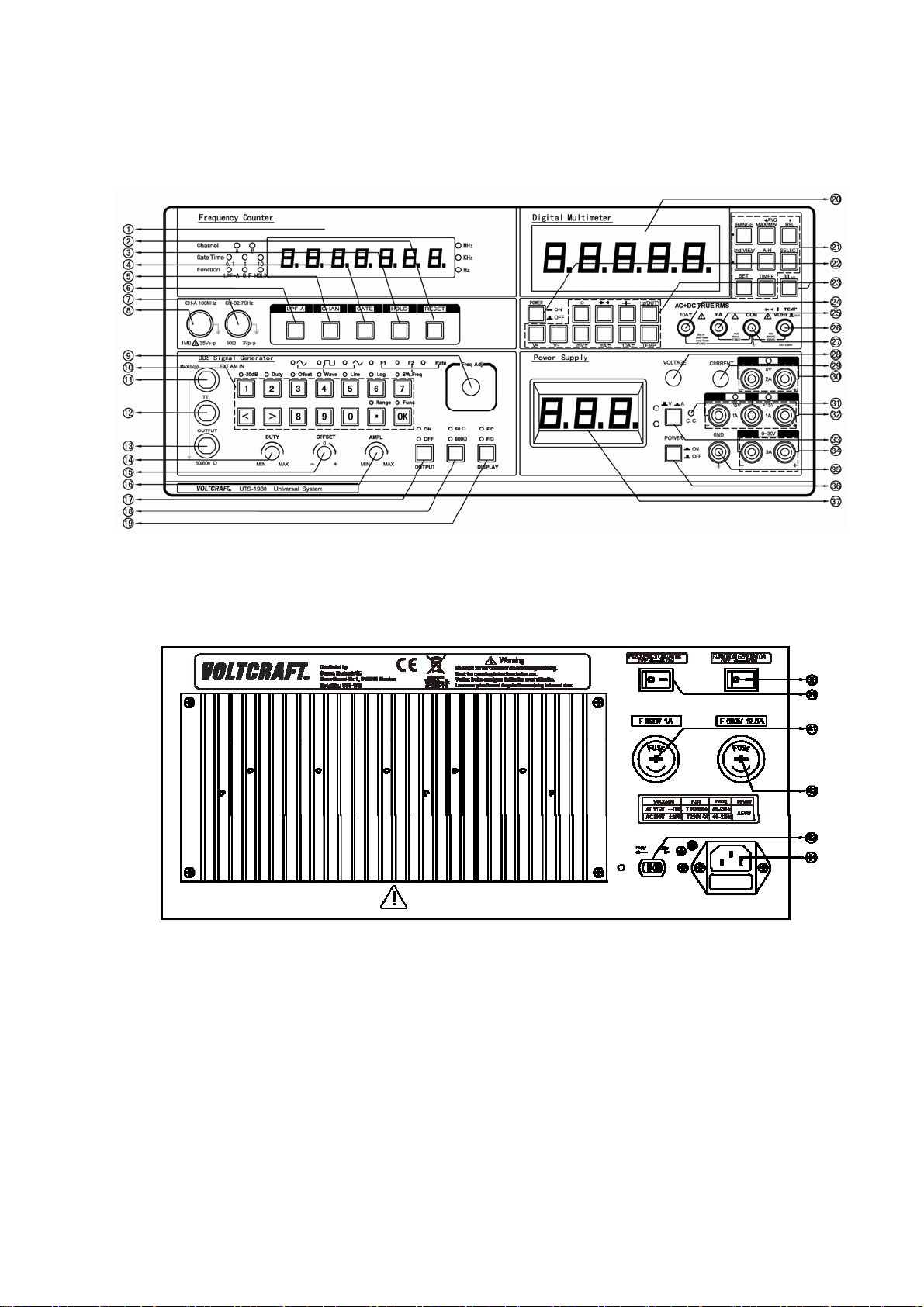
Ⅰ Panel Operation Instruction
Diagram of Front Panel
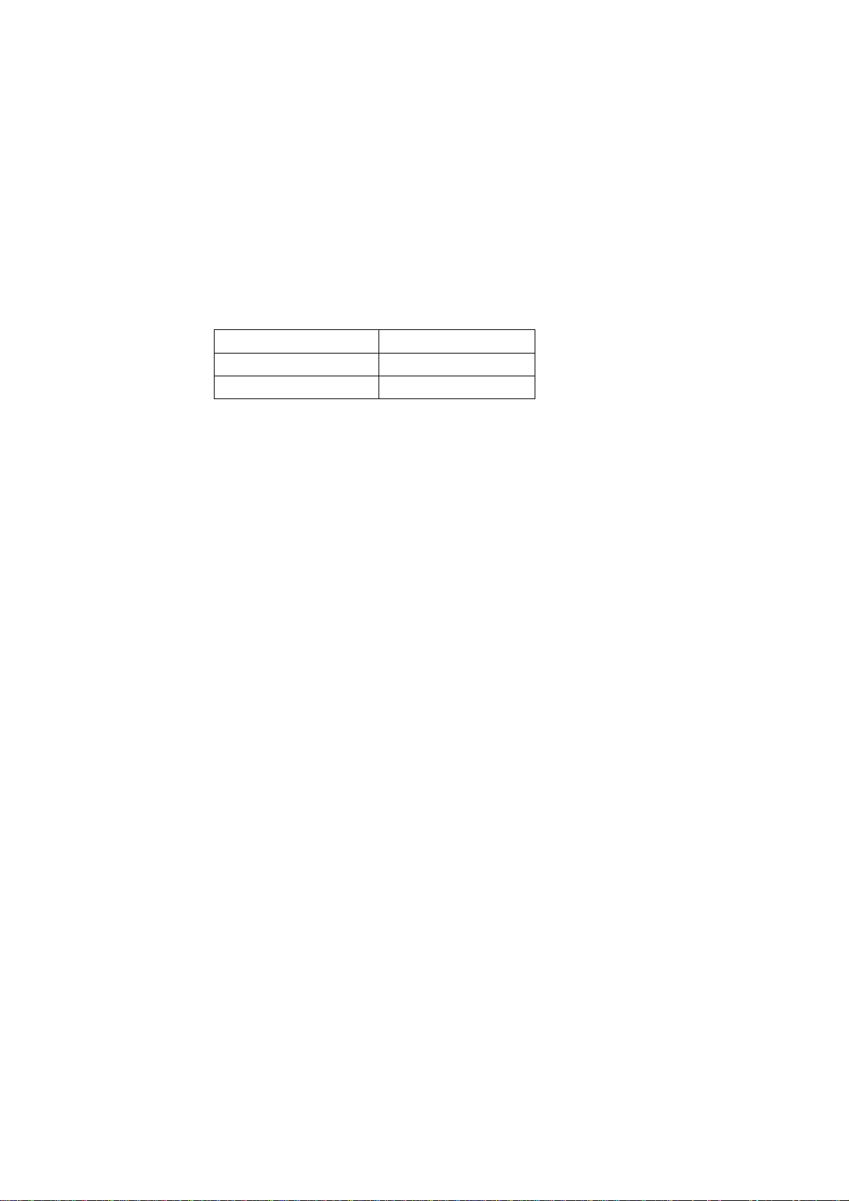
Diagram of Rear Panel Operation Instruction
3
Page 5

○,1 Display window of FC ○,2 Reset of FC
3
○,
Data hold of FC ○,4 Gate time key of FC
5
○,
Channel select key of FC ○,6 Low pass filter key of FC
7
○,
CHB input of FC ○,8 CHA input of FC
9
○,
Frequency variable knob of FG ○,10 Keyboard operation zone of FG
11
○,
Input of ext amplitude of FG ○,12 TTL output of FG
13
○,
Signal output of FG ○,14 Duty variable knob of FG
15
○,
DC offset variable knob of FG ○,16 Amplitude variable knob of FG
17
○,
Output on/off control key of FG ○,18 Output impedance select key of FG
19
○,
Display control key of FG ○,20 Display window of DMM
21
○,
Auxiliary function key zone of DMM ○,22 Power switch of DMM
23
○,
Function keys zone of DMM ○,24 Input terminal of 10A current of DMM
25
○,
Input terminal of mA current of DMM ○,26 Input terminal of voltage and current
measurement
of DMM
27
○,
Common terminal of DMM ○,28 Voltage variable knob of DPS
29
○,
Current variable knob of DPS ○,30 Fix +5V/2A output terminal of DPS
31
○,
Constant current indicator of DPS ○,32 Fix ±15V/1A output terminal of DPS
33
○,
Voltage/current display select switch of
○,34 0~30V/0~3A output terminal of DPS
DPS
35
○,
Grounding terminal ○,36 Main power switch
37
○,
Display window of DPS ○,38 Power switch of FG
39
○,
Power switch of FC
○,40 10A current measurement fuse of DMM
○,41 mA current measurement fuse of DMM ○,42 AC115V/AC230V select switch
43
○,
Power socket
Ⅱ Operation Cautions
1. The instrument has already been done ex-factory inspection strictly. Please first
check whether the instrument is damaged or not during the transportation once
the user opens the package box.
2. Don’t put it in chilly outside. The optimum operating temperature is 5°C~35°C.
3. Don’t expose it at the sunshine or heat source such as stove, for long time.
4. Don’t remove it from heat to chilly environment abruptly or vise versa which will
cause frozen in the inner.
5. Keep it from humidity, water and dust. Otherwise the instrument maybe occur
malfunctions. The optimum relative humidity is 35%~75%.
6. Keep it from the strong shocking environment. Otherwise the instrument maybe
occur malfunctions.
4
Page 6
7. Keep it far away from the high magnetic field and don’t operate it near to
magnetic field. Do not expose it to strong sunshine or ultraviolets directly.
8. Don’t put other objects on it and don’t block the vent holes.
9. Don’t insert lead or pin into the vent holes.
10. Don’t drag it through cables.
11. Don’t put soldering iron on its surface or plastic frame.
12. Don’t invert it for long time during storage and transportation.
13. Check steps before operation:
13.1 Check voltage
Refer to the suitable working voltage as below before the power is on.
Rated voltage Working voltage
AC230V AC230V±10%
AC110V AC99V~121V
13.2 Make sure the fuse should be suitable.
To avoid the circuit damage caused by over current, please use the correct fuse.
Power fuse: AC230V T250V 4A
Shape: 5×20mm
Type: slow-break
DMM fuse: mA current: F 690V 1A
Shape: 10×38mm
Type: fast-break
10A current division: F 690V 12.5A
Shape: 10×38mm
Type: fast-break
*Note: The voltage of the original fuses installed in this product is 690V. In
replacement of the fuse, please choose fuses of voltage higher than 600V.
Ⅲ Frequency Counter (FC) Operation Instruction
1. Technical Specifications
1.1 Freq. measurement range: CHA 1Hz~100MHz
CHB 100MHz~2.7GHz
1.2 Input sensitivity: CHA 50mVrms for sine wave
150mVpp for pulse wave
CHB -13dB(100MHz~1GHz)
-7dB(1GHz~2.7GHz)
1.3 Measurement accuracy: ±(100ns/Gate Time+ Timebase Error+Trigger Error)x
the Frequency of the measured signal
5
Page 7

Note: Time base Error: ≤10ppm(at normal temperature)
Trigger Error≤0.3% when SNR(Signal-to-Noise Ratio)>40dB
1.4 Dynamic Range: CHA 50Vrms~1.5Vrms
CHB -13dBm~+13dBm (100MHz-1GHz)
-7dBm~+13dBm (1GHz-2.7GHz)
1.5 Max. undamage voltage: CHA 35Vpp
CHB 3Vpp
1.5 Input impedance: CHA 1MΩ//40pF
CHB 50Ω
1.6 Time base frequency: 10MHz
1.7 Resolution: ±(100ns/Gate times)x measured signal frequency
2. Basic Operation
2.1 Please check voltage and fuse before the power is on. Turn on main power switch
(○,36)and then turn on FC power switch(○,39)which is on the rear panel of
instrument and then preheat 20 minutes.
2.2 After the power is on, the display window(○,1) of FC indicates “0000000”, the
indicator of CHA will be on. The strobe time is 1s and the indicator of strobe is
on. The indicators of Hold and Low pass filter (LPF-A) will be off.
2.3 LPF-A key(○,6): bandwidth about 100kHz at 3dB, Open LPF (indicator of
LPF-A will be on) to eliminate the HF disturb of the LF signal below 100 kHz
which will make the measured result more reliable.
2.4 Channel key(○,5): It is used to select the measured channel. CHA can be used to
measure 1Hz ~ 100MHz signal frequency. CHB can be used to measure
100MHz~2.7GHz signal frequency.
2.5 For CHA,
a. When frequency is <100 kHz, please turn on the low pass filter (LPF-A).
b. When the amplitude of frequency is >5V, please use external attenuators, such
as oscilloscope-probes.
2.6 Strobe time select key(○,4): It should choose a suitable strobe time if a suitable
resolution is needed. Once the period of the measured signal is more than strobe
time, the measurement time is regarded as a period time of the measured signal.
2.7 Data Hold(○,3): Press it down, the Hold indicator will be on. Then the FC will
stop measurement. The display window will always keep the last measured data
even the signal frequency is changed or test dot is broken. Press Hold again, its
indicator will be off. Then FC re-starts to measure and the display window will
record new frequency measurement data.
2.8 Reset(○,2): It is used to reset the FC.
6
Page 8

2.9 Over-flow indicator(OFL): When the measured signal frequency is over the
range, the over-flow indicator (OFL) will be on, and “ ” will be
on the display window(○,1).
2.10 When both FC and FG are working, both powers need to be turned on. To turn
off FG and keep FC working, please press the DISPLAY key (○,19). After the
“F/C” indicator lights, the display window(○,1) shows the measured frequency
by FC. Then turn off the FG’s power switch.
Ⅵ Function Generator (FG) Operation Instruction
1. Technical Specification
1.1 Waveform characteristic:
1.1.1 Waveform type: sine, triangle, square.
1.1.2 Sine harmonious wave distortion(1Vpp,50Ω): <20kHz -50dBc
20 kHz~1MHz -40dBc
1MHz~10MHz -35dBc
1.1.3 Sine wave distortion: ≤1%(0.1Hz~100 kHz)
1.1.4 Square wave Rise/Fall time: ≤50ns(1MHz, 50Ω, output voltage 5Vpp)
1.1.5 Square overshot: ≤5%
1.1.6 Square duty cycle range: 15%~85%(≤10kHz)
1.1.7 Waveform asymmetry: <1.5%+20ns of period(≤100 kHz)
1.1.8 Triangle linearity: <1%(≤100 kHz)
1.2 Frequency characteristic:
1.2.1 Frequency range: Sine wave 0.1Hz~10 MHz (50Ω)
Square wave 0.1Hz~1 MHz(200mVpp~10Vpp,50Ω)
Triangle waveform 0.1Hz~1MHz
1.2.2 Frequency accuracy: ±(5×10⁻⁵+80mHz)
1.2.3 Frequency stability: 50ppm(long term)(Generally, calibration at 1 time/year)
1.2.4 Max. Resolution: 0.01Hz
1.3 Amplitude Characteristic:
1.3.1 Output amplitude range: 100mVpp~20Vpp(High impedance)
1.3.2 Amplitude flatness: ±5% (in 0.1Hz~10MHz at 50Ω)
1.3.3 Output impedance: 50Ω±10%/600Ω±10%
1.4 Overshot Characteristic:
1.4.1 DC offset range: Vpp AC+DC: ±10V(600Ω); ±5V(50Ω)
1.5 Sweep Frequency Characteristic:
1.5.1 Type: Linearity or Log
1.5.2 Sweep frequency: Negative or positive
1.5.3 Sweep range: 1Hz~10MHz
7
Page 9

1.5.4 Sweep freq velocity: 0.01Hz~100Hz
1.6 Attenuation:
1.6.1 Attenuation: -20dB
1.6.2 Error: ±3%(open circuit)
1.7 External Amplitude Input:
1.7.1 Input impedance: 1kΩ
1.7.2 Ext amplitude freq range: 0.1Hz~20kHz(the output impedance of modulation
source is 50Ω)
1.7.3 Ext amplitude sensitivity: 0~5Vpp±2%
1.7.4 Amplitude depth: 0~100%
1.8 TTL Output:
1.8.1 Output amplitude: “0” level ≤0.3V; “1” level ≥3.3V
1.8.2 Output impedance: 50Ω ±10%
2. Panel Layout
13
○,
2.1 There are 3 ports on panels, signal output port(
port(
12
○,
)and ext amplitude signal input port(○,11).
), TTL synchronized output
2.2 There are four variable knobs on panels, freq variable knob(○,9)to adjust output
frequency of signal and change setting of sweep frequency parameter, Duty
variable knob(○,14)used to adjust duty ratio of square wave, DC offset variable
knob(○,15) used to adjust DC offset of signal and Amplitude variable knob
(○,16) used to adjust amplitude of the output signal.
2.3 There are 14 keys on keyboard operation zone: 10 number keys (number【0】~
【9】);2 direction keys(left【<】, right【>】); 1 decimal point(【.】); 1
OK key(【OK】). There are three function keys: One is signal output switch
(○,17)which is used to control whether FG output signal or not. Press it, FG
output is switched between on/off state. The indicator above the key is
corresponding to the FG output state; the secondly is output impedance key
(○,18), the indicator above the key is corresponding to FG output impedance.
Press it, FG output impedance will be switched between 50Ω and 600Ω; The
19
○,
thirdly is display function switch key (
function of window(
1
○,
). When the F/C indicator is on, the display window will
) which is used to change the display
be used to display the measured frequency of the FC and when F/G indicator is
on, the display window will be used to display the frequency of the FG. Once the
power is on, the default state of the display window(○,1) is to display the
frequency of the FG.
2.4 The secondary function key: Once the power is on, the indicator “FUNC” above
key 【OK】 will be on. The below keys, keys【1】~【7】, decimal point
【.】and 【OK】, are used for the second functions which are indicated
above the keys,
3. Basic Operation
8
Page 10

3.1 FC display window(○,1)displays frequency. 6 digits of FG.
3.2 The frequency can be adjusted by hand wheel or enter numbers directly.
Once the power is on, the default output frequency is 1 kHz. At the time,
number “1” is flashing. Remove the flashing number horizontally by【<】
and【>】and the flashing number can be changed through rotating the
hand wheel. Press【 .】, indicator “Range” above 【.】 will be on. Then the
frequency unit indicator will be flashing to indicate which unit should be
applied to the value shown on the display window (○,1). Rotate the hand
wheel; the value will be changed as ×10 times or 1/10 times each time.
Press 【.】 again, the “Range” indicator will be off and re-start adjustment
mode by hand wheel. Press【OK】, “Func” indicator will be off, frequency
on window is cleared and enter into state of entering numbers directly. All
the entered numbers will be flashing and they are can be deleted freely
from left to right through【<】, which can correct the numbers. And also
units, such as MHz, kHz, Hz, can be selected through【>】. Press【OK】
again after entering numbers, the key of “Func” will be on; the signal
frequency will be displayed on frequency window.
3.3 The operation of Secondary function key.
Once the power is on, the “Func” indicator above 【OK】will is on. Parts
of keys are corresponding to the secondary functions which are indicated
on panel.
【-20dB】: Press【1】,the indicator “-20dB” will be on. The attenuation
amplitude of output signal is -20dB of the original output amplitude.
Press the key again, the indicator “-20dB” will be off, the amplitude of
output signal will not be attenuated.
【Duty】: Press【2】,the indicator above “Duty” will be on. Adjust the
Duty cycle variable knob(○,14) to change duty ratio of square wave.
Press the key again, the indicator “Duty” will be off, the output duty cycle
of square wave is 50%. At the time, the Duty variable knobs(○,14)do not
work.
【Offset】:Press【3】,the indicator above “Offset” will be on. Adjust the
DC offset variable knob(○,15), DC offset of output waveform can be
adjusted. Press the key again, the indicator “offset” will be off, the output
waveform is back to normal. At the time, the DC offset variable knob
(○,15)won’t be work.
【Wave】:When the power is on, the default output of FG is sine wave.
The ”Sine” indicator will be on. Once press number 【4】 each time,
output waveform of FG will be switched between sine, square and triangle
in turn.
9
Page 11

【Line】:Press【5】,the “Line” indicator will be on, the FG is in the state
of linearity sweep frequency mode. F1 indicator is on above number key
【7】, and then the first frequency of linearity sweep frequency can be set.
Press【7】, indicator “F2” will be on, then the end frequency can be set.
Press【 7】again, indicator “Rate” is on, and then sweep frequency velocity
can be set. Press number key【5】,indicator “Line” will be off. All the
indicators above【7】are off, FG will quit sweep frequency mode.
【Log】: Press number key【 6】,indicator “Log” will be on. FG is in the
state of log sweep frequency mode. At the same time, indicator “F1” will
be on. Then the first frequency of log sweep frequency can be set. Press
【7】,indicator “F2” will be on. At the same time, the end frequency of
log sweep frequency can be set. Press【7】 again, indicator “Rate” will be
on, and then the velocity of sweep frequency can be set. Press number key
【5】,indicator “Log” will be off. All the indicators above 【7】 are off;
FG will quit the sweep frequency mode.
【Func】:When the power is on, the indicator “Func” above【OK】is on,
it is in the state of function setting. Press【 OK】,the indicator “Func” will
be off. At the time, the window is cleared up and enters the state of
entering number.
【Range】:Press【 .】, the indicator “Range” will be on. Then the indicator
for frequency unit (MHz or KHz or Hz) will flicker. Rotate the hand
wheel(○,9),the value will be changed as ×10 times or 1/10 times. Press
【.】again, the indicator “Range” will be off and it goes again in mode of
frequency adjustment by the “Freq.Adj” knob.
Ⅴ DC Power Supply (DPS) Instruction
1. Technical Specification
1.1 CH1 output(output terminal ○,34)
1.1.1 Output voltage: 0~30V
1.1.2 Output current: 0~3A
1.1.3 Ripple and noise: ≤1mVrms
1.1.4 Load effect: 0.1%+5mV
1.1.5 Source effect: 0.1%+5mV
1.1.6 Max. Output current: ≥3.2A
1.1.7 Display accuracy: Voltage ±1%+2 digits; Current ±2%+2 digits
1.2 CH2 output(output terminal ○,32)
1.2.1 Output voltage: fixed ±15V±2.5%
1.2.2 Output current: 1A
1.2.3 Ripple and noise: ≤2mVrms
10
Page 12

1.2.4 Load effect: 0.1%+50mV
1.2.5 Source effect: 0.1%+30mV
1.2.6 Max. Output current: ≥1.2A
1.3 CH3 output(output terminal ○,30)
1.3.1 Output voltage: fixed +5V±3%
1.3.2 Output current: 2A
1.3.3 Ripple and noise: ≤2mVrms
1.3.4 Load effect: 0.1%+70mV
1.3.5 Source effect: 0.1%+30mV
1.3.6 Max. Output current: ≥2.2A
2. Basic Operation
2.1 Please check the fuses before the power is on. Disconnect all the cables
29
connected to the output terminals. Adjust Current knob(○,
)clockwise to
maximum to set the current to the max output value.
2.2 Press Power switch (○,
36
) . DPS window (○,37) will display output
current/voltage value of CH1(output terminal ○,34). The indicator of CH2
(output terminal ○,32)& CH3(output terminal ○,30)will be on. And there will
be outputs in the three channels of the DPS.
2.3 Display window(○,37)can display voltage value or current value. When the key
33
○,
is not pushed down, the display window(○,37)will show the output voltage
value of CH1(output terminal ○,34). When the key is press down, the display
window(○,37)will show the output current value of CH1(output port ○,34).
2.4 Voltage variable knob(○,28)is used to change CH1(output port ○,34) output
voltage value. Once adjust it clockwise, the voltage value will be bigger
gradually and vise versa. Please note that there is no stopper for this voltage
variable knob(○,28). Above 30V, the knob still can be turned clockwise, but the
value of output voltage will not increase. Current variable knob is used to set
CH1(output port ○,34)max. current value. Adjust it clockwise, the current
value will be bigger gradually and vise versa.
2.5 Once the value of the output current is higher than the set max. current output
value, CH1(output port ○,34)will go inot the constant current state. At this time,
the indicator C.C will be on. The extra current will cause the voltage down.
2.6 Warning: For CH2 outputs, if using the left blue terminal of the -15V/1A output
with the right red terminal of the +15V/1A output, you can get a 30V/1A output!
But the +30V/1A output cannot work together with the +15V/1A output and
-15V/1A output, otherwise the values of the output voltage and current will be
reduced.
11
Page 13

Ⅵ Digital Multimeter (DMM) Operation Instruction
1. Safe Operation Rules
1.1 It is suitable for the over voltage standard of IEC 61010 CAT II 600V
1.2 Please check whether the shell, test lead and isolating layer are perfect
and without any damage before use it.
1.3 Please check the voltage to confirm the meter is in good working state.
Otherwise, please contact to repair immediately instead of using it.
1.4 Please use the terminals and select divisions of function and range
correctly when measure it.
1.5 Please don’t measure the voltage when the test lead is inserted into the
current terminal.
1.6 Please don’t use voltage more than the indicated rated voltage (Refer to
the sign ) between any terminal and earth.
1.7 When undertaking measurement, keep your fingers behind the guards’s
plant on the test leads or probes. Please care for the voltage more than
33Vrms AC or 70VDC in normal condition to avoid electric shock.
1.8 Disconnect the power and discharge all high-voltage capacitors before
testing in resistance, continuity and diode functions.
1.9 Please don’t store and operate the meter under the environment of high
temperature, high humidity, flammable and strong magnetic field.
1.10 The correct procedure to turn off the DMM is to turn off the DMM
power switch ○,
22
firstly before turn off the main power switch○,
you turn off the main power switch directly to turn off the DMM, when
you start the DMM again, the LCD display may show messy codes or a
pure white screen. At the time, turn off the DMM power switch and turn
on the DMM again, the messy codes or white screen will disappear.
2. Panel Instruction
2.1 Refer to Table 1 for terminals(Chart 1)
Chart 1.
Table 1
Terminal symbol Function
36
. If
12
Page 14

COM For all the common terminals
mA mA current input terminal
10A 10A current input terminal
VΩHz
2.2 Refer to Table 2 for Function keys(○,
Voltage, resistance, continuity, diode, capacitor, frequency,
temperature measurement and square wave output terminal.
23
)
Chart 2.
Table 2:
Key Description Key Description
V DC voltage Test for diode, Continuity
V AC voltage Capacitor
mV DC/AC mV voltage Hz/DUTY Freq/Duty ratio
mA DC/AC mA current TEMP Temperature
10A DC/AC 10A current
OUT Square wave output
Ω Resistance POWER Power switch
2.3 Auxiliary function keys(○,
21
)
When press these keys, the corresponding symbol will be on LCD alongside a
buzz.
13
Page 15

Chart 3.
Notice: Because this DMM has complicated functions, when pressing these keys,
the meter has to make logic judge which takes some time. Please make
measurements after the display is stable.
2.3.1【SELECT】
● Press【SELECT】to select the needed measurement state.
● When the DMM output square wave, please press 【SELECT】 to change duty
of square wave signal. Press it each time, it will change 1% (The variable
change 1%~99%).
2.3.2【RANGE】
● Once the power is on, the DMM is in AUTO range state. Press【RANGE】can
select your measurement range. Press it quickly to select the range you needed.
And press it once, it change a range.
● When the【SET】key is in operation,【RANGE】will be change as【▲】(moving
up). Press it to move setting digits up.
● Press【RANGE】lasting more than 2s,it will be back to AUTO range.
2.3.3【MAX/MIN】
● Press【MAX/MIN】, it will be dynamic record mode which can capture and
record MAX, MIN and MAX-MIN from variable input signal and calculate AVG
of all readings. Press 【MAX/MIN】 to display MAX/MIN/(MAX-MIN)/AVG
in sequence on slave display.
● Press【MAX/MIN】lasting more than 2s,it will be back to normal mode.
● In state of MAX/MIN,the record time is 36 hours.
● After run【SET】,【MAX/MIN】will be change as【◄】(moving left). Press
it to move setting digits left.
2.3.4【A-H】
● Press 【A-H】, the DMM will enter the Automatic Peak Hold mode and “A—H”
appear on display screen.
● This function can hold the displayed value. When the actual measured value is
higher than the held value, the displayed value will be automatically updated to
the new peak value alongside a buzzer.
● Press the button again, it will display “PH+/PH-”. PH+ means to hold the
positive peak value and PH- means to hold the negative peak value.
“PH+/PH-“ only works in DC voltage and current tests.
14
Page 16

● Press【A-H】lasting more than 2s to exit Peak Hold mode and return to normal
mode.
2.3.5【2nd VIEW】
● In Table3 measuring state, press 【2nd VIEW】to switch and display each
function in slave display.
Table 3:
Function key
position
V
V
mV
Hz/DUTY
OUT
Measure state Master display
ACV+ Hz ACV Hz/ %/ %/ ms/ ms
AC dBm+Hz AC dBm Hz/ACV
(ACV+DCV) +Hz ACV+DCV Hz/ACV
dBm+Hz dBm Hz/ACV/DCV/ACV+DCV
ACmV+ Hz ACmV Hz/ %/ %/ ms/ ms
dBm+Hz dBm Hz/ACmV/DCmV/ACmV+DCmV
Hz Hz %/ %/ ms/ ms
OUT
Press【2nd VIEW】
to change output
signal frequency
Slave(switch them by pressing
【2nd VIEW】)
Press【SELECT】to change duty of
output signal
● Press【2nd VIEW】to select output frequency of square wave when the DMM is
in Square wave output mode:
0.5000Hz/1.0000Hz/2.0000Hz/10.000Hz/50.000Hz/60.24Hz/74.63Hz/100.00Hz
/151.5Hz/200.00Hz/303.00Hz/606.1Hz/1.25kHz/1.6660kHz/2.5kHz/5.0000kHz
● Press【2nd VIEW】lasting more than 2s,the output square wave will return to
default 606.1Hz and 50% duty cycle.
● When the 【SET】 key is in operation,the key 【2nd VIEW】will be changed
as 【▼】(moving down). Press it to move setting digits down.
2.3.6【REL】
● Press【REL】,it will be in state of relative measurement function and at the same
time, symbol “REL▲” will be displayed. It indicates the different between
measuring value and reference value which means press【REL】,it will treat
current measurement value as reference value(Ref). After that, REL▲ or REL%
is on the reading of master display and reference value on slave display. Press
【REL】 again, the measured value will be on slave display again.
● In the state of【REL】,Press【SELECT】to select “REL▲” or “REL%”. And at
the same time, “REL%” and “REL▲” will be on screen.
REL▲=measured value- reference value
REL%=(REL▲/ REL)×100%
● After run【SET】,【REL】will be change as【►】(moving right). Press it, the
pre-setting value can be removed towards right.
15
Page 17

● Press 【REL】lasting more than 2s, it will be back to normal .
● Setting of relative measured value:
○,1 Press【RANGE】to select the suitable range.
○,2 Press【SET】once and press【SELECT】twice, it will be in state of relative
value setting and at the same time【▲】,【▼】,【◄】and【►】are workable.
○,3 After setting, please press【SET】to confirm it.
2.3.7【SET】
● When the 【SET】 key is in operation, the 【RANGE】 keyn is used as a moving
up key ( ), the 【2nd VIEW】 key as a moving down button ( ), the
【MAX/MIN】as a moving left button ( ), and 【REL】as a moving right ( ). In
this case, the 【RANGE】,【2nd VIEW】, 【MAX/MIN】 and 【REL】’s original
functions are disabled. keys can be used to enter and adjust the
setting values.
3. Display(○,20)
Chart 4.
The following Table 4 gives descriptions of the symbols displayed on the LCD.
Table 4:
Number Symbol Description
1 Bar graph : display bar graph of the current input signal
2,3,15 - Negative sign
4 Out Square wave output
5 Hi High frequency measurement or thermocouple
temperature measurement
6 Low Battery
7 Diode test, Continuity test
8 REL▲ REL% Symbols of relative measuring value and relative percent
measurement value
9,17 AC AC+DC DC AC, AC+DC, DC voltage or current
10 PH+ PH- Positive peak, negative peak
16
Page 18

11 A─H Automatic Peak Hold
12 AVG Record average value
13 AUTO Auto range
14 MAX MIN MAX-MIN MAX reading, MIN reading, MAX-MIN reading
18 mV/V/mA/A Voltage and current units on slave display
19 Hz/kHz/MHz/Ω/kΩ/MΩ Frequency and resistance units on slave display
20 % % ms ms Duty cycle unit and pulse width unit
21 nF/μF Capacitance unit: nF or μF
22 mV/V/mA/A Voltage and current unit on primary display
23 dBm Level unit: dBm
24 Hz/kHz/MHz/Ω/kΩ/MΩ Frequency and resistance unit on primary display
25,16 Temperature unit: Celsius and Fahrenheit
OL Over Range indication (as below picture)
4. Special Function
4.1 Set measurement time
● Except diode, frequency and square wave output, the other functions division
can be used to set measure time.
● The displayed time style is “0.00.00”(on slave display),the first number as hour,
second and third as minute and the fourth and fifth as second. The max time is
“9.59.59”。
● Press【TIMER】to enter the mode of time setting(“0.00.00” on slave display);
Press 【SELECT】 to set time. At the time, the last number of time “0” is
flashing. Press【◄】 and 【►】to set time numbers and press【▲】and【▼】
to set time value. Press 【TIMER】again to confirm the set time. From now on,
the measure begins to count time.
● During the set period, it does measurement normally. Once the time counting
is finished, it will buzz continuously.
● Once the clock function is activated, the set time and time counting won’t be
affected by the function changes and operations. Only when【A-H】is activated,
the time counting will stop and the counted time will be cleared. If you need to
restart time counting again, repeat the above operations.
17
Page 19

4.2 Set upper and lower limits for measurement
● Procedures to set upper and lower measurement limits.
○,1 Upper limit set: Turn on the power. Select the functions state and select
suitable range with 【RANGE】. Press【SET】to run setting mode ( “ ”
will be on slave display). Press【◄】,【►】,【▲】 and 【▼】to set the upper
limit value. Press【SET】to confirm it.
○,2 Lower limit set: Turn on the power. Select the functions state and select
suitable range with 【RANGE】. Press 【SET】 and then 【SELECT】to
run setting mode ( “ ” will be on slave display). Press【◄】,【►】,
【▲】and【▼】to set the lower limit value. Press【SET】to confirm it.
● Measurement can be carried out after setup of upper and lower limits is finished.
There are three kinds of display mode according to the measurement results:
○,1 If the measured value is higher than the upper limit, the measured value will
be on the master display and “ ” will be on the slave display.
2
○,
If the measured value is less than the lower limit, the measured value will be
on the master display and “ ” will be on the slave display.
○,
3
If the measured value is between upper and lower limits, the measured value
will be on the master display and “ ” will be on the slave display.
4.3 Analog Bar Graph Display
The Function of bar graph is imitating the analog needle of meter but without
overshoot, and refreshes 40 times per second. Because the graph responds 10
times faster than the digital display it is useful for peak value test, zero
calibration and observing rapid changing signals. The bar graph has 20 segments.
The number of the shown segments at a moment is relative to the proportion of
the measured value to the full-scale value of the selected range. One segment
represents 4000counts except the situation that the DMM is in the relative
measurement mode. The polarity is indicated at the left of the bar graph, (“+”
polarity is not indicated).
4.4 Square wave output
The square wave output is a useful function. The frequency and duty cycle are
adjustable, which helps users to do a lot of tests, such as the PWM (Pulse Width
Modulation) output, adjusting the voltage control, timer to control circuit , clock
syntherization, etc.
5. Instructions for Measuring Functions
5.1 DC Voltage measurement
Warnings: the measured DC voltage must not
exceed DC 600V because the high voltage
standard of this DMM is IEC 61010 CAT II 600V!
18
Page 20

● Press【V 】and it will be in DC voltage
measurement .
● There are 3 measurement modes: DCV,DCV+ACV
and dBm. Press【SELECT】to select one of them.
Chart 5 DC Voltage Measurements
● When the power is on, the measurement will be on AUTO state. Press【RANGE】
to select range manually: 8.0000V/80.000V/600.00V
● According with the user’s requirements, press(【REL】 【MAX/MIN】 and
【2nd VIEW】)to do test and record. All of them will be on slave display.
● Insert the red test leads into “VΩHz” terminal and the black test lead into “COM”
terminal. Contact the test points with the test leads. Please refer to Chart 5. The
measured value and relative symbols will be on master and slave screen at the
same time. Please refer to Table 5:
Table 5:
State(Press【SELECT】to select state)
DCV DCV
DCV+ACV DCV ACV/Hz
dBm dBm Hz/DCV/ACV/DCV+ACV
Master
isplay
Slave Display(switch between them by
pressing【2nd VIEW】)
● In dBm test,the default impedance is 600Ω. Press【RANGE】to change the load
impedance and the selectable values are as below: 4Ω, 8Ω, 16Ω, 32Ω, 50Ω, 75Ω,
93Ω, 110Ω, 125Ω, 135Ω, 150Ω, 200Ω, 250Ω, 300Ω, 500Ω, 600Ω, 800Ω, 900Ω,
1000Ω and 1200Ω. In dBm measurement mode, the decimal point of dBm is
fixed between the second and third digits and 【REL】, 【MAX/MIN】and 【P-H】
are disabled.
5.2 AC Voltage measurement
Warning: The measured voltage must not exceed AC 450V because the high
voltage standard of this DMM is IEC 61010 CAT II 600V!
Note: Before tests on low voltage, please connect the test leads in
short-circuit and press【REL】to make zero for a better accuracy!
● Press【V 】 to enter AC voltage function
● AC voltage has three states of ACV,ACV+Hz
and dBm. Press【SELECT】 to choose one of them.
When the power is on, the measurement is
in AUTO state. Press【RANGE】 to select
suitable range. The selectable ranges are as
below: 8.0000V/80.000V/450.00V
● Press (【REL】,【MAX/MIN】 and
【2nd VIEW】)to do relative test and
record. All of them can be on slave
19
Page 21

display.
● Insert red test leads into “VΩHz” and
black into “COM” and contact the test
point via lead’s pin. Please refer to
Chart6 for the measurement mode. Chart 6. AC Voltage Measurement
The measured values and relative symbols will be on master and slave display at
the same time. Please refer to Table 6:
Table 6:
Press【SELECT】to choose state
ACV ACV
ACV+Hz ACV Hz/ %/ %/ ms/ ms
dBm dBm Hz/ACV
Master
isplay
Slave Display(switch between them by pressing
【2nd VIEW】)
● In dBm test,the default impedance is 600Ω. Press【RANGE】to change the load
impedance and the selectable values are as below: 4Ω, 8Ω, 16Ω, 32Ω, 50Ω, 75Ω,
93Ω, 110Ω, 125Ω, 135Ω, 150Ω, 200Ω, 250Ω, 300Ω, 500Ω, 600Ω, 800Ω, 900Ω,
1000Ω and 1200Ω. In dBm measurement mode, the decimal point of dBm is
fixed between the second and third digits and 【REL】, 【MAX/MIN】and 【P-H】
are disabled.
● Notes: If a ACV measuring is chosen and the two test leads are short-connected,
it takes a long time until the value goes down. This process is normal. This is
because that the high impedance inside takes some residual voltage. In this
process, the filtering capacitors slowly discharges to keep the potential. But this
does not affect the ACV accuracy. When the displayed value is not down to zero
yet and an ACV test is done at the time, the value measured will still be accurate.
5.3 AC/DC milli voltage measurement
Warning: The measured voltage
should not exceed DC 250V or AC
peak to peak voltage at the input
terminal!
● Press【mV 】to enter the function of
AC/DC milli voltage measurement.
● It has three modes: DCmV,ACmV+
Hz,dBm. Press【SELECT】to select
one of them.
● When the power is on, it will be in
AUTO state. Press 【RANGE】 to
select the suitable ranges manually.
20
Page 22

The selectable ranges are:
80.000mV/800.00mV.
● Press【REL】, 【MAX/MIN】and Chart 7. AC/DC mV Measurement
【2nd VIEW】)to do the relative test or record which will be in slave display.
● Insert red test leads into “VΩHz” and black into “COM” and contact the test
point via lead’s pin. Please refer to Chart 7. for the measurement mode. The
measured values and relative symbols will be on master and slave display at the
same time. Please refer to Table 7:
Table 7:
Press(【SELECT】to choose state)
DCmV DCmV
ACmV+Hz ACmV Hz/ %/ %/ ms/ ms
dBm dBm Hz/ACmV/DCmV/DCmV+ACmV
Master
isplay
Slave Display(switch between them by pressing
【2nd VIEW】)
● In dBm test,the default impedance is 600Ω. Press【RANGE】to change the load
impedance and the selectable values are as below: 4Ω, 8Ω, 16Ω, 32Ω, 50Ω, 75Ω,
93Ω, 110Ω, 125Ω, 135Ω, 150Ω, 200Ω, 250Ω, 300Ω, 500Ω, 600Ω, 800Ω, 900Ω,
1000Ω and 1200Ω. In dBm measurement mode, the decimal point of dBm is
fixed between the second and third digits and 【REL】, 【MAX/MIN】and 【P-H】
are disabled.
● Note: In order to reduce the attenuation effect to the small input signal and
enhance the accuracy, the resistance is very big for AC mV auto range, more
than 1000MΩ. If the probes is connected but in open status and no signal is
applied on the input terminal, it will normally be over the range. At the time,
there will be “OL” shown in the display with the overload buzzer keeping
buzzing. The slave display at the time is showing the frequency of the
surrounding interference signal on the open-circuit.
In milli voltage measurement mode, in order to obtain DC+AC function, the
●
input terminal of ADC does not employ coupling capacitor. Therefore, never
apply a voltage over double value of DC or AC voltage of the rated value of this
range
5.4 AC/DC Current Measurement
Warnings for AC/DC Current measurement
To avoid damage to the meter or injury and never attempt an in-circuit current
measurement when the fuse is blown, or when the voltage between open circuit
and the ground is 600V.
Do not make 20A current measurements for longer than 15 seconds.
Exceeding 15 seconds may cause damage to the meter and/or the test leads.
21
Page 23

To avoid damage to the meter, check the meter’s fuse before tests.
Before current measurement, turn off the DMM power supply, discharge the
high voltage capacitance.
Do not place the probes in parallel with a circuit or component when the leads
are plugged into the current terminals.
Do not test voltage when the test leads are plugged in “mA” or “10A” terminals.
Use the proper terminals, functions, and ranges for your measurement.
5.4.1 DC/AC mА Current Measurement
Note: Before tests on low AC mA current, please have the two test leads in
open-circuit status and press【REL】to make zero for a better accuracy!
● Press【mA 】to enter the function of
AC/DC milli current measurement.。
● It has four modes: DCmA,ACmA ,
ACmA+Hz,DCmA+ACmA. Press
【SELECT】to select one of them.
● When the power is on, the
measurement mode will be in AUTO
state. Press 【RANGE】 to select the
suitable ranges. The selectable ranges
are: 80.000mA/800.00mA.
● Press【REL】, 【MAX/MIN】and
【2nd VIEW】)to do the relative
test or record Chart 8. AC/DC mA Measurement
which will be displayed in slave display.
● Insert the red test leads into “VΩHz” terminal and the black test lead into
“COM” terminal and contact the test points with the test leads. Please refer to
Chart 8. for the measurement mode. The measured values and relative symbols
will be on master and slave display at the same time. Please refer to Table 8:
Table 8:
Press 【SELECT】to Choose State Master display Slave display
DCmA DCmA
ACmA ACmA
ACmA+Hz ACmA Hz
DCmA+ACmA (DC+AC)mA ACmA
5.4.2 AC/DC Ampere Current Measurement
22
Page 24

Note: Before tests on small AC current, please have the two test leads in
open-circuit status and press【REL】to make zero for a better accuracy!
Do not make 20A current measurements for longer than 15 seconds.
Exceeding 15 seconds may cause damage to the meter and/or the test leads.
● Press【10A 】 to enter the function.
● It has three states of DCA, ACA, ACA
+Hz, DCA+ACA. Press【SELECT】
to select one of them.
● When the power is on, the
measurement mode will be in AUTO
state. Press【RANGE】to select the
suitable ranges manually. The
selectable ranges are
8.0000A/10.000A
● Press【REL】, 【MAX/MIN】to do
the relative test or record which will be
in slave display.
● Insert the red test leads into “10A”
terminal and the black test lead into
the “COM”terminnal and contact the
test points with the test leads.
Please refer to Chart 9. Chart 9. AC/DC Ampere Measurement
for the connection mode.
The measured values and relative symbols will be on the master and the slave
display at the same time. Please refer to Table 9.
Table 9:
Press 【SELECT】to Choose State Master display Slave display
DCA DCA
ACA ACA
ACA+Hz ACA Hz
DCA+ACA (DC+AC)A ACA
5.5 Resistance Measurement(Ω)
Warning: To avoid damage to the meter or to this equipment under test,
disconnect circuit power and discharge all high-voltage capacitors before
measuring resistance. Use the DC function to confirm that the capacitor is
discharged.
Note: In measuring low resistance, the resistance of the test leads may cause
23
Page 25

an error of 0.1Ω~0.5Ω in the test results. To avoid this error, first short the
test leads, next press 【REL】key. The master display will be zero and the
slave display displays the resistance of test lead. .
● Press【Ω】 to the function of resistor
measurement.
● The measurement has three modes:
noraml (Ω) , Continuity ( ) and
hi-impedance(Hi). Press
【SELECT】to select one of them.
● Normal resistance check(Ω)
○,1 When the power is on, the measurement mode will be in
AUTO state. Press【RANGE】to
select the suitable ranges manually. The selectable
ranges are: 800.00Ω / 8.0000kΩ
/ 80.000kΩ / 800.00 kΩ / 8.0000MΩ
/ 80.000MΩ
Chart 10. Resistance Measurement
○,2 Press【REL】, 【MAX/MIN】to do the relative test or record which will be
in slave display.
○,3 Insert the red test leads into “VΩHz” terminal and the black test lead into
“COM” terminal and contact the test points with the test leads. Please refer to
Chart10 for the connection mode. The measured values and relative symbols
will be on the master and slave display at the same time. Please refer to Table
10.
Table 10:
Measurement state Master display Slave display
Ω Ω/kΩ/MΩ Relative to MAX/MIN and REL
● Continuity test( )
Press【SELECT】to select the “ “ range. Once the measured resistor is less than
50Ω, it will buzz. Please note that continuity can only be judged by the buzzer
sound and the display is no meaning at the time.
● High resistance measurement(Hi)
This function is used to measure the resistance above 80MΩ.
Press 【SELECT】 SELECT button to select “HiΩ” range. The master display
will display “Hi”.
A single range is 1000.0MΩ. If the testing points resistance falls below 10MΩ
and above 8000.0MΩ, “OL” will appear on the display.
24
Page 26

5.6 Capacitance Measurement( )
Warning: To avoid damage to the meter or the testing equipments disconnect circuit
power and discharge all high voltage capacitors before measuring capacitance. Use the DC
function to confirm that the capacitor is discharged.
Notes:
Some capacitors have polarities. In measuring polarities capacitors, touch the red
test lead to the positive polarity and the black test lead to the negative polarity.
In measuring low capacitance, the resistance of the test leads may cause an error
in the test results. To avoid this error, first short the test leads, next press REL△
button. The master display will be null and the secondary display displays the
resistance of test lead. Measure the to-be tested resistance and the result will be
displayed on the master display.
Capacitor is capable of storing electric charge. When testing capacitance, only the
value on a stable display is the correct result.
Press【 】to enter capacitor measurement
function.
● When the power is on, it will be in
AUTO state. Press【RANGE】to select
the suitable range manually:
1.0000nF/10.000nF/100.00nF/1.0000
μF/10.000μF/ 100.00μF.
● Insert the red test leads into “VΩHz” terminal
And the black test lead into “COM” terminal
and contact the test points with the test leads.
Please refer to Chart11 for the connection mode.
The measured values and relative
symbols will be on the master and slave
displays at the same time. Please refer to Table 11.
Table 11:
Measurement State Master Display Slave Display
nF/μF
Chart 11. Capacitance Measurement
Relative to MAX/MIN and REL
5.7 Measurements of Frequency(Hz)
● Press【Hz/DUTY】to enter the function of frequency measurement.
● It has three states of NORMAL and HiHz. Press【SELECT】to choose one of
them.
● In the normal measurement mode , the
25
Page 27

frequency range is as follows :
999.99Hz / 9.9999kHz/ 99.999kHz/
999.99kHz/ 5.0000MHz. When test it,
it will be always in state of auto
range.Then frequency range is
0.5Hz~5MHz.
● In the state of HiHz,the frequency is
9.9999MHz/99.999MHz/999.99MHz.
Use other high frequency accessories
to measure frequency above 10MHz.
During measurement, it will be always
in auto measurement
Mode. The frequency range is 8MHz
~1000MHz in such state. Also, the Chart 12. Frequency Measurement
Master and slave display will be
combined into a 10-digit display. The
former displays the higher 5 digits of
and the latter displays the lower 5
digits, i.e., master display + slave
display = 10 digits reading.
● Insert the red test leads into “VΩHz” terminal and the black test lead into “COM”
terminal and contact the test points with the test leads. Please refer to Chart12 for
the connection mode. The measured values and relative symbols will be on the
master and slave displays at the same time. Please refer to Table 12.
● Note: There is a middle state, which shows “00.000” in master display. It has no
meaning.
Table 12:
State(Press【SELECT】to choose)
Hz Hz/kHz/MHz
HiHz 00000 00000MHz
(middle state) 00.000
Master Display
Slave Display(switch between them by pressing【2nd
VIEW】)
%/ %/ ms/ ms
5.8 Temperature Measurement(TEMP)
● Warning: please disconnect all the test
leads/ probes from DMM before
connecting the thermocouple to DMM
● Display mode: to read “℃” on the
master display and “℉” on the slave
display.
26
Page 28

● Press【TEMP】to enter the function of
temperature measurement. It has two
measurement modes: normal and Hi.
● Press【SELECT】to select Hi or normal
mode. Chart 13. Temperature Measurement
● When “Hi” is displayed on the master
display, use K type thermoucouple to
measure temperature.
The temperature range is -50~
1300 and -58~2372。
● When “Hi” appears from the display,
the displayed temperature on the
master display is the inside
temperature of this instrument. Please
note this temperature value is just for
reference and has no measurement
meanings.
● Insert positive (red) into “VΩHz” and
negative (black) into “COM”. Please
refer to Chart 13.
5.9 Measurement of Diode ( )
To avoid damage to the meter or
the testing equipments disconnect
circuit power and discharge all
high voltage capacitors before
measuring. Use the DC function
to confirm that the capacitor is discharged.
Chart 14. Diode and Switching Check
● Press【 】to enter the function of diode measurement.
● Insert the red test lead into “VΩHz” terminal and the black test lead into “COM”
terminal and contact the test points with the test leads. Please refer to Chart 14.
for the connection mode. The measured values and relative symbols will be on
the master and slave display at the same time. Please refer to Table 13.
● Insert red test lead into the positive of the measured diode and black into the
negative of diode. The voltage drop of diode will be on master display and a
27
Page 29

good voltage drop is approximately 0.5V~0.8V. If no diode measurement is
done, the master display shows the testing voltage “3.3 V”
● When using this function as continuity test, the display at the time has no
meaning, the continuity can only be judged by the beeper. If the beeper sounds,
it means the circuit/component is shorted.
Table 13:
Measurement State Master Display Slave Display
V
(Voltage
Drop)
: voltage drop>2V, the diode is in open circuit or
inverted connection
: voltage drop is within 0.1~2V, the diode is normal.
: voltage drop is within 0~ 0.1V, the diode is in
short-circuit and the buzzer will sound.
5.10 Square wave output signal( OUT)
● Press【 OUT】,it will be treated as
a square wave source. And square
signal is output through terminals of
“VΩHz” and “COM”.
● The output square wave frequency is :
0.5000Hz/1.0000Hz/2.0000Hz/10.000
Hz/50.000Hz/60.240Hz/74.63Hz/100.
00Hz/151.50Hz/200.00Hz/303.00Hz/6
06.10Hz/1.2500kHz/1.6660kHz/
2.5000kHz/5.0000kHz
● Press【 2nd VIEW】 to change
frequency. For square wave signal.
Press 【SELECT】 to change duty Chart 15. Output of square wave
cycle rate. Press【SELECT】one time,
the duty cycle rate will change 1%. Press down【2nd VIEW】for more than 2s,
the square wave signal will return to default 606.1Hz and 50% duty cycle.
● Please see Chart 15. The output frequency and relative parameters will be on the
master and slave displays at the same time. Please refer to Table 14.
Table 14:
Measurement State Master display Slave display
OUT Hz %
6. Technical specification
Temperature environment: 18~28 and humidity 0~75%. The accuracy
validity is one year.
28
Page 30

The accuracy is indicated as: ±(a%× reading +n)
a-relative factor of measurement error
n-absolute error with numbers.
6.1 DC Voltage Measurement
Range Resolution Accuracy Remark
80mV 1µV ±(0.3% +15)
800mV 10µV
8V 0.1mV
80V 1mV
600V 10mV ±(0.15% +15)
±(0.10% +15)
Input impedance:
80mV~800mV>1000MΩ
8V~600V:10MΩ
6.2 True RMS of AC voltage
Accuracy (F:frequency)
Range Resolution
80mV 1μV ±(2.0% +50) Note: For this 80mV range, the test frequency is only 50Hz~5KHz
800mV 10μV ±(1.0% +50) ±(5.0% +50) ±(8.0% +50)
8V 0.1mV
80V 1mV 50Hz~10KHz: <75% Range:±(1.0% +50) & >75% Range ±(8.0% +50)
450V 10mV
<75% Range:
50Hz≤f<20kHz
<1V: ±(5.0% +50)
1V~6V:±(2.0% +50)
50Hz~1kHz: <90% Range:±(1.0% +50) & >90% Range:±(5.0% +50)
<75% Range:
20kHz≤f≤50kHz
±(5.0% +50) ±(8.0% +50)
>75% Range:
50Hz~20kHz
Remark: Input impedance: 80mV~800mV>20MΩ;8V~600V: 10MΩ
Parallel capacitance: <100pF
Frequency on slave display (Sensitivity:≥200mVrms; Max. Input:≤2Vpp)
Please short-connect the test leads to make zero before test for better
accuracy.
6.3 DC Current
Range Resolution Accuracy Remark
80mA 1µA
800mA 10µA
8A 0.1mA ±(0.8% +15)
10A 1mA ±(1.5% +15)
±(0.2%g+15)
Fuse: F 600V 1A F600V 12.5A
Voltage drop: ≤800mV
Max. input current: 20A(less than 15s every 15 minutes)
6.4 True RMS of AC Current
Range Resolution Accuracy Remarks
80mA 1µA
±(1.5% +20)
800mA 10µA
Fuses : F 600V 1A F600V 12.5A
Voltage drop: ≤800mV
29
Page 31

8A 0.1mA ±(1.5% +20)
10A 1mA ±(2.0% +20)
Sensitivity : mA Range is 50Hz
Max. Input Current: 20A(up to 15 seconds every 15 minutes)
~5kHz, A Range is 50Hz~500Hz
Note: For small current, please connect the test lead in open status to make zero
before tests for better accuracy.
6.5 Resistor
Range Resolution Accuracy Remark
800Ω 0.01Ω
8kΩ 0.1Ω
80kΩ 1Ω
800kΩ 10Ω
8MΩ 100Ω ±(0.3% rdg+10)
80MΩ 1kΩ
HiΩ:1000MΩ 0.1MΩ ±(5.0 % +50)
≤
40MΩ:±(2.5 % +10)
±(0.3% +10)
(≤
10Ω
: 0.5%+15)
±(0.3% +5)
>
40MΩ: ±(3.5% +10)
For small resistance, please
short-connect the test leads to
make zero for better accuracy.
Overload protection: 250Vrms
6.6 Diode
Function Range Accuracy Resolution Remarks
Diode 0~3V ±(3.0% +5) 0.0001V Diode positive voltage drop; overload protection: 250Vrms
6.7 dBm
Function Range Accuracy Resolution
dBm
-80.00dBm~ +80.00dBm
±1.0% 0.01dBm
6.8 Frequency
Range Resolution Accuracy Remarks
999.99Hz 0.01Hz
9.9999kHz 0.1Hz
99.999kHz 1Hz
999.99kHz 10Hz
5.000MHz 100Hz
9.9999MHz 1kHz
99.999MHz 10kHz
999.99MHz 100kHz
6.9 Capacitor
Range Resolution Accuracy Remark
1nF 1pF
10nF 10pF
100nF 100pF
1µF 1nF
10µF 10nF
±(0.05% +5)
±(0.1% +5)
±(5.0% +50)
Overload protection: 250Vrms
Sensitivity: ≥200mVrms
Max. Input: ≤2Vpp
Should be with accessories
Overload protection: 250Vrms
<10nF, the external interference are big,
please make zero first to eliminate the error
30
Page 32

100µF 100nF
6.10 Temperature
Temperature Accuracy Resolution Remark
-50℃~1300℃
<0 or 32:±(10% +5°)
≥0 or 32 & ≤1000
-58℉~2372℉
0℃~80℃ ±(10% +3°+100dgts)
32℉~176℉ ±(10% +3°+20dgts)
>
1000
or 1832:±(3.0% +20°)
or 1832:±(2.0% +2°)
0.1
0.1
0.001
0.01
type K thermocouple
(The accuracy by K type
thermocouple is tested
under the condition that the
Inner Temperature is within
23℃±5℃)
Inner Temperature
(for reference only!)
6.11 Square wave output
Description
Voltage amplitude 3V approx.
0.5Hz/1.0Hz /2.0Hz /10Hz /50/60.24Hz /74.63Hz /100Hz
Frequency
Duty cycle
/151.5Hz /200Hz /303Hz /606.1Hz /1250Hz /1666Hz
/2500Hz /5000Hz
1%~99%
Ⅶ Accessories
The standard accessories are as below:
1. Universal system … …………………………………………………………1pc
2. Power cord … ………………………………………………………………1pc
3. User manual …………………………………………………………………1pc
4. BNC-BNC cable …… ………………………………………………………1pcs
5. BNC-Crocodile clip cable …………………………………………………1pcs
6. Connection cable ……………………………………………………………2pairs
7. 50 ohm matching equipment ………………………………………………1pc
8. F 690V 1A(10×38mm)fuse … … …………………………………………1pc
9. F 690V 12.5A(10×38mm)fuse ………………………………………………1pc
10. T 250V 4A(5×20mm)fuse … … …………………………………………2pcs
11. Test leads(red, black) … … … ………………………………………………1pair
Ⅷ Maintenance and Service
It is one kind of precision instrument. Please don’t repair it by yourself unless you
are professional serviceman and familiar with service manual.
Some parts of it are composed of intelligent instruments which is auto-calibrated.
Except some components noted changeable, please don’t replace other components
randomly to avoid technical deviations.
31
Page 33

Please clean the shell with soft cloth or neutral detergent. The dirt on terminals and
test leads will affect the readings. Please clean them with cotton balls moist with
detergent.
When it is only stored, please pull out the key of power switch. And it should take off
the external connected power cord if it is not used for long time.
The instrument should not be stored in place of humidity, high temperature and
strong magnetic filed.
If the instrument seems defective, please check power supply and fuse. According
with the operation procedures of the instruction, if you diagnose it is defective,
please contact with customer service department or contact Sales department directly.
32
 Loading...