

Page 1
ENGLISH
Operator’s Manual
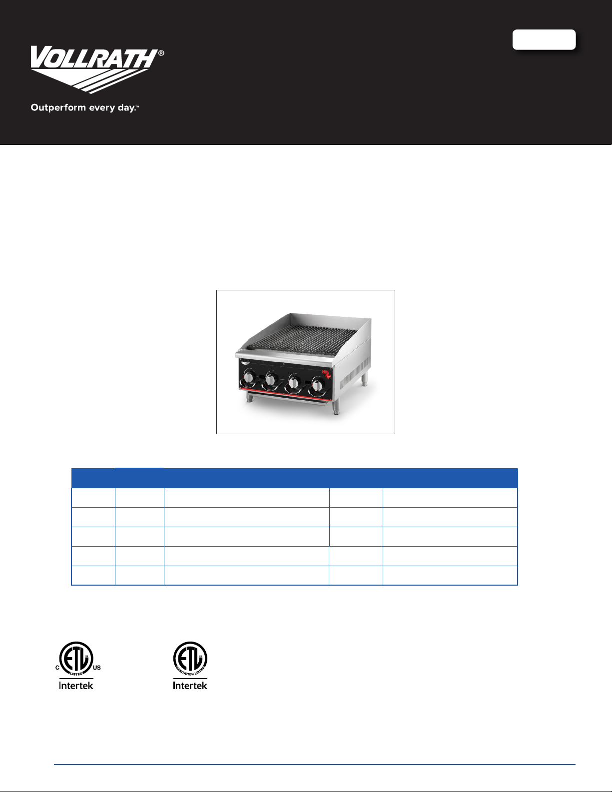
HEAVY DUTY CAYENNE® GAS CHAR BROILER
Item Model Description BTU/hr Gas Type
924CG CBL2024 Gas Char Broiler Radiant/Lava 24” 80,000 Natural Gas or Propane*
936CG CBL2036 Gas Char Broiler Radiant/Lava 36” 120,000 Natural Gas or Propane*
948CG CBL2048 Gas Char Broiler Radiant/Lava 48” 160,000 Natural Gas or Propane*
960CG CBL2060 Gas Char Broiler Radiant/Lava 60” 200,000 Natural Gas or Propane*
972CG CBL2072 Gas Char Broiler Radiant/Lava 72” 240,000 Natural Gas or Propane*
*Shipped setup for Natural Gas and includes a kit for conversion to Propane Gas
Conforms to ANSI
Z83.11b -2009
Certified to CSA
STD 1.8b - 2009
Thank you for purchasing this Vollrath equipment. Before operating the equipment, read and familiarize yourself with the following operating
and safety instructions. SAVE THESE INSTRUCTIONS FOR FUTURE REFERENCE. Save the original box and packaging. Use this
packaging to ship the equipment if repairs are needed.
Conforms to
NSF Std. 4
Item No. 2350069-1 en Rev 06/14
Page 2
Safety PrecautionS
To ensure safe operation, read the following statements and
understand their meaning. Please read carefully.
WARNING
Warning is used to indicate the presence of a hazard that can cause
severe personal injury, death, or substantial property damage if the
warning is ignored.
CAUTION
Caution is used to indicate the presence of a hazard that will or can
cause minor personal injury or property damage if the caution is
ignored.
NOTE
Note is used to notify people of installation, operation, or
maintenance information that is important but not hazard-related.
For Your Safety!
These precautions should be followed at all times. Failure to follow
these precautions could result in injury to yourself and others.
function and PurPoSe
This equipment is intended to be used for grilling foods in commercial
foodservice operations only. It is not intended for household, industrial or
laboratory use.
FOR YOUR SAFETY
Do not store or use gasoline or other ammable vapors
or liquids in the vicinity of this or any other appliance.
WARNING
Improper installation, adjustment, alteration, service
or maintenance can cause property damage, injury
or death. Read the installation, operating and
maintenance instructions thoroughly before installing
or servicing this equipment.
WARNING
FIRE, INJURY or DEATH HAZARD
Have this equipment installed by a qualied installer in
accordance with all federal, state and local codes. Failure to
install this equipment properly can result in injury or death.
WARNING
FIRE, INJURY or DEATH HAZARD
This appliance must be installed and adjusted by a qualied
technician in accordance with all federal, state and local
codes. Failure to install, adjust or maintain this equipment
properly can result in property damage, injury or death.
ENGLISH
unPacking the equiPment
When no longer needed, dispose of all packaging and materials in an
environmentally responsible manner.
1. Remove all packing material and tape, as well as any protective plastic
from the equipment.
2. Use caution and assistance from others in lifting and moving this
equipment.
3. Clean any glue residue left over from the plastic or tape.
4. Place the equipment in the desired position and height.
5. Install the four (4) legs (A) and feet (B) onto the equipment. See Figure 1.
6. Before using this equipment it must be cleaned and dried thoroughly.
initial SetuP
NOTE: It is vital that the purchaser of this equipment post in a prominent
location instructions to be followed in the event that the user smells gas.
This information shall be obtained by consulting the local gas supplier. The
purchaser of this equipment must post in a prominent location
WARNING
Read and understand all instructions and
warnings before using this equipment. Retain this
manual for future reference.
WARNING
FIRE HAZARD
Do not install or use without 4” legs. Use of this equipment
without legs can cause the appliance to overheat and cause
a re.
WARNING
FIRE, INJURY or DEATH HAZARD
This appliance is for use in non-combustible locations only.
WARNING
FIRE and INJURY OR DEATH HAZARD
Injuries or death can occur if this equipment is not used
properly. To reduce risk of injury or death:
Keep the appliance area free and clear from combustibles
Do not obstruct the ow of combustion and ventilation air
Do not spray controls or the outside of the appliance with liquids
or cleaning agents
Let hot appliance cool before cleaning or moving
The appliance should only be used in a at, level position
Do not operate unattended
2
OperatOr’s Manual
Page 3
The installation of this appliance must conform with local codes, or
in the absence of local codes, with the National Fuel Gas Code, ANSI
Z223.1/NFPA 54, or the Natural Gas and Propane Installation Code, CSA
B149.1, as applicable.
The appliance and its individual shutoff valve must be disconnected from
the gas supply piping system during any pressure testing of that system
at test pressures in excess of ½ psi (3.5 kPa).
The appliance must be isolated from the gas supply piping system by
closing its individual manual shutoff valve during any pressure testing
of the gas supply piping system at test pressures equal to or less than
½ psi (3.5 kPa).
Clearance and positioning around the appliance: This appliance
must be installed adjacent to non-combustible surfaces only with a minimum
spacing of 6” from all sides. This appliance must be a minimum distance of
6” from another appliance. The appliance must have the supplied 4” legs
installed and be placed on a non-combustible surface.
Air supply and ventilation: The area in front and around the appliances
must be kept clear to avoid any obstruction of the ow of combustion and
ventilation air. Adequate clearance must be maintained at all times in front of
and at the sides of the appliance for servicing and proper ventilation.
Pressure regulator: All commercial cooking equipment must have
a pressure regulator on the incoming service line for safe and efcient
operation. The regulator provided for this appliance is adaptable for both
Natural gas and LP gas. A conversion kit with separate instructions is
included explaining this procedure in detail.
Regulator information: ¾” NPT inlet and outlet; factory adjusted for 5” WC
Natural Gas standard and may be converted by qualied personnel to be
used for Propane at 10” WC.
Gas piping : Gas piping shall be of such size and so installed as to provide
a supply of gas sufcient to meet the full gas input of the appliance. If the
appliance is to be connected to existing piping, it shall be checked to determine
if it has adequate capacity. Joint compound (pipe dope) shall be used sparingly
and only on the male threads of the pipe joints. Such compounds must be
resistant to the action of LP gases.
Any loose dirt or metal particles, which are allowed to enter the gas lines
on this appliance, will damage the valve and affect its operation. When
installing this appliance, all pipe and ttings must be free from any internal
contaminates. It is recommended that a “drip leg” be installed in-line
before the regulator.
Manual shut off valve: A manual shut off valve should be installed
upstream from the manifold, within 4 ft. (1.2 m) of the appliance and in a
position where it can be reached in the event of an emergency.
Checking for gas leaks: Using a gas leak detector or a soapy water
solution is recommended for locating gas leaks. Matches, candle ame or
other sources of ignition shall not be used for this purpose. Check entire piping
system for leaks.
Exhaust canopy: Cooking appliances inherently create a good deal of heat
and smoke and should be installed under an efcient exhaust hood with ame
proof lters. A vertical distance of not less than 4 ft. (1.2m) shall be provided
between the top of the appliance and lters or any other combustible material.
FIRE DEATH HAZARD
If you smell gas follow the instructions provided by the gas
supplier.
Do not touch any electrical switch; do not try to light the
burner; do not use a telephone within close proximity.
CAUTION
WARNING
ENGLISH
Lighting the pilot: The manifold units are equipped with standing pilots, and
Connection
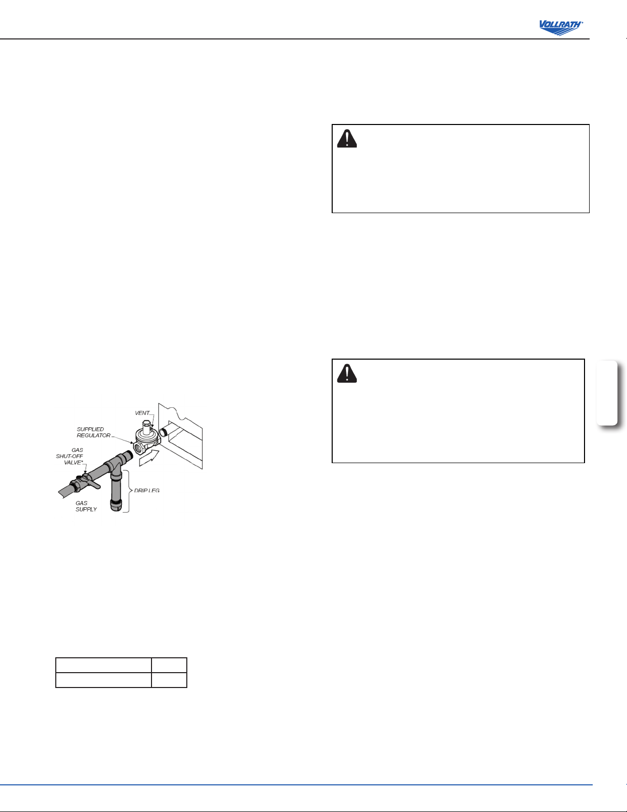
diagram
Prior to connecting the regulator, check the incoming line pressure. The
regulator can only withstand a maximum pressure of ½ PSI (14” WC). If
the line pressure is beyond this limit, a step down regulator before the
regulator provided will be required. The arrow forged into the bottom of the
regulator body shows gas ow direction, and should point downstream to the
appliance.
Gas conversion: Conversion from Natural Gas to Liquid Propane (LP)or
vice versa may only be performed by a qualied technician or service agent.
In the case of troubleshooting, ensure that the correct orice sizes of the
spuds have been provided.
Natural Gas Orice #46
LP Gas Orice #40
NOTE: The orice size is marked on the spud.
Gas connection: The appliance comes tted with a ¾” N.P.T male adapter
for connection to the pressure regulator.
Maintenace: A qualied service company should check the unit for safe and
efcient operation on an annual basis. Contact the factory representative or
local service company to perform maintenance and repairs.
each should be lit immediately after the gas is supplied to the appliance.
1. Before attempting to light pilots, turn off the main gas valve to the appliance
and wait 5 minutes to clear the gas.
2. Turn off all gas control knobs (E). See Figure 1.
3. Turn on control valve and light all pilots.
4. The pilot burner must be lit at the end of the tube. Hold an ignition source
through the pilot light hole (D) in the front panel at the pilot tube. When the
ame is established remove ignition source.
5. To shut down the appliance turn off the main gas valve to the appliance.
NOTE: Smoke appearing on initial use of the appliance is normal. This is as a
result of the rust preventative coating burning off. Allow the appliance to ‘burn
in’ for at least 15 minutes before the rst use.
Pilot ame regulation: The pilot ame on the appliance has been factory
adjusted. When adjustment is necessary, adjust the pilot ames as small as
possible, but high enough to light the burner immediately when burner valve
is turned to the ‘High’ setting. Access to the pilot ame adjustment screw is
obtained by removing the front panel.
Burner adjustment: Remove the front panel to gain access. Turn burner
valve knob to ‘High’ position. Slowly decrease mixing ring aperture to give a
soft blue ame having luminous tips, then slowly increase opening to a point
where the yellow tips disappear and a hard blue ame is obtained.
OperatOr’s Manual
3
Page 4

featureS and controlS
F
G
D
E
G
E
G
D
E
G
C
B
Figure 1. Features and Controls.
A
LEG. Supports the equipment.
B
ADJUSTABLE FEET. Used to adjust the level of the equipment.
C
DRIP TRAY. A tray that collects grease and oil. This tray can be removed
for cleaning. It is recommended that water be in the drip tray to reduce
are-ups and smoking.
ENGLISH
D
PILOT LIGHT ACCESS HOLE. Allows access to the pilot light.
E
GAS CONTROL KNOB. Used to set or adjust the temperature of the
grilling surface.
F
GRILL GRATES. Cooking surface.
G
KNOB GUARD. Helps protect the control knob from damage.
WARNING
FIRE HAZARD
If you smell gas follow the instructions provided by the
gas supplier. Do not touch any electrical switch; do not
try to light the burner; do not use a telephone within close
proximity.
Before initial use, turn the gas control knob to the maximum setting,
and allow equipment to burn-in for 15 minutes. You will notice smoke
appearing due to the cooking surface burning-in. This is normal. After 15
minute burn in period the equipment is ready for use.
To adjust the leveling feet:
1. Hold the leg (A) and rotate the adjustable feet (B) so the equipment is
level. See Figure 1.
2. It is recommended that the grill grates (F) be set at the full tilt position
A
to start. This will allow grease to run down the grill grate(s) (F) and into
the drip tray (C) and will reduce are-ups.
3. Check the drip tray (C) frequently and add water as necessary.
Water vapor rising from the drip tray (C) and through the combustion
chamber will help to reduces are-ups.
4. To ignite the burners, depress and turn the gas control knob (E) to
‘High’ position.
5. Allow the appliance to pre-heat before attempting to use.
6. Adjust the valve set-point to obtain the desired level of heat.
WARNING
FIRE, INJURY or BURN HAZARD
Never attempt to move grates while cooking. Flare-ups
can occur unexpectedly and cause injury. Turn unit off and
allow the grill grate(s) (F) to cool.
7. To adjust the grill grate(s) (F), raise or lower the back of the grates.
Turn unit off and allow the grill grate(s) (F) to cool. Use pot holders or
gloves to reposition.
4
oPeration
WARNING
FIRE, INJURY or DEATH HAZARD
Contact a qualied technician or service agent for any
adjustments, maintenance or repairs. This appliance is not
user serviceable.
WARNING
BURN HAZARD
Hot liquids and steam can burn skin. Never pour any liquid
other than oil to be used for cooking on to hot surfaces.
OperatOr’s Manual
cleaning
To maintain the appearance and increase the service life, clean your
equipment daily.
NOTE:
Do not clean the equipment with steel wool.
1. Allow the equipment to cool completely before cleaning.
2. Using a wire brush, scrape the grill grate(s) (E) to remove any food
residue.
3. Using a damp cloth, sponge dipped in soapy water or metal scraper to
clean the equipment; rinse and dry thoroughly.
4. Dry grates thoroughly to prevent rusting. This may be done by placing
the grates in place and heating the unit as described in the Operation
Section.
5. Empty and clean the drip tray (C). Place the drip tray (C) into the
equipment.
Page 5

converting from lava rock to radiant
converting from radiant to lava rock (hd modelS)
1. Allow the equipment to cool completely before converting.
2. Remove the lava rock (A) and save for future reuse. See Figure 2.
3. Remove the wafe grate(s) (B) and save for future reuse.
4. Remove the lava rock cover(s) (C) and save for future reuse.
5. Place the radiant cover(s) (D) over the burner tubes. See Figure 3.
A
B
C
Figure 2. Lava Rock Components.
1. Allow the equipment to cool completely before converting.
2. Remove the radiant cover(s) (D) and save for future reuse. See Figure 3.
3. Place the lava rock cover(s) (C) over the burner tubes. See Figure 2.
4. Set the wafe grate(s) (B) into place.
5. Set the lava rock (A) onto the wafe grate(s) (B) and spread out evenly.
D
Figure 3. Radiant Components.
ENGLISH
OperatOr’s Manual
5
Page 6

28.7” (729.50 mm)
Item A ” (cm) Burners
28.7” (729.50 mm)
5”
(127 mm)
8.3”
ENGLISH
( 212 mm)
924CG 24” (60.7) 4
936CG 36” (91.5) 6
948CG 48” (122.0) 8
960CG 60” (152.5) 10
972CG 72” (182.9) 12
5”
(127 mm)
8.3”
( 212 mm)
A
6
OperatOr’s Manual
3.3”
( 85 mm)
3.3”
( 85 mm)
Page 7

Service and rePair
There are no user serviceable parts within this appliance. To avoid serious injury or damage, never attempt to repair the Char Broiler yourself. Do not send units
directly to the Vollrath Company. Please contact the qualied professional repair service listed below.
VOLLRATH Technical Service • 1-800-628-0832 • Email: techservicereps@vollrathco.com
When contacting the Authorized Professional Service Center, please be ready with the item number, model number (if applicable), serial number, and proof of
purchase showing the date the unit was purchased.
Warranty Statement for the vollrath co. l.l.c.
This warranty does not apply to products purchased for personal, family or household use, and The Vollrath Company LLC does not offer a written warranty to
purchasers for such uses.
The Vollrath Company LLC warrants the products it manufactures or distributes against defects in materials and workmanship for a period of one year, except as
specically described in our full warranty statement. In all cases, the warranty runs from the date of the end user’s original purchase date found on the receipt.
For complete warranty information, product registration and new product announcement, visit www.vollrath.com.
www.vollrath.com
The Vollrath Company, L.L.C.
1236 North 18th Street
Sheboygan, WI 53081-3201
U.S.A.
Main Tel: 920.457.4851
Fax: 800.752.5620
Technical Services: 800.628.0832
Service Fax: 920.459.5462
Canada Service: 800.695.8560
© 2014 The Vollrath Company, L.L.C.
Item No. 2350069-1 en Rev 06/14
 Loading...