


ENGLISH
Operator’s Manual
CAYENNE® HEAT AND LIGHT STRIPS
Register your product on-line at www.vollrath.com
Thank you for purchasing this Vollrath Food Processing Equipment. Before operating the equipment, read and familiarize yourself with the following operating and safety instructions. SAVE THESE INSTRUCTIONS FOR FUTURE REFERENCE. Save the original box and packaging. Use this packaging to ship the equipment if repairs are needed.
Item No. 17030-1 en Rev 09/14
ENGLISH
Safety Precautions |
|
Do not use extension cords, power strips or surge protectors with this |
||
|
|
unit. |
|
|
To ensure safe operation, read the following statements and understand |
|
Installwithdistancesspecifiedinthe Unit Installation section of this |
||
their meaning. This manual contains safety precautions which are |
|
manual. Minimum distance to the following surfaces. |
||
explained below. Please read carefully. |
|
Combustible surroundings |
5” Sides |
2” Top |
|
Non Combustible surroundings |
1” Sides |
1” Top |
|
|
|
|||
WARNING |
|
Setback from edge of pass-through |
8” from any edge |
|
|
Units that require wiring for installation must follow National Electrical |
|||
Warning is used to indicate the presence of a hazard that can cause |
|
Code (NEC) standards and local ordinances. |
|
|
severe personal injury, death, or substantial property damage if the |
|
Only use coated light bulbs that meet NSF standards and are |
||
warning is ignored. |
|
specificallydesignedforfoodserviceareas.Breakageofbulbsthatare |
||
|
|
not coated could cause injury or contaminate food. |
||
CAUTION |
|
Do not place materials on or allow combustible materials to come in |
||
Caution is used to indicate the presence of a hazard that will or can |
|
contact with unit. |
|
|
|
There are no serviceable parts in this unit. Contact a Vollrath |
|||
cause minor personal injury or property damage if the caution is |
|
Authorized Service Agent for service. |
|
|
ignored. |
|
Authorized service agent must use genuine Vollrath replacement parts. |
||
NOTE |
|
Failure to do so will void warranty and may cause a safety hazard. |
||
|
Do not spray controls or outside of unit with liquids or cleaning agents. |
|||
Note is used to notify people of installation, operation, or maintenance |
|
|||
|
Units that require a circuit breaker larger than 20 amps must have |
|||
information that is important but not hazard-related. |
|
separate circuit for the lighting circuit that is less than 20 amps. |
||
For Your Safety! |
|
Function and Purpose |
|
|
These precautions should be followed at all times. Failure to follow |
|
|
|
|
|
Heat Strips = These units are intended to be used as |
a heat source to help |
||
these precautions could result in injury to yourself and others or damage |
|
|||
|
maintain food at safe temperatures until served. They are not intended |
|||
the equipment. |
|
or designed to cook raw food or to reheat prepared food. Food must be |
||
To reduce risk of injury or damage to the unit: |
|
prepared and placed in food stations at proper temperatures. |
||
|
Light Strips = These units are intended to illuminate food serving display |
|||
Use only grounded electrical outlets or circuits matching the nameplate |
|
|||
|
areas or food preparation areas. |
|
|
|
rated voltage. |
|
|
|
|
|
Unpacking the Equipment and Initial Setup |
|||
Unitshouldonlybeusedinaflat,levelposition. |
|
|||
Turn off unit and let it cool before cleaning or moving. |
|
|
|
|
|
|
|
|
|
Do not operate unattended. |
Carefully remove crating or packaging materials from the unit. Dispose of all |
|
packaging ,materials in an environmentally responsible manner. |
||
|
||
Unit Installation Clearances |
|
|
|
|
 WARNING
Fire Hazard.
Do not install unit near combustible material. Do not place combustible material under or on top of unit. Discoloration or combustion could occur.
 WARNING
Electrical Shock Hazard.
Keep water and other liquids from entering the inside of the unit. Liquid inside the unit could cause an electrical shock. Unit must be installed by qualified personal in accordance with all local and national ordinances. Do not use a power cord that has been modified or damaged.
Thisunitmustbeinstalledbyqualifiedpersonalincompliancewithelectrical codes. The following distances must be kept between the unit and the surrounding surfaces for safe operation. It is recommended that two (2) or more people assist with the installation of this unit.
|
A |
Heat Strip |
C |
|
|
|
B |
Minimum Clearances |
Single |
Single |
Dual |
Dual |
|||||
Non-Combustible |
Combustible |
Non-Combustible |
Combustible |
||||||
|
|
Surface |
Surface |
Surface |
Surface |
||||
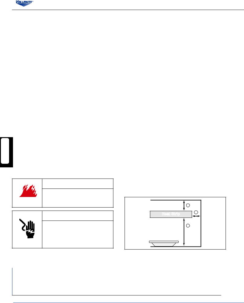
A Top of strip to surface above (minimum) |
1" |
(2.5 cm) |
2" |
(5.1 cm) |
1" |
(2.5 cm) |
2" |
(5.1 cm) |
|
B Bottom of strip to surface |
Medium Wattage |
11" (27.9 cm) |
13" |
(33.0 cm) |
18" |
(45.7 cm) |
20" |
(50.8 cm) |
|
below |
High Wattage |
16" |
(40.6 cm) |
16" |
(40.6 cm) |
24" |
(60.9 cm) |
25" |
(63.5 cm) |
C Side of strip to adjacent surface (minimum) |
1" |
(2.5 cm) |
5" (12.7 cm) |
1" |
(2.5 cm) |
5" (12.7 cm) |
|||
Setback from front opening on pass through application: maximum of 8" (20.3 cm)
2 Operator’s Manual
NOTE:
This unit must be installed in an area that will not be affected by the heat from the unit. Damage to solid surface counter tops or other materials in the heat zone of this product are not covered under warranty.
Kool-Touch® Trim Installation
The Kool-Touch® trim option is shipped separately. It will need to be installed on the unit. We recommend that this option be installed before the unit is mounted.
1.Beginning on the side that does not have the control box (A), slide the Kool-Touch® (B) panel into position by starting at one end of the unit. Slide the Kool-Touch® panel in the channel (C) on the side of the unit until it is in place.(Gangedunitswillrequiretwopiecestrimmedtofit).SeeFigure1.
A |
B |
C
Figure 1. Installation of Kool-Touch® Panels.
2.The side of the unit that has the control box will need to be trimmed. Measure the area that is to be covered by the Kool-Touch® panel.
3.Mark the length to be covered on the Kool-Touch® panel.
4.Place a damp soft cloth under the end of the Kool-Touch® panel to be cut to prevent the Kool-Touch® panel from scratching or slipping while it is being cut.
5.Usingahacksawwithafinemetalorplasticblade,slowlycutthepanelto length.
6.Install the panel on the unit in the same manner as the opposite side.
Unit Installation - Direct Wire Mounting
Top Mount Installation
Top mount brackets may be purchased as an option for direct-wired units. The brackets are available in 1” height or 2” height. Dual units require two sets of brackets.
NOTE:
Top mount brackets may not be used with units longer than 72”.
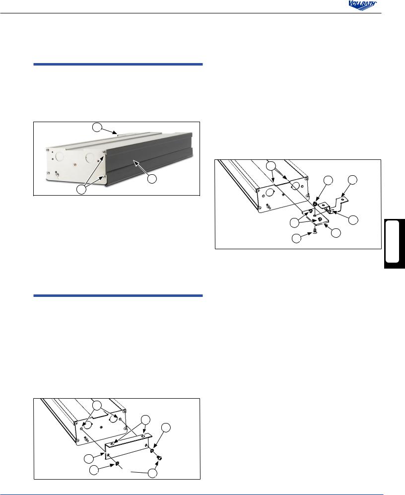
1.Access the area the unit will be mounted in and mark the location the center mount brackets will be mounted. Make sure the material the unit will be mounted to will support the weight of the unit.
2.Secure the top mount bracket (A) to the mounting holes (B) using lockwashers (C) and screws (D). Repeat on the other end. See Figure 2.
B |
E |
C |
A |
C  D
D
Figure 2. Installing Top Mount Brackets.
3.Mount the brackets and unit to a suitable surface using holes (E) and suitable hardware.
Center Mount Installation
Top mount brackets may be purchased as an option for direct-wired units. The brackets are available in 1” height or 2” height. Dual units require brackets on each unit.
NOTE:
For units longer than 72”, a minimum of three (3) mounting points consisting of the two ends and the center of the unit must be used.
1.Access the area the unit will be mounted in and mark the location the center mount brackets will be mounted. Make sure the material the unit will be mounted to will support the weight of the unit.
2.The brackets must be located near the ends of the unit for greatest stability.
3.Mount the hanging bracket (A) with the “T” slot cutout, in the locations identifiedinstep1.Figure3.
D |
B |
E |
F |
A |
G |
C |
Figure 3. Installing Center Mount Brackets.
4.Loosenthetwoscrews(B)locatedinthecenteroftheflatchannel plates (C) far enough so they do not protrude out of the bottom of the plate.
5.Slide the channel plates (C) into the channel (D) on the top of the unit.
6.Measure the distance from the center points of the hanging brackets
(A) and slide the channel plates (C) in the channel (D) on the top of the unit so the center screws (E) in the channel plate (C) match the distance between the center of the “T” slot (G) in the brackets (A).
7.Tighten the two outside screws (B) in the channel plate (C) to lock the channel plate in position.
8.Loosen the nut (F) in the center of the channel plate (C) but DO NOT REMOVE.
9.Raise the unit and align the nut (F) in the center of the channel plate (C) with the “T” in the bracket (A) mounted in step 2.
10.Slide the nut (F) through the “T” slot and TIGHTEN THE NUT to keep the unit in place. THE NUT MUST BE TIGHTENED TO PREVENT THE UNIT FROM SLIPPING OUT OF THE BRACKET.
Chain Mount Installation
NOTE: Units over 72” in length, must use the center mounting point.
1.The unit is shipped with mounting tabs (A) located on each end of the unit. For units that are longer than 72”, three (3) mounting points
consisting of the two ends and the center of the unit must be used. See Figure 4.
2.Loosen the screws (B) holding the mounting tabs in place but do not remove. Rotate tabs (A) to an upright position and the attach chain to holes (C). The chain must support each side of each end of the unit evenly.
ENGLISH
Operator’s Manual 3

3.Hang chain from an appropriate hanging point directly over the area to be kept warm. Make sure the hanging point is adequate for the total weight of the unit and chain.
4.Adjust height of the unit making sure it is level and each point is supporting the weight of the unit evenly.
5.Tighten screws (B) to secure the mounting tabs.
C |
C |
|
A |
||
|
B |
A |
B |
Figure 4. Chain Mount Installation.
Remote Mounting of Control(s)
NOTE: Installations must be in accordance with National Electrical Code (NEC) regulations.
|
|
Control boxes must be mounted securely to surfaces using proper hardware. |
|
|
|
Mount the control box(es) in such a way they will not be bumped or accidently |
|
|
ENGLISH |
||
|
switched on or off. |
||
|
|
|
|
|
|
|
|
|
|
|
|
A |
B |
Figure5.ControlPanelwithSwitchandInfiniteControl.
A |
A |
A |
|
|
Figure 6. Control Panel with Switches
AON/OFF Toggle Switch. Move the toggle switch to the up position for “ON”. Move the toggle switch to the down position for “OFF”. The switch(es) may operate a heating element(s) or light(s).
BINFINITE HEAT CONTROL. Rotate the INFINITE HEAT CONTROL off zero “0” to turn control on. Rotate to desired heat.
Unit Installation - Corded Mounting
On Board Toggle Controls
A
A
Figure 7. On Board Toggle Control with Switches
AON/OFF Toggle Switch. Move the toggle switch to the up position for “ON”. Move the toggle switch to the down position for “OFF”.
Mounting Options
NOTE: UL requires all cord and plug heat strips, from all manufacturers be mounted on legs. All heat strips are custom ordered and therefore cannot be cancelled or returned per Vollrath Terms and Conditions.
Figure 8. Stainless Steel C-Leg Stand - 13” (33 cm)
Figure 9. Stainless Steel T-Leg Stand -
Adjustable 8 to 15” (22.8 to 38.1 cm)
4 Operator’s Manual
 Loading...