

Page 1
Multiva n
www.WestfaliaT4.info - a useful website for owners and enthusiasts of VW Westfalia T4 Transporter / Eurovan Campervans
Caravelle
Transporter
Controls
and
3.1.2
Page 2

CONTENTS
www.WestfaliaT4.info - a useful website for owners and enthusiasts of VW Westfalia T4 Transporter / Eurovan Campervans
AIR CONDITIONING
Heating and ventilation
- Passenger models 2
- Commercial models 10
Air conditioner
- Passenger models 15
- Commercial models 25
Climatronic 32
Auxiliary heater 41
Additional water heater 47
Page 3

CONTROLS
www.WestfaliaT4.info - a useful website for owners and enthusiasts of VW Westfalia T4 Transporter / Eurovan Campervans
AND
EQUIPMENT
Heating and ventilation
(Passenger
You
can
adjust
your vehicle
the heating
achieve this,
heated using the following procedure.
Please note that
perature cannot be any lower
ent temperature.
The best possible heating performance and
quick defrosting of the windscreen can only
be achieved once
its normal operating temperature.
Warning
For road safety it is important
that all windows are free of ice,
snow and mist. Only then can
clear vision be guaranteed.
You should, therefore, familiar-
ise yourself with the correct
operation
tilation system as well as remov-
ing dampness and frost from the
windows.
models)
the
interior temperature
to
suit your requirements using
and
ventilation system.
the
interior
the
of the heating and ven-
is
either cooled
desired interior
the
engine
than
has
the ambi-
reached
of
To
or
tem-
(E)
(D)
Controls
In the instrument panel
(Front seat
A - Rotary regulator - temperature control
B - Rotary switch - blower
C -
Rotary regulator - air distribution
D - Button - air recirculation
E -
Switch over button*
area)
1
B7D-018C]
Controls in rear seat area
F -
Rotary switch - blower
area ventilation*
6 - Rotary regulator - temperature control
for
rear
seat
area heating*
H - Rotary switch - blower
area heating*
The controls in the rear
pillar trim opposite the sliding door and
be operated
On some model versions,
located in the lower area of the pillar trim
next
to the sliding door.
by
the
passengers
seat
the
for
rear
for
rear
area are
in the rear.
controls
seat
seat
in the
can
are
or
CONTROLS
Heating
•
To ensure that the heating and ventilation
can work properly, the air inlet in front of the
windscreen should
snow and leaves.
Rotary regulator A - Temperature
selector
(Front seat
Clockwise - increases heat output
Anti-clockwise - decreases heat output
The rotary switch
your requirements.
The heating effect is dependent
ant temperature -full heating therefore only
possible with the engine
perature.
Rotary switch B - Blower
(Front seat
Air
throughput
stages
with the blower control. When driving slowly the blower should
ning
at a
low speed.
On vehicles with a dust
dust, pollen, soot etc. will
the filter
blower
switch
In
position
switched
air entering the vehicle interior. However
the windows
should only
off.
AND
EQUIPMENT
and
ventilation
be
kept free
area)
can be
area)
can be
regardless
B.
0,
the
air
This
prevents contaminated
will
then mist up the air supply
be
cut
off
adjusted
at
adjusted
and
be
of the
supply and blower are
briefly.
of ice,
to
on
the
operating
in
always
be
pollen filter*
held
back
position
suit
cool-
tem-
four
run-
by
of
as
AIR
2
CONDITIONING
AIR
CONDITIONING
3
Page 4

CONTROLS
www.WestfaliaT4.info - a useful website for owners and enthusiasts of VW Westfalia T4 Transporter / Eurovan Campervans
AND EQUIPMENT
CONTROLS
AND EQUIPMENT
Rotary regulator
tion
(Front seat area)
Reglulator
to
symbol...
W
o
U)
>°
The rotary switch
your requirements.
For vent layout,
Button
D - Air
Air recirculation
button. A warning lamp lights
ton.
After switching
and rear seat areas* operate
culation mode.
Air recirculation
the button again.
goes
out.
The
air
strong outside smells entering
for example when driving through a tunnel
or standing
Air recirculation
vehicle is
air
heated.
For reasons
is
turned
recirculation function prevents
in a
to be
is
drawn
in
not
of
possible
to
the
C - Air
Air vent open... Vents fully
...at windscreen
...at windscreen
in
the
footwell
...to
the
...in
the
can be
see
next page
recirculation
is
selected
on the
is
switched
The
traffic jam.
can
also
heated quickly. In this mode,
from
the
safety,
air
if
rotary regulator
following position:
distribu-
and
upper body 3,
footwell
adjusted
by
blowers
off by
warning lamp then
be
vehicle interior
recirculation
to
7.
pressing this
up
in the
for
the front
in the air
selected
pressing
the
C is
..
recir-
vehicle,
if the
suit
but-
and
Vents slightly open
open
1,
2
1,
2,
5
4
5
Warning
You should
culation mode
period
drawn
windows could mist
Button
The controls
switched open
mode
is
ing
up in
The controls
the button again.
button will switch
seat area heating*
tilation cannot
Note
The buttons D and E can also
combination.
not use the air
of
in
E -
indicated by the warning lamp light-
the
for an
time,
as no
from outside
Switch over button*
in the
by
pressing this button. This
button.
are
switched
The
off.
or
be
operated.
up.
front seat area
off by
warning lamp
In
this mode,
the rear seat area
3,
4
3,
4
1,
2, 3,
4
recir-
extended
fresh
air is
and the
pressing
in the
the
be
pressed
are
rear
ven-
in
Rear
seat area ventilation*
Using
the
passengers
seat area with
circulation mode).
The rear seat area
dently
area,
side
When
cleaned
guided into the rear seat area by vents
roof.
At least
when
blower will otherwise switch
overheating.
To ensure that
can work properly,
windscreen should
snow
Switching
Press
blower switch
Switching
Pres
the blower switch
Rotary switch
Air throughput
stages.
Roof outlets
The roof outlets
separately. They can also
positioning
front seat area ventilation,
in the
rear can ventilate
air
from outside
is
of the
using a blower fitted
trim.
in use, the
the
and
the
the
ventilation
by a
dust
one
vent
blower
the
leaves.
on
switch over button E and turn
F to
off
switch over button E again
the
ventilated indepen-
in the
fresh
air
and
pollen filter*
in
the
roof must
is
functioning
rear seat area ventilation
the air
inlet
be
kept free
blower levels 1
F to
blower level
F -
Blower
can be
outlet grille.
can be
adjusted
closed
be
(not in
front seat
in the
drawn
off due to
in
front
or
adjusted
the
rear right
be
as the
in
the
rear
air
re-
in is
and
in the
open
of
the
of ice,
the
to 3.
or
turn
0.
three
opened
by
re-
•
AIR CONDITIONING
AIR CONDITIONING
5
Page 5

CONTROLS
www.WestfaliaT4.info - a useful website for owners and enthusiasts of VW Westfalia T4 Transporter / Eurovan Campervans
Rear
seat
The rear seat area is heated independently
of the standard vehicle heating in the front
seat area. The air in the rear seat area is
heated via the air recirculation mode.
The rear seat area heating will only function
when the switch over button E has been
pressed and when the blower switch H is in
blower level 1 to 3.
Rotary regulator G - Temperature
selector
Clockwise - increases heat output
Anti-clockwise - decreases heat output
The rotary switch can be adjusted to suit
your requirements.
The heating effect is dependent on the
ant temperature - full heating therefore only
possible with the engine at operating
perature.
Rotary switch H - Blower
Air throughput can be adjusted in three
stages.
Vent in floor
The vent is located on the step between the
front and rear seat areas behind the right
front seat.
Please do not use the area around the vent
as stowage space as the vent opening will
be blocked and the blower in the rear seat
area will turn off due to overheating.
area
AND
EQUIPMENT
heating*
cool tem-
(E) (E)
| B7D-038CJ
B7D-024C
CONTROLS
Air
vents
Depending on the position of the rotary
regulator A heated or unhealed fresh air
flows from vents 1, 2, 4 and 5 in the front
seat area when open.
Only unheated fresh air will flow from vents
3.
On vehicles with a 111 kW engine, heated
fresh air can also flow from vents 3.
The vents are controlled by the rotary regu-
lator C.
The vents 3 and 4 can be opened and closed
separately:
vent opened
side knurled wheel to O
vent closed
side knurled wheel to •
By swinging the complete outlet grille of
vents 3 and 4 the air flow can be moved
vertically.
When the knurled disc in the grille is rotated
to and fro the air flow direction is altered laterally.
The lower area of the windscreen can be
kept demisted via the vents 2.
AND
EQUIPMENT
Warning
Warm air coming from the vent
can damage heat sensitive items.
6
AIR
CONDITIONING
AIR
CONDITIONING
7
Page 6

CONTROLS
www.WestfaliaT4.info - a useful website for owners and enthusiasts of VW Westfalia T4 Transporter / Eurovan Campervans
AND
EQUIPMENT
CONTROLS
AND
EQUIPMENT
(E)
(p)
Defrosting windscreen
windows
We recommend
• Rotary regulator A turned fully
• Rotary switch
• Rotary regulator
• Vents 3 closed
• Adjust vents 4 so that additional warm
can
be
directed
Demisting windscreen
windows
When
the
humidity, e.g. when
mend the following settings:
• Rotary regulator
output.
• Rotary switch
• Rotary regulator
• Vents 3 closed.
• Additional warm
the side windows
the
following settings:
B to
stage
C to
to the
side windows.
windows mist
it is
A at the
B to
stage
C to vr/
air can be
via
vents
up
raining,
| B7D-018C
and
side
to
right.
3.
and
side
due
to
high
we
recom-
desired heat
2 or 3.
directed
4.
Heating interior quickly
We recommend
• Switch
pressing
• Rotary switch B and
• Rotary switch
• Rotary regulator A and
• Switch
button
|
Note information
air operation
• Rotary regulator
•
air
regulator
If the rotary regulator C is in this position
air recirculation
• Vents 3 closed.
air
• Vents
to
the
D.
Warning
You should
culation mode
period
drawn
windows could mist
If
windscreen
4 set as
the
following settings:
on
controls
switch over button
on air
of
time,
in
from outside
C to
in
F* to
recirculation
not use the air
for an
as no
on
on
page
C to ...
is
misted over, rotary<
is
possible.
required.
rear seat area
H* to
stage
G*
up.
recirculating
4. „
E*.
stage
3.
0.
fully
to
right.
by
pressing
recir-
extended
fresh
air is
and the
by
no
Heating interior comfortably
When
the
windows
sired temperature
recommend
• Rotary regulator
output.
• Rotary switch
• Adjust rotary regulator
distribution
•
If
windscreen
regulator
• Switch
button
• Switch
pressing
• Vents 3 closed.
•
Set
the
C to Vl/
off air
D.
off
the
vents
are
clear
and the de-
has
been reached
following settings:
A at the
B to
desired stage.
is
misted over, rotary
recirculation
controls
switch over button
4 as
required.
desired heat
C to
by
in
rear seat area
desired
pressing
E*.
Ventilation (fresh
With the following settings, unhealed fresh
air flows from vents 3 and 4 and
we
• Switch
pressing
• Switch
button
• Rotary switch
air
• Rotary regulator A anti-clockwise
stop
• Rotary switch B and
stage.
• Rotary regulator
•
If
by
regulator
If required, regulator
another position.
• Vents 3 and
General notes
•
In
misting
switch
speeds and
lowing position:
• The stale
in
Therefore when loading
partment ensure that
covered.
on
controls
the
switch over button
off air
D.
^ 0
windscreen
C to
4 in
order
to
prevent
up, you
B to a low
set
the
air
luggage compartment side panels.
air
operation)
in
rear seat area
recirculation
H* to
stage
F* to
C to
is
misted over, rotary<
C can be
roof open.
the
should always
level when driving
rotary regulator
escapes through openings
windows from
the
the
openings
in
roof:
by
E*.
by
pressing
0.
to the
desired
turned
to
set
rotary
at low
C to
the
fol-
9
luggage com-
are not
8
AIR CONDITIONING
AIR CONDITIONING
g
Page 7

CONTROLS
www.WestfaliaT4.info - a useful website for owners and enthusiasts of VW Westfalia T4 Transporter / Eurovan Campervans
AND
EQUIPMENT
CONTROLS
AND
EQUIPMENT
Heating
f
C*rO
i|
You can adjust the interior temperature of
your vehicle to suit your requirements using
the heating and ventilation system. To
I
achieve this, the interior is either cooled or
heated using the following procedure.
Please note that the desired interior tem-
:,
perature cannot be any lower than the ambi-
ent temperature.
The best possible heating performance and
quick defrosting of the windscreen can only
be achieved once the engine has reached
|j
its normal operating temperature.
Warning
For road safety it is important
that all windows are free of ice,
snow and mist. Only then can
clear vision be guaranteed.
You should, therefore, familiar-
ise yourself with the correct
operation of the heating and
tilation system as well as remov-
ing dampness and frost from the
windows.
and
ventilation
in ms o t"ci 01 I
models)
ven-
Controls
A - Rotary regulator - temperature control
for additional heater*
B - Rotary switch - blower for additional
heater*
C - Temperature control rotary regulator
D - Rotary switch - blower
E - Rotary regulator - air distribution
F - Button - air recirculation
B7D-027C
|
Additional heater*
With the additional heater the air in the load
area can be heated. However, there is no
fresh air input as the heat exchanger only
works in recirculating operation.
Rotary regulator A - Temperature
selector
Clockwise - increases heat output
Anti-clockwise - decreases heat output
The rotary switch can be adjusted to suit
your requirements.
The heating effect is dependent on the
ant temperature - full heating therefore only
possible with the engine at operating
perature.
Rotary switch B - blower
Air throughput can be adjusted in three
stages.
Vent
The vent is located on the step between the
front seat area and the load
Please do not use the area around the vent
as stowage space as the vent opening will
be blocked and the blower will turn off due
to overheating.
Warning
Warm air coming from the vent
can damage heat sensitive items.
area.
cool-
tem-
Heating
•
To ensure that the heating and ventilation
can work properly, the air inlet in front of the
windscreen should be kept free of ice,
snow and leaves.
Rotary regulator C - Temperature
selector
Clockwise - increases heat output
Anti-clockwise - decreases heat output
The rotary switch can be adjusted to suit
your requirements.
The heating effect is dependent on the
anttemperature-full heating therefore only
possible with the engine at operating
perature.
Rotary switch D - Blower
Air throughput can be adjusted in four
stages with the blower control. When driving slowly the blower should always be
ning at a low speed.
On vehicles with a dust and pollen filter*
dust, pollen, soot etc. will be held back by
the filter regardless of the position of
blower switch D.
and
ventilation
cool-
tem-
run-
10
AIR CONDITIONING
AIR CONDITIONING
11
Page 8
CONTROLS
www.WestfaliaT4.info - a useful website for owners and enthusiasts of VW Westfalia T4 Transporter / Eurovan Campervans
Rotary
Reglulator
to
symbol...
AND
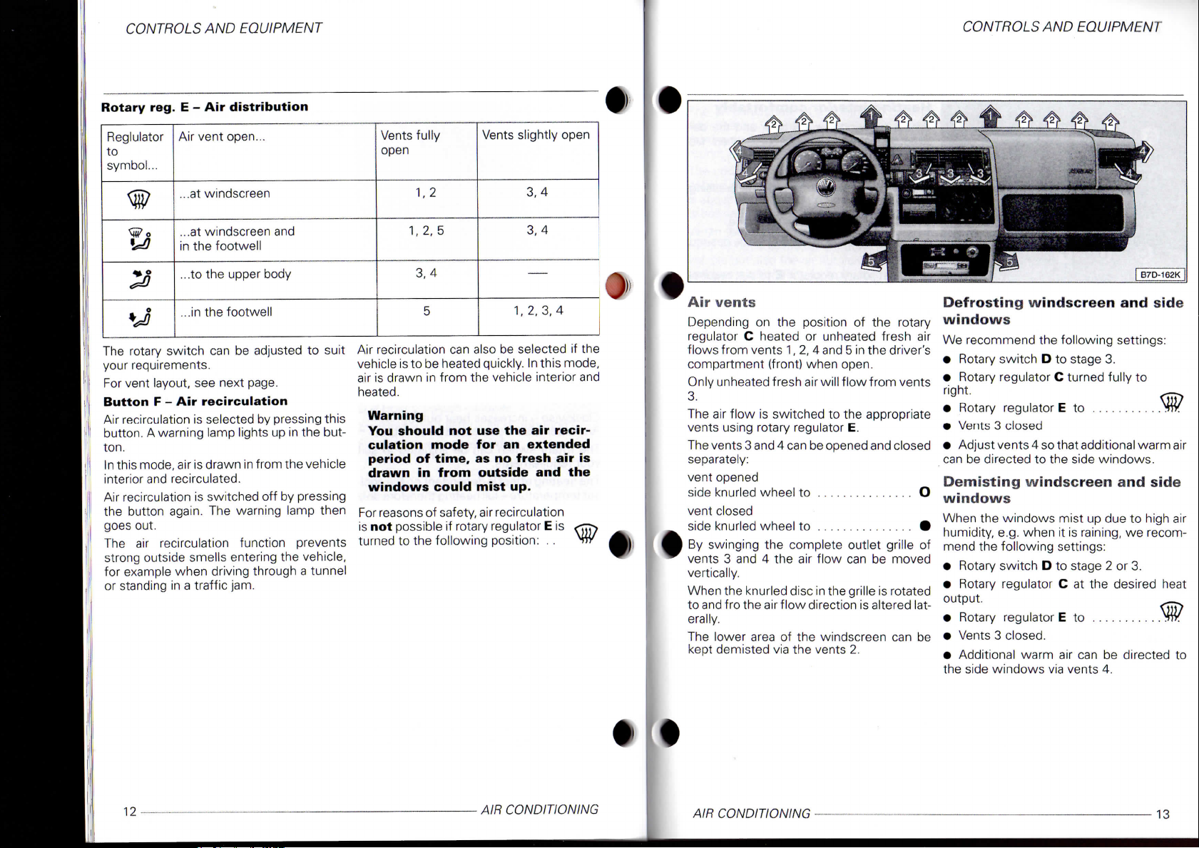
reg. E - Air
Air
...at windscreen 1. 2
EQUIPMENT
distribution
vent open...
9
...at windscreen and
la
•J
The
rotary switch can be adjusted to suit
your requirements.
For
vent layout, see next page.
Button
Air
recirculation is selected by pressing this
button. A warning lamp lights up in the but-
ton.
In this mode, air is drawn in from the vehicle
interior and recirculated.
Air
recirculation is switched off by pressing
the button again. The warning lamp then
goes
out.
The
air recirculation function prevents
strong outside smells entering the vehicle,
for example when driving through a tunnel
or
standing in a traffic jam.
in the footwell
...to the upper body
o
...in the footwell
F - Air
recirculation
Vents
Vents
fully
open
1, 2, 5
3,
4
5
Air
recirculation can also be selected if the
vehicle
is to be heated quickly. In this mode,
air
is drawn in from the vehicle interior and
heated.
Warning
You should not use the air
culation
period
drawn
windows
For
reasons
is
not possible if rotary regulator E is
turned to the following position: .. TTV
mode
of
in
of safety, air recirculation
time,
from
could
for an
as no
slightly open
1, 2, 3, 4
fresh
outside
mist
up.
3,
4
3,
4
—
recir-
extended
air is
and the
CONTROLS
Air
vents
Depending
regulator C heated or unheated fresh air
flows from vents 1, 2, 4 and 5 in the driver's
compartment
Only
3.
The
vents using rotary regulator E.
The
separately:
vent opened
side
vent closed
side
By
swinging the complete outlet grille of
vents 3 and 4 the air flow can be moved
vertically.
When
to and fro the air flow direction is altered laterally.
The
kept demisted via the vents 2.
on the position of the rotary
(front)
when open.
unheated fresh air will flow from vents
air flow is switched to the appropriate
vents 3 and 4 can be opened and closed
knurled wheel to O
knurled wheel to #
the knurled disc in the grille is rotated
lower area of the windscreen can be
Defrosting
windows
We
recommend the following settings:
• Rotary switch D to stage 3.
• Rotary regulator C turned fully to
right.
• Rotary regulator E to Vtr.
• Vents 3 closed
• Adjust vents 4 so
can
be directed to the side windows.
Demisting
windows
When
the windows mist up due to high air
humidity, e.g. when it is raining, we recommend
the following settings:
• Rotary switch D to stage 2 or 3.
• Rotary regulator C at the desired heat
output.
• Rotary regulator E to TT/
• Vents 3
• Additional warm air can be directed to
the side windows via vents 4.
AND
windscreen
that
windscreen
closed.
EQUIPMENT
and side
additional warm air
and side
12
AIR CONDITIONING
AIR CONDITIONING •
13
Page 9
CONTROLS
www.WestfaliaT4.info - a useful website for owners and enthusiasts of VW Westfalia T4 Transporter / Eurovan Campervans
AND
EQUIPMENT
Air
conditioner*
(Passenger
models)
CONTROLS
AND
EQUIPMENT
Heating interior comfortably
When
sired temperature
recommend
•
Switch
button
•
Rotary switch
•
Rotary regulator
heat output.
•
Adjust rotary regulator
*4
O
23
to
right.
no
ments
•
When windscreen misted
rotary regulator
•
Vents 3 closed.
•
Set
Genera! notes
•
The
slots
fore,
On vehicles with a full-width partition
on
stale
driver's
•
In
misting
switch
speeds
lowing
Ventilation
With
the following settings, unheated fresh
air flows from vents
•
Rotary switch
•
Rotary switch
•
Rotary regulator
left.
•
Rotary regulator
•
When windscreen misted
rotary regulator
If
required, regulator
another
•
Vents
Heating interior quickly
•
Rotary switch
•
Rotary regulator
•
Switch
button
Note
information on recirculating
air operation on page 12. „
•
Rotary regulator
•
When windscreen misted
rotary regulator
If
the rotary regulator
air recirculation
•
Vents 3 closed.
•
Vents
(fresh
position.
3 and 4
on air
F.
4 set as
air
operation)
3 and 4:
B to
stage
0.
D to
desired stage.
A* and C
E to
E to
E can be
open.
B* and D to
A* and C
recirculation
E to
E to w
E is
is
possible.
required.
fully
to the
up set
turned
stage
3.
fully
to
by
pressing
up set
in this position
the
windows
the
following settings:
off air
F.
for air
vents
stale
in the
these slots should
the
Pick-up and Double
air
and
order
up, you
D to a low
and
position:
recirculation
B to
distribution
E to
4 as
required.
air
escapes
load area side panel
escapes
front
passenger
to
prevent
should
set
rotary regulator
are
clear
has
desired stage.
A*
through slots
level when driving
and the de-
been reached
by
pressing
and
C at
the desired
E to
suit require-
up set <^ry
through ventilation
trim.
not be
the
covered.
Cab
models
doors.
windows from
always
set
E to
we
There-
and
the
in the
rotary
at low
the
fol-
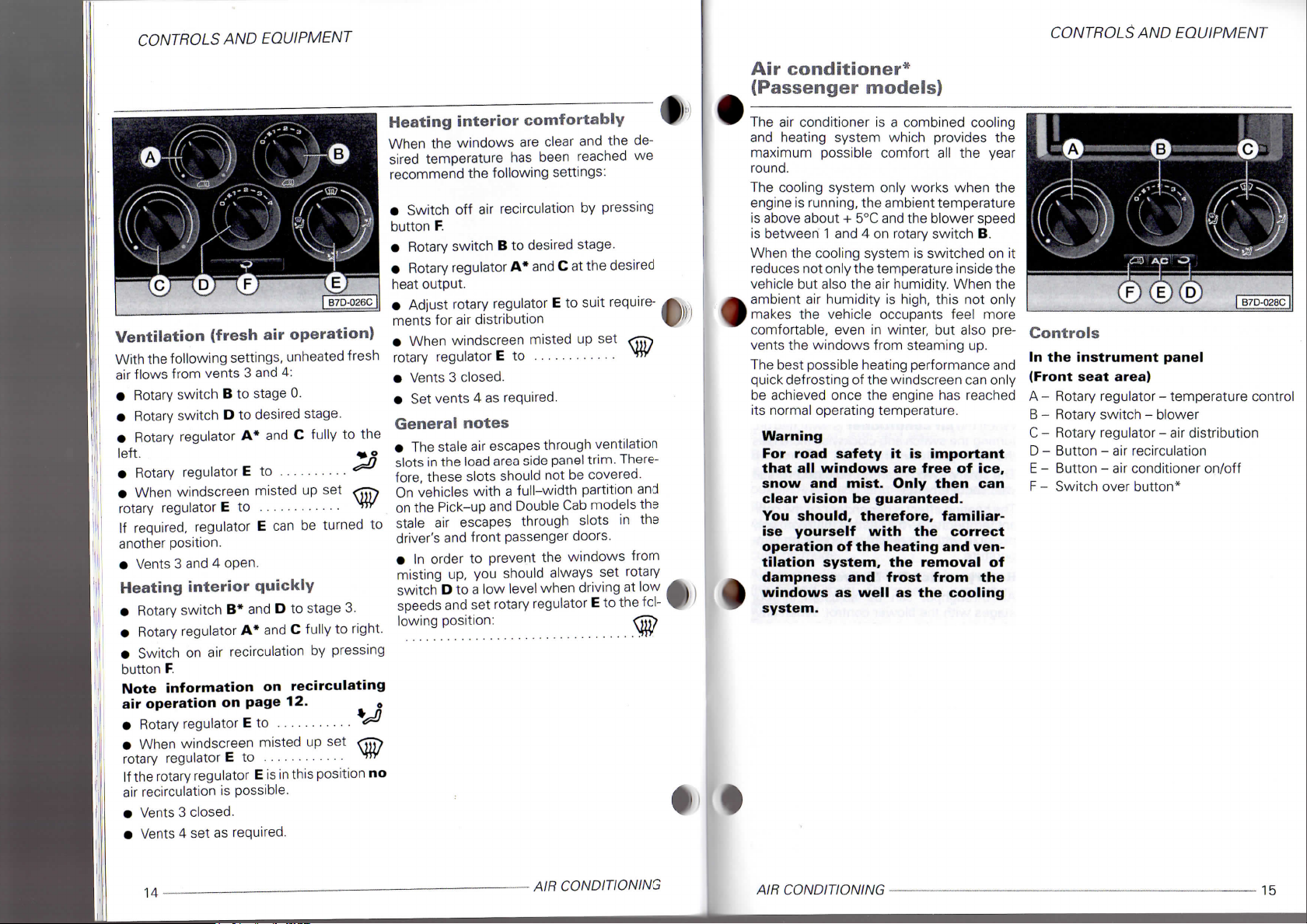
The
air
conditioner
and heating system which provides
maximum possible comfort
round.
The cooling system only works when
engine
is
is above about + 5°C and
is between 1
When
reduces not only the temperature inside
vehicle
ambient
makes
comfortable,
vents
The best possible heating performance
quick defrosting
be achieved once
its normal operating temperature.
running, the ambient temperature
the
cooling system
but
also
air
the
vehicle occupants feel more
the
windows from steaming
Warning
For road safety it is important
that all windows are free of ice,
snow and mist. Only then can
clear vision be guaranteed.
You should, therefore, familiarise yourself with the correct
operation of the heating and ventilation system, the removal of
dampness and frost from the
windows as well as the cooling
system.
and 4 on
the air
humidity
even
in
of
the windscreen
the
is a
combined cooling
all the
the
blower speed
rotary switch
is
switched
humidity. When
is
high, this
winter,
but
engine
has
B.
not
also pre-
up.
can
reached
the
year
the
on it
the
the
only
and
only
(F)
(E) (D)
Controls
In the instrument panel
(Front
seat
area)
A - Rotary regulator - temperature control
B - Rotary switch - blower
C -
Rotary regulator
D - Button
E -
Button
F -
Switch over
- air
- air
- air
distribution
recirculation
conditioner on/off
button*
I
B7D-028C
|
AIR
14
-
CONDITIONING
AIR
CONDITIONING
15
Page 10

CONTROLS
www.WestfaliaT4.info - a useful website for owners and enthusiasts of VW Westfalia T4 Transporter / Eurovan Campervans
AND
EQUIPMENT
CONTROLS
AND EQUIPMLNI
Controls in
G
- Rotary switch - blower for rear seat
area
H
- Rotary regulator - temperature control
for rear seat area heating*
I - Rotary switch - blower for rear seat
area
The
controls in the rear seat area are in the
pillar
trim
be
operated by the passengers in the rear.
On
some model versions, the controls are
located in the lower area of the pillar
next to the sliding door.
rear
seat
area
ventilation*
heating*
opposite the sliding door and can
trim
or
Air
conditioner
Rotary
regulator
selector
Clockwise
Anti-clockwise
When
turning the switch anti-clockwise increases
the cooling.
The
your requirements.
The
ant temperature-full heating therefore only
possible
perature.
Rotary
Air
stages
ing slowly the blower should always be run-
ning at a low
On
dust, pollen, soot etc. will be held back by
the
blower switch B.
In position 0, the blower and air conditioner
are switched off. To prevent contaminated
air (smells) entering the vehicle interior,
press
- increases heat output
the air
rotary switch can be adjusted to suit
heating effect is dependent on the
with
switch
throughput can be adjusted in four
with
vehicles
filter
regardless of the position of
button D (air recirculation).
A -
Temperature
- decreases heat output
conditioner
the engine at operating tem-
B -
the blower control. When driv-
speed.
with
a dust and pollen
is switched on,
cool-
Blower
filter*
Rotary
tion
The
your requirements.
For
Button
Air
button. A warning lamp lights up in the but-
ton.
After switching on the blowers for the
and
culation mode.
Air
I the button again. The warning lamp then
goes
The
strong outside smells entering the vehicle,
for example when driving through a tunnel
or standing in a traffic jam.
Air
vehicle
this mode, air is drawn in from the vehicle
interior and heated or cooled.
regulator
Reglulator
to
symbol...
>°
•J
rotary switch can be adjusted to suit
vent layout, see next page 21.
D - Air
recirculation is selected by pressing this
rear seat
recirculation is switched off by pressing
out.
air recirculation function prevents
recirculation can also be selected if the
is to be heated or cooled quickly. In
C
Air distribu-
Air
vent open...
...at windscreen
...at windscreen and
in the footwell
...to the upper body
...in the footwell
recirculation
areas*
operate in the air recir-
front
Vents
fully
open
1, 2
1, 2, 5
3,
4
5
Warning
You should not use the air
culation
period
drawn
mist
Smoking
culation is selected, as the smoke drawn in
from the vehicle interior deposits on the
evaporator of the air conditioner. This leads
to permanent odours when the air conditioner is in operation. These can only be
eliminated by exchanging the evaporator,
which is time-consuming and expensive.
Note
Buttons D, E and F can be used in combination.
mode
of
time,
in and the
up.
should be avoided when air recir-
Vents
for an
as no
fresh
windows
slightly open
3,
4
3,
4
1, 2, 3, 4
recir-
extended
air is
could
For
reasons of safety, air recirculation
is
not possible if rotary regulator C is
turned to the following position: ..
16
AIR CONDITIONING
AIR CONDITIONING
9
17
Page 11

CONTROLS
www.WestfaliaT4.info - a useful website for owners and enthusiasts of VW Westfalia T4 Transporter / Eurovan Campervans
AND
EQUIPMENT
CONTROLS
AND
EQUIPMENT
Button E - Air conditioner on/off
The system is switched on by pressing this
button.
A warning lamp lights up in the but-
ton pressed.
The system is switched off by pressing the
button again. The warning lamp then goes
out.
Note
Buttons D, E and F can be used in combina-
tion.
Button F - Switch over button*
The controls in the front seat area are
switched open by pressing this button. This
mode is indicated by the warning lamp lighting up in the button.
The controls are switched off by pressing
the button again. The warning lamp in the
button will switch off. In this mode, the rear
seat area heating* or the rear seat area
tilation cannot be operated.
Note
Buttons D, E and F can be used in combina-
tion.
ven-
Rear seat area ventilation*
Using the front seat area ventilation, the
passengers in the rear can ventilate the rear
seat area with air from outside (not in air re-
circulation mode).
The rear seat area is ventilated indepen-
dently of the ventilation in the front seat
area,
side
trim.
When in use, the fresh air drawn in is
cleaned by a dust and pollen filter* and
guided into the rear seat area by vents in the
roof.
At least one vent in the roof must be open
when the blower is functioning as the
blower will otherwise switch off due to
overheating.
To ensure that the rear seat area ventilation
can work properly, the air inlet in front of the
windscreen should be kept free of ice,
snow and leaves.
Switching on
Press switch over button F and turn the ro-
tary switch G to blower stages 1 to 3.
Switching off
Press switch over button F again or turn the
rotary switch G to blower stage 0.
• 0
Rotary switch G - Blower
Air throughput can be adjusted in three
stages.
Roof outlets
The roof outlets can be closed or opened
separately. They can also be adjusted by repositioning the outlet grille.
using a blower fitted in the rear right
(F)
[ B7D-030C
J
18 -
AIR CONDITIONING
AIR CONDITIONING -
19
Page 12

CONTROLS
www.WestfaliaT4.info - a useful website for owners and enthusiasts of VW Westfalia T4 Transporter / Eurovan Campervans
Rear seat area heating*
The rear seat area is heated independently,
of the standard vehicle heating in the front
seat area. The air in-the rear seat area is
heated via the air recirculation mode.
The rear seat area will only function when
switch over button F is pressed and when
the the blower switch I is set to blower
stages 1 to 3.
Rotary regulator H - Temperature
selector
Clockwise - increases heat output
Anti-clockwise - decreases heat output
The rotary switch can be adjusted to suit
your requirements.
The heating effect is dependent on the
ant temperature-full heating therefore only
possible with the engine at operating
perature.
Rotary switch I - Blower
Air throughput can be adjusted in three
stages.
Vent in floor
The vent is located on the step between the
front and rear seat areas behind the right
front seat.
Please do not use the area around the vent
as stowage space as the vent opening will
be blocked and the blower in the rear seat
area will turn off due to overheating.
Warning
Warm air coming from the vent
can damage heat sensitive items.
AND
EQUIPMENT
cool-
tem-
fp)
I B7D-030C |
B7D-032C
CONTROLS
Air vents (front)
Depending on the position of rotary regulator A and button E, heated or unheated
fresh air/cold air flows from all vents which
are open.
The outlets are controlled by the rotary
regulator C.
The vents 3 and 4 can be opened and closed
separately:
vent opened
side knurled wheel to O
vent closed
side knurled wheel to #
By swinging the complete outlet grille of
vents 3 and 4 the air flow can be moved
vertically.
When the knurled disc in the grille is rotated
to and fro the air flow direction is altered laterally.
The lower area of the windscreen can be
kept demisted via the vents 2.
Defrosting windscreen and side
windows
We recommend the following settings:
• Rotary regulator A turned fully to right.
• Rotary switch B to stage 3.
• Rotary regulator C to
• Vents 3 closed
• Adjust vents 4 so that additional warm air
can be directed to the side windows.
Demisting windscreen and side
windows
When the windows mist up due to high air
humidity, e.g. when it is raining, we recommend the following settings:
• Switch on air conditioner by pressing button E
• Rotary switch B to stage 2 or 3.
• Rotary regulator A at the desired heat
output.
• Rotary regulator C to
• Vents 3 closed.
• Additional warm air can be directed to
the side windows via vents 4.
AND
EQUIPMENT
20
AIR CONDITIONING
AIR CONDITIONING
21
Page 13

CONTROLS
www.WestfaliaT4.info - a useful website for owners and enthusiasts of VW Westfalia T4 Transporter / Eurovan Campervans
Ventilation
With
the following settings, unheated fresh
air flows from vents 3 and 4 and
•
Turn
air
ton
E.
•
Switch
button
•
Switch
pressing the switch over button
•
Rotary switches
stage.
•
Rotary switch
•
Rotary regulator A anti-clockwise to
stop
•
Rotary regulator C to
•
If
regulator
If
required, regulator
another
•
Vents 3 and 4 in roof
off air
D.
on
windscreen
C to
position.
AND
(fresh
conditioner
recirculation
controls
B and G* to
I* to
is
misted over,
EQUIPMENT
air operation)
in
off by
pressing but-
by
pressing
in
rear
seat
F*.
stage
0.
^
rotarySJTJTJ
C can be
open.
turned
roof:
area
by
desired
the
to
3.
•
by
f
#
Heating
•
Switch
pressing the switch over button
•
Rotary switches B and
•
Rotary switch
•
Rotary regulators A and
•
Switch
button
Warning
You should not use the air recirculation mode for an extended
period
drawn in from outside.
Note
air operation on page 17. 0
•
Rotary regulator
•
If
regulator
•
Vents 3 closed.
•
Vents 4 and
interior
on
on air
D.
of time as no fresh air is
information on recirculating
windscreen
C to
controls
G* to
recirculation
C to
is
misted over,
in
roof
quickly
in
rear
seat
I* to
stage
3.
H*
fully to right.
by
set as
required.
area
F*.
stage
pressing
rotary<
#
Heating
When
sired temperature
recommend the following settings:
•
pressing the switch over button
•
button
•
stage.
•
sired heat output.
•
tribution
•
regulator
•
Normal cooling
•
pressing the switch over button
•
ton
•
•
perature (heating
•
When rotary regulator
position,
dash panel must
cooling system
up.
•
interior
the
windows
Switch
Switch
Rotary switches
Rotary regulators
Set
If
Vents 3 and 4 and in roof set
Switch
Switch
Rotary switch B to desired stage.
Rotary regulator A to
Rotary regulator C to desired
Vents 3 and
on
off air
D.
rotary regulator C to required air dis-
setting
windscreen
C to
off
on
E
air conditioner by pressing but-
at
least
comfortably
are
clear
has
been reached
controls
controls
4 set as
in
rear
recirculation
B and I* to
A and H* at the de-
is
misted over,
in
rear
the desired air
is
also possible).
C is in
one
vent
in the ^
be
open,
as the
will
otherwise
required.
and the de-
seat
area
F*.
by
pressing
desired
rotary^TTTN
as
required.
seat
area
F*.
position.
this
ice
we
by
by
tem-
*5
CONTROLS
Maximum
•
All
windows
closed.
•
Switch on air conditioner by pressing but-
ton
E
•
Rotary switch B and G* to desired stage.
•
Rotary switch
•
Rotary regulator A anti-clockwise to the
st°P
*o
•
Rotary regulator C to
•
If
windscreen
regulator
If
air recirculation
•
Vents 3 and 4 in roof
At least one vent
ment panel must always be open otherwise
the
•
Switch
button
Note
air operation on page 17.
C to M4v
the
rotary regulator
A/C
system
on air
D.
Warning
You should not use the air recir-
culation mode for an extended
period
drawn in from outside.
of time as no fresh air is
information on recirculating
AND
EQUIPMENT
cooling
and
sliding/tilting roof*
I* to
stage
0.
...
is
misted over, rotary
C is
in
is
possible.
in
the roof and in the instru-
will
recirculation
this position
open.
ice up.
by
no
pressing
AIR
22
CONDITIONING
AIR
CONDITIONING
23
Page 14

CONTROLS
www.WestfaliaT4.info - a useful website for owners and enthusiasts of VW Westfalia T4 Transporter / Eurovan Campervans
Using
air
AND
EQUIPMENT
conditioner
economically
In cooling operation the air conditioner compressor places demands on the engine and
therefore influences the fuel consumption.
To keep the period switched
possible,
noted:
•
If the
after
is recommended
briefly
•
The air
switched on during a journey
or sliding/tilting roof* are open.
•
If
attained without switching on the
tioner, the fresh
lected.
General
• When
and
can drip
puddle under
mal and does
•
If the air
for some time, a build-up
in
vent the odours, turn
at full blast
temperature
for a short period whilst doing this.
the
following points should
inside temperature
the car
the desired interior temperature can
has been parked
to
to
enable
conditioner should
open doors or windows
the hot air to
air
operation should
notes
the
the air
the
ambient temperature
very humid, condensed water
off the
vaporiser
evaporator
the
vehicle. This
not
indicate a leak.
conditioner
can
at
least once a month when
is
above
on as
is
very high
in the
escape.
not be
if
the windows
air
and
is
quite nor-
has not
of
cause odours.
on the air
5°
C. Open a window
been used
natural deposits
conditioner
short
sun,
condi-
be se-
is
high
form
To
as
be
it
be
a
pre-
the
•
To
ensure that
and
air
conditioner* can work properly,
air inlet in front
kept free
•
The
in
Therefore when loading
partment ensure that the openings
covered.
of
stale
the
luggage compartment side panels.
the
heating, ventilation
of
the windscreen should
ice, snow and leaves.
air
escapes through openings
the
luggage com-
the
be
are not
Operating faults
•
If
the cooling output drops off, switch the
A/C
off
and have
• Should the air conditioner not work at any
time,
either:
-
the
ambient temperature
+5°C,
- the fuse has blown.
Check fuse and,
the trouble
switch
the
-
the
compressor
has switched
coolant temperature being
the
system checked.
if
is not due to a
system
necessary, renew
off
and have
of the
off
temporarily
f;
is
below about
defective fuse,
cooling system
too
it. If
it
checked.
due to the
high.
gk
•
Air conditioner*
(Commercial models)
The
and heating system which provides
maximum possible comfort
round.
The cooling system only works when
engine
is above about + 5°C and the blower speed
is between 1 and
When
reduces not only the temperature inside the
vehicle
ambient
makes
comfortable, even
vents
The best possible heating performance and
quick defrosting
be achieved once
its normal operating temperature.
Warning
For road safety
that
snow
clear vision
You should, therefore, familiarise yourself with
operation
tilation system,
dampness
•
windows
system.
air
conditioner
is
running, the ambient temperature
the
cooling system
but
also
air
the
vehicle occupants feel more
the
windows from steaming
all
windows
and
is a
combined cooling
all the
4 on
rotary switch
is
switched
the air
humidity
humidity. When
is
high, this
in
winter,
but
of
the windscreen can only
the
engine
has
it is
important
are
free
mist. Only then
be
guaranteed.
the
of
the heating and ven-
the
and
as
well
removal
frost from
as the
correct
tho
year
the
D.
on it
the
not
only
also pre-
up.
reached
of ice,
can
of
the
cooling
CONTROLS
AND
EQUIPMENI
Controls
A - Rotary regulator - temperature control
for additional heater*
B - Rotary switch - blower
heater*
C - Temperature control rotary regulator
D - Rotary switch - blower
E - Rotary regulator
F- Button
G - Button
- air
- air
- air
recirculation
conditioner on/off
for
additional
distribution
24
AIR CONDITIONING
AIR CONDITIONING
25
Page 15

CONTROLS
www.WestfaliaT4.info - a useful website for owners and enthusiasts of VW Westfalia T4 Transporter / Eurovan Campervans
AND
EQUIPMENT
j B7D-034C
Additional heater*
With the additional heater, the air in the load
area
can be
fresh
works
Rotary regulator
selector
Clockwise - increases heat output
Anti-clockwise - decreases heat output
The rotary switch
your requirements.
The heating effect is dependent on the
ant temperature-full heating therefore only
possible with
perature.
Rotary switch
Air throughput
stages.
Vent
The vent
front seat and load areas.
Please
as stowage space
be blocked and
to overheating.
Warning
Warm
can damage heat sensitive items.
heated. However, there
air
input
in
as the
recirculating operation.
the
is
located on the step between
do not use the
air
coming from
heat exchanger only
A -
Temperature
can be
engine
B -
blower
can be
the
adjusted
area around
as the
blower will turn
is no
adjusted
at
vent opening will
to
operating
in
the
off
the
vent
suit
cool-
tem-
three
the
vent
due
Air conditioner
•
To
ensure that
and air conditioner can work properly, the air
inlet
in
front
kept free
Rotary regulator
selector
Clockwise - increases heat output
Anti-clockwise - decreases heat output
When the
turning the switch anti-clockwise increases
the cooling.
The rotary switch
your requirements.
The heating effect is dependent on the
ant temperature-full heating therefore only
possible with
perature.
Rotary switch
Air throughput
stages with
ing slowly the blower should always
ning
On vehicles with a dust
dust, pollen, soot etc. will
the filter regardless
blower switch
In position
are switched
air (smells) entering
press button
of
air
at a low
the
heating, ventilation
of the
ice, snow and leaves.
the
0, the
windscreen should
C -
Temperature
conditioner
can be
the
engine
D -
can be
blower control. When driv-
speed.
D.
blower and
off. To
F (air
recirculation).
is
switched on,
adjusted
at
operating
Blower
adjusted
and
pollen filter*
be
of the
prevent contaminated
the
held back
air
vehicle interior,
to
suit
cool-
tem-
in
four
be
position
conditioner
be
run-
by
of
Rotary
reg. E - Air
Reglulator
to
symbol...
*9
>°
The rotary switch
your requirements.
For vent layout,
Button
Air recirculation
button. A warning lamp lights
ton.
Air recirculation
the button again.
goes
out.
The
air
strong outside smells entering
for example when driving through a tunnel
or standing
Air recirculation
vehicle
is to be
this mode,
interior and heated
For reasons
is
not
possible
turned
to the
Air vent open...
...at windscreen
a
...at windscreen
in
...to
...in
F - Air
recirculation function prevents
in a
air is
of
safety, air recirculation
if
following position:
distribution
the
footwell
the
upper body
the
footwell
can be
see
recirculation
is
selected
is
switched
The
traffic jam.
can
heated
drawn
or
rotary regulator
adjusted
next page.
by
off by
warning lamp then
also
be
selected
or
cooled quickly.
in
from
cooled.
and
to
suit
pressing this
up in the
the
the
but-
pressing
vehicle,
if the
In
vehicle
E is
. .
CONTROLS
Vents fully
open
Warning
You should
culation mode
period
drawn
mist
up.
Smoking should
culation
is
from
the
evaporator
to permanent odours when
tioner
is in
eliminated
which
is
Button
The system
button. A warning lamp lights
ton pressed.
The system
button again.
out.
G - Air
AND
1.
2
1,
2, 5
3,
4
5
not use the air
of
time,
in and the
selected,
vehicle interior deposits
of
the
operation. These
by
exchanging
time-consuming and expensive.
is
switched
is
switched
The
EQUIPMENT
Vents slightly open
for an
as no
windows could
be
avoided when
as the
air
conditioner. This leads
the
conditioner on/off
on by
off by
warning lamp then goes
3,
4
3,
4
1,
2, 3, 4
recir-
extended
fresh
air is
air
smoke drawn
the air
can
pressing this
up in the
pressing
recir-
on the
condi-
only
evaporator,
but-
in
be
the
26
AIR CONDITIONING
AIR CONDITIONING
27
Page 16

CONTROLS AND EQUIPMENT
www.WestfaliaT4.info - a useful website for owners and enthusiasts of VW Westfalia T4 Transporter / Eurovan Campervans
CONTROLS AND EQUIPMENT
Air vents
Depending on the position of rotary regula-
tor C and button G heated or unheated
fresh air/cold air flows from all vents which
are open.
Only unheated fresh air will flow from vents
3.
The vents are controlled by the rotary regu-
lator E.
The vents 3 and 4 can be opened and closed
separately:
vent opened
side knurled wheel to O
vent closed
side knurled wheel to •
By swinging the complete outlet grille of
vents 3 and 4 the air flow can be moved
vertically.
When the knurled disc in the grille is rotated
to and fro the air flow direction is altered lat-
erally.
The lower area of the windscreen can be
kept demisted via the vents 2.
Defrosting windscreen and side
windows
We recommend the following settings:
• Rotary switch D to stage 3.
• Rotary regulator C turned fully to
right.
• Rotary regulator E to
• Vents 3 closed
• Adjust vents 4 so that additional warm air
can be directed to the side windows.
Demisting windscreen and side
windows
When the windows mist up due to high air
humidity, e.g. when it is raining, we recommend the following settings: A
• Switch on air conditioner by pressing button G
• Rotary switch D to stage 2 or 3.
• Rotary regulator C, if necessary, into
heating range.
• Rotary regulator E to w<
• Vents 3 closed.
• Additional warm air can be directed to
the side windows via vents 4.
Ventilation (fresh
With the following settings, unheated fresh
air flows from vents 3 and 4:
• Rotary switch B* to stage 0.
• Rotary switch D to desired stage.
• Rotary regulators A* and C anti-clockwise to the stop ^ „
• Rotary regulator E to ^
• When windscreen misted up set <^rj
rotary regulator E to ^"V
If required, regulator E can be turned to
another position.
• Vents 3 and 4 open.
Heating interior quickly
• Rotary switches B* and D to stage 3.
• Rotary regulators A* and C fully to right.
• Switch on air recirculation by pressing
button F.
Warning
You should not use the air recir-
culation mode for an extended
period,
and the windows could mist up if
the air conditioning is off.
Note information on recirculating
air operation on page 27. „
• Rotary regulator E to . . . *J
• When windscreen misted up set ^jj:^
rotary regulator E to vr/
If the rotary regulator E is in this position no
air recirculation is possible.
• Vents 3 closed.
• Vents 4 set as required.
as no fresh air is drawn in
air
operation)
Heating interior comfortably
When the windows are clear and the desired temperature has been reached we
recommend the following settings:
• Switch off air recirculation by pressing
button F.
• Rotary switches B* and D to desired
stage.
• Rotary regulators A* and C at the desired heat output.
• Adjust rotary regulator E to suit required
air distribution
• When windscreen misted up set sr^y
rotary regulator E to Miy
• Vents 3 closed.
• Set vents 4 as required.
28
AIR CONDITIONING
AIR CONDITIONING
29
Page 17

CONTROLS
www.WestfaliaT4.info - a useful website for owners and enthusiasts of VW Westfalia T4 Transporter / Eurovan Campervans
AND
EQUIPMENT
CONTROLS
AND EQUIPMI Nl
Norma!
• Switch on air conditioner by pressing
ton G
• Switch off air recirculation by pressing
button
• Rotary switch B* to stage 0.
• Rotary switch D to desired stage.
• Rotary regulator C to the desired air tem-
perature (heating is also possible).
• Rotary regulator E to desired position.
When rotary regulator E is in this +
position , at least one vent in the
dash
cooling system will otherwise ice
up.
• Vents 3 and 4 set as required.
cooling
but-
F.
2
panel must be open, as the
Maximum
• All windows and sliding/tilting
closed.
• Switch on air conditioner by pressing
ton G
• Rotary switch D to highest stage.
• Rotary switch B* to stage 0.
• Rotary regulator A anti-clockwise to the
stop ^ o
• Rotary regulator E to ~
• When windscreen misted up set \" )
rotary regulator E to
If the rotary regulator E is in this position no
air recirculation is possible.
• Vents 3 and 4 open.
At least one vent in the instrument panel
must always be open otherwise the A/C
system will ice up.
• Switch on air recirculation by pressing
button
Warning
You should not use the air
culation
period, as no
and the
the air
Note
air
operation
cooling
F.
mode
fresh
windows
conditioning
information
on
page
for an
air is
could
is off.
on
recirculating
27.
roof*
but-
recir-
extended
drawn
mist
in
up if
' '
Using air
economically
In cooling operation the air conditioner
pressor
places demands on the engine and
therefore influences the fuel consumption.
To
keep the period switched on as short as
possible,
noted:
• If the inside temperature is very high
after the car has been parked in the sun, it
is
recommended to open doors or windows
briefly to enable the hot air to
• The air conditioner should not be
switched on during a journey if the windows
or sliding/tilting
• If the desired interior temperature can be
attained
tioner, the fresh air operation should be se-
• When the ambient temperature is high
and the air very humid, condensed water
• If the air conditioner has not been used
for some time, a build-up of natural deposits
vent the odours,
at
temperature is above 5° C. Open a window
for a short period whilst doing this.
without
lected.
General
can
drip off the evaporator and form a
puddle under the vehicle. This is quite normal and does not indicate a leak.
in the vaporiser can cause odours. To pre-
full
blast at least once a month when the
conditioner
com-
the following points should be
escape.
roof*
are open.
switching on the air condi-
notes
turn
on the air conditioner
• The stale air
slots in the load area side panel trim. These
slots should not, therefore, be covered.
On
vehicles
on the Pick-up and Double Cab models the
stale air
driver's and passenger doors.
Operating
• If the cooling
A/C
off and have the system
• Should the air conditioner not work at any
time, either:
- the ambient temperature is below about
+5°C,
- the fuse has blown.
Check
fuse and, if necessary, renew it. If
the trouble is not due to a defective fuse,
switch the system off and have it
- the compressor of the cooling system
has
switched off temporarily due to the
coolant temperature being too high.
escapes
with a full-width
escapes
through slots in the
faults
output
through ventilation
partition and
drops off, switch the
checked.
checked.
• #
30 —
AIR CONDITIONING
AIR CONDITIONING
31
Page 18

CONTROLS
www.WestfaliaT4.info - a useful website for owners and enthusiasts of VW Westfalia T4 Transporter / Eurovan Campervans
AND
EQUIPMENT
CONTROLS
AND
EQUIPMENT
CHmatroniC*
rear seat area
The Climatronic maintains
hicle interior temperature fully automatically.
To do this temperature
as the blower speed (air volume) and air distribution are altered automatically.
The system also takes account
sunlight. This eliminates the need for a manual re-adjustment
We recommend
dard setting
year:
Set
the
temperature
press
the
AUTO button.
With this setting a pleasant climate
vehicle
is
reached most quickly.
This setting should therefore only be altered
when required
The temperature
seat areas can be
other using this equipment. The maximum
difference
only
Furthermore,
have the possibility
the rear seat area
This can be done via the controls
seat area.
be
in
3°C.
with separate controls
the
selected
of
the air flow as well
of
of the
temperature.
the
for all
for
temperature
the
following stan-
times
of the
to 22 °C (72 °F) and
personal comfort.
for
the rear seat and front
set
independently
can,
passengers
to
adjust the settings for
to
suit their requirements.
in the
ve-
intense
in the
of
each
however,
rear
in the
rear
for
The best possible heating performance and
quick defrosting
be achieved once
its normal operating temperature.
To ensure that
properly,
screen should
leaves.
Warning
For road safety
that
all
snow
and
clear vision
You should, therefore, familiarise yourself with
operation
tilation system,
dampness
windows
system.
We recommend that you
the vehicle when
switched on as the Climatronic always functions
in air
seat area. Thus the smoke taken in from the
vehicle interior will settle on the evaporator.
This will lead
Climatronic
be removed with great effort and
pense
by
of
the windscreen can only
the
engine
the
the air
windows
as
recirculation mode
is in
replacing
Climatronic
inlet
in
be
kept free
it is
are
mist. Only then
be
guaranteed.
of the
and
to
heating
the
frost from
well
as the
the
permanent odour when
operation which
the
has
reached
can
front
of the
of
ice, snow and
important
free
the
removal
do not
cooling system
evaporator.
work
wind-
of ice,
can
correct
and
ven-
of
the
cooling
smoke
in the
can
at
high ex-
in
is
rear
the
only
•
#
Controls / displays
• Controls instrument panel
Buttons
1 - Button
Display
2 - Display
3 - Display:
4 - Display
5 - Display
6 - Display
7 - Display
8 - Display
9 - Blower speed indicator rear
10 - Display
for
defrosting windscreen
for
blower speed front
AUTO (automatic mode)
ECON (compressor off)
OFF (entire system
for
ambient temperature
for
defrosting windscreen
for air
for air
for
front
for
selected temperature rear
off)
recirculation
flow direction
selected temperature
or
or
Buttons
11 - Button
12 - Button
13 - Button
14 - Button
15-Button
16 - Button
17 - Button
18 - Button
19-
Button
20-
Button
21 - Button
22 - Button
23 - "ECON" button (system
24 - Interior temperature sensor
for
Automatic operation.
and button
"OFF"
body"
button
a - left hand drive vehicles
b - right hand drive vehicles
"AUTO"
for air
recirculation
for
"Blower slower"
for
complete system
for
"Blower faster" front
for "Air
for "Air
for
for
for
for
for
for
for
flow
to
upper part
flow
to
footwell"
"Colder" front
"Warmer" front
"Blower slower" rear
rear system "OFF"
"Blower faster" rear
"Colder" rear
"Warmer" rear
off)
for
front
of
and
32
AIR CONDITIONING
AIR CONDITIONING
-
33
Page 19

CONTROLS
www.WestfaliaT4.info - a useful website for owners and enthusiasts of VW Westfalia T4 Transporter / Eurovan Campervans
• Controls in rear seat area
Display
25 - Blower speed indicator rear
26 - Display for selected temperature rear
27 - Display AUTO (automatic mode) or
OFF (entire system off)
Buttons
28 - Button for "Warmer" rear
29 - Button for "Colder" rear
30 - Button for "Blower slower" rear
31 - Button for "Blower faster" rear
32 - Button "Auto" for resetting the system
to front seat area setting
Using
the
When ignition has been switched on the
system normally works in the automatic
mode. Displays 2, 3, 4, 8, 9 and 10 appear.
If the settings deviated from automatic
operation before the ignition is switched off
the selected functions are permanently
stored.
The function "Air recirculation" is
cancelled 20 minutes and the function "Air
conditioner off" one hour after the ignition
has been switched off.
AND
system
EQUIPMENT
Switching from Celsius to Fahrenheit and vice versa
First press and hold button 23 and then operate button 11.
The appropriate temperature will appear in
the display.
Notes
on
Automatic mode
(AUTO)
• The interior temperature can be freely
selected with buttons 17 and 18 and is
stored always until another temperature is
selected.
The interior temperature can be set between + 18°C (64°F) and +29°C (86°F).
These are approximate figures which can
be either slightly higher or lower depending
on the ambient conditions and the control
field selected.
If temperatures below +18°C (64°F) are selected "LO" appears in the display. With
temperatures above +29°C (86°F) "HI" is
displayed.
In the positions "LO" and "HI" the system
works continuously at maximum cooling or
heating output. The temperature is not
regulated.
• If the blower speed is changed up or
down a stage, automatic mode is still re-
tained.
• In certain operating conditions it may be
found that the system temporarily carries
out functions which are not quite as expected.
This includes, for example, that for
a few seconds after starting from
directed mainly into the footwell. This is
intentional so that damp air in the system
does not cause the windows to mist up.
cold,
air is
:24b I 1111H
• •
Deviation from Automatic
mode
In nearly all cases the Automatic mode
offers the best conditions for the comfort of
the vehicle occupants all the year round.
In isolated cases however it can be necessary to move away form certain functions of
the automatic mode by pressing various
buttons. The Climatronic still works automatically:
• With buttons 13 and 14 the blower
speed and thus the air volume can be increased or reduced. This is shown by an in/
decrease in the number of lines in position
• By pressing button 1
• #
- the ECON operation is switched off
- the air recirculation mode is switched off
- the windscreen and side windows can
be defrosted or kept free of misting (direct vents 4 onto side windows)
CONTROLS
AND
EQUIPMENT
4£
B7D-036C
- the dehumidifying and defrosting effect
for the windscreen can be increased if,
for example persons with damp clothing
are picked up shortly after moving off.
• Air recirculation is selected by pressing button 12. The symbol 6 appears in the
display.
The air recirculation function prevents
strong outside smells entering the vehicle,
for example when driving through a tunnel
or standing in a traffic jam.
Air recirculation can also be selected if the
vehicle is to be heated or cooled quickly. In
this mode, air is drawn in from the vehicle
interior and heated or cooled.
Warning
You should not use the air recir-
culation mode for an extended
period of time, as no fresh air is
drawn in and the windows could
mist up when the cooling system
is switched off.
34
AIR
CONDITIONING
AIR
CONDITIONING
35
Page 20

CONTROLS
www.WestfaliaT4.info - a useful website for owners and enthusiasts of VW Westfalia T4 Transporter / Eurovan Campervans
Smoking should be avoided when air recirculation is selected, as the smoke drawn in
from the vehicle interior deposits on the
evaporator of the Climatronic. This leads to
permanent odours when the Climatronic is
in operation. These can only be eliminated
by exchanging the evaporator, which is
time-consuming and expensive.
• With buttons 15 and 16 the air flow can
be directed to the upper part of the body or
into the footwell.
The air distribution buttons 1,15 and 16
can be used in combination.
• Button 23 (ECON) switches the cool-
ing system off. In this mode, the heating
is automatically regulated (without air dehumidifying and cooling), with the desired in-
terior temperature being attained as quickly
as possible and maintained.
Please note that in ECON made, the desired
interior temperature cannot be lower that
the ambient temperature.
AND
EQUIPMENT
• The interior temperature can be set using
buttons 17 and 18.
The combination ECON mode with air recir-
culation is only possible if, in ECON mode,
first button 12 is pressed and then the
ECON button.
Pressing buttons 1,11 or 12 will switch off
the ECON mode.
• The entire system can switched off with
button 13. Press and hold the button 13
until the word "OFF" appears in display 3.
This function should only be used in isolated
cases, e.g. if there is a fault in the system.
Warning
Fresh air from outside will not be
fed in when the system is A
switched off. You must open the 9 )
windows if you are driving with
the system switched off to ensure that enough fresh air enters
the vehicle.
Note
When the special functions are no longer required the automatic mode should be
switched on again as soon as possible by
pressing the button 11 (AUTO).
•
Climatronic
area
The Climatronic in the rear only functions in
the air recirculation mode. Fresh air is not
fed into the vehicle.
Smoking should be avoided when air recirculation is selected, as the smoke drawn in
from the vehicle interior deposits on the
evaporator of the Climatronic. This leads to
permanent odours when the Climatronic is
in operation. These can only be eliminated
by exchanging the evaporator, which is
time-consuming and expensive.
• With buttons 19 and 20 as well as buttons 30 and 31 the blower speed and thus
the air volume can be increased or reduced.
This is shown by an in/decrease in the
number of lines in positions 9 and 25.
for the
rear seat
CONTROLS
• The entire system can switched off with
buttons 19 or 30. Press and hold until the
word "OFF" appears in display 27.
• Cooled air via the vents in the roof or
warmed air through the vents in the floor to
the rear can be controlled depending on the
setting for the front (buttons 13 - 20 or buttons 13 - 20).
• The interior temperature can be freely
selected with buttons 21, 22 or 28, 29
and remains stored until another tempera-
ture is selected. Please note:
A difference of up to 3°C is possible be-
tween the temperature settings for the
front seat area (pos. 8) and the rear seat
area (pos. 10).
If the Climatronic determines that the in-
terior of the vehicle must be warmed up
it will also activate the additional heat exchanger. The warm air flows out through
the vents in the floor.
If the Climatronic determines that the in-
terior of the vehicle must be cooled
down,
open air vents in the roof.
AND
cooled air is introduced through the
EQUIPMENT
36 AIR CONDITIONING AIR CONDITIONING 37
Page 21

CONTROLS
www.WestfaliaT4.info - a useful website for owners and enthusiasts of VW Westfalia T4 Transporter / Eurovan Campervans
Air
vents in driver's
compartment
When
the appropriate buttons are
heated,
unheated air or cooled air flows
from all vents in the
The
vents are controlled automatically by
the Climatronic in
The
outlets are controlled by the buttons 1,
15, 16
The
vents 3 and 4 can be opened and closed
separately:
vent opened
side
knurled wheel to O
vent closed
side
knurled wheel to •
AND
EQUIPMENT
{front)
front.
AUTO
mode.
pressed,
By
swinging the complete outlet grille of
vents 3 and 4 the air flow can be moved
vertically.
During
the
the cooling system could
ice up.
When
to and fro the air flow direction is altered laterally.
The
kept demisted via the vents 2.
automatic
vents
the knurled disc in the grille is rotated
lower area of the windscreen can be
3 or 4
operation,
must
be opened as
one of
otherwise
Air
vents in rear seat area
Vent
in
floor
The
vent for the additional heater is located
on the step between the
seat
areas.
Please
do not use the area around the vents
as
stowage space as the vent openings will
be
blocked and the additional heat ex-
changer
heating.
blower will
Warning
Warm
air coming
can
damage
heat
front
seat and rear
turn
off due to over-
from
the
sensitive
vent
items.
CONTROLS
Vent
in
The
temperature and air flow from the vents
in the roof can be set independently of the
setting for the
tons 21 - 24 or
Please
note
- comes through the vents in the roof.
The
roof outlets can be closed or opened
separately
voting the outlet grilles.
• When cooled air mode is switched on, at
least
one vent in the roof area must be open
or the cooling system may ice up.
AND
EQUIPMENT
roof
front
seat area cab using but-
28-31.
that
only cold air - no warm air
and can also be adjusted by pi-
38
AIR CONDITIONING
AIR CONDITIONING
39
Page 22

CONTROLS
www.WestfaliaT4.info - a useful website for owners and enthusiasts of VW Westfalia T4 Transporter / Eurovan Campervans
AND
EQUIPMENT
Auxiliary heater*
CONTROLS
AND
EQUIPMENI
Genera!
• Ensure that the sensor on the loud
speaker grille in front of the driver and the air
grille near the radio (pos. 24a or 24b) are not
covered up.
• Odours caused by a build-up of natural
deposits in the vaporiser can occur if the
AUTO system has not been used for some
time.
on at full blast at least once a month when
temperatures are above +5° C to clear or to
prevent the odours. Open a window briefly
when doing this.
• The stale air escapes through openings
in the luggage compartment side panels.
Therefore when loading the luggage compartment ensure that the openings are not
covered.
• When the ambient temperature is high
and the air very humid, condensed water
can drip off the evaporator and form a
puddle under the vehicle. This is quite normal and does not indicate a leak.
• To prevent the windows from misting up
the blower should be running slowly when
driving at low speeds. To do this select
ECON or AUTO.
notes
The cooling system should be turned
Using Climatronic
economically
In cooling operation the Climatronic compressor places demands on the engine and
therefore influences the fuel consumption.
To keep the period switched on as short as
possible, the following points should be
noted:
• If the inside temperature is very high
after the car has been parked in the sun, it
is recommended to open doors or windows
briefly to enable the hot air to escape.
• The compressor should not be switched
on during a journey if the windows or sliding
roof* are open.
• ECON mode should be selected if the desired interior temperature can be attained
without switching on the air conditioner.
Operating faults
• If, after switching on the ignition, all
bols in the display area flash for about 15
seconds, there is a fault in the system tact a Volkswagen dealer.
• If the cooling output drops off, switch the
A/C off and have the system checked.
• Should the cooling system not work at
any time, either:
- the ambient temperature is below about
+5°C,
- the Climatronic compressor has
switched off due to coolant temperature
being too high.
- or the fuses have blown.
Check fuse and, if necessary, renew it. If
the trouble is not due to a defective fuse,
switch the system off and have it checked.
sym con-
General description
The auxiliary heater works independently of
the vehicle heating and ventilation system
and can be used when on the move or
tionary. It is supplied with fuel from the vehicle tank and electricity from an additional
battery.
If, at winter temperatures, you should use
RMEfuel (Diester), please refer to the notes
in Booklet 3.2, "Diesel".
When the auxiliary heater is running, ex-
haust gases are produced which are guided
out through an exhaust pipe fitted in the
area of the front left mud guard.
Smoke could develop if the percentage share of RME in the mix is
higher than 50 %, during short
journeys or at low ambient temperatures.
• #
With the timer in the instrument panel up to
three different switch-on times can be selected.
It is thus possible to start the heater
without actually being in the vehicle.
sta-
The heating period as programmed in the
factory is 120 minutes. You can alter this
setting either permanently or for one single
occasion.
If you disconnect the additional battery or
remove the fuse for the auxiliary heater or
the fuse has to be replaced, all switch on
times will be deleted. After the battery has
been reconnected, the symbols and signs
will flash on and off in the display. Press button 3 once and set the current time, the
preset day and the actual day of the week
so that the heating can start at the right
times.
On vehicles with a solid partition, only the
load area is heated.
• •
40
AIR CONDITIONING
AIR CONDITIONING
•
41
Page 23

CONTROLS
www.WestfaliaT4.info - a useful website for owners and enthusiasts of VW Westfalia T4 Transporter / Eurovan Campervans
AND
EQUIPMENT
Controls
1 - Display
2 - Rotary regulator
3 - Button
4-
Button
5 - Push button
6 - Button
7 - Button
Warning
•
The
switched
• There
when running
heater
for
for
activating
for
back, shortening heating time
for
forward,
setting switch-on
lengthening heating time
auxiliary heater must
off
is a
in
confined spaces
for
heating
current time and
setting time
and
deactivating
for "On" or "Off"
resetting time
setting time
day.
when filling
danger
the
day of
week
and day and for
the
heater
or
preset time
or
preset time
of
poisoning
auxiliary
and
be
up.
!
©
inoc
Display
8 - Display
9 - Display
10 - Display
11 - Display
- heating
- heating
Setting the actual time
• Press
stops flashing.
•
Set
• Release buttons after time
The inputs
further input
onds.
for set day and
for
activation
for
- Time
- Heating period
- Switch-on time
- Fault
in
auxiliary heater system
for:
on
(Symbol
(Symbol cannot
can be
off
and
hold button 3 until
correct time with buttons
are
stored
is
made within about
seen)
be
seen)
in the
of the
switch-on
has
memory
i
B7°~72"c
day
heating
the
time
6 or 7.
been
if no
10
sec-
set.
Setting the current day of the
week
• Press
stops flashing.
• Then wait until
play flashes.
•
Set
or
• Release buttons after time
The inputs
further input
onds.
7.
and
hold button 3 until
correct
day of
are
stored
is
made within about
the day of the
week with buttons
has
in the
memory
the
time
week dis-
been
if no
10
sec-
Setting preset day and
switch-on time
Three switch
switch
Before starting
Call
up one of the
pressing button
will appear
Field
A - 1.
Field
B - 2.
Field
C - 3.
Field
D - The
At
the
displayed alongside
time each time
on
on
same time
times
time can, however,
three switch-on times
4. The
in
turn:
Switch-on time
Switch-on time
Switch-on time
current time
the
the
button
can be set.
following displays
and day
preset
the
preset switch-on
is
Only
be
activated.
day of
pressed.
week
CONTROLS
Setting switch-on time
For
the
initial input
an
old
input, first call up one
times listed under
4
Press button
switch
on
the desired switch-on time using buttons
or
7.
The preset time remains stored
called
up
heater switches
Setting preset
For
the
initial input
an
old
input, first call
times listed under
4
Press button
preset
day
set
the
6
set.
one
by
is
desired preset
or
7.
After setting
The inputs
further input
onds
of
setting a time
However,
propriate switch-on time) remain
play
to
indicate that
AND
EQUIPMENT
and for
A - C by
6 or 7
time starts
again with button
6 or 7
starts
are
is
the
once. Wait until
to
flash
on
again
at
day
and for
up one of the
A - C by
once. Wait until
to
flash
on and off.
day
stored
in the
made within about
numbers
and day of the
1, 2 or 3 (for the ap-
the
heater
each change
of the
pressing button
on and off. Set
and can be
4 so
that time.
each change
pressing button
using buttons
memory
in the
is
to
switch-on
the
that
the
to
switch-on
the
Then
if no
10
sec-
week.
dis-
activated.
6
6
AIR
42
-
CONDITIONING
AIR
CONDITIONING
43
Page 24

CONTROLS
www.WestfaliaT4.info - a useful website for owners and enthusiasts of VW Westfalia T4 Transporter / Eurovan Campervans
AND
EQUIPMENT
CONTROLS
AND
EQUIPMENT
O O 0 G O
B7D-037C
Switching
(manually without timer)
•
Press
in the display.
After heater has been switched on it takes
a
little
Adjusting heat
The
heat is infinitely adjustable using the ro-
tary regulator 2.
When
ached
heater thermostatically.
Heater running time
When ignition
- switched on by timer
The
auxiliary heater runs for up to 2
when the ignition is switched off after
which it switches itself off.
- switched on manually
By
pressing button 5 the heating
up
to 2
switched off. The heating, however, may
not be controlled by the timer at the same
time. You can shorten the heater running
i time by pressing button 6 or lengthen it by
pressing
on
heater
button 5. The symbol 11 appears
time before heat can be
the desired temperature has been re-
it is then held fairly constant by the
is
switched
hours
button 7.
when the ignition is
felt.
off
hours
operates
Lengthening running time
permanently (changing pre-set)
Switch
off heating by pressing button 5.
Press
button 6 until the display starts to
blink.
Release
between 10 and 120 minutes can be set
using
the buttons 6 or 7.
Release
cedure
ning time has been stored.
Lengthening running time once
With the auxiliary heater switched on, the
running time can be set between 1 and 120
minutes using buttons 6 or 7 .
Release
cedure
Permanent operation
auxiliary heater
Permanent
auxiliary heater is not being controlled by
the timer.
When ignition
Switch
When ignition
Switch
Set
the heating period to 120 minutes using
button 7. Then press button 7 again. ON ap-
pears
in the display. This confirms
heating is in permanent operation.
button 6. A running time of
the buttons after the setting pro-
is finished. The altered heater run-
the buttons after the setting pro-
is finished.
of the
operation is only possible if the
is
switched
on the heating by pressing button 5.
is
switched
on the heating by pressing button 5.
on
off
that
the
Switching
(automatically using timer)
Three
switch on time can, however, be activated.
Activating
After setting the required switch-on time or
pressing
appear
see
position 9.
The
heater is activated and will start up at
the preset time only if the figure remains
visible.
flashing symbol in button 5.
Set
the required heater output using rotary
regulator 2.
Deactivating
• If the activation (not the
time!)
until the number (pos. 9) in the display disappears.
on
heater
switch on times can be set. Only one
the
heater
button 4, the figure 1, 2 or 3 will
on the left-hand side of the display -
The activation is confirmed by the
the
heater
is to be cancelled, press button 4
switch-on
Daily programming
An example:
The
heater was activated for Monday at
6.30 am. After this programmed time has
passed,
it can be reset for the following day
(Tuesday) at the same time (6.30 am).
To
do this press button 4 once. The heating
is
activated for the next day. The corresponding preset day and switch-on time are
shown briefly in the display.
Switching heater
Warning
• The
off when filling
You
wait until
running before filling
notes).
•
when running
heater
The
button 5. Symbol 11
ary heater blower will, however, continue to
function for some time afterwards.
If the ignition is switched off when the aux-
iliary heater is on, the heater will continue
for approximately 15 minutes before
switching off.
heater must
do not,
the
There
heater can be switched off by pressing
is a
in
confined spaces
off
be
the
however, need
heater
danger
the
disappears.
switched
tank.
has
stopped
up (see
of
poisoning
auxiliary
!
The auxili-
to
44
AIR CONDITIONING
AIR CONDITIONING
45
Page 25

CONTROLS
www.WestfaliaT4.info - a useful website for owners and enthusiasts of VW Westfalia T4 Transporter / Eurovan Campervans
AND
EQUIPMENT
Additional water heater*
CONTROLS
AND
EQUIPMENT
Notes
•
Every
blower
the heater down quicker When filling tank
it
•
mud or deep snow the heater exhaust pipe
can become blocked.
near the front left mudwing. Before switching the heater on in these conditions,
that the pipe
•
up to one week in advance.
•
cable in Germany:
time the heater is switched off the
continues
is
not necessary to wait to end
When driving cross-country
The switch-on time can be programmed
The
following official regulation
The heater
used for 10 years.
heater must be replaced by a
ine heat exchanger in a Volkswagen
Dealership. To
to
be monitored the year when the heater
taken into
plate on the heater (under vehicle floor).
The Volkswagen dealer enters
replacement on the plate on the heater.
to
run for a while
is
clear.
of the
use is
heat exchanger
After
enable this period
marked
The
or
pipe
this
period the
on the
to
of
run-on.
through
is
located
is
can be
Genu-
of
maker's
the
cool
check
appli-
time
date
Operating faults
If
these individual remedies
with
success, your Volkswagen dealer will
be pleased
Auxiliary heater does not function
-
Check
-
Have
-
Check
-
Adjust the switch-on time to the correct
-
Check
Vent
The vent
seat
rear
is
of
Air intake opening
The
hand side
hand seat.
Please do not use the space between
the air intake opening and vent for
storage. The intake opening could
be blocked and switch off auxiliary
heater as a result.
to
help.
the level
the
checked.
the fuses, replace
time.
if
may
be
move such objects
is
on the step between the front
seat
areas.
Warning
Warm
air coming from the vent
can damage heat sensitive items.
air
intake opening
of
battery
the air vent or air intake opening
blocked
located behind behind
of the
by
side trim behind
do not
fuel in the tank.
charge
some object.
if
condition
if
necessary.
present.
is in the
meet
Re-
the
left
seat
and
lower left
the
left
General description
The additional water heater
when on the move or stationary.
is supplied with fuel from
and electricity from the vehicle battery.
If, at
winter temperatures,
RME fuel (Diester), please referto the notes
in Booklet 3.2, "Diesel".
When the engine
tional
water heater will heat the coolant
the heating circuit and supplies the heat
changer
coolant.
interior
the engine
heat
cuit.
The coolant
heater when the engine
haust
are guided
which
mud guard.
Smoke could develop if the percentage
higher than 50 %, during short
journeys or at low ambient temperatures.
You
using the timer.
start
the vehicle yourself.
in the
The
via the front heat exchanger. When
the
coolant
gases
is
fitted
share of RME in the mix is
can
programme
the
heating without actually being
is
switched off, the addi-
front
is
only introduced
running,
in the
warmed
through
in the
In
this way
seat
heat
is
is
which are produced
out
can be
The
the
vehicle tank
you
should
area with warm
the
heating will also
engine coolant cir-
by an
is
an
area
the
additional
running.
of the
switch-on time
it is
The ex-
as a
exhaust pipe
front left
possible
used
heater
use
in
ex-
to the
result
to
in
The vehicle battery can be discharged very quickly if the additional water heater is used for a long
period
when the vehicle ignition is
switched off.
For
this
should never be more than 30
utes when the vehicle ignition is
switched off. For the same reason,
the additional water heater should
never be used several times in quick
succession.
If
you disconnect the vehicle battery
move
heater
switch
happens,
the preset
week
right times. You should monitor the heating
period and
reason, the heating period
the
fuse
or the
on
so
Warning
•
The additional water heater
must be switched off when filling the tank.
•
When running the auxiliary
heater in confined
a danger of poisoning!
for the
fuse
times will
you
must reset
day and the
that
the
change
additional water
has to be
be
deleted.
the
actual
heating
it as
necessary.
spaces
can
min-
or re-
replaced,
If
actual time,
this
day of the
start
at the
there is
all
46
AIR
CONDITIONING
AIR
CONDITIONING
47
Page 26

CONTROLS
www.WestfaliaT4.info - a useful website for owners and enthusiasts of VW Westfalia T4 Transporter / Eurovan Campervans
AND
EQUIPMENT
Timer
Controls
1 - Display
2 - Button for current time and day of week
3 - Button for setting time and day and for
activating and deactivating the heater
4 - Push button for "On" or "Off"
5 - Button for resetting time or preset time
back, shortening heating time
6 - Button for setting time or preset time
forward,
setting switch-on day.
lengthening heating time and
Display
7 - Display for set day and switch-on day
8 - Display for activation of the heating
9 - Display for
- Time
- Heating period
- Switch-on time
- Fault in auxiliary heater system
(Fault code display)
10 - Display for:
- heating on
(Symbol can be seen)
- heating off
(Symbol cannot be seen)
Setting
• Press button 2 until the time starts to
flash on and off.
• Set correct time with buttons 5 or 6.
• Release buttons after time has been set.
The inputs are stored in the memory if no
further input is made within about 10 seconds.
the
actual time
Setting
the
current
day of the
week
• Press button 2 until the time starts to
flash on and off.
• Then wait until the day of the week display flashes.
• Set correct day of week with buttons 5
or 6.
• Release buttons after time has been set.
The inputs are stored in the memory if no
further input is made within about 10 seconds.
Setting preset
day and
switch-on time
Three switch on times can be set. Only one
switch on time can, however, be activated.
Before starting
Call up one of the three switch-on times by
pressing button 3. The following displays
will appear in
Field A - 1. Switch-on time
Field B - 2. Switch-on time
Field C - 3. Switch-on time
Field D - The current time and day
At the same time the preset day of week is
displayed alongside the preset switch-on
time each time the button is pressed.
turn:
CONTROLS
Setting switch-on time
For the initial input and for each change to
an old input, first call up one of the switch-on
times listed under A - C by pressing button
3
Press button 5 or 6 once. Wait until the
switch on time starts to flash. Then set the
desired switch-on time using buttons 5 or
6
The preset time remains stored and can be
called up again with button 3 so that the
heater switches on again at that time.
Setting preset day
For the initial input and for each change to
an old input, first call up one of the switch-on
times listed under A - C by pressing button
3
Press button 5 or 6 once. Wait until the
preset day starts to flash. Then set the de-
sired preset day using buttons 5 or 6.
After setting
The inputs are stored in the memory if no
further input is made within about 10 sec-
onds of setting a time and day of the week.
However, the numbers 1, 2 or 3 (for the ap-
propriate switch-on time) remain in the dis-
play to indicate that the heater is activated.
AND
EQUIPMENT
48
AIR CONDITIONING
AIR CONDITIONING
49
Page 27

CONTROLS
www.WestfaliaT4.info - a useful website for owners and enthusiasts of VW Westfalia T4 Transporter / Eurovan Campervans
AND
EQUIPMENT
CONTROLS
AND
EQUIPMENT
Additional water heater
running time
The heating period as programmed in the
factory is 30 minutes. You can alter this setting either permanently or for one single oc-
casion.
We recommend that you use the factory
setting of 30 minutes.
The vehicle battery can be dis-
charged very quickly if the additional water heater is used for a long
period when the vehicle ignition is
switched off.
Please read the notes on page 47.
When ignition is switched off
- switched on by timer
The auxiliary heater runs for up to 2 hours
when the ignition is switched off after
which it switches itself off.
- switched on manually
By pressing button 4 the heating operates
up to 2 hours when the ignition is
switched off. The heating, however, may
not be controlled by the timer at the same
time.
The running time can either be shortened by pressing button 5 or lengthened by
pressing button 6.
Lengthening running time once
The running time for the additional water
heater can be set between 1 and 120
utes using buttons 5 or 6.
Release the buttons after the setting procedure is finished.
min-
Lengthening running time
permanently (changing pre-set)
Switch off the additional water heater by
pressing button 4. Press button 5 until the
running time display flashes. Then release
button 5. The running time can be set between 10 and 120 minutes by pressing but-
tons 5 or 6.
Release the buttons after the setting pro-
cedure is finished. The altered heater
ning time has been stored.
Permanent operation
of the
run-
additional water heater
Permanent operation of the additional
water heater is only possible if the heater is
not being controlled by the timer.
When ignition is switched on
Switch on the heating by pressing button 4.
When ignition is switched off
Permanent operation of the additional
water heater is not possible when the
tion is switched off.
igni-
Switching
(with ignition
• Manual without timer
Press button 4.
The symbol 10 appears in the display.
After heater has been switched on it takes
a little time before heat can be felt.
• Automatically with timer
Three switch on times can be set. Only one
switch on time can, however, be activated.
Activating the heater
After setting the required switch-on time or
pressing button 3, the figure 1,2 or 3 will appear on the left-hand side of the display -
see position 8.
The heater is activated and will start up at
the preset time only if the figure remains
visible. The activation is confirmed by the
flashing symbol in button 4.
Deactivating the heater
• If the activation (not the switch-on
time!) is to be cancelled, press button 3
until the number (pos. 8) in the display disappears.
on
heater
off)
Notes
• If not activated, the heater will not start
at the preset time!
• Once the switch-on time has been
firmed it will only run once. The time can,
however, be repeated by reconfirming. By
doing this the input remains stored in the
memory.
• For vehicles with heating and ven-
tilation or air conditioner*:
The rotary regulator to set the temperature must be turned fully to the right
when the additional water heater is
switched on.
The rotary regulator for air distribution
should also be turned fully to the right.
The rotary switch for the blowers and air
recirculation has no function when the
additional water heater is switched on or
is working in stationary operation. The
front blower functions automatically at
level 2.
For vehicles with Climatronic*:
When the additional water heater is
switched on or working in stationary
operation,
tronic display.
Temperature, air distribution and the
blowers are controlled by the Climatronic.
"HE" will appear in the Clima-
con-
50
— AIR CONDITIONING
AIR CONDITIONING
51
Page 28

CONTROLS
www.WestfaliaT4.info - a useful website for owners and enthusiasts of VW Westfalia T4 Transporter / Eurovan Campervans
AND
EQUIPMENT
CONTROLS
AND
EQUIPMENT
© o o o o
Switching
(manually without tinier)
Press button 4.
The symbol 10 appears in the display.
When driving it is only possible to switch
the heating on and off manually - any programmed switch-on times will be ignored.
The length of heating operation is not li-
mited when the ignition is switched on.
Notes
• For vehicles with heating and ventilation or air conditioner*:
- The rotary regulator to set the temperature must be turned fully to the right
when the additional water heater is
switched on.
- The rotary regulator for air distribution
should also be turned fully to the right.
• For vehicles with Climatronic*:
The Climatronic will continue to function
normally when the additional water heater
is switched on and in driving operation.
on
heater
Daily programming
An example:
The heater was activated for Monday at
6.30 am. After this programmed time has
passed,
it can be reset for the following day
(Tuesday) at the same time (6.30 am).
To do this press button 3 once. The heating
is activated for the next day. The corresponding preset day and switch-on time are
shown briefly in the display.
Switching heater
Warning
• The heater must be switched
off when filling the tank.
You do not, however, need to
wait until the heater has stopped
running before filling up (see
notes on next page).
• There is a danger of poisoning
when running the auxiliary
heater in confined spaces !
The heater can be switched off by pressing
button 4. Symbol 10 disappears. The auxiliary heater blower
function for some time afterwards.
If the vehicle ignition is switched off while
the additional water heater is switched on,
the heater will run for approximately 15
utes before the additional water heater
switches off.
off
will,
however, continue to
min-
Motes
• Every time the additional water heater is
switched off the blower will continue to run
for a while to cool the heater down more
quickly. When filling tank it is not necessary
to wait to end of run-on.
• When driving cross-country or through
mud or deep snow the heater exhaust pipe
can become blocked. The pipe is located
near the front left mudwing. Before switching the heater on in these conditions, check
that the pipe is clear.
• The switch-on time can be programmed
up to one week in advance.
• The following official regulation is applicable in Germany:
The heater of the heat exchanger can be
used for 10 years. After this period the
heater must be replaced by a Genuine heat exchanger in a Volkswagen
Dealership. To enable this period of time
to be monitored the year when the heater is
taken into use is marked on the maker's
plate on the heater (under vehicle floor).
The Volkswagen dealer enters the date of
replacement on the plate on the heater.
Operating faults
Additional water heater does not
function
- Check the level of fuel in the tank.
- Check the fuses, replace if necessary.
- Adjust the switch-on time to the correct
time.
- Have the vehicle battery charge condi-
tion checked.
If these individual remedies do not meet
with success, your Volkswagen dealer will
be pleased to help.
52
AIR CONDITIONING AIR CONDITIONING
•
53
Page 29

ALPHABETICAL INDEX
www.WestfaliaT4.info - a useful website for owners and enthusiasts of VW Westfalia T4 Transporter / Eurovan Campervans
ALPHABETICAL INDEX
A
Additional heat exchanger
- Climatronic
Additional heater 41,
- Heating
Additional water heater
-Controls
Air conditioner
-
Air
recirculation switch
- Controls
- Fresh
- Temperature control
Air recirculation switch
-Air conditioner
- Climatronic
- Heating
Air vents
-Additional heat
exchanger
-
Air
conditioner
- Climatronic
- Heating
- Passenger compartment
Auxiliary heater
- Controls
- Permanent operation
- Running time
39
and
ventilation
48
15, 25
15, 25
air
operation
17
35
and
ventilation
6,
21
38
and
ventilation
41
42
44, 50
.. 11,26
47
17
22
16
4, 12, 27
11,
20, 26, 39
7, 13, 28
39
.... 44, 50
B
Blower
3, 16
- Heating
47
ventilation
- Rear seat area
ventilation
Blowers
C
Climatronic
-
Air
recirculation switch
- Controls
Controls
- Additional water heater
-
Air
conditioner
- Auxiliary heater
- Climatronic
- Heating
D
Defrosting windows
-
Air
conditioner
Diesel engines
-Additional heater 41,
H
Heating
and
5, 6,
5, 19, 20
32
11,
19, 20
Heating
-
Air
recirculation switch
-Controls
- Fresh
- Temperature control
O
32
35
33
Operating faults
R
48
15,25
42
33
and
Ventilation
... 8, 13, 28, 33
21
.... 2,10
47
Rear seat area heating
Rear seat area ventilation
T
Temperature control
- Auxiliary heater
- Climatronic
Temperature selector
- Heating
ventilation
Timer
41
2, 10,
and
ventilation
2, 10
air
operation
. . 24,
32
and
3,
11,
15, 25, 26
4, 12, 27
....
9,14,29
... 3,
31,
40, 46, 53
6
. . 5, 19, 20
44
11,
11,
26
16, 26
V
Ventilation
-
Air
conditioner
W
Windows
-Defrosting
2, 5, 9, 10, 14, 15, 19, 20,
24,
25,
29, 31, 36,
22
8, 13,
21,
40
28, 33
54
INDEX
INDEX-
55
Page 30

VOLKSWAGE N AG is working continuously
www.WestfaliaT4.info - a useful website for owners and enthusiasts of VW Westfalia T4 Transporter / Eurovan Campervans
on the development of all types and models.
Please appreciate that we must reserve the
shape,
time. No legal commitment is therefore im-
plied by the
tions in this manual.
The texts, illustrations and norms in this
manual are based on the information available at the time of going to print.
Reprinting, reproducing or translation, in
whole or in part, is not permitted without
written
AG.
right
to change our models in
equipment and technology at any
details,
permission ffom VOLKSWAGEN
illustrations and descrip-
All rights are reserved expressly by VOLK-
SWAGEN AG. Subject to modification with-
out notice.
Produced in Germany
©
VOLKSWAGEN AG
<3S
This
paper was manufactured from
pulp bleached without using chlorine.
Page 31

1.2 Multivan, Caravelle, Transporter | Controls and Equipment - Part 2 |
www.WestfaliaT4.info - a useful website for owners and enthusiasts of VW Westfalia T4 Transporter / Eurovan Campervans
\rx. No.: 221.551 .TB2.20 j Print status: 03.2001 | Edition: English 05.2001
 Loading...